EP0421628A2 - Dispositif d'affichage LCD pour projection - Google Patents
Dispositif d'affichage LCD pour projection Download PDFInfo
- Publication number
- EP0421628A2 EP0421628A2 EP90310142A EP90310142A EP0421628A2 EP 0421628 A2 EP0421628 A2 EP 0421628A2 EP 90310142 A EP90310142 A EP 90310142A EP 90310142 A EP90310142 A EP 90310142A EP 0421628 A2 EP0421628 A2 EP 0421628A2
- Authority
- EP
- European Patent Office
- Prior art keywords
- light
- polarised
- display device
- liquid crystal
- beam splitter
- Prior art date
- Legal status (The legal status is an assumption and is not a legal conclusion. Google has not performed a legal analysis and makes no representation as to the accuracy of the status listed.)
- Granted
Links
Images


Classifications
-
- H—ELECTRICITY
- H04—ELECTRIC COMMUNICATION TECHNIQUE
- H04N—PICTORIAL COMMUNICATION, e.g. TELEVISION
- H04N9/00—Details of colour television systems
- H04N9/12—Picture reproducers
- H04N9/31—Projection devices for colour picture display, e.g. using electronic spatial light modulators [ESLM]
- H04N9/3141—Constructional details thereof
- H04N9/315—Modulator illumination systems
- H04N9/3167—Modulator illumination systems for polarizing the light beam
-
- G—PHYSICS
- G03—PHOTOGRAPHY; CINEMATOGRAPHY; ANALOGOUS TECHNIQUES USING WAVES OTHER THAN OPTICAL WAVES; ELECTROGRAPHY; HOLOGRAPHY
- G03B—APPARATUS OR ARRANGEMENTS FOR TAKING PHOTOGRAPHS OR FOR PROJECTING OR VIEWING THEM; APPARATUS OR ARRANGEMENTS EMPLOYING ANALOGOUS TECHNIQUES USING WAVES OTHER THAN OPTICAL WAVES; ACCESSORIES THEREFOR
- G03B21/00—Projectors or projection-type viewers; Accessories therefor
- G03B21/005—Projectors using an electronic spatial light modulator but not peculiar thereto
- G03B21/006—Projectors using an electronic spatial light modulator but not peculiar thereto using LCD's
-
- G—PHYSICS
- G09—EDUCATION; CRYPTOGRAPHY; DISPLAY; ADVERTISING; SEALS
- G09F—DISPLAYING; ADVERTISING; SIGNS; LABELS OR NAME-PLATES; SEALS
- G09F19/00—Advertising or display means not otherwise provided for
- G09F19/12—Advertising or display means not otherwise provided for using special optical effects
- G09F19/18—Advertising or display means not otherwise provided for using special optical effects involving the use of optical projection means, e.g. projection of images on clouds
-
- H—ELECTRICITY
- H04—ELECTRIC COMMUNICATION TECHNIQUE
- H04N—PICTORIAL COMMUNICATION, e.g. TELEVISION
- H04N5/00—Details of television systems
- H04N5/74—Projection arrangements for image reproduction, e.g. using eidophor
- H04N5/7416—Projection arrangements for image reproduction, e.g. using eidophor involving the use of a spatial light modulator, e.g. a light valve, controlled by a video signal
- H04N5/7441—Projection arrangements for image reproduction, e.g. using eidophor involving the use of a spatial light modulator, e.g. a light valve, controlled by a video signal the modulator being an array of liquid crystal cells
Definitions
- the present invention relates to a projection type liquid crystal display device, wherein a picture image is formed by a liquid crystal light valve, and is enlarged and projected by a projection lens.
- Such a display device is known from Japanese Laid-Open Patent No. 63-185188.
- a polariser 44 receives light from a light source 1 to select a desired polarised light component from a P-polarised light component and an S-polarised light component.
- a spectroscopic dichroic mirror 45 separates light transmitted from the polariser 44 into three primary colours: red, green and blue.
- the red colour component R follows a straight light path and is reflected by light reflectors 46.
- the green light component G passes straight through without any change.
- the blue light component B follows a straight light path and is reflected by further light reflectors 46.
- the three light components are light modulated by corresponding liquid crystal light valves 8R, 8G and 8B, respectively.
- a synthesising dichroic prism 47 synthesises the modulated light and then irradiates the light onto a polarised light plate 48.
- the polarised light plate 48 re-selects a desired polarised light component to obtain a picture image.
- a projection lens 49 enlarges the picture image for projection onto a screen 13.
- a desired polarised light component is selected from light from the light source 1 and is transmitted through the polariser 44 while an undesired polarised light component is absorbed in the polariser 44.
- a desired brightness cannot be provided with a polariser having 80% transmittance in spite of a high luminance intensity of the light source.
- the polariser 44 is placed just near to the light source 1 and is affected by heat absorption in that the ability of the polariser to polarise light varies, hindering stable reliability of the device under a wide range of ambient temperatures.
- a high revolution type of cooling fan with high cooling capability is required to obtain stable reliability of the device.
- such a cooling fan generates considerable noise, so a projection type liquid crystal display device, which can be applied to current audio and video appliances, cannot be achieved.
- a liquid crystal display device having a light source, light separation means for separating light from said light source, a liquid crystal light valve for modulating light from said light separation means, light synthesising means for synthesising modulated light from said liquid crystal light valve, and a projection lens for projecting light from said light synthesising means, and characterised by a polarising beam splitter arranged between said light source and said light separation means to separate incident light into two polarised light components perpendicular to each other, and polarisation direction converting means for converting the two polarised light components to have the same polarisation direction and for projecting them as a substantially parallel beam.
- a cubic polariser which comprises a pair of right angled prisms is provided as the polarising beam splitter, the sloping surfaces of the prisms each having a dielectric laminated coating layer and being adhered to each other.
- the polarising beam splitter comprises a single glass plate, or a plurality of glass plates laminated in parallel, arranged at a polarisation angle with respect to the angle of the incident light.
- the polarising beam splitter may transmit 100% of the P-polarised light component and reflect the S-polarised light component in accordance with the number of plates, so that the incident light can be accurately separated into P-polarised light and S-polarised light.
- the polarisation direction converting means may variously comprise one or a plurality of light reflectors, a ⁇ /4 plate, or a ⁇ /2 plate.
- the separated and polarised light components are advantageously optically oriented geometrically by reflection by the light reflector(s) or by passing through either the ⁇ /4 plate or the ⁇ /2 plate, so that they are irradiated onto the liquid crystal light valve as a desired polarised light component for projecting a picture image.
- both of the polarised light components are irradiated substantially in parallel by means of a wedge type light reflector.
- the light intensity variation is effectively improved by substantially equalling the distances to the liquid crystal light valve from the separation region of the P- and S-polarised light components by using the wedge type light reflector.
- the two polarised light components which are irradiated substantially in parallel, are condensed by means of a lens for transmission to the light separation means.
- the polarising beam splitter may separate incident light from the light source into P- and S-polarised light components, and the polarisation direction converting means may transmit the components substantially in parallel such that the area of illumination of the parallel .irradiation is twice that of the light before the separation.
- Separate halves of the aperture of the liquid crystal light valve may conveniently be irradiated by each of the polarised light components.
- More effective utilisation of the light flux from the light source can be realised if the two polarised light components are set so that they each irradiate half of the aperture of the liquid crystal light valve.
- the liquid crystal display device described below provides high reliability under a wide range of ambient temperatures and achieves such a low noise that it is readily applicable to current audio and video apparatus.
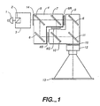
- the display device shown in Figure 1 has a light source 1 comprising a high colour rendering lamp, such as a halogen lamp, a xenon lamp or a metal halide lamp.
- a polarising beam splitter 2 receives light from the light source 1.
- a P-polarised light component passes through the polarising beam splitter 2 and an S-polarised light component is reflected at a reflective surface of the polarising beam splitter 2.
- a polarisation direction converter 3 receives both of the P- and S-polarised light components from the polarising beam splitter 2 and unifies them into either P- or S-polarised light for sending substantially in parallel to light separation means 4.
- a blue colour reflective dichroic mirror 5 receives both of the polarised light components and reflects blue coloured light (less than 500 nm) and transmits other coloured light (yellow colour).
- a light reflector 6 deflects the reflected blue coloured light to a blue colour liquid crystal light valve 8B.
- the other coloured light transmitted through the dichroic mirror 5 is received by a green colour light reflective dichroic mirror 7, which reflects green coloured light (between about 500 nm to about 600 nm), and transmits red coloured light (more than about 600 nm).
- the reflected green coloured light enters a green liquid crystal light valve 8G, while the transmitted red coloured light enters a red liquid crystal light valve 8R.
- the liquid crystal light valves 8R, 8G and 8B modulate optically the respective coloured light to form a picture image for each of the colours according to the amplitude of an applied signal voltage.
- the liquid crystal light valves 8R, 8G and 8B perform a shutter function for controlling the transmittance of incident light.
- the liquid crystal panel may be one which can vary the transmittance in response to signal voltages.
- the liquid crystal light valves 8R, 8G and 8B modulate optically the coloured light for input to light synthesising means 9.
- the blue coloured light is transmitted through a blue colour transmitting dichroic mirror 10 and then is reflected by a red colour transmitting dichroic mirror 11.
- the green coloured light is reflected by the blue colour transmitting dichroic mirror 10 and the red colour transmitting dichroic mirror 11.
- the red coloured light is reflected by a further light reflector 6 and is then transmitted by the red colour transmitting dichroic mirror 11.
- a projecting lens 12 receives colour synthesised light obtained in the above manner to project an enlarged image on a front screen 13.
- the liquid crystal light valves 8R, 8G and 8B can be replaced by arranging the corresponding dichroic mirrors to obtain the light separation and the light synthesis in the same manner as above.
- the liquid crystal light valves 8R, 8G and 8B can display a picture image by selecting the polarised light component using the polarisers 14 and 15.
- the polarising beam splitter 2 which has a degree of polari sation of nearly 100% does not need the polariser 14, which is used simply as an auxiliary polariser for the polarising beam splitter 2.
- Figure 2 is a diagram showing a polarising beam splitter in the form of a cubic polariser comprising a pair of right angled prisms.
- a dielectric layer formed by laminating alternately a high refractive index material and a low refractive index material is coated on the sloping surface of each of the two right angled prisms.
- the polariser is formed by joining the sloping surfaces with an adhesive.
- the non-polarised light is applied at 0° with respect to an outer surface 16 of the cubic polariser (or at 45° with respect to the dielectric laminated coating layer 17 of the adhered interface) and is separated into a P-polarised light component and a S-polarised light component, which are perpendicular with respect to each other, at the dielectric laminated coating layer 17.
- the two components are emitted separately from two outer surfaces 18 and 19, respectively, of the cubic polariser at an accurate angle of 90°. That is, the P-polarised light component of the incident light beam which enters the cubic polariser at a polarisation angle passes through each interface between the laminations of the coating layer 17 totally without reflection.
- the polarised ligh component separation in the cubic polariser shown in Figure 2 uses a similar principle as a polarising beam splitter in the form of a glass plate as described below.
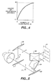
- FIG. 3 is a diagram illustrating the principle of a polarising beam splitter employing a glass plate 20.
- the glass plate 20 has a thickness of about 1 mm.
- ⁇ tan ⁇ 1 (n2 / n1) where n2 is the refractive index of the glass plate 20, n1 is the refractive index of a medium through which the incident light passes before the glass plate 20, and ⁇ is the angle of incidence of the light, 100% of the P-polarised light component 21 passes through and about 15% of the S-polarised light component 22 is reflected by the glass plate ( ⁇ is the polarisation angle in this case).
- ⁇ is the polarisation angle in this case.
- Figure 4 shows the relationship between the number of glass plates 20 indicated along the abscissa and the degree of polarisation indicated along the ordinate as obtained by actual measurements. About an 80% degree of polarisation can be achieved with eight to ten glass plates, with about 30% of the S-polarised light component being absorbed, whereby a temperature rise of the polariser can be minimised.
- Figure 5 shows an embodiment in which light reflectors are used as the polarisation direction converter 3.
- the polarising beam splitter 2 separates light from the light source 1 into a P-polarised light component being transmitted light, and an S-polarised light component being reflected light.
- the travelling direction and the polarising direction of the P-polarised light are converted by light reflectors 23 and 24.
- the travelling direction of the S-polarised light component is changed by light reflectors 25 and 26.
- the two light components travel substantially in the same direction and in parallel and are converted into polarised light in the same polarising direction, to be irradiated in parallel.
- the polarised light which is separated into P- and S-polarised light components can be emitted substantially in parallel by orienting the travelling direction and the polarisation direction by means of a combination of geometric optical reflective direction characteristics. Both of the polarised light components are illuminated separately on a respective half of the aperture of the liquid crystal light valve 8, as shown in Figure 5.
- the cubic polariser or a glass plate polariser may be selected as the polarising beam splitter 2.
- the above mentioned arrangement performs image formation and image projection after the parallel emission.
- the arrangement of the light reflectors can orient the emitted light into a P-polarised light component and can select between vertical parallel emitted light or horizontal parallel emitted light.
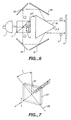
- FIG. 6 is a diagram showing another embodiment using a ⁇ /4 plate as the polarisation direction converter 3 according to the present invention.
- the polarising beam splitter 2 separates emitted light from the light source into a P-polarised light component being transmitted light and an S-polarised light component being reflected light.
- the ⁇ /4 plate 27 transmits the P-polarised light component, converting the straight polarised light into circular polarised light.
- Front reflection means 28 reflect the circular polarised light to reverse its propagation direction. Then, the light is re-converted into straight polarised light by being re-transmitted into the ⁇ /4 plate 27.
- the light is thus converted into an S-polarised light component, which is perpendicular to the polarised light first entering into the ⁇ /4 plate 27, and then goes back to the polarising beam splitter 2.
- the S-polarised light component which is returned to the polarising beam splitter 2 is deflected at the reflective surface of the polarising beam splitter 2 and then passes to a wedge type light reflector 31 after repeated reflection at reflection means 29 and 30.
- the S-polarised light component which is initially reflected at the reflective surface of the polarising beam splitter 2 is symmetrically reflected with respect to the foregoing S-polarised light component transmitted through the ⁇ /4 plate about the light axis of the light source by further reflection means 29 and 30.
- the S-polarised light component then passes to the wedge type light reflector 31 and is deflected by the wedge type light reflector 31 together with the above mentioned converted S-polarised light component to be emitted substantially in parallel, and they are illuminated separately onto the aperture of the liquid crystal light valve 8.
- the wedge type light reflector 31 has a wedge type body formed of a metal, such as aluminium or stainless steel, and a high reflection mirror coating, such as a metal coating and a dielectric laminated coating layer, formed on the surface of the body.
- Figure 7 is a diagram illustrating the principle of the ⁇ /4 plate 27.
- an angle S which is made by the polarised light plane 32 of the incident light and the crystal light axis 33 of the ⁇ /4 plate 27, is 45°, the ⁇ /4 plate 27 converts incident straight polarised light into circular polarised light, or vice versa.
- Figure 8 shows another embodiment according to the present invention using a ⁇ /2 plate as the polarisation direction converter 3.
- the polarising beam splitter 2 separates the light from the light source 1 into a P-polarised light component being transmitted light and an S-polarised light component being reflected light.
- a light reflector 34 deflects the reflected S-polarised light component to a ⁇ /2 plate 35, which rotates the polarised light surface through 90° to produce a P-polarised light component for transmission to a wedge type light reflector 36.
- another light reflector 34 deflects the transmitted P-polarised light component to the wedge type light reflector 36.
- the wedge type light reflector 36 irradiates the two P-polarised light components substantially in parallel and separately to the aperture of the liquid crystal light valve 8.
- the ⁇ /2 plate 35 may also be arranged in the light path of the S-polarised light component entering the light reflector 34. Alternatively, it may be arranged in the light path of the P-polarised light component entering or leaving the other light reflector 34, if an S-polarised light component is to be supplied to the liquid crystal light valve 8.
- the wedge type light reflector 36 is used in a similar manner to that of the embodiment of Figure 6.
- both of the wedge type light reflectors 31 and 36 enable a substantially equal and shortest length of light path to be realised, whereby to prevent an occurrence of a split between the two oriented light components. Therefore, the wedge type light reflector is effectively utilised to realise a bright projected picture image with reduced unevenness.
- Figure 9 is a diagram showing the principle of the ⁇ /2 plate 35.
- the angle S which is made by the polarised light plane 37 of the incident light and the crystal light axis 38 of the ⁇ /2 plate is 45°
- the ⁇ /2 plate 35 rotates the polarisation plane of the incident polarised light through 90° so that the P- (or S-) polarised light component is converted into an S-(or P-) polarised light component.
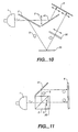
- FIG 10 is a diagram showing another embodiment using the ⁇ /2 plate 35 as the polarisation direction converter 3.
- the polarising beam splitter 2 separates the light from the light source 1 into a P-polarised light component being transmitted light and an S-polarised light component being reflected light.
- a light reflector 39 deflects the S-polarised light component to the ⁇ /2 plate 35.
- the ⁇ /2 plate 35 rotates the polarised light plane through 90° to convert it into a P-polarised light component which travels straight ahead to the liquid crystal light valve 8.
- a light reflector 40 also reflects the P-polarised light component from the polarising beam splitter 2 to the aperture of the liquid crystal light valve 8.
- the P- polarised light components are irradiated together in parallel and without any space between them in the same direction.
- the ⁇ /2 plate 35 may be arranged either in front of the light reflector 39, or in front or to the rear of the light reflector 40.
- the present embodiment is an improvement over that of Figure 8, in that a simple structure using two light reflectors can realise the desired purpose.
- Figure 11 is a diagram showing another embodiment using the ⁇ /2 plate 35 as the polarisation direction converter 3.
- the polarising beam splitter 2 separates the light from the light source 1 into a P-polarised light component being transmitted light and an S-polarised light component being reflected light.
- the ⁇ /2 plate 35 is arranged close to the polarising beam splitter 2.
- the transmitted P-polarised light component is rotated through 90° after passing through the ⁇ /2 plate 35 so that it is converted into an S-polarised light component travelling straight ahead.
- the S-polarised light component reflected by the polarising beam splitter 2 is reflected by a light reflector 41 in the same direction as that of the other S-polarised light component whereby the two S-polarised light components are separately projected substantially in parallel and without any space between them onto the aperture of the liquid crystal light valve 8.
- the present embodiment represents the simplest construction as compared with those of Figures 8 and 10.
- Figure 12 shows an embodiment in which a combination of a convex lens 42 and a concave lens 43 is arranged immediately after the polarisation direction converter 3 shown in Figure 11.
- This configuration can be applied similarly in the other embodiments.
- the vertical cross sectional area of the light emitted in parallel from the polarisation direction converter 3 is approximately twice that of the light from the light source 1. Therefore, in order to utilise the light from the light source 1 effectively, the aperture area of the liquid crystal light valve 8 is required to be enlarged to be nearly twice as large as the vertical cross sectional area of the light emitted from the light source 1.
- the present embodiment may provide a bright and compact liquid crystal display device by employing a smaller liquid crystal light valve in combination with a larger light source.
- the parallel light emitted by the polarisation direction converter 3 is condensed by the convex lens 42 and re-converted to a parallel beam by the concave lens 43, so that the light from the concave lens 43 is changed into a parallel light with a small cross sectional area by comparison with that of the light entering the convex lens 42 and can be irradiated separately onto the liquid crystal light valve 8.
- the aspect ratio of the liquid crystal light valve 8 is 4:3 or 16:9 in the above mentioned embodiments the longer the sideways aperture the liquid crystal light valve 8 has, the more the half-separating irradiation shows notable effect.
- the half-separation irradiation of the present invention provides an improved illumination ratio for the picture image as well as a brighter picture image.
- the light source 1 and the polariser 14 are arranged at a proper distance so that the polariser 14 is outside the influence of heat from the light source 1 on the absorption of the polarised light component.
- a low revolution type cooling fan can provide stable reliability for the device under a wide range of ambient temperatures. Therefore, a high revolution type cooling fan with high cooling capability is not required. With respect to the temperature condition, it is preferable to remove the polariser 14.
- a projection type liquid crystal display device is constructed such that light emitted from a light source is separated into a P-polarised light component and an S-polarised light component by a polarising beam splitter, both of the polarised light components are directed in the same polarising direction and substantially in parallel, and a picture image is projected by separately projecting the components onto the aperture of a liquid crystal light valve, whereby most of the light sent from the light source can be incident onto the aperture of the liquid crystal light valve and a high intensity picture image can be realised by utilising the maximum light flux from the light source.
Priority Applications (1)
| Application Number | Priority Date | Filing Date | Title |
|---|---|---|---|
| EP97200412A EP0777146B1 (fr) | 1989-10-05 | 1990-09-17 | Dispositif d'affichage par projection |
Applications Claiming Priority (2)
| Application Number | Priority Date | Filing Date | Title |
|---|---|---|---|
| JP260882/89 | 1989-10-05 | ||
| JP1260882A JP2893599B2 (ja) | 1989-10-05 | 1989-10-05 | 偏光光源及び投写型表示装置 |
Related Child Applications (2)
| Application Number | Title | Priority Date | Filing Date |
|---|---|---|---|
| EP97200412A Division EP0777146B1 (fr) | 1989-10-05 | 1990-09-17 | Dispositif d'affichage par projection |
| EP97200412.1 Division-Into | 1997-02-13 |
Publications (3)
| Publication Number | Publication Date |
|---|---|
| EP0421628A2 true EP0421628A2 (fr) | 1991-04-10 |
| EP0421628A3 EP0421628A3 (en) | 1992-04-15 |
| EP0421628B1 EP0421628B1 (fr) | 1997-12-03 |
Family
ID=17354061
Family Applications (2)
| Application Number | Title | Priority Date | Filing Date |
|---|---|---|---|
| EP90310142A Expired - Lifetime EP0421628B1 (fr) | 1989-10-05 | 1990-09-17 | Dispositif d'affichage LCD pour projection |
| EP97200412A Expired - Lifetime EP0777146B1 (fr) | 1989-10-05 | 1990-09-17 | Dispositif d'affichage par projection |
Family Applications After (1)
| Application Number | Title | Priority Date | Filing Date |
|---|---|---|---|
| EP97200412A Expired - Lifetime EP0777146B1 (fr) | 1989-10-05 | 1990-09-17 | Dispositif d'affichage par projection |
Country Status (4)
| Country | Link |
|---|---|
| US (2) | US5200843A (fr) |
| EP (2) | EP0421628B1 (fr) |
| JP (1) | JP2893599B2 (fr) |
| DE (2) | DE69033658T2 (fr) |
Cited By (8)
| Publication number | Priority date | Publication date | Assignee | Title |
|---|---|---|---|---|
| WO1994007233A1 (fr) * | 1992-09-11 | 1994-03-31 | Tunnelvision Ab | Procede d'affichage d'images et appareil prevu a cet effet |
| EP0600728A1 (fr) * | 1992-12-03 | 1994-06-08 | Matsushita Electric Industrial Co., Ltd. | Rotateur de polarisation plan applicable à un convertisseur de polarisation et système d'affichage par projection |
| EP0601628A1 (fr) * | 1992-12-02 | 1994-06-15 | Koninklijke Philips Electronics N.V. | Dispositif optique de projection |
| DE4435450A1 (de) * | 1993-10-04 | 1995-04-06 | Matsushita Electric Ind Co Ltd | Flüssigkristalleinheit und Projektionsanzeige unter Verwendung einer Flüssigkristalleinheit |
| US6147725A (en) * | 1997-11-21 | 2000-11-14 | Mitsubishi Denki Kabushiki Kaisha | Liquid crystal panel module with polarization transformation for increased brightness |
| WO2001013079A1 (fr) * | 1999-08-18 | 2001-02-22 | Swinburne University | Procede et appareil de separation de faisceaux de rayonnement electromagnetique |
| WO2001027693A2 (fr) * | 2000-10-10 | 2001-04-19 | Digilens, Inc. | Systeme de projection mettant en application des elements optiques holographiques commutables |
| US6424437B1 (en) | 2000-10-10 | 2002-07-23 | Digilens, Inc. | Projection display employing switchable holographic optical elements |
Families Citing this family (105)
| Publication number | Priority date | Publication date | Assignee | Title |
|---|---|---|---|---|
| DE69028497T2 (de) * | 1989-12-20 | 1997-02-06 | Canon Kk | Polarisierendes Beleuchtungsgerät |
| JP2752751B2 (ja) * | 1989-12-20 | 1998-05-18 | キヤノン株式会社 | 表示装置 |
| US5570209A (en) * | 1990-09-18 | 1996-10-29 | Mitsubishi Denki Kabushiki Kaisha | Color projection type display apparatus having three liquid crystal displays of same structure |
| JP2575558Y2 (ja) * | 1990-12-26 | 1998-07-02 | エルジー電子株式会社 | 液晶投写形ディスプレイの光学系構造 |
| US6392689B1 (en) * | 1991-02-21 | 2002-05-21 | Eugene Dolgoff | System for displaying moving images pseudostereoscopically |
| JP3039570B2 (ja) * | 1991-06-24 | 2000-05-08 | キヤノン株式会社 | 投写表示装置 |
| US5311217A (en) * | 1991-12-23 | 1994-05-10 | Xerox Corporation | Variable attenuator for dual beams |
| US5303085A (en) | 1992-02-07 | 1994-04-12 | Rallison Richard D | Optically corrected helmet mounted display |
| US5864326A (en) | 1992-02-07 | 1999-01-26 | I-O Display Systems Llc | Depixelated visual display |
| US6097543A (en) | 1992-02-07 | 2000-08-01 | I-O Display Systems Llc | Personal visual display |
| JPH05241103A (ja) * | 1992-02-21 | 1993-09-21 | Nec Corp | 投射型液晶表示装置 |
| US5903388A (en) * | 1992-06-11 | 1999-05-11 | Sedlmayr Steven R | High efficiency electromagnetic beam projector and systems and method for implementation thereof |
| TW594115B (en) * | 1992-10-09 | 2004-06-21 | Asahi Glass Co Ltd | A liquid crystal display device and an illumination device for a direct viewing type display element |
| USRE37377E1 (en) | 1992-10-09 | 2001-09-18 | Asahi Glass Company, Ltd. | LCD device including an illumination device having a polarized light separating sheet between a light guide and the display |
| US5526022A (en) | 1993-01-06 | 1996-06-11 | Virtual I/O, Inc. | Sourceless orientation sensor |
| US5594561A (en) * | 1993-03-31 | 1997-01-14 | Palomar Technologies Corporation | Flat panel display with elliptical diffuser and fiber optic plate |
| JP3168765B2 (ja) * | 1993-04-01 | 2001-05-21 | 松下電器産業株式会社 | 偏光装置および該偏光装置を用いた投写型表示装置 |
| US5621551A (en) * | 1993-04-30 | 1997-04-15 | Hughes-Jvc Technology Corporation | Immersed dichroic system for single projection lens liquid crystal video projector |
| US5512967A (en) * | 1993-09-28 | 1996-04-30 | Proxima Corporation | Projector |
| US5748828A (en) * | 1993-11-10 | 1998-05-05 | Alliedsignal Inc. | Color separating backlight |
| US5991087A (en) | 1993-11-12 | 1999-11-23 | I-O Display System Llc | Non-orthogonal plate in a virtual reality or heads up display |
| EP0735952B1 (fr) * | 1993-12-21 | 2000-03-22 | Minnesota Mining And Manufacturing Company | Film optique multicouche |
| US5882774A (en) * | 1993-12-21 | 1999-03-16 | Minnesota Mining And Manufacturing Company | Optical film |
| US20070091230A1 (en) * | 1993-12-21 | 2007-04-26 | 3M Innovative Properties Company | Display incorporating reflective polarizer |
| US6804058B1 (en) | 1993-12-21 | 2004-10-12 | 3M Innovative Properties Company | Electroluminescent light source and display incorporating same |
| US6096375A (en) * | 1993-12-21 | 2000-08-01 | 3M Innovative Properties Company | Optical polarizer |
| US5828488A (en) * | 1993-12-21 | 1998-10-27 | Minnesota Mining And Manufacturing Co. | Reflective polarizer display |
| US6025897A (en) * | 1993-12-21 | 2000-02-15 | 3M Innovative Properties Co. | Display with reflective polarizer and randomizing cavity |
| AU2156295A (en) * | 1994-02-07 | 1995-08-21 | Virtual I/O, Inc. | Personal visual display |
| US6160666A (en) | 1994-02-07 | 2000-12-12 | I-O Display Systems Llc | Personal visual display system |
| US6101032A (en) | 1994-04-06 | 2000-08-08 | 3M Innovative Properties Company | Light fixture having a multilayer polymeric film |
| US5600487A (en) * | 1994-04-14 | 1997-02-04 | Omron Corporation | Dichroic mirror for separating/synthesizing light with a plurality of wavelengths and optical apparatus and detecting method using the same |
| JPH07294850A (ja) * | 1994-04-22 | 1995-11-10 | Canon Inc | 照明装置及びそれを用いた投影装置 |
| DE69535145T2 (de) * | 1994-06-01 | 2007-06-14 | Koninklijke Philips Electronics N.V. | Beleuchtungsgerät mit hohem wirkungsgrad und dieses gerät enthaltende projektionseinrichtung |
| US5903395A (en) | 1994-08-31 | 1999-05-11 | I-O Display Systems Llc | Personal visual display system |
| JP3219943B2 (ja) * | 1994-09-16 | 2001-10-15 | 株式会社東芝 | 平面直視型表示装置 |
| US5808800A (en) * | 1994-12-22 | 1998-09-15 | Displaytech, Inc. | Optics arrangements including light source arrangements for an active matrix liquid crystal image generator |
| EP0752608A4 (fr) * | 1994-12-27 | 1998-01-14 | Seiko Epson Corp | Visuel du type a projection |
| WO1996020422A1 (fr) | 1994-12-28 | 1996-07-04 | Seiko Epson Corporation | Appareil d'eclairage en lumiere polarisee et dispositif d'affichage du type a projection |
| US5991085A (en) | 1995-04-21 | 1999-11-23 | I-O Display Systems Llc | Head-mounted personal visual display apparatus with image generator and holder |
| US5757547A (en) * | 1995-04-24 | 1998-05-26 | Polycom, Inc. | High efficiency homogeneous polarization converter |
| JPH08339710A (ja) * | 1995-06-12 | 1996-12-24 | Nikon Corp | 光源装置 |
| US5686979A (en) * | 1995-06-26 | 1997-11-11 | Minnesota Mining And Manufacturing Company | Optical panel capable of switching between reflective and transmissive states |
| US5608552A (en) * | 1995-12-26 | 1997-03-04 | Hughes Electronics | Liquid crystal display having an off-axis full-color holographic filter |
| TW401530B (en) * | 1996-03-12 | 2000-08-11 | Seiko Epson Corp | Polarized light separation device, method of fabricating the same and projection display apparatus using the polarized light separation device |
| US6049403A (en) * | 1996-07-25 | 2000-04-11 | Delta America Ltd. | V-splitter for optical engine |
| JP3791130B2 (ja) * | 1996-08-19 | 2006-06-28 | セイコーエプソン株式会社 | 投写型表示装置 |
| CN101256339B (zh) * | 1996-08-19 | 2010-06-23 | 精工爱普生株式会社 | 投影式显示装置 |
| JP3473335B2 (ja) | 1996-08-19 | 2003-12-02 | セイコーエプソン株式会社 | 投写型表示装置 |
| JP2894290B2 (ja) * | 1996-08-20 | 1999-05-24 | 日本電気株式会社 | 投射型カラー液晶表示装置 |
| US6356322B1 (en) * | 1996-09-30 | 2002-03-12 | Fuji Photo Film Co., Ltd. | Liquid crystal display system with improved contrast and less dependence on visual angle |
| US5975703A (en) * | 1996-09-30 | 1999-11-02 | Digital Optics International | Image projection system |
| JPH10186282A (ja) * | 1996-11-11 | 1998-07-14 | Sharp Corp | 投影型画像表示装置 |
| US6249378B1 (en) * | 1997-02-28 | 2001-06-19 | Nikon Corporation | Mirror and projection type display apparatus |
| US5973833A (en) * | 1997-08-29 | 1999-10-26 | Lightware, Inc. | High efficiency polarizing converter |
| US5903396A (en) | 1997-10-17 | 1999-05-11 | I/O Display Systems, Llc | Intensified visual display |
| US7023602B2 (en) | 1999-05-17 | 2006-04-04 | 3M Innovative Properties Company | Reflective LCD projection system using wide-angle Cartesian polarizing beam splitter and color separation and recombination prisms |
| US6486997B1 (en) | 1997-10-28 | 2002-11-26 | 3M Innovative Properties Company | Reflective LCD projection system using wide-angle Cartesian polarizing beam splitter |
| JP3614001B2 (ja) * | 1997-12-03 | 2005-01-26 | セイコーエプソン株式会社 | 投影装置 |
| US5940149A (en) * | 1997-12-11 | 1999-08-17 | Minnesota Mining And Manufacturing Company | Planar polarizer for LCD projectors |
| US6808658B2 (en) * | 1998-01-13 | 2004-10-26 | 3M Innovative Properties Company | Method for making texture multilayer optical films |
| JP2002508092A (ja) * | 1998-04-02 | 2002-03-12 | コーニンクレッカ フィリップス エレクトロニクス エヌ ヴィ | 増強された輝度を有する画像投射装置 |
| US6108131A (en) | 1998-05-14 | 2000-08-22 | Moxtek | Polarizer apparatus for producing a generally polarized beam of light |
| US6104536A (en) * | 1998-09-18 | 2000-08-15 | 3M Innovative Properties Company | High efficiency polarization converter including input and output lenslet arrays |
| JP2000206613A (ja) * | 1999-01-11 | 2000-07-28 | Sony Corp | 投射型表示装置 |
| US6995917B1 (en) | 1999-04-08 | 2006-02-07 | Sharp Laboratories Of America, Inc. | Projection display system using polarized light |
| US6737124B2 (en) | 2000-12-15 | 2004-05-18 | Displaytech, Inc. | Liquid crystal compounds having a silane tail with a perfluoroalkyl terminal portion |
| US6783812B2 (en) | 2000-12-15 | 2004-08-31 | Displaytech, Inc. | Alkyl silane liquid crystal compounds |
| US7195719B1 (en) | 2001-01-03 | 2007-03-27 | Displaytech, Inc. | High polarization ferroelectric liquid crystal compositions |
| US6838128B1 (en) | 2002-02-05 | 2005-01-04 | Displaytech, Inc. | High polarization dopants for ferroelectric liquid crystal compositions |
| TWI289708B (en) * | 2002-12-25 | 2007-11-11 | Qualcomm Mems Technologies Inc | Optical interference type color display |
| TW594053B (en) * | 2003-03-25 | 2004-06-21 | Delta Electronics Inc | Image projection apparatus and its optical polarization module |
| US8164721B2 (en) | 2003-12-11 | 2012-04-24 | Tan Kim L | Grating trim retarders |
| US7626661B2 (en) * | 2003-12-11 | 2009-12-01 | Jds Uniphase Corporation | Polarization controlling elements |
| US7342705B2 (en) | 2004-02-03 | 2008-03-11 | Idc, Llc | Spatial light modulator with integrated optical compensation structure |
| US20060132383A1 (en) * | 2004-09-27 | 2006-06-22 | Idc, Llc | System and method for illuminating interferometric modulator display |
| US20060066586A1 (en) * | 2004-09-27 | 2006-03-30 | Gally Brian J | Touchscreens for displays |
| US7630123B2 (en) | 2004-09-27 | 2009-12-08 | Qualcomm Mems Technologies, Inc. | Method and device for compensating for color shift as a function of angle of view |
| JP4903407B2 (ja) * | 2005-08-29 | 2012-03-28 | Necディスプレイソリューションズ株式会社 | 投射型表示装置の光の調整方法 |
| US7896489B2 (en) * | 2005-11-02 | 2011-03-01 | Fujifilm Corporation | Image recording apparatus |
| WO2008042798A2 (fr) | 2006-09-29 | 2008-04-10 | Colorlink, Inc. | Systèmes de conversion de polarisation pour une projection stéréoscopique |
| EP1943551A2 (fr) | 2006-10-06 | 2008-07-16 | Qualcomm Mems Technologies, Inc. | Guide de lumière |
| EP1943555B1 (fr) * | 2006-10-06 | 2012-05-02 | QUALCOMM MEMS Technologies, Inc. | Structure d'affaiblissement optique intégrée dans un appareil d'éclairage |
| WO2008045462A2 (fr) * | 2006-10-10 | 2008-04-17 | Qualcomm Mems Technologies, Inc. | Dispositif d'affichage à optiques diffractives |
| US7857455B2 (en) * | 2006-10-18 | 2010-12-28 | Reald Inc. | Combining P and S rays for bright stereoscopic projection |
| CN103383494B (zh) | 2007-05-09 | 2021-10-29 | 瑞尔D股份有限公司 | 用于立体投影的偏振转换系统和方法 |
| US8068710B2 (en) | 2007-12-07 | 2011-11-29 | Qualcomm Mems Technologies, Inc. | Decoupled holographic film and diffuser |
| US7949213B2 (en) * | 2007-12-07 | 2011-05-24 | Qualcomm Mems Technologies, Inc. | Light illumination of displays with front light guide and coupling elements |
| US20090168459A1 (en) * | 2007-12-27 | 2009-07-02 | Qualcomm Incorporated | Light guide including conjugate film |
| US8721149B2 (en) | 2008-01-30 | 2014-05-13 | Qualcomm Mems Technologies, Inc. | Illumination device having a tapered light guide |
| JP2011512006A (ja) | 2008-01-30 | 2011-04-14 | デジタル オプティクス インターナショナル,リミティド ライアビリティ カンパニー | 薄型照明システム |
| US8422132B2 (en) | 2008-12-02 | 2013-04-16 | Shanghai Lexvu Opto Microelectronics Technology Co., Ltd. | Integrated planar polarizing device |
| WO2010138765A1 (fr) * | 2009-05-29 | 2010-12-02 | Qualcomm Mems Technologies, Inc. | Dispositifs d'éclairage et procédés de fabrication associés |
| WO2011014207A1 (fr) | 2009-07-31 | 2011-02-03 | University Of Utah Research Foundation | Module de séparateur de faisceau |
| US8902484B2 (en) | 2010-12-15 | 2014-12-02 | Qualcomm Mems Technologies, Inc. | Holographic brightness enhancement film |
| JP5910031B2 (ja) * | 2011-11-28 | 2016-04-27 | ソニー株式会社 | 投影装置 |
| JP5906692B2 (ja) * | 2011-11-29 | 2016-04-20 | セイコーエプソン株式会社 | 表示装置 |
| US9625745B2 (en) | 2013-11-15 | 2017-04-18 | Reald Inc. | High dynamic range, high contrast projection systems |
| US9851575B2 (en) * | 2014-05-15 | 2017-12-26 | Omnivision Technologies, Inc. | Wafer-level liquid-crystal-on-silicon projection assembly, systems and methods |
| KR20160147636A (ko) * | 2015-06-15 | 2016-12-23 | 삼성전자주식회사 | 헤드 마운티드 디스플레이 장치 |
| WO2016204433A1 (fr) * | 2015-06-15 | 2016-12-22 | Samsung Electronics Co., Ltd. | Visiocasque |
| CN109219775B (zh) * | 2016-06-03 | 2022-01-25 | 金泰克斯公司 | 具有相位定向反射控制的显示系统 |
| CN109584741A (zh) * | 2018-12-04 | 2019-04-05 | 深圳绿米联创科技有限公司 | 一种隐藏式屏下光学模组及电子设备 |
| CN110519419A (zh) * | 2019-07-17 | 2019-11-29 | 华为技术有限公司 | 电子设备 |
| CN115542639A (zh) * | 2021-06-11 | 2022-12-30 | 中兴通讯股份有限公司 | 屏下摄像显示装置及其控制方法、控制器和终端设备 |
Citations (2)
| Publication number | Priority date | Publication date | Assignee | Title |
|---|---|---|---|---|
| EP0083440A2 (fr) * | 1981-12-28 | 1983-07-13 | Hughes Aircraft Company | Système pour la projection bicolore d'images par des valves de lumière à cristal liquide avec prépolarisation |
| EP0210088A1 (fr) * | 1985-07-12 | 1987-01-28 | Sextant Avionique S.A. | Appareil de visualisation à champ étendu dans lequel l'image est formée par la juxtaposition d'au moins deux images partielles |
Family Cites Families (36)
| Publication number | Priority date | Publication date | Assignee | Title |
|---|---|---|---|---|
| US4127322A (en) * | 1975-12-05 | 1978-11-28 | Hughes Aircraft Company | High brightness full color image light valve projection system |
| US4425028A (en) * | 1981-12-28 | 1984-01-10 | Hughes Aircraft Company | High efficiency optical tank for three color liquid crystal light valve image projection with color selective prepolarization and single projection lens |
| US4500172A (en) * | 1981-12-28 | 1985-02-19 | Hughes Aircraft Company | Two color liquid crystal light valve image projection system with single prepolarizer |
| JPS59201026A (ja) * | 1983-04-30 | 1984-11-14 | Fujitsu Ltd | 偏光素子 |
| US4516837A (en) * | 1983-02-22 | 1985-05-14 | Sperry Corporation | Electro-optical switch for unpolarized optical signals |
| JPS61145503A (ja) * | 1984-12-20 | 1986-07-03 | Fujitsu Ltd | 光分離合成用プリズム |
| JPS6211823A (ja) * | 1985-07-10 | 1987-01-20 | Mitsubishi Electric Corp | 偏光変換器 |
| JPS6215518A (ja) * | 1985-07-15 | 1987-01-23 | Mitsubishi Electric Corp | 偏光変換器 |
| US4690526A (en) * | 1985-09-12 | 1987-09-01 | Hughes Aircraft Company | Prism assembly for a single light valve full-color projector |
| JPS6315219A (ja) * | 1986-07-08 | 1988-01-22 | Seikosha Co Ltd | 投写式液晶表示装置 |
| JPH0792561B2 (ja) * | 1986-07-08 | 1995-10-09 | 株式会社精工舎 | 投写式液晶表示装置 |
| US4864390A (en) * | 1986-08-22 | 1989-09-05 | North American Philips Corporation | Display system with equal path lengths |
| JPS63123018A (ja) * | 1986-11-12 | 1988-05-26 | Hitachi Ltd | 投射型液晶表示装置 |
| JPH0769539B2 (ja) | 1986-11-12 | 1995-07-31 | 株式会社日立製作所 | 液晶表示装置 |
| JPS63168622A (ja) * | 1987-01-05 | 1988-07-12 | Canon Inc | 光偏向素子 |
| JPS63185188A (ja) | 1987-01-27 | 1988-07-30 | Canon Inc | Lcdプロジエクタ装置 |
| US4989076A (en) * | 1987-01-27 | 1991-01-29 | Canon Kabushiki Kaisha | Video projection apparatus |
| US4786146A (en) * | 1987-02-11 | 1988-11-22 | Hughes Aircraft Company | Color sequential illumination system for a liquid crystal light valve |
| JP2691530B2 (ja) * | 1987-03-04 | 1997-12-17 | セイコーエプソン株式会社 | 投写型カラー表示装置 |
| EP0287034B1 (fr) * | 1987-04-14 | 1995-01-18 | Seiko Epson Corporation | Dispositif d'affichage à cristal liquide en couleurs par projection |
| JPS63271313A (ja) * | 1987-04-30 | 1988-11-09 | Nikon Corp | 偏光器 |
| US4749259A (en) * | 1987-05-15 | 1988-06-07 | Hughes Aircraft Company | Liquid crystal image projection with multicolor prepolarizing system |
| DE3720375A1 (de) * | 1987-06-19 | 1988-12-29 | Fraunhofer Ges Forschung | Projektionsvorrichtung |
| JPH0830789B2 (ja) * | 1987-08-19 | 1996-03-27 | 富士通株式会社 | 偏光分離合成プリズム |
| JPH0218825A (ja) * | 1988-07-07 | 1990-01-23 | Toshiba Corp | ガス遮断器 |
| GB8816983D0 (en) * | 1988-07-16 | 1988-08-17 | Jaguar Cars | Pistons |
| GB8816981D0 (en) * | 1988-07-16 | 1988-08-17 | Jaguar Cars | Pistons |
| JP2629871B2 (ja) * | 1988-08-29 | 1997-07-16 | スズキ株式会社 | 車両用変速機 |
| JPH0262475A (ja) * | 1988-08-29 | 1990-03-02 | Tokyo Sokuhan Co Ltd | 自動変速機付車両の速度制御装置 |
| JP2730734B2 (ja) * | 1988-08-30 | 1998-03-25 | マツダ株式会社 | 自動変速機搭載車のエンジン出力制御装置 |
| JPH0264613A (ja) * | 1988-08-31 | 1990-03-05 | Seiko Epson Corp | 偏光光源 |
| JP2874163B2 (ja) * | 1988-09-06 | 1999-03-24 | セイコーエプソン株式会社 | 偏光光源、液晶表示装置及び投射型表示装置 |
| US5042921A (en) * | 1988-10-25 | 1991-08-27 | Casio Computer Co., Ltd. | Liquid crystal display apparatus |
| JPH02153336A (ja) * | 1988-12-05 | 1990-06-13 | Sharp Corp | 投影型液晶表示装置 |
| US4913529A (en) * | 1988-12-27 | 1990-04-03 | North American Philips Corp. | Illumination system for an LCD display system |
| JP2800271B2 (ja) * | 1989-06-07 | 1998-09-21 | カシオ計算機株式会社 | 液晶表示装置 |
-
1989
- 1989-10-05 JP JP1260882A patent/JP2893599B2/ja not_active Expired - Lifetime
-
1990
- 1990-09-17 DE DE69033658T patent/DE69033658T2/de not_active Expired - Lifetime
- 1990-09-17 EP EP90310142A patent/EP0421628B1/fr not_active Expired - Lifetime
- 1990-09-17 EP EP97200412A patent/EP0777146B1/fr not_active Expired - Lifetime
- 1990-09-17 DE DE69031773T patent/DE69031773T2/de not_active Expired - Lifetime
- 1990-10-05 US US07/593,107 patent/US5200843A/en not_active Expired - Lifetime
-
1992
- 1992-10-30 US US07/968,696 patent/US5278680A/en not_active Expired - Lifetime
Patent Citations (2)
| Publication number | Priority date | Publication date | Assignee | Title |
|---|---|---|---|---|
| EP0083440A2 (fr) * | 1981-12-28 | 1983-07-13 | Hughes Aircraft Company | Système pour la projection bicolore d'images par des valves de lumière à cristal liquide avec prépolarisation |
| EP0210088A1 (fr) * | 1985-07-12 | 1987-01-28 | Sextant Avionique S.A. | Appareil de visualisation à champ étendu dans lequel l'image est formée par la juxtaposition d'au moins deux images partielles |
Non-Patent Citations (5)
| Title |
|---|
| PATENT ABSTRACTS OF JAPAN vol. 12, no. 370 (P-767)(3217) 5 October 1988 & JP-A-63 121 821 ( HITACHI ) 25 May 1988 * |
| PATENT ABSTRACTS OF JAPAN vol. 12, no. 377 (P-768)(3224) 7 October 1988 & JP-A-63 123 018 ( HITACHI ) 26 May 1988 * |
| PATENT ABSTRACTS OF JAPAN vol. 12, no. 439 (P-788)(3286) 18 November 1988 & JP-A-63 168 622 ( CANON ) 12 July 1988 * |
| PATENT ABSTRACTS OF JAPAN vol. 12, no. 461 (E-689)5 December 1988 & JP-A-63 185 188 ( CANON ) 30 July 1988 * |
| PATENT ABSTRACTS OF JAPAN vol. 13, no. 89 (P-836)(3437) 2 March 1989 & JP-A-63 271 313 ( NIKON ) 9 November 1988 * |
Cited By (12)
| Publication number | Priority date | Publication date | Assignee | Title |
|---|---|---|---|---|
| WO1994007233A1 (fr) * | 1992-09-11 | 1994-03-31 | Tunnelvision Ab | Procede d'affichage d'images et appareil prevu a cet effet |
| EP0601628A1 (fr) * | 1992-12-02 | 1994-06-15 | Koninklijke Philips Electronics N.V. | Dispositif optique de projection |
| US5459539A (en) * | 1992-12-02 | 1995-10-17 | U.S. Philips Corporation | Optical projection apparatus |
| KR100369087B1 (ko) * | 1992-12-02 | 2003-12-11 | 코닌클리케 필립스 일렉트로닉스 엔.브이. | 광투사장치 |
| EP0600728A1 (fr) * | 1992-12-03 | 1994-06-08 | Matsushita Electric Industrial Co., Ltd. | Rotateur de polarisation plan applicable à un convertisseur de polarisation et système d'affichage par projection |
| US5657160A (en) * | 1992-12-03 | 1997-08-12 | Matsushita Electric Industrial Co., Ltd. | Polarization plane rotator applicable to polarization converter and projection display system |
| DE4435450A1 (de) * | 1993-10-04 | 1995-04-06 | Matsushita Electric Ind Co Ltd | Flüssigkristalleinheit und Projektionsanzeige unter Verwendung einer Flüssigkristalleinheit |
| US6147725A (en) * | 1997-11-21 | 2000-11-14 | Mitsubishi Denki Kabushiki Kaisha | Liquid crystal panel module with polarization transformation for increased brightness |
| WO2001013079A1 (fr) * | 1999-08-18 | 2001-02-22 | Swinburne University | Procede et appareil de separation de faisceaux de rayonnement electromagnetique |
| WO2001027693A2 (fr) * | 2000-10-10 | 2001-04-19 | Digilens, Inc. | Systeme de projection mettant en application des elements optiques holographiques commutables |
| WO2001027693A3 (fr) * | 2000-10-10 | 2001-12-20 | Digilens Inc | Systeme de projection mettant en application des elements optiques holographiques commutables |
| US6424437B1 (en) | 2000-10-10 | 2002-07-23 | Digilens, Inc. | Projection display employing switchable holographic optical elements |
Also Published As
| Publication number | Publication date |
|---|---|
| EP0777146A1 (fr) | 1997-06-04 |
| DE69033658T2 (de) | 2001-03-01 |
| JP2893599B2 (ja) | 1999-05-24 |
| US5200843A (en) | 1993-04-06 |
| EP0421628B1 (fr) | 1997-12-03 |
| US5278680A (en) | 1994-01-11 |
| JPH03122631A (ja) | 1991-05-24 |
| DE69031773T2 (de) | 1998-03-26 |
| DE69031773D1 (de) | 1998-01-15 |
| EP0421628A3 (en) | 1992-04-15 |
| DE69033658D1 (de) | 2000-12-07 |
| EP0777146B1 (fr) | 2000-11-02 |
Similar Documents
| Publication | Publication Date | Title |
|---|---|---|
| EP0421628B1 (fr) | Dispositif d'affichage LCD pour projection | |
| US7452086B2 (en) | Light pipe based projection engine | |
| JP3423807B2 (ja) | プリズム装置および液晶プロジェクション装置 | |
| JP2738324B2 (ja) | 投写型液晶表示装置 | |
| US6987618B2 (en) | Polarization converting device, illumination optical system and projector | |
| JPS6259919A (ja) | 投写型カラ−表示装置 | |
| JPH068985B2 (ja) | 投写型表示装置 | |
| JPH11202432A (ja) | 投射型画像表示装置 | |
| JP3335885B2 (ja) | 偏光照明装置、および投写型液晶表示装置 | |
| JP4247042B2 (ja) | 投写型表示装置 | |
| JPH11160791A (ja) | 照明光学装置およびこの照明光学装置を使用した投写型表示装置 | |
| JPH11119151A (ja) | 光源装置および投影装置 | |
| JPH1039258A (ja) | 単一偏光変換素子及び投射型表示装置 | |
| JP3797756B2 (ja) | 液晶プロジェクター | |
| JPH0772428A (ja) | 投写型液晶表示装置の偏光光源装置 | |
| JP4077490B2 (ja) | 投射型映像表示装置 | |
| KR100359728B1 (ko) | 액정 프로젝터의 광학 장치 | |
| JPS63216025A (ja) | 投写型カラ−表示装置 | |
| JP2003337375A (ja) | プロジェクタ | |
| JP2001117050A (ja) | 照明装置と投射型表示装置 | |
| JPH10319350A (ja) | 偏光照明装置及び投射型表示装置 | |
| JPH06265895A (ja) | 光源装置 | |
| JPH07294867A (ja) | 投写型表示装置 | |
| JPH10221690A (ja) | 偏光光照明装置及び投写型画像表示装置 | |
| JPH04233580A (ja) | 液晶プロジェクター |
Legal Events
| Date | Code | Title | Description |
|---|---|---|---|
| PUAI | Public reference made under article 153(3) epc to a published international application that has entered the european phase |
Free format text: ORIGINAL CODE: 0009012 |
|
| AK | Designated contracting states |
Kind code of ref document: A2 Designated state(s): DE FR GB NL |
|
| PUAL | Search report despatched |
Free format text: ORIGINAL CODE: 0009013 |
|
| AK | Designated contracting states |
Kind code of ref document: A3 Designated state(s): DE FR GB NL |
|
| 17P | Request for examination filed |
Effective date: 19920909 |
|
| 17Q | First examination report despatched |
Effective date: 19941012 |
|
| GRAG | Despatch of communication of intention to grant |
Free format text: ORIGINAL CODE: EPIDOS AGRA |
|
| GRAG | Despatch of communication of intention to grant |
Free format text: ORIGINAL CODE: EPIDOS AGRA |
|
| GRAH | Despatch of communication of intention to grant a patent |
Free format text: ORIGINAL CODE: EPIDOS IGRA |
|
| GRAH | Despatch of communication of intention to grant a patent |
Free format text: ORIGINAL CODE: EPIDOS IGRA |
|
| GRAA | (expected) grant |
Free format text: ORIGINAL CODE: 0009210 |
|
| AK | Designated contracting states |
Kind code of ref document: B1 Designated state(s): DE FR GB NL |
|
| PG25 | Lapsed in a contracting state [announced via postgrant information from national office to epo] |
Ref country code: NL Free format text: LAPSE BECAUSE OF FAILURE TO SUBMIT A TRANSLATION OF THE DESCRIPTION OR TO PAY THE FEE WITHIN THE PRESCRIBED TIME-LIMIT Effective date: 19971203 Ref country code: FR Free format text: LAPSE BECAUSE OF FAILURE TO SUBMIT A TRANSLATION OF THE DESCRIPTION OR TO PAY THE FEE WITHIN THE PRESCRIBED TIME-LIMIT Effective date: 19971203 |
|
| XX | Miscellaneous (additional remarks) |
Free format text: TEILANMELDUNG 97200412.1 EINGEREICHT AM 13/02/97. |
|
| REF | Corresponds to: |
Ref document number: 69031773 Country of ref document: DE Date of ref document: 19980115 |
|
| EN | Fr: translation not filed | ||
| NLV1 | Nl: lapsed or annulled due to failure to fulfill the requirements of art. 29p and 29m of the patents act | ||
| PLBE | No opposition filed within time limit |
Free format text: ORIGINAL CODE: 0009261 |
|
| STAA | Information on the status of an ep patent application or granted ep patent |
Free format text: STATUS: NO OPPOSITION FILED WITHIN TIME LIMIT |
|
| 26N | No opposition filed | ||
| REG | Reference to a national code |
Ref country code: GB Ref legal event code: IF02 |
|
| PGFP | Annual fee paid to national office [announced via postgrant information from national office to epo] |
Ref country code: GB Payment date: 20090916 Year of fee payment: 20 |
|
| PGFP | Annual fee paid to national office [announced via postgrant information from national office to epo] |
Ref country code: DE Payment date: 20090910 Year of fee payment: 20 |
|
| REG | Reference to a national code |
Ref country code: GB Ref legal event code: PE20 Expiry date: 20100916 |
|
| PG25 | Lapsed in a contracting state [announced via postgrant information from national office to epo] |
Ref country code: GB Free format text: LAPSE BECAUSE OF EXPIRATION OF PROTECTION Effective date: 20100916 |
|
| PG25 | Lapsed in a contracting state [announced via postgrant information from national office to epo] |
Ref country code: DE Free format text: LAPSE BECAUSE OF EXPIRATION OF PROTECTION Effective date: 20100917 |