EP0407885B1 - Beschickvorrichtung für Holzzerspanungsmaschinen - Google Patents
Beschickvorrichtung für Holzzerspanungsmaschinen Download PDFInfo
- Publication number
- EP0407885B1 EP0407885B1 EP90112812A EP90112812A EP0407885B1 EP 0407885 B1 EP0407885 B1 EP 0407885B1 EP 90112812 A EP90112812 A EP 90112812A EP 90112812 A EP90112812 A EP 90112812A EP 0407885 B1 EP0407885 B1 EP 0407885B1
- Authority
- EP
- European Patent Office
- Prior art keywords
- trough
- loading magazine
- loading
- pushing plate
- wood
- Prior art date
- Legal status (The legal status is an assumption and is not a legal conclusion. Google has not performed a legal analysis and makes no representation as to the accuracy of the status listed.)
- Expired - Lifetime
Links
Images


Classifications
-
- B—PERFORMING OPERATIONS; TRANSPORTING
- B27—WORKING OR PRESERVING WOOD OR SIMILAR MATERIAL; NAILING OR STAPLING MACHINES IN GENERAL
- B27L—REMOVING BARK OR VESTIGES OF BRANCHES; SPLITTING WOOD; MANUFACTURE OF VENEER, WOODEN STICKS, WOOD SHAVINGS, WOOD FIBRES OR WOOD POWDER
- B27L11/00—Manufacture of wood shavings, chips, powder, or the like; Tools therefor
- B27L11/002—Transporting devices for wood or chips
-
- B—PERFORMING OPERATIONS; TRANSPORTING
- B23—MACHINE TOOLS; METAL-WORKING NOT OTHERWISE PROVIDED FOR
- B23Q—DETAILS, COMPONENTS, OR ACCESSORIES FOR MACHINE TOOLS, e.g. ARRANGEMENTS FOR COPYING OR CONTROLLING; MACHINE TOOLS IN GENERAL CHARACTERISED BY THE CONSTRUCTION OF PARTICULAR DETAILS OR COMPONENTS; COMBINATIONS OR ASSOCIATIONS OF METAL-WORKING MACHINES, NOT DIRECTED TO A PARTICULAR RESULT
- B23Q7/00—Arrangements for handling work specially combined with or arranged in, or specially adapted for use in connection with, machine tools, e.g. for conveying, loading, positioning, discharging, sorting
- B23Q7/06—Arrangements for handling work specially combined with or arranged in, or specially adapted for use in connection with, machine tools, e.g. for conveying, loading, positioning, discharging, sorting by means of pushers
Definitions
- the invention relates to a device for the continuous loading of cutting machines with logs, in particular with logs, the substantially uniform length of which is approximately 2.50 m.
- This almost uniform length of the timber is mostly due to the permissible loading width of the transport vehicles; however, it can also be predetermined by the dimensions of the thawing basin, particularly in the case of woods that come from permafrost areas.
- a loading device which already largely satisfies this technological condition. It essentially consists of a trough trough opening into the cutting chamber of cutting machines, above which a loading magazine is arranged.
- the woods fed by means of a cross conveyor are each formed into a wood stack that is aligned for machining.
- the compact stack of wood After opening the V-shaped magazine bottom, which is formed by two swivel flaps, the compact stack of wood then falls into the channel trough, where it is pushed into the cutting chamber by a push plate that is moved lengthwise in cycles in even sections that are matched to the working width of the knife rotor.
- This known loading device has the disadvantage, however, that because of the arrangement of the loading magazine above the channel trough, it has a large overall height, which makes it difficult or even impossible to set it up in existing industrial halls. In addition, after the stack of wood has fallen from the loading magazine into the channel trough, there is no longer any possibility of influencing the position of the timbers correct their parallel alignment.
- the said problem has been circumvented by equipping both the channel trough of the loading station and the loading magazine arranged behind it with a separate push plate.
- the pusher plate assigned to the loading magazine transports the prepared stack of wood into the trough trough of the loading station, for which its pusher plate releases the passage into the trough trough by force-controlled swiveling up in the waiting position, and then the periodically inserting the wood stack into the cutting chamber of the cutting machine.
- Both known loading devices with a loading magazine arranged at the same level behind the trough trough of the loading station thus have the disadvantage in common that separate conveying devices with their own drive and control systems that are independent of the actual loading mechanism are required in order to first transport the wood stack prepared in the loading magazine into the trough trough of the loading station .
- This not only requires a higher installation effort, but also increases the susceptibility to malfunction of the entire loading system, in particular due to wear and contamination in the forced controls required there.
- the mutually independent drive and control systems result in additional dead times that are detrimental to an uninterrupted working rhythm of the cutting machine.
- the invention is therefore based on the object of designing loading devices with a loading magazine which is arranged at the same height behind the trough trough of the loading station in such a way that only a single conveying device is required for trough trough and loading magazine, the functional sequence of which depends on a single drive system and does not require positive control and is uniform , uninterrupted working rhythm without dead times of the cutting machine.
- the mandatory requirement of avoiding remaining sections mentioned at the outset should remain fully guaranteed.
- this object is achieved according to the invention essentially by the measures identified therein.
- the pusher plate can be swiveled up so far when it returns that it moves smoothly over the wood stack provided in the loading magazine for the next machining phase and then back into it Thrust position can be pivoted back. Only short-term control pulses at the beginning and end of the return are required for the required swiveling movements, so that, as intended according to the task, no wear-sensitive positive control is required.
- the push plate or its support acts as a fault indicator in the cases in which the permissible height of the wood stack is inadvertently exceeded due to the return parallel to the floor directly via the channel trough and the loading magazine.
- the resulting interruption of the return movement immediately triggers a fault alarm, which switches off the drive of the loading device and thereby gives the maintenance personnel the opportunity to correct the stack height in good time, i.e. before the insertion process begins.
- the duration and intensity of the control impulses can be optimally coordinated by appropriately designing the stationary control tracks.
- the control pulses required for the pivoting movements of the thrust plate are particularly low if the mass and arrangement of the thrust plate and counterweight are matched to one another in such a way that the two-armed lever system is in the unstable equilibrium in the central position of its pivoting range. This is the case when the overall center of gravity (center of mass) S of the lever system is exactly perpendicular to the pivot axis in the central position of its swivel angle ⁇ . As illustrated in FIG. 5, in order to change the thrust plate from its thrust position A to its return position B and vice versa, only the one intended in the center of gravity S is required Total mass of the lever system to be raised by the amount ⁇ h, after which the thrust plate then automatically tilts into its other stable position A or B.
- control path provided in the mouth region of the channel trough on the underside of a pivotably mounted control tongue which acts under the action of a restoring force enables the control element of the thrust plate to pass through this stationary control path unimpeded during the insertion movement.
- control member as suggested in claim 6, consists of a roller which is arranged on the side of the counterweight.
- the insertable according to claims 8 to 10 between the mouth end of the gutter trough and the chipping chamber serves the purpose of satisfying the two general requirements integrated in the task, namely, on the one hand to avoid the emergence of remaining sections and on the other hand an uninterrupted, i.e. dead time To ensure the working rhythm of the cutting machine. Since remaining sections include can also arise from the fact that during the last cutting cycle of a wood stack with the cutting chamber open, some woods are partially pushed back into the channel trough, it is necessary to close the cutting chamber during the last cutting cycle. In principle, this could also be done by leaving the thrust plate in its end position, but this would take a considerable amount of time, which would be incompatible with the other mandatory requirement of the even, dead-time-less working rhythm of the cutting machine.
- the closure slide proposed according to claim 8 thus enables the push plate to be moved back immediately after it has inserted the last section of a stack of wood into the cutting chamber.
- the locking slide serves during the machining of the preceding sections as an additional pressure element, which cooperates with the opposite one Wall of the gutter trough which also holds the wood in the immediate vicinity of the knife rotor.
- the locking slide also acts as a stop plate for a stack of wood that has just been inserted into the channel trough, thereby marking the starting position for the push plate, from which, after opening the locking slide, the cyclical advance of the wood stack in even, defined sections into the now in their cutting position retracted cutting chamber begins.
- This stop function of the slide gate can also be used to determine the maximum length of a wood stack in the case of woods with very different dimensions, in order to then determine the uniform length of the individual feed cycles, as is described in DE-PS 36 11 866 (US Pat. No. 4 784 198) has already been explained in detail.
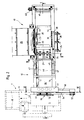
- the cutting station 1 indicated by dashed lines in FIGS. 1 and 2 essentially consists of a cutting machine 2, in the housing 3 of which a knife rotor 4 is overhung and on which the cutting knives are arranged in a ring shape.
- This knife ring 5 surrounds a cutting chamber 6, in which pressing elements 7 engage from above.
- the cutting machine 2 together with its drive motor 8 is mounted on a platform 9 which can be moved back and forth on rails 10.
- the wood located in the chipping chamber 6 is machined, after which the chipping chamber 6 is then made available again in the opposite direction for the next charging cycle at high speed.
- the homogeneous chip material produced leaves the housing 3 in the direction of a conveyor belt 11, which transports it away for immediate industrial processing.
- the cutting machine 2 described in rough outlines and not part of the actual invention is a so-called knife-ring cutter, but the feed device described below, designed according to the invention, can also be used for other types of cutting machines, such as cutter head or cutter disc cutters .
- the basic concept of the loading device according to the invention consists of a loading station 12 and a loading station 13.
- the main component of the loading station 12 is a gutter trough 14, which with its bottom surface 14 'ends at the same height in the cutting chamber 6 of the cutting machine 2 and whose cross-sectional profile essentially corresponds to the profile of the opened cutting chamber 6 by designing its side walls 15, 16.
- the one side wall 15 has a convex curvature with regard to the knife ring chipper 2 used here, the curvature of which corresponds to the inner radius of the knife ring 5.
- Above the mouth area of the channel trough 14 there is a pressure unit 17 which acts from above and which clamps the wood stack directly in front of the cutting chamber 6 from above during the individual cutting cycles.
- Another component of the loading station 12 is a closure slide 18 which can be inserted from the side between the channel trough 14 and the cutting chamber 6 and closes the cutting chamber 6 at the last cutting cycle.
- the loading station 13 arranged directly behind the loading station 12 in turn consists of a loading magazine 19 and a cross conveyor 20 assigned to it.
- the loading magazine 19 is flush with the cross section of the channel trough 14 and consequently forms its rear extension with its side walls 15 ', 16' and its bottom surface 19 ' .
- Channel trough 14 and loading magazine 19 are mounted on a common frame 21.
- a plurality of slots 22 are provided, in which directing and straightening elements 23, 24 can be moved into the loading magazine 19 from the side in order to combine the logs conveyed into the loading magazine 19 by the cross conveyor 20 to form parallel, tightly packed logs 25.
- the directing and straightening elements 23, 24 can be actuated by means of hydraulic units 26 via control linkages 27, 28.
- a common push plate 29 can be moved longitudinally in order to first of all form the wooden stack 25 formed in the loading magazine 19 into the trough trough 13 and from there in incremental sections into the cutting chamber 6 of the cutting machine 2 push.
- the number and size of the individual feed cycles are matched to the working width of the chipper in accordance with the greatest length of a wood stack in each case in such a way that an optimal degree of filling is achieved the cutting chamber 6 result in cutting sections of the same length, thereby avoiding the creation of residual sections during the last cutting cycle of a wood stack.
- the thrust plate 29 is shown in three positions, namely in its thrust position A and in dashed lines in its return position B and in its central position C during the pivoting.
- the push plate 29 is on three arms 30 of a two-armed lever system 31 are attached, on the other arms 32 a counterweight 33 and on both sides thereof a pair of control rollers 34 are arranged.
- the two-armed lever system 31 is mounted on a pivot axis 35 on an essentially flat plate which, together with laterally attached rollers 36, forms a support 37 which can be moved back and forth in guide grooves 38 running above the trough trough 14 and the loading magazine 19.
- the guide grooves 38 extend continuously from the channel trough 14 beyond the loading magazine 19.
- the back and forth movement of the support 37 is provided by a chain drive, which consists of two endless, synchronously driven chain hoists 39, the upper run of which is also accommodated in the guide grooves 38, while the lower run slides in the chain grooves 40 which slide on the inside of the Frame 21 are attached.
- the deflection of the two chain hoists 39 is provided by paired sprockets 42, a pair of which are connected to one another in a rotationally fixed manner by a connecting shaft 41 and can be driven by a controllable gear or hydraulic motor 43.
- the control rollers 34 of the thrust plate 29 interact briefly with stationary control tracks 44, 45, which are arranged in pairs on both sides of the mouth region of the channel trough 14 and at some distance behind the loading magazine 19.
- the two control tracks 44 assigned to the channel trough 14 are each formed from the underside of a control tongue 46 which is pivotally mounted on the inside of side cheeks 47, which are theirs are attached to the side edges of the gutter trough 14.
- the upper side of the two control tongues 46 form run-up surfaces 48 for the control rollers 34 which, when the thrust plate 29 in the thrust position A is moved forward, press the control tongues 46 downwards so far that they can pass freely in the direction of insertion.
- the other stationary control track 45 is mounted at the opposite end of the loading device at some distance behind the loading magazine 19 in order to enable the push plate 29 to pivot into its push position A behind the wood stack 25 provided in the loading magazine 19.
- the closure slide 18 provided between the mouth end of the channel trough 14 and the cutting chamber 6 is closed in FIGS. 1 and 2 and open in FIG. 4 State shown.
- the cutting chamber 6 of the cutting machine 2 can be closed after insertion of the last section of a wood stack, so that after the last insertion, the push plate 29 can be returned to its starting position at high speed without fear that during the Residual machining of wood from the machining chamber 6 are pushed back into the channel trough 14, which would lead to residual sections and thus to a deterioration in the quality of the chips.
- the closure slide 18 can be inserted from the side between the channel trough 14 and the cutting chamber 6. For this purpose, it is suspended at the top on rollers 52 and guided laterally at the bottom in a groove 53 provided in the bottom of the machining chamber 6.
- the rollers 52 run on a running rail 54 which is fastened to a flange 55 horizontally attached to the housing 3 of the cutting machine 2. Accordingly, the running rail 54 follows the to-and-fro movements of the cutting machine 2, while the closure slide 18, which is slidably suspended thereon, itself remains at rest.
- the slide valve 18 is actuated by a hydraulic system 56, which is supported on a bracket bearing 57, which in turn is attached to a cantilever arm 58 attached to the frame 21.
- the slide valve 18 After insertion of the last section of a wood stack, the slide valve 18 immediately closes the cutting chamber 6, while in the previous cutting cycles it acts as a pressure element with its reinforced front edge 60 around the wood stack during to hold the cutting cycles directly in front of the cutting chamber in cooperation with the opposite side wall 15 of the channel trough 14 from the side. Accordingly, its end edge 60 is concavely shaped to match the opposite convexly curved side wall 15 of the channel trough 14. In addition, the end edge 60 is provided with an inclined surface 61 facing the cutting chamber 6 in order to ensure a problem-free closing movement of the closure slide 18.
- the closing slide 18 in the closed state with its cover plate 59 serves as a stop for the wood stack 25 newly inserted into the channel trough 14. It thereby marks the starting position of the push plate 29 for the uniform feed cycles and at the same time gives the start signal for the restart of the cross conveyor 20.
- Fig. 5 illustrates the kinematic principle of action of the control mechanism for the pivoting movements of the push plate 29 from its push position A to its return position B and vice versa.
- the masses of the thrust plate 29 and counterweight 33 are dimensioned and arranged with respect to the pivot axis 35 of the two-armed lever system 31 such that in the central position C of the pivoting movement the overall center of gravity (center of mass) S of the two-armed lever system 31 is located exactly above the pivot axis 35. In this middle position C, the two-armed lever system 31 therefore assumes an unstable equilibrium position from which the Thrust plate 29 then tilts automatically into one of the two stable positions A or B, in which the center of gravity S occupies the positions S 'or S ⁇ .
- the loading device designed according to the invention works as follows:
- the logs delivered in uniform transport lengths of approximately 2.50 m are fed to the cross conveyor 20 by conveying devices, not shown, which individually transports the timbers into the loading magazine 19. There, the woods are formed into compact, parallel aligned stacks of wood 25 by correspondingly actuating the directing and straightening elements 23, 24. As soon as the loading magazine 19 is sufficiently filled, which can be signaled, for example, by an electronic light barrier, the cross conveyor 20 is stopped and the directing and straightening elements 23, 24 are moved completely out of the loading magazine 19.
- the push plate 29 has inserted the last section of the preceding stack of wood into the cutting chamber 6 and, after the slide valve 18 has closed the cutting chamber 6, it has returned to its starting position behind the loading magazine 19 while swiveling up to its return position B at high speed.
- the hydraulic systems of the pressure unit 17 acting from above and of the closing slide 18 pushing from the side are activated, and after reaching a predetermined contact pressure, the cutting machine 2 is then moved in the direction of the arrow shown in FIG Movement set, the constantly rotating knife ring 5 cutting the wood section located in the cutting chamber 6. Thereafter, the cutting machine 2 is moved back to its original position in rapid traverse and, after the pressure unit 17 and the closing slide 18 have been relaxed, the cutting chamber 6 is loaded again.
- the slide valve 18 is then pushed in front of the cutting chamber 6 and at the same time the push plate 29 immediately swiveled back to its return position B in rapid traverse to its starting position.
- the loading magazine 19 is refilled with the next wood stack, so that the work cycle can start again in the manner described.
- the mode of operation of the loading device designed according to the invention is independent of which type of cutting machine is loaded with it.
- a knife head chipper or a knife disk chipper can therefore also be used, only in the latter case the thrust plate 29 and the locking slide 18 having a concave curvature corresponding to the radius of the knife disk.
Landscapes
- Engineering & Computer Science (AREA)
- Mechanical Engineering (AREA)
- Life Sciences & Earth Sciences (AREA)
- Manufacturing & Machinery (AREA)
- Wood Science & Technology (AREA)
- Forests & Forestry (AREA)
- Chutes (AREA)
- Feeding Of Articles To Conveyors (AREA)
- Stacking Of Articles And Auxiliary Devices (AREA)
- Manufacture Of Wood Veneers (AREA)
- Debarking, Splitting, And Disintegration Of Timber (AREA)
- Manufacturing Of Cigar And Cigarette Tobacco (AREA)
Applications Claiming Priority (2)
| Application Number | Priority Date | Filing Date | Title |
|---|---|---|---|
| DE3923264 | 1989-07-14 | ||
| DE3923264A DE3923264A1 (de) | 1989-07-14 | 1989-07-14 | Beschickvorrichtung fuer holzzerspanungsmaschinen |
Publications (3)
| Publication Number | Publication Date |
|---|---|
| EP0407885A2 EP0407885A2 (de) | 1991-01-16 |
| EP0407885A3 EP0407885A3 (en) | 1991-08-28 |
| EP0407885B1 true EP0407885B1 (de) | 1993-11-10 |
Family
ID=6385003
Family Applications (1)
| Application Number | Title | Priority Date | Filing Date |
|---|---|---|---|
| EP90112812A Expired - Lifetime EP0407885B1 (de) | 1989-07-14 | 1990-07-05 | Beschickvorrichtung für Holzzerspanungsmaschinen |
Country Status (7)
| Country | Link |
|---|---|
| US (1) | US5070918A (enExample) |
| EP (1) | EP0407885B1 (enExample) |
| CA (1) | CA2015038C (enExample) |
| DE (1) | DE3923264A1 (enExample) |
| ES (1) | ES2045662T3 (enExample) |
| FI (1) | FI89880C (enExample) |
| PL (1) | PL162987B1 (enExample) |
Cited By (1)
| Publication number | Priority date | Publication date | Assignee | Title |
|---|---|---|---|---|
| CN106239676A (zh) * | 2016-08-24 | 2016-12-21 | 刘书雄 | 一种单板旋切机辅助用推动装置 |
Families Citing this family (26)
| Publication number | Priority date | Publication date | Assignee | Title |
|---|---|---|---|---|
| DE9306508U1 (de) * | 1993-04-30 | 1993-07-01 | Paper Converting Machine Gmbh, 6707 Schifferstadt | Vorrichtung zum Transport von Produkten |
| US5392829A (en) * | 1994-03-03 | 1995-02-28 | Cae Machinery, Ltd. | Apparatus and method for loading of logs |
| DE19500960C1 (de) * | 1995-01-14 | 1995-08-31 | Inter Wood Maschinen | Langholzzerspaner |
| DE19501102C1 (de) * | 1995-01-17 | 1996-05-23 | Jenoptik Technologie Gmbh | Verfahren und Vorrichtung zum kontinuierlichen Beschicken von Zerspanungsmaschinen zum reststückfreien Zerspanen von Stückholz gleicher Länge |
| EP0747146B1 (de) * | 1995-05-27 | 1998-05-06 | SMS Eumuco GmbH | Vorrichtung zum Laden von Blöcken und gegebenenfalls Pressscheiben in liegende Metallstrangpressen |
| US5755917A (en) * | 1996-08-20 | 1998-05-26 | Macmillan Bloedel Limited | Manufacture of consolidated composite wood products |
| US5957178A (en) * | 1997-11-20 | 1999-09-28 | Arasmith; Stanley Dale | Method and apparatus for processing pan-shaped wood members |
| US6125897A (en) * | 1997-12-22 | 2000-10-03 | Arasmith; Stanley Dale | Method and apparatus for processing pan-shaped wood members |
| AT407623B (de) * | 1999-03-12 | 2001-05-25 | Pietsch Georg Mag | Anlage zum stapeln von rundholz |
| US6575066B2 (en) | 2000-03-14 | 2003-06-10 | Stanley D. Arasmith | Method and apparatus for reducing oversized wood chips |
| US6510880B2 (en) | 2000-04-19 | 2003-01-28 | Stanley Dale Arasmith | Lumber trim end chipper |
| DE10047265C2 (de) * | 2000-09-23 | 2002-10-24 | Siempelkamp Gmbh & Co Kg G | Verfahren und Vorrichtung zum Herstellen von Strands |
| US7143796B2 (en) * | 2002-08-26 | 2006-12-05 | Arasmith Stanley D | Wood-reducing apparatus with continual feeder assembly |
| DE10300440B3 (de) * | 2003-01-09 | 2004-07-15 | Inter-Wood Maschinen Kg | Verfahren und Vorrichtung zum Herstellen von Furnierstreifen, Spänen oder dergleichen |
| DE102004025323A1 (de) * | 2003-05-23 | 2005-02-17 | Siempelkamp Maschinen- Und Anlagenbau Gmbh & Co. Kg | Vorrichtung zum Zerspanen von Schnittholzpaketen zu Strands |
| DE102010038212B4 (de) | 2010-10-15 | 2015-07-30 | Glunz Ag | Verfahren und Vorrichtung zum Zerspanen von Baumstämmen |
| AT514621B1 (de) * | 2013-07-29 | 2015-04-15 | Posch Gmbh | Vorrichtung zum Schneiden von Holz |
| USD742445S1 (en) * | 2014-05-30 | 2015-11-03 | OOTOYA Holdings Co., Ltd. | Flaking machine |
| US10434679B2 (en) * | 2016-06-09 | 2019-10-08 | Newman Machine Company, Inc. | Stationary box lumber shaving mill with a lumber arrestor |
| CN107791346A (zh) * | 2016-08-31 | 2018-03-13 | 天津市鹏川科技发展有限公司 | 压门机 |
| CN107826682A (zh) * | 2017-12-05 | 2018-03-23 | 重庆市远望谷科技有限公司 | 一种pcb印制板夹持器 |
| CN110050663B (zh) * | 2019-05-22 | 2021-06-22 | 安徽森米诺农业科技有限公司 | 一种咬合推送的杉树原木切断分离一体机 |
| CN112645020B (zh) * | 2020-12-22 | 2021-12-14 | 江苏省镔鑫钢铁集团有限公司 | 一种韩标sd600盘螺钢及其生产方法及制备装置 |
| CN113246241B (zh) * | 2021-05-28 | 2022-11-29 | 成都安居天下实业有限责任公司 | 一种双侧榫头一体化加工系统 |
| CN116551794B (zh) * | 2023-05-24 | 2025-06-24 | 陕西森盛菌业科技有限公司 | 食用菌制种用的木条制作旋切机 |
| CN117067339A (zh) * | 2023-09-05 | 2023-11-17 | 湖北宝源木业有限公司 | 刨花机的理料进给系统及方法 |
Family Cites Families (4)
| Publication number | Priority date | Publication date | Assignee | Title |
|---|---|---|---|---|
| BE648105A (enExample) * | ||||
| DE2213618A1 (de) * | 1972-03-21 | 1973-10-25 | Paul Dr Ing Kirsten | Langholzspanungsmaschine fuer die holzspanplattenindustrie |
| DE3611866A1 (de) * | 1986-04-09 | 1987-10-15 | Pallmann Kg Maschf | Verfahren und vorrichtung zum beschicken von zerspanern mit stueckholz einheitlicher laenge |
| US4865094A (en) * | 1988-10-24 | 1989-09-12 | Cae Machinery Ltd. | Long log waferizer |
-
1989
- 1989-07-14 DE DE3923264A patent/DE3923264A1/de active Granted
-
1990
- 1990-04-20 CA CA002015038A patent/CA2015038C/en not_active Expired - Lifetime
- 1990-05-03 US US07/519,224 patent/US5070918A/en not_active Expired - Lifetime
- 1990-07-05 EP EP90112812A patent/EP0407885B1/de not_active Expired - Lifetime
- 1990-07-05 ES ES90112812T patent/ES2045662T3/es not_active Expired - Lifetime
- 1990-07-11 FI FI903514A patent/FI89880C/fi active IP Right Grant
- 1990-07-12 PL PL28603990A patent/PL162987B1/pl unknown
Cited By (1)
| Publication number | Priority date | Publication date | Assignee | Title |
|---|---|---|---|---|
| CN106239676A (zh) * | 2016-08-24 | 2016-12-21 | 刘书雄 | 一种单板旋切机辅助用推动装置 |
Also Published As
| Publication number | Publication date |
|---|---|
| DE3923264A1 (de) | 1991-01-17 |
| FI903514A0 (fi) | 1990-07-11 |
| FI89880C (fi) | 1993-12-10 |
| CA2015038A1 (en) | 1991-01-14 |
| DE3923264C2 (enExample) | 1991-07-11 |
| FI89880B (fi) | 1993-08-31 |
| EP0407885A2 (de) | 1991-01-16 |
| PL162987B1 (pl) | 1994-01-31 |
| CA2015038C (en) | 1993-11-02 |
| ES2045662T3 (es) | 1994-01-16 |
| PL286039A1 (en) | 1991-02-25 |
| US5070918A (en) | 1991-12-10 |
| EP0407885A3 (en) | 1991-08-28 |
Similar Documents
| Publication | Publication Date | Title |
|---|---|---|
| EP0407885B1 (de) | Beschickvorrichtung für Holzzerspanungsmaschinen | |
| DE1632165B2 (de) | Vorratsbehaelter mit veraenderlichem fassungsvermoegen fuer stabfoermige gegenstaende | |
| DE2125991A1 (de) | Verfahren und Vorrichtung zum Transport gestapelter flacher Gegenstände in Aufeinanderfolge zu einem Auffangen | |
| DE2127310C3 (de) | Fördereinrichtung für Flaschen oder ähnliches Fördergut | |
| DE2603165A1 (de) | Foerderanlage mit foerderstiften fuer werkstuecke mit oeffnungen | |
| DE2445330C3 (de) | Fördererschuß mit einer Gleit- und Führungsbahn für eine Gewinnungsmaschine | |
| DE2012615B2 (de) | Schubvorrichtung zum absatzweisen Zuführen und Ausstoßen einzelner Reihen von Behältern für Gefrieranlagen | |
| DE2435200C2 (de) | Fördervorrichtung für eine Ziegelherstellmaschine | |
| AT394703B (de) | Selbstfahrender wagen | |
| DE2152727C3 (de) | Vorrichtung zur automatischen Entstapelung und Zuführung von Brettern zu einer Bearbeitungsmaschine | |
| DE19534954A1 (de) | Hochspeicher für Werkstücke und Verfahren zum Betreiben eines Hochspeichers | |
| DE10051790A1 (de) | Behälter, Vorrichtung und Verfahren zum Transportieren von stabförmigen Artikeln der tabakverarbeitenden Industrie | |
| DE3327747A1 (de) | Vorrichtung zum zufuehren von stangenfoermigem stueckgut | |
| DE2130795A1 (de) | Verfahren und vorrichtung zum ablaengen von langem stammholz | |
| DE4015572C2 (de) | Beschickungseinrichtung für eine Maschine zum Zusammensetzen von Furnierstreifen zu einer Furnierbahn | |
| DE2618568A1 (de) | Zufuehr-vorrichtung fuer materialstaebe | |
| DE2724284A1 (de) | Beladevorrichtung | |
| DE1581087A1 (de) | Foerdereinrichtung zum Befoerdern von aus mindestens zwei Maschinen austretenden Gegenstaenden zu einer nachgeschalteten Maschine | |
| DE2604973C3 (de) | Flaschenauspackmaschine | |
| DE1127275B (de) | Einrichtung zum selbsttaetigen Zufuehren von flachen Gegenstaenden, insbesondere Biskuits, zu einer Verpackungsmaschine | |
| DE3490626C2 (enExample) | ||
| DE2535064A1 (de) | Abgabevorrichtung fuer gefaesse aus reinigungsmaschinen | |
| DE2152392A1 (de) | Geraet zum stapeln oder abstapeln von platten | |
| DE1556588A1 (de) | Schraegfoerderer | |
| DE3629802A1 (de) | Magazin fuer eine kartonzuschnitte verarbeitende maschine |
Legal Events
| Date | Code | Title | Description |
|---|---|---|---|
| PUAI | Public reference made under article 153(3) epc to a published international application that has entered the european phase |
Free format text: ORIGINAL CODE: 0009012 |
|
| AK | Designated contracting states |
Kind code of ref document: A2 Designated state(s): ES FR IT SE |
|
| PUAL | Search report despatched |
Free format text: ORIGINAL CODE: 0009013 |
|
| AK | Designated contracting states |
Kind code of ref document: A3 Designated state(s): ES FR IT SE |
|
| 17P | Request for examination filed |
Effective date: 19911008 |
|
| 17Q | First examination report despatched |
Effective date: 19921105 |
|
| GRAA | (expected) grant |
Free format text: ORIGINAL CODE: 0009210 |
|
| AK | Designated contracting states |
Kind code of ref document: B1 Designated state(s): ES FR IT SE |
|
| REG | Reference to a national code |
Ref country code: ES Ref legal event code: FG2A Ref document number: 2045662 Country of ref document: ES Kind code of ref document: T3 |
|
| ITF | It: translation for a ep patent filed | ||
| ET | Fr: translation filed | ||
| PLBE | No opposition filed within time limit |
Free format text: ORIGINAL CODE: 0009261 |
|
| STAA | Information on the status of an ep patent application or granted ep patent |
Free format text: STATUS: NO OPPOSITION FILED WITHIN TIME LIMIT |
|
| 26N | No opposition filed | ||
| EAL | Se: european patent in force in sweden |
Ref document number: 90112812.4 |
|
| PGFP | Annual fee paid to national office [announced via postgrant information from national office to epo] |
Ref country code: IT Payment date: 20090624 Year of fee payment: 20 |
|
| PGFP | Annual fee paid to national office [announced via postgrant information from national office to epo] |
Ref country code: FR Payment date: 20090722 Year of fee payment: 20 Ref country code: ES Payment date: 20090724 Year of fee payment: 20 |
|
| PGFP | Annual fee paid to national office [announced via postgrant information from national office to epo] |
Ref country code: SE Payment date: 20090730 Year of fee payment: 20 |
|
| REG | Reference to a national code |
Ref country code: ES Ref legal event code: FD2A Effective date: 20100706 |
|
| EUG | Se: european patent has lapsed | ||
| PG25 | Lapsed in a contracting state [announced via postgrant information from national office to epo] |
Ref country code: ES Free format text: LAPSE BECAUSE OF EXPIRATION OF PROTECTION Effective date: 20100706 |