EP0378219B1 - Système de suspension pour véhicule - Google Patents
Système de suspension pour véhicule Download PDFInfo
- Publication number
- EP0378219B1 EP0378219B1 EP90100542A EP90100542A EP0378219B1 EP 0378219 B1 EP0378219 B1 EP 0378219B1 EP 90100542 A EP90100542 A EP 90100542A EP 90100542 A EP90100542 A EP 90100542A EP 0378219 B1 EP0378219 B1 EP 0378219B1
- Authority
- EP
- European Patent Office
- Prior art keywords
- suspension system
- vehicle
- upper arm
- wheel
- vehicle suspension
- Prior art date
- Legal status (The legal status is an assumption and is not a legal conclusion. Google has not performed a legal analysis and makes no representation as to the accuracy of the status listed.)
- Expired - Lifetime
Links
Images


Classifications
-
- B—PERFORMING OPERATIONS; TRANSPORTING
- B60—VEHICLES IN GENERAL
- B60G—VEHICLE SUSPENSION ARRANGEMENTS
- B60G3/00—Resilient suspensions for a single wheel
- B60G3/18—Resilient suspensions for a single wheel with two or more pivoted arms, e.g. parallelogram
- B60G3/20—Resilient suspensions for a single wheel with two or more pivoted arms, e.g. parallelogram all arms being rigid
- B60G3/202—Resilient suspensions for a single wheel with two or more pivoted arms, e.g. parallelogram all arms being rigid having one longitudinal arm and two parallel transversal arms, e.g. dual-link type strut suspension
- B60G3/205—Resilient suspensions for a single wheel with two or more pivoted arms, e.g. parallelogram all arms being rigid having one longitudinal arm and two parallel transversal arms, e.g. dual-link type strut suspension with the pivotal point of the longitudinal arm being on the vertical plane defined by the wheel rotation axis and the wheel ground contact point
-
- B—PERFORMING OPERATIONS; TRANSPORTING
- B60—VEHICLES IN GENERAL
- B60G—VEHICLE SUSPENSION ARRANGEMENTS
- B60G2200/00—Indexing codes relating to suspension types
- B60G2200/10—Independent suspensions
- B60G2200/17—Independent suspensions with a strut contributing to the suspension geometry by being articulated onto the wheel support
-
- B—PERFORMING OPERATIONS; TRANSPORTING
- B60—VEHICLES IN GENERAL
- B60G—VEHICLE SUSPENSION ARRANGEMENTS
- B60G2200/00—Indexing codes relating to suspension types
- B60G2200/40—Indexing codes relating to the wheels in the suspensions
- B60G2200/46—Indexing codes relating to the wheels in the suspensions camber angle
-
- B—PERFORMING OPERATIONS; TRANSPORTING
- B60—VEHICLES IN GENERAL
- B60G—VEHICLE SUSPENSION ARRANGEMENTS
- B60G2200/00—Indexing codes relating to suspension types
- B60G2200/40—Indexing codes relating to the wheels in the suspensions
- B60G2200/462—Toe-in/out
-
- B—PERFORMING OPERATIONS; TRANSPORTING
- B60—VEHICLES IN GENERAL
- B60G—VEHICLE SUSPENSION ARRANGEMENTS
- B60G2204/00—Indexing codes related to suspensions per se or to auxiliary parts
- B60G2204/40—Auxiliary suspension parts; Adjustment of suspensions
- B60G2204/422—Links for mounting suspension elements
Definitions
- the present invention relates to a vehicle suspension system according to the preamble of claim 1.
- a vehicle suspension system according to the preamble of claim 1.
- Such a suspension is known e.g. form the DE-OS 2255679.
- Japanese Utility Model Public Disclosure No. 62-187904 laid open to the public in 1987 (corresponding to U.S. Patent No. 4,570,968), discloses so called "double wishbone” type vehicle suspension system which is provided with an A-shaped upper and lower arms for carrying vehicle wheels.
- Such double wish bone type suspension is advantageous in the point of suppressing a squat at the time of starting vehicle, a change in camber and the like.
- the double wish bone type suspension is disadvantageous in the point of deteriorating a riding comfort, and producing a brake judder.
- Japanese Utility Model Publication No. 62-1762 published for opposition in 1987 discloses so called "high mount double wish bone" type vehicle suspension.
- An upper arm of the suspension as disclosed in Japanese Utility Model Public Disclosure No. 62-1762 is relatively short and disposed oblique to the vehicle wheels in an up and down direction. As a result, the movement of the vehicle wheels is restricted in the up and down direction. Furthermore, a camber angle change may be unduly increased.
- the extension is of such an inwardly arcuate configuration that extends upwardly along an inside of a tire of the wheel.
- An upper end of the extension may be projected beyond an upper end of the tire of the wheel in a preferred embodiment.
- An upper end portion of the extension may be arched outwardly.
- the first upper arm member may be pivotally connected at a front end with the upper end portion of the extension and at a rear end with the vehicle body member.
- This invention can be suitably applied for both a front and rear suspension systems.
- the first upper arm member extend forwardly upwardly in the front suspension system.
- the first upper arm member may be pivotally connected at a front end with the vehicle body member and at a rear end with the wheel carrying member.
- the first upper arm member extends rearwardly upwardly in the rear suspension system.
- the second upper arm member is pivotally connected at an inner end with the vehicle body member and at an outer end with the wheel carrying means.
- the connection of the outer end with the wheel carrying member is located at a position higher than a wheel carrying portion of the wheel carrying means and lower than an upper end of a rim of the wheel wherein the wheel carrying means rotatably carries the wheel by the wheel carrying portion.
- the first and second upper arm members are preferably provided with means for adjusting the length thereof respectively, for example turnbuckle.
- the lower arm means may be of an A-shaped configuration.
- the lower arm means is pivotally connected at biforked inner ends with the vehicle body member and at a single outer end with the wheel carrying means.
- the connecting points between the wheel carrying means and the first upper arm member, between the wheel carrying means and the second upper arm member, and between the wheel carrying means and the lower arm means are substantially on a single straight line.
- the suspension system may further comprise link means for restricting a pivotal movement of the wheel about said straight line, such as a tie rod controlled by a steering control device.
- the lower arm means may include a pair of lower arm members extending substantially transversely and a trailing link extending substantially longitudinally.
- the suspension system may further comprise shock absorber for absorbing an impact load in an up and down direction.
- the shock absorber is disposed opposite to the first upper arm member with regard to the second upper arm means in the longitudinal direction.
- the shock absorbing means comprises a coil spring and a damper.
- the first upper arm member is arranged away from the wheel carrying means enough to provide a bushing between the first upper arm member and the wheel carrying means with a soft property. As a result, an improved riding comfort can be obtained and the brake judder can be suppressed effectively.
- the second upper arm which controls the transverse movement of the wheel carrying means can provide with a desirable camber angle change property in association with the lower arm means.
- the length of the second upper arm member can be increased to provide an improved camber angle change property in case of bumping and rebounding action of the vehicle.
- the upper arm means is constituted by only one pair of arm members not by the A-shaped arm so that a layout of the members of the suspension can be facilitated. Since the first and second upper members are independent from each other, the camber and caster can be controlled separately. The inclination of the first upper arm provides with anti-diving effect in front wheels and anti-lifting effect in rear wheels.
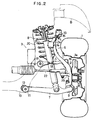
- FIG. 1 a vehicle right front suspension system in accordance with a preferred embodiment of the present invention.
- a right front wheel 1 is rotatably carried by a suspension carrying member 2 and connected to a vehicle body B through a suspension system 3.
- the wheel carrying member 2 is provided with an extension 2a of an arcuate configuration extending upwardly along an inside of the wheel 1 beyond an upper end of a rim 1a, preferably an upper end of a tire.
- the extension 2a extends at first upwardly inwardly in a base portion thereof and then upwardly outwardly in an upper end portion.
- the suspension system 3 comprises an upper arm device 6 having a first upper arm 4 and a second upper arm 5 as link members, an A-shaped lower arm 7 and a shock absorber 8.
- the lower arm 7 extending substantially in a transverse direction of a vehicle is connected at a converged outer end thereof to a lower end of the wheel carrying member 2 for a swingable movement about a substantially vertical axis through a rubber bushing 9.
- Biforked inner ends of the lower arm 7 are connected to a cross member of the body B through rubber bushings 11 and 12 for a swingable movement about a horizontal axis extending in a longitudinal direction of the vehicle.
- the rubber bushings 11 and 12 are arranged in parallel with a vehicle center line in the longitudinal direction.
- the first upper arm 4 extends substantially rearwardly from the wheel carrying member 2 in the longitudinal direction above the upper end of the rim 1a of the wheel 1.
- the first upper arm 4 which functions to restrict a longitudinal movement of the wheel carrying member 2 is connected at a front end with the extension 2a through a rubber bushing 13 for a pivotal movement about a vertical axis and at a rear end with the vehicle body B through a rubber bushing 14 for a pivotal movement about a horizontal axis.
- the first upper arm 4 slightly inclines rearwardly downwardly.
- This inclination of the arm 4 effects to position an instantaneous center of the pivotal movement of the wheel carrying member 2 at a rear side of a wheel rotation center wherein the instantaneous center is defined by an attitude of the arm 4 and a line passing the rubber bushings 11 and 12 of the lower arm 7. This produces an anti-diving effect at the time of braking condition of the vehicle.
- the arm 4 is provided at an intermediate portion with a turnbuckle for adjusting the caster angle of the wheel 1.
- the second upper arm 5 extends substantially transversely for restricting a transverse movement of the wheel carrying member 2.
- the second upper arm 5 is connected at an outer end with the wheel carrying member 2 through a rubber bushing 16 for a pivotal movement about a substantially vertical axis and at an inner end with the cross member 10 through a rubber bushing 17 for a pivotal movement about a longitudinally extending horizontal axis.
- the joint between the outer end of the arm 5 and the wheel carrying member 2 is located lower than the upper end of the rim 1a.
- the length of the second upper arm 5 is substantially equal to that in an uneven length type of conventional double wishbone suspension system, and longer than an upper arm disclosed in the Japanese Utility Model publication No. 62-1762.
- the second upper arm 5 is provided at an intermediate portion with a turnbuckle 18 so as to adjust the camber angle of the wheel 1.
- the wheel carrying member 2 is provided with a knuckle portion 2b extending inwardly rearwardly to which a tie rod 22 is pivotally connected about a substantially vertical axis.
- the rubber bushing 9 disposed at an outer connecting point between the lower arm member 7 and the wheel carrying member 2, the rubber bushing 13 disposed at an outer connecting point between the first upper arm member 4 and the wheel carrying member 2 and the rubber bushing 16 disposed at an outer connecting point between the second upper arm member 5 and the wheel carrying member 2 are located to be substantially on a single straight line.
- the tie rod 22 is controlled by a steering control device to provide the wheel 1 with a pivotal movement about the single straight line as a pivotal axis of a steering action.
- the shock absorber 8 extends in the up and down direction and is provided with a coil spring 20 and a damper 21.
- the shock absorber 8 is connected at a lower end with the lower arm 7 for a pivotal movement about a substantially longitudinally extending horizontal axis and at an upper end with the vehicle body B for a slightly pivotal movement about its axis.
- the first upper arm 4 is disposed upper than the upper end of the rim 1a so that a distance between the joint of the arm 4 with the wheel carrying member and the rotation center of the wheel 1 is increased. This enables the bushing 14 between the vehicle body B and the arm 4 to be softer in rigidity to thereby improve the riding comfort and suppress the brake judder.
- the first upper arm 4 extends substantially longitudinally and is provided with the turnbuckle 15 for adjusting the caster angle of the wheel 1.
- the second upper arm 5 extends substantially transversely and is provided with the turnbuckle 18 for adjusting the camber angle of the wheel 1. It will therefore be understood that the respective adjustments for the caster and camber angles are not influenced by each other.
- the first and second upper arms 4 and 5 are separated as aforementioned to facilitate a layout therefor.
- the second upper arm 5 is disposed at a position lower than the upper end of the rim 1a where there is a space extending horizontally. This enables the second upper arm 5 to have a length enough to provide a desirable camber angle change property for the wheel 1.
- the present invention is applied to a right rear suspension.
- a right rear wheel 31 is rotatably carried by a suspension carrying member 32 and connected to a vehicle body B1 through a suspension system 33.
- the wheel carrying member 32 is provided with an extension 32a extending upwardly along an inside of the wheel 31 beyond an upper end of a rim 31a.
- the suspension system 33 comprises an upper arm device 36 having a first upper arm 34 and a second upper arm 35 as link members, a lower arm device 39 including a first lower arm 37 and a second lower arm 38, a trailing arm 40 and a shock absorber 41.
- the first and second lower arms 37 and 38 of the lower arm device 39 extending substantially transversely are connected at outer ends to lower ends of the wheel carrying member 2 for swingable movements about substantially horizontal axes through rubber bushings 42 and 43 and at inner ends with a cross member 44 through rubber bushings 45 and 46 for swingable movements about substantially longitudinally extending horizontal axes.
- the rubber bushings 45 and 46 are arranged in parallel with the vehicle center line in the longitudinal direction.
- the first upper arm 34 extends substantially forwardly from the wheel carrying member 32 in the longitudinal direction above the upper end of the rim 31a of the wheel 31.
- the first upper arm 34 which functions to restrict a longitudinal movement of the wheel carrying member 32 is connected at a front end with the extension 32a through a rubber bushing 47 for a pivotal movement about a vertical axis and at a rear end with the vehicle body B1 through a rubber bushing 48 for a pivotal movement about a horizontal axis.
- the first upper arm 34 slightly inclines forwardly downwardly.
- This inclination of the arm 34 effects to position an instantaneous center of the pivotal movement of the wheel carrying member 32 at a front side of the wheel rotation center wherein the instantaneous center is defined by an attitude of the arm 34 and a line connecting the rubber bushings 45 and 46 for the lower arm 39. This results in an anti-lifting effect at the time of braking condition of the vehicle.
- the second upper arm 35 extends substantially transversely for restricting a transverse movement of the wheel carrying member 32.
- the second upper arm 35 is connected at an outer end with the wheel carrying member 32 through a rubber bushing 49 for a pivotal movement about a substantially longitudinally extending horizontal axis and at an inner end with the cross member 44 through a rubber bushing 50 for a pivotal movement about a longitudinally extending horizontal axis.
- the joint between the outer end of the arm 35 and the wheel carrying member 32 is located lower than the upper end of the rim 31a.
- the length of the second upper arm 35 is substantially equal to that in an uneven length type of conventional double wishbone suspension system, and longer than an upper arm disclosed in the Japanese Utility Model publication No. 62-1762.
- the shock absorber 41 extends in the up and down direction and is provided with a coil spring 51 and a damper 52.
- the shock absorber 41 is connected at a lower end with the wheel carrying member 32 for a pivotal movement about a substantially transversely extending horizontal axis and at an upper end with the vehicle body B1 for a slightly pivotal movement about its axis.
- the trailing link 40 is connected at a rear end with the wheel carrying member 32 through a rubber bushing 53 for a pivotal movement about a substantially transversely extending horizontal axis and at a front end with the vehicle body B1 for a pivotal movement about a substantially transversely extending horizontal axis.
- FIG. 7 there is shown further embodiment of the present invention applied for a left front wheel 1.
- This structure is preferably applied for the front suspension system.
- the lower arm device 7 is constituted by a pair of link members 7a, 7b.
- the link member 7b is connected with an intermediate portion of the link member 7a. The same effect as the first mentioned embodiment can be obtained.
- the link member 7b is not connected with the link member 7a but with the wheel carrying member 2.
- Figure 9 shows yet another embodiment for the left front suspension.
- the first upper arm 4 extends forwardly upwardly from the extension 2a.
- Figure 10 shows another embodiment for the left rear suspension.
- the trailing arm 40 extends longitudinally and is connected with an intermediate portion of the first lower arm 38 for a swingable movement in the up and down direction.
- the lower arm device 39 is constituted by an A-shaped arm.
- the lower arm device 39 is connected at an outer end with the wheel carrying member 32 and at inner ends with the vehicle body B1 for a swingable movement in the up and down direction.
- the rear suspension system 33 is provided with a toe control link 55 extending substantially transversely.
- the control link 55 is connected with a rear biforked portion of the lower arm device 39 at inner end for a swingable movement in a substantially horizontal plane and with a rear end portion of the wheel carrying member 32 at an outer end.
- the first upper arm 34 may extend forwardly downwardly so that the instantaneous center of the pivotal movement of the wheel 31 in a horizontal plane is located at a position forward of the wheel center.
- first upper arm 34 extends rearwardly upwardly from the wheel carrying member 32 and the second lower arm 40 also extends rearwardly inwardly from the wheel carrying member 32 so that the instantaneous center of the wheel 31 is located forward of the wheel center.
Landscapes
- Engineering & Computer Science (AREA)
- Mechanical Engineering (AREA)
- Vehicle Body Suspensions (AREA)
Claims (19)
- Système de suspension de véhicule comportant :(a) des moyens de support de roue (2) destinés à supporter de façon rotative une roue (1) d'un véhicule, les moyens de support de roue (2) étant pourvus d'une extension (2a) s'étendant vers le haut;(b) un premier élément de bras supérieur (4) s'étendant dans une direction sensiblement longitudinale du véhicule et relié de façon pivotante à une extrémité à une partie supérieure de ladite extension (2a) et à l'autre extrémité à un élément de caisse de véhicule (B);(c) un deuxième élément de bras supérieur (5) s'étendant dans une direction sensiblement transversale du véhicule et relié de façon pivotante à une extrémité aux moyens de support de roue (2) et à l'autre extrémité à l'élément de caisse de véhicule (B);(d) des moyens de bras inférieur (7) reliés à une extrémité à une partie inférieure des moyens de support de roue (2) et à l'autre extrémité à l'élément de caisse de véhicule (B) afin de limiter au moins un mouvement transversal et longitudinal des moyens de support de roue (2),
caractérisé en ce que
le deuxième élément de bras supérieur (5) est relié aux dits moyens de support de roue (2) dans une position vers le bas par rapport au premier élément de bras supérieur (4). - Système de suspension de véhicule selon la revendication 1, dans lequel l'extension (2a) est d'une configuration courbe vers l'intérieur telle qu'elle s'étend vers le haut le long d'un côté intérieur d'un pneumatique de la roue (1).
- Système de suspension de véhicule selon la revendication 2, dans lequel une extrémité supérieure de l'extension (2a) dépasse au-delà d'une extrémité supérieure du pneumatique de la roue.
- Système de suspension de véhicule selon la revendication 3, dans lequel une partie d'extrémité supérieure de l'extension (2a) est recourbée vers l'extérieur.
- Système de suspension de véhicule selon la revendication 1, dans lequel le premier élément de bras supérieur (4) est relié de façon pivotante à une extrémité avant à la partie d'extrémité supérieure de l'extension et à une extrémité arrière à l'élément de caisse de véhicule.
- Système de suspension de véhicule selon la revendication 5, dans lequel le système de suspension est un système de suspension avant.
- Système de suspension de véhicule selon la revendication 6, dans lequel le premier élément de bras supérieur (4) s'étend vers l'avant et vers le haut.
- Système de suspension de véhicule selon la revendication 1, dans lequel le premier élément de bras supérieur (4) est relié de façon pivotante à une extrémité avant à l'élément de caisse de véhicule (B) et à une extrémité arrière à l'élément de support de roue (2).
- Système de suspension de véhicule selon la revendication 8, dans lequel le système de suspension est un système de suspension arrière.
- Système de suspension de véhicule selon la revendication 9, dans lequel le premier élément de bras supérieur (4) s'étend vers l'arrière et vers le haut.
- Système de suspension de véhicule selon la revendication 1, dans lequel le deuxième élément de bras supérieur (5) est relié de façon pivotante à une extrémité interne à l'élément de caisse de véhicule (B) et à une extrémité externe aux moyens de support de roue (2), la liaison de l'extrémité externe à l'élément de support de roue se trouvant dans une position plus haute qu'une partie de support de roue des moyens de support de roue (2) et plus basse qu'une extrémité supérieure d'une jante (1a) de la roue.
- Système de suspension de véhicule selon la revendication 1, dans lequel les premier et deuxième éléments de bras supérieur (4, 5) sont pourvus de moyens destinés à régler leur longueur de manière respective.
- Système de suspension de véhicule selon la revendication 1, dans lequel les moyens de bras inférieur (7) ont une configuration en forme de A, les moyens de bras inférieur (7) étant reliés de façon pivotante aux extrémités internes en forme de fourche à l'élément de caisse de véhicule (B) et à une extrémité extérieure simple aux moyens de support de roue (2).
- Système de suspension de véhicule selon la revendication 13, dans lequel des points de liaison entre les moyens de support de roue (2) et le premier élément de bras supérieur (4), le deuxième élément de bras supérieur (5) et les moyens de bras inférieur (7) se trouvent sensiblement sur une unique ligne droite.
- Système de suspension de véhicule selon la revendication 14, comportant en outre des moyens de liaison (22) destinés à limiter un mouvement pivotant de la roue autour de ladite ligne droite.
- Système de suspension de véhicule selon la revendication 14, dans lequel les moyens de liaison sont constitués par une biellette (22) qui dirige les roues grâce à un dispositif de direction.
- Système de suspension de véhicule selon la revendication 1, dans lequel lesdits moyens de bras inférieur (7) comportent une paire d'éléments de bras inférieur s'étendant sensiblement transversalement et un bras tiré (40) s'étendant sensiblement longitudinalement.
- Système de suspension de véhicule selon la revendication 1, comportant en outre des moyens amortisseurs (8) destinés à absorber une charge d'impact dans une direction vers le haut et vers le bas, les moyens amortisseurs (8) étant disposés à l'opposé du premier élément de bras supérieur par rapport aux deuxième moyens de bras supérieur dans la direction longitudinale.
- Système de suspension de véhicule selon la revendication 18, dans lequel les moyens amortisseurs (8) comportent un ressort hélicoïdal (20) et un amortisseur (21).
Applications Claiming Priority (2)
| Application Number | Priority Date | Filing Date | Title |
|---|---|---|---|
| JP4873/89 | 1989-01-13 | ||
| JP1004873A JP2714969B2 (ja) | 1989-01-13 | 1989-01-13 | 自動車のサスペンション装置 |
Publications (3)
| Publication Number | Publication Date |
|---|---|
| EP0378219A2 EP0378219A2 (fr) | 1990-07-18 |
| EP0378219A3 EP0378219A3 (en) | 1990-09-05 |
| EP0378219B1 true EP0378219B1 (fr) | 1993-09-29 |
Family
ID=11595790
Family Applications (1)
| Application Number | Title | Priority Date | Filing Date |
|---|---|---|---|
| EP90100542A Expired - Lifetime EP0378219B1 (fr) | 1989-01-13 | 1990-01-11 | Système de suspension pour véhicule |
Country Status (5)
| Country | Link |
|---|---|
| US (1) | US5048860A (fr) |
| EP (1) | EP0378219B1 (fr) |
| JP (1) | JP2714969B2 (fr) |
| KR (1) | KR930011216B1 (fr) |
| DE (1) | DE69003540T2 (fr) |
Families Citing this family (67)
| Publication number | Priority date | Publication date | Assignee | Title |
|---|---|---|---|---|
| EP0406885B1 (fr) * | 1989-07-07 | 1994-09-21 | Mazda Motor Corporation | Structure de montage d'une suspension de véhicule |
| JP2590542Y2 (ja) | 1989-09-14 | 1999-02-17 | マツダ株式会社 | 車両のサスペンション取付構造 |
| JPH03279009A (ja) * | 1990-03-29 | 1991-12-10 | Nissan Motor Co Ltd | サスペンション装置 |
| JPH03284404A (ja) * | 1990-03-30 | 1991-12-16 | Mazda Motor Corp | 車両のサスペンション装置 |
| JP3159978B2 (ja) * | 1990-03-30 | 2001-04-23 | マツダ株式会社 | 車両のサスペンション装置 |
| JP3167127B2 (ja) * | 1990-03-30 | 2001-05-21 | マツダ株式会社 | 車両のサスペンション装置 |
| DE4020547A1 (de) * | 1990-06-28 | 1992-01-02 | Porsche Ag | Vorrichtung zur aktiven verstellung eines kraftfahrzeugrades |
| JP2705300B2 (ja) * | 1990-11-05 | 1998-01-28 | 日産自動車株式会社 | 前輪用サスペンション装置 |
| JPH04107106U (ja) * | 1991-02-28 | 1992-09-16 | マツダ株式会社 | 車両のサスペンシヨン装置 |
| JPH04283113A (ja) * | 1991-03-08 | 1992-10-08 | Toyota Motor Corp | 操舵輪用サスペンション |
| JP2936781B2 (ja) * | 1991-04-01 | 1999-08-23 | 日産自動車株式会社 | サスペンション装置 |
| US5180180A (en) * | 1991-04-24 | 1993-01-19 | Aisin Aw Co., Ltd. | Wheel supporting apparatus |
| JP3095819B2 (ja) * | 1991-08-30 | 2000-10-10 | マツダ株式会社 | 後輪操舵車両の後輪懸架装置 |
| KR0131300B1 (ko) * | 1992-12-28 | 1998-04-21 | 전성원 | 자동차의 조향륜 현가장치 |
| US5507510A (en) * | 1993-03-26 | 1996-04-16 | Honda Giken Kogyo Kabushiki Kaisha | Multi-link type suspension system |
| US5348334A (en) * | 1993-08-06 | 1994-09-20 | Ford Motor Company | Suspension apparatus for a motor vehicle |
| JP3485276B2 (ja) * | 1994-03-28 | 2004-01-13 | 富士重工業株式会社 | 車両の懸架装置 |
| GB9514974D0 (en) * | 1995-07-21 | 1995-09-20 | Rover Group | A semi-trailing arm suspension for a vehicle |
| GB2309206B (en) * | 1996-01-19 | 1998-03-11 | Luc Pellerin | Vehicle suspension system |
| US5941546A (en) * | 1996-01-19 | 1999-08-24 | Pellerin; Luc | Vehicle suspension system |
| DE19646081A1 (de) * | 1996-11-08 | 1998-05-14 | Zahnradfabrik Friedrichshafen | Einzelradaufhängung |
| DE19717069C2 (de) * | 1997-04-23 | 1999-09-23 | Daimler Chrysler Ag | Einzelradaufhängung für gelenkte Räder von Kraftfahrzeugen, insbesondere Personenkraftwagen |
| JPH11129717A (ja) * | 1997-10-31 | 1999-05-18 | Nissan Motor Co Ltd | フロントサスペンション装置 |
| DE19836440A1 (de) * | 1998-08-12 | 2000-02-24 | Daimler Chrysler Ag | Radaufhängung für Kraftfahrzeuge, insbesondere unabhängige Radaufhängung für Personenkraftwagen |
| DE10014878A1 (de) * | 2000-03-24 | 2001-09-27 | Volkswagen Ag | Mehrlenker-Radaufhängung eines Kraftfahrzeugs |
| DE10018764A1 (de) * | 2000-04-15 | 2001-10-18 | Volkswagen Ag | Radaufhängung |
| BE1013399A3 (nl) * | 2000-04-20 | 2001-12-04 | Hool Nv Van | Verbeterde voorwielophanging voor bussen en dergelijke. |
| US8690177B2 (en) * | 2012-08-16 | 2014-04-08 | Ford Global Technologies, Llc | Front wheel suspension for a motor vehicle |
| KR100412683B1 (ko) * | 2001-08-21 | 2003-12-31 | 현대자동차주식회사 | 리어 서스펜션 시스템 |
| JP3912180B2 (ja) * | 2002-05-22 | 2007-05-09 | マツダ株式会社 | 自動車の後輪サスペンション装置 |
| AU2003259953A1 (en) * | 2002-08-21 | 2004-03-11 | Delphi Technologies, Inc. | Vehicle suspension system having a torsion spring assembly |
| KR100579258B1 (ko) * | 2003-12-30 | 2006-05-11 | 현대자동차주식회사 | 후륜 서스펜션 장치 |
| DE102004034580A1 (de) * | 2004-07-16 | 2006-02-02 | Dr.Ing.H.C. F. Porsche Ag | Lagerung für einen Querlenker für Kraftfahrzeuge |
| FR2875439B1 (fr) * | 2004-09-21 | 2007-03-02 | Conception & Dev Michelin Sa | Liaison au sol pour vehicule comportant une roue et une suspension integree a la roue |
| US8585068B2 (en) * | 2006-02-01 | 2013-11-19 | Polaris Industries Inc. | Independent rear suspension system for an all terrain vehicle |
| JP2007216732A (ja) * | 2006-02-14 | 2007-08-30 | Toyota Motor Corp | 車両用操舵装置 |
| US20070228683A1 (en) * | 2006-03-24 | 2007-10-04 | Andrew Ciasulli | Retrofit rear independent suspension for all terrain vehicles |
| US7819220B2 (en) | 2006-07-28 | 2010-10-26 | Polaris Industries Inc. | Side-by-side ATV |
| SE532107C2 (sv) * | 2006-11-03 | 2009-10-27 | Swedish Advanced Automotive Bu | Hjulupphängningsarrangemang och motorfordon |
| US7744104B2 (en) * | 2007-01-26 | 2010-06-29 | Honda Motor Co., Ltd. | Suspension arm and cushion arm structure for vehicle |
| US8596398B2 (en) | 2007-05-16 | 2013-12-03 | Polaris Industries Inc. | All terrain vehicle |
| JP2009090825A (ja) * | 2007-10-09 | 2009-04-30 | Toyota Motor Corp | 車両用懸架装置 |
| WO2010122837A1 (fr) * | 2009-04-21 | 2010-10-28 | 本田技研工業株式会社 | Dispositif de suspension |
| US8360449B2 (en) * | 2009-11-16 | 2013-01-29 | Great Lakes Sound & Vibration, Inc. | Suspension assemblies and systems for land vehicles |
| JP2011143837A (ja) * | 2010-01-15 | 2011-07-28 | Honda Motor Co Ltd | 不整地走行車両 |
| US8613335B2 (en) | 2010-08-03 | 2013-12-24 | Polaris Industries Inc. | Side-by-side vehicle |
| US8746719B2 (en) | 2010-08-03 | 2014-06-10 | Polaris Industries Inc. | Side-by-side vehicle |
| US8328212B1 (en) * | 2011-06-28 | 2012-12-11 | Honda Motor Co., Ltd. | Vehicle suspension and method |
| DE102011110981B4 (de) * | 2011-08-18 | 2022-10-06 | Audi Ag | Radaufhängung für die hinteren Räder von Kraftfahrzeugen |
| US8764039B2 (en) * | 2012-04-24 | 2014-07-01 | Artic Cat Inc. | Suspension for vehicle |
| DE102013211458B4 (de) * | 2013-06-19 | 2024-06-20 | Ford Global Technologies, Llc | Unabhängige Radaufhängung für die angetriebenen Räder eines Fahrzeugs |
| US8870206B1 (en) | 2013-10-21 | 2014-10-28 | Ronald Scott Bandy | Extreme travel independent suspension system |
| GB2525901A (en) * | 2014-05-08 | 2015-11-11 | Gordon Murray Design Ltd | Vehicle suspension |
| USD785513S1 (en) * | 2015-03-31 | 2017-05-02 | Austem Co., Ltd. | Lower arm for vehicle suspension system |
| CN113183701B (zh) | 2015-05-15 | 2024-08-13 | 北极星工业有限公司 | 多用途车辆 |
| USD787985S1 (en) | 2015-06-24 | 2017-05-30 | Polaris Industries Inc. | All-terrain vehicle |
| US9649928B2 (en) | 2015-06-25 | 2017-05-16 | Polaris Industries Inc. | All-terrain vehicle |
| US9884647B2 (en) | 2015-12-10 | 2018-02-06 | Polaris Industries Inc. | Utility vehicle |
| DE102016206220B4 (de) | 2016-04-14 | 2023-04-20 | Ford Global Technologies, Llc | Hinterradaufhängung für Kraftfahrzeuge |
| JP6332417B2 (ja) * | 2016-11-21 | 2018-05-30 | マツダ株式会社 | 車両用懸架装置 |
| TWI678297B (zh) * | 2017-10-20 | 2019-12-01 | 沃爾奇動力機電股份有限公司 | 獨立式後懸吊系統 |
| US11083973B2 (en) * | 2017-11-09 | 2021-08-10 | Namero, LLC | Vehicle hopping system |
| US20190168620A1 (en) * | 2017-12-01 | 2019-06-06 | Divergent Technologies, Inc. | Integrated wheel assemblies using motor and speed reducer |
| US10946736B2 (en) | 2018-06-05 | 2021-03-16 | Polaris Industries Inc. | All-terrain vehicle |
| US10773566B2 (en) * | 2018-06-11 | 2020-09-15 | Rivian Ip Holdings, Llc | Suspension with active damping to tune caster dynamics |
| US20220250430A1 (en) * | 2021-02-11 | 2022-08-11 | GM Global Technology Operations LLC | Multilink mid-height suspension assembly for motor vehicles |
| US11511581B1 (en) | 2021-06-16 | 2022-11-29 | Xtravel Suspension, Llc | Suspension system |
Family Cites Families (12)
| Publication number | Priority date | Publication date | Assignee | Title |
|---|---|---|---|---|
| BE791487A (fr) * | 1971-11-18 | 1973-03-16 | Rca Corp | Dispositif semiconducteur |
| DE2255679A1 (de) * | 1972-11-14 | 1974-05-30 | Daimler Benz Ag | Unabhaengige aufhaengung der vorderraeder von kraftfahrzeugen |
| JPS529889A (en) * | 1975-07-15 | 1977-01-25 | Hitachi Ltd | Cooling device for bushing |
| JPS5996008A (ja) * | 1982-11-24 | 1984-06-02 | Honda Motor Co Ltd | 車両用懸架装置 |
| US4570968A (en) * | 1982-12-06 | 1986-02-18 | Mazda Motor Corporation | Vehicle suspension system |
| JPS59143706A (ja) * | 1983-02-04 | 1984-08-17 | Nissan Motor Co Ltd | 独立懸架装置 |
| EP0302226B1 (fr) * | 1983-09-02 | 1993-11-24 | Mazda Motor Corporation | Système de suspension arrière pour véhicule |
| JP2635546B2 (ja) * | 1985-12-24 | 1997-07-30 | 日産自動車株式会社 | リヤサスペンション |
| JPH0524563Y2 (fr) * | 1986-12-16 | 1993-06-22 | ||
| JPS63166610A (ja) * | 1986-12-27 | 1988-07-09 | Honda Motor Co Ltd | 操舵輪の懸架装置 |
| JPS63251310A (ja) * | 1987-04-08 | 1988-10-18 | Honda Motor Co Ltd | 四輪操舵車 |
| JPH0659769B2 (ja) * | 1987-10-19 | 1994-08-10 | 日産自動車株式会社 | ダブルリンク式サスペンション装置 |
-
1989
- 1989-01-13 JP JP1004873A patent/JP2714969B2/ja not_active Expired - Lifetime
-
1990
- 1990-01-10 KR KR1019900000230A patent/KR930011216B1/ko not_active IP Right Cessation
- 1990-01-10 US US07/463,255 patent/US5048860A/en not_active Expired - Lifetime
- 1990-01-11 DE DE90100542T patent/DE69003540T2/de not_active Expired - Fee Related
- 1990-01-11 EP EP90100542A patent/EP0378219B1/fr not_active Expired - Lifetime
Also Published As
| Publication number | Publication date |
|---|---|
| EP0378219A3 (en) | 1990-09-05 |
| KR930011216B1 (ko) | 1993-11-29 |
| DE69003540T2 (de) | 1994-02-03 |
| JP2714969B2 (ja) | 1998-02-16 |
| EP0378219A2 (fr) | 1990-07-18 |
| KR900011616A (ko) | 1990-08-01 |
| JPH02185812A (ja) | 1990-07-20 |
| US5048860A (en) | 1991-09-17 |
| DE69003540D1 (de) | 1993-11-04 |
Similar Documents
| Publication | Publication Date | Title |
|---|---|---|
| EP0378219B1 (fr) | Système de suspension pour véhicule | |
| EP0675814B1 (fr) | Systeme de suspension pour les roues avant d'un vehicule | |
| EP0302226B1 (fr) | Système de suspension arrière pour véhicule | |
| US5435591A (en) | Steerable front wheel suspension for vehicle | |
| US5498018A (en) | Wheel suspension | |
| EP0825040A2 (fr) | Suspension à direction indépendante, à flexibilité longitudinale élevée et stabilité élevée de l'angle de châsse | |
| US5372377A (en) | Steerable front wheel suspension for vehicle | |
| US4715615A (en) | Vehicle rear-suspension system | |
| US5071156A (en) | Vehicle rear suspension system | |
| US5421606A (en) | Steerable front wheel suspension for vehicle | |
| JP2518349B2 (ja) | 車輌用リヤサスペンション | |
| KR0142554B1 (ko) | 자동차의 조향륜 현가장치 | |
| US5388855A (en) | Suspension system of a vehicle | |
| US5992868A (en) | Wheel suspension system having a high rigidity to side forces | |
| US5176398A (en) | Vehicle rear suspension system | |
| US5335933A (en) | Suspension system of a vehicle | |
| JP2705300B2 (ja) | 前輪用サスペンション装置 | |
| JPH0767882B2 (ja) | 3リンク式トレ−リングア−ム型リヤサスペンシヨン | |
| JP2932789B2 (ja) | 車輌用リヤサスペンション | |
| JP2647096B2 (ja) | 操舵輪懸架装置 | |
| JPS63265712A (ja) | 車両のサスペンシヨン装置 | |
| JP2761044B2 (ja) | 車両のサスペンション装置 | |
| JP2528328B2 (ja) | 後輪懸架装置 | |
| JP2920087B2 (ja) | 車両の操向駆動輪懸架装置 | |
| JPH055682B2 (fr) |
Legal Events
| Date | Code | Title | Description |
|---|---|---|---|
| PUAI | Public reference made under article 153(3) epc to a published international application that has entered the european phase |
Free format text: ORIGINAL CODE: 0009012 |
|
| PUAL | Search report despatched |
Free format text: ORIGINAL CODE: 0009013 |
|
| AK | Designated contracting states |
Kind code of ref document: A2 Designated state(s): DE FR GB |
|
| AK | Designated contracting states |
Kind code of ref document: A3 Designated state(s): DE FR GB |
|
| 17P | Request for examination filed |
Effective date: 19901116 |
|
| 17Q | First examination report despatched |
Effective date: 19911213 |
|
| GRAA | (expected) grant |
Free format text: ORIGINAL CODE: 0009210 |
|
| AK | Designated contracting states |
Kind code of ref document: B1 Designated state(s): DE FR GB |
|
| REF | Corresponds to: |
Ref document number: 69003540 Country of ref document: DE Date of ref document: 19931104 |
|
| ET | Fr: translation filed | ||
| PLBE | No opposition filed within time limit |
Free format text: ORIGINAL CODE: 0009261 |
|
| STAA | Information on the status of an ep patent application or granted ep patent |
Free format text: STATUS: NO OPPOSITION FILED WITHIN TIME LIMIT |
|
| 26N | No opposition filed | ||
| REG | Reference to a national code |
Ref country code: GB Ref legal event code: IF02 |
|
| PGFP | Annual fee paid to national office [announced via postgrant information from national office to epo] |
Ref country code: GB Payment date: 20020109 Year of fee payment: 13 |
|
| PG25 | Lapsed in a contracting state [announced via postgrant information from national office to epo] |
Ref country code: GB Free format text: LAPSE BECAUSE OF NON-PAYMENT OF DUE FEES Effective date: 20030111 |
|
| GBPC | Gb: european patent ceased through non-payment of renewal fee | ||
| PGFP | Annual fee paid to national office [announced via postgrant information from national office to epo] |
Ref country code: DE Payment date: 20070104 Year of fee payment: 18 |
|
| PGFP | Annual fee paid to national office [announced via postgrant information from national office to epo] |
Ref country code: FR Payment date: 20070109 Year of fee payment: 18 |
|
| PG25 | Lapsed in a contracting state [announced via postgrant information from national office to epo] |
Ref country code: DE Free format text: LAPSE BECAUSE OF NON-PAYMENT OF DUE FEES Effective date: 20080801 |
|
| REG | Reference to a national code |
Ref country code: FR Ref legal event code: ST Effective date: 20081029 |
|
| PG25 | Lapsed in a contracting state [announced via postgrant information from national office to epo] |
Ref country code: FR Free format text: LAPSE BECAUSE OF NON-PAYMENT OF DUE FEES Effective date: 20080131 |