EP0354505A2 - Ganzglas-Schiebeflügel für eine Schiebewand - Google Patents
Ganzglas-Schiebeflügel für eine Schiebewand Download PDFInfo
- Publication number
- EP0354505A2 EP0354505A2 EP89114507A EP89114507A EP0354505A2 EP 0354505 A2 EP0354505 A2 EP 0354505A2 EP 89114507 A EP89114507 A EP 89114507A EP 89114507 A EP89114507 A EP 89114507A EP 0354505 A2 EP0354505 A2 EP 0354505A2
- Authority
- EP
- European Patent Office
- Prior art keywords
- edge
- sliding sash
- glass
- sliding
- vertical
- Prior art date
- Legal status (The legal status is an assumption and is not a legal conclusion. Google has not performed a legal analysis and makes no representation as to the accuracy of the status listed.)
- Granted
Links
- 239000011521 glass Substances 0.000 title claims abstract description 80
- 230000000295 complement effect Effects 0.000 claims abstract description 12
- 238000007789 sealing Methods 0.000 claims description 17
- 238000007688 edging Methods 0.000 claims description 16
- 210000002414 leg Anatomy 0.000 claims description 14
- 238000013459 approach Methods 0.000 claims description 6
- 239000011324 bead Substances 0.000 claims description 6
- 210000000629 knee joint Anatomy 0.000 claims description 3
- 238000000926 separation method Methods 0.000 abstract description 7
- 238000004873 anchoring Methods 0.000 description 6
- 238000005192 partition Methods 0.000 description 4
- 239000003570 air Substances 0.000 description 2
- 239000012080 ambient air Substances 0.000 description 2
- 230000000391 smoking effect Effects 0.000 description 2
- 230000007704 transition Effects 0.000 description 2
- 238000010276 construction Methods 0.000 description 1
- 238000011161 development Methods 0.000 description 1
- 230000018109 developmental process Effects 0.000 description 1
- 230000002401 inhibitory effect Effects 0.000 description 1
- 238000009413 insulation Methods 0.000 description 1
- 210000003127 knee Anatomy 0.000 description 1
- 230000035515 penetration Effects 0.000 description 1
- 230000002093 peripheral effect Effects 0.000 description 1
- 230000036316 preload Effects 0.000 description 1
- 230000000007 visual effect Effects 0.000 description 1
Images


Classifications
-
- E—FIXED CONSTRUCTIONS
- E06—DOORS, WINDOWS, SHUTTERS, OR ROLLER BLINDS IN GENERAL; LADDERS
- E06B—FIXED OR MOVABLE CLOSURES FOR OPENINGS IN BUILDINGS, VEHICLES, FENCES OR LIKE ENCLOSURES IN GENERAL, e.g. DOORS, WINDOWS, BLINDS, GATES
- E06B7/00—Special arrangements or measures in connection with doors or windows
- E06B7/16—Sealing arrangements on wings or parts co-operating with the wings
- E06B7/18—Sealing arrangements on wings or parts co-operating with the wings by means of movable edgings, e.g. draught sealings additionally used for bolting, e.g. by spring force or with operating lever
- E06B7/20—Sealing arrangements on wings or parts co-operating with the wings by means of movable edgings, e.g. draught sealings additionally used for bolting, e.g. by spring force or with operating lever automatically withdrawn when the wing is opened, e.g. by means of magnetic attraction, a pin or an inclined surface, especially for sills
- E06B7/215—Sealing arrangements on wings or parts co-operating with the wings by means of movable edgings, e.g. draught sealings additionally used for bolting, e.g. by spring force or with operating lever automatically withdrawn when the wing is opened, e.g. by means of magnetic attraction, a pin or an inclined surface, especially for sills with sealing strip being moved to a retracted position by elastic means, e.g. springs
-
- E—FIXED CONSTRUCTIONS
- E04—BUILDING
- E04B—GENERAL BUILDING CONSTRUCTIONS; WALLS, e.g. PARTITIONS; ROOFS; FLOORS; CEILINGS; INSULATION OR OTHER PROTECTION OF BUILDINGS
- E04B2/00—Walls, e.g. partitions, for buildings; Wall construction with regard to insulation; Connections specially adapted to walls
- E04B2/74—Removable non-load-bearing partitions; Partitions with a free upper edge
- E04B2/82—Removable non-load-bearing partitions; Partitions with a free upper edge characterised by the manner in which edges are connected to the building; Means therefor; Special details of easily-removable partitions as far as related to the connection with other parts of the building
- E04B2/827—Partitions constituted of sliding panels
-
- E—FIXED CONSTRUCTIONS
- E05—LOCKS; KEYS; WINDOW OR DOOR FITTINGS; SAFES
- E05D—HINGES OR SUSPENSION DEVICES FOR DOORS, WINDOWS OR WINGS
- E05D15/00—Suspension arrangements for wings
- E05D15/06—Suspension arrangements for wings for wings sliding horizontally more or less in their own plane
- E05D15/0604—Suspension arrangements for wings for wings sliding horizontally more or less in their own plane allowing an additional movement
- E05D15/0608—Suspension arrangements for wings for wings sliding horizontally more or less in their own plane allowing an additional movement caused by track lay-out
- E05D15/0613—Suspension arrangements for wings for wings sliding horizontally more or less in their own plane allowing an additional movement caused by track lay-out with multi-directional trolleys
-
- E—FIXED CONSTRUCTIONS
- E06—DOORS, WINDOWS, SHUTTERS, OR ROLLER BLINDS IN GENERAL; LADDERS
- E06B—FIXED OR MOVABLE CLOSURES FOR OPENINGS IN BUILDINGS, VEHICLES, FENCES OR LIKE ENCLOSURES IN GENERAL, e.g. DOORS, WINDOWS, BLINDS, GATES
- E06B3/00—Window sashes, door leaves, or like elements for closing wall or like openings; Layout of fixed or moving closures, e.g. windows in wall or like openings; Features of rigidly-mounted outer frames relating to the mounting of wing frames
- E06B3/32—Arrangements of wings characterised by the manner of movement; Arrangements of movable wings in openings; Features of wings or frames relating solely to the manner of movement of the wing
- E06B3/34—Arrangements of wings characterised by the manner of movement; Arrangements of movable wings in openings; Features of wings or frames relating solely to the manner of movement of the wing with only one kind of movement
- E06B3/42—Sliding wings; Details of frames with respect to guiding
- E06B3/46—Horizontally-sliding wings
- E06B3/4609—Horizontally-sliding wings for windows
- E06B3/4627—Horizontally-sliding wings for windows with the sliding wing flush closing or moving a considerable distance towards the opening when closing
-
- E—FIXED CONSTRUCTIONS
- E05—LOCKS; KEYS; WINDOW OR DOOR FITTINGS; SAFES
- E05D—HINGES OR SUSPENSION DEVICES FOR DOORS, WINDOWS OR WINGS
- E05D15/00—Suspension arrangements for wings
- E05D15/06—Suspension arrangements for wings for wings sliding horizontally more or less in their own plane
- E05D15/0604—Suspension arrangements for wings for wings sliding horizontally more or less in their own plane allowing an additional movement
- E05D15/0608—Suspension arrangements for wings for wings sliding horizontally more or less in their own plane allowing an additional movement caused by track lay-out
-
- E—FIXED CONSTRUCTIONS
- E05—LOCKS; KEYS; WINDOW OR DOOR FITTINGS; SAFES
- E05Y—INDEXING SCHEME RELATING TO HINGES OR OTHER SUSPENSION DEVICES FOR DOORS, WINDOWS OR WINGS AND DEVICES FOR MOVING WINGS INTO OPEN OR CLOSED POSITION, CHECKS FOR WINGS AND WING FITTINGS NOT OTHERWISE PROVIDED FOR, CONCERNED WITH THE FUNCTIONING OF THE WING
- E05Y2800/00—Details, accessories and auxiliary operations not otherwise provided for
- E05Y2800/10—Additional functions
- E05Y2800/12—Sealing
-
- E—FIXED CONSTRUCTIONS
- E05—LOCKS; KEYS; WINDOW OR DOOR FITTINGS; SAFES
- E05Y—INDEXING SCHEME RELATING TO HINGES OR OTHER SUSPENSION DEVICES FOR DOORS, WINDOWS OR WINGS AND DEVICES FOR MOVING WINGS INTO OPEN OR CLOSED POSITION, CHECKS FOR WINGS AND WING FITTINGS NOT OTHERWISE PROVIDED FOR, CONCERNED WITH THE FUNCTIONING OF THE WING
- E05Y2900/00—Application of doors, windows, wings or fittings thereof
- E05Y2900/10—Application of doors, windows, wings or fittings thereof for buildings or parts thereof
- E05Y2900/13—Application of doors, windows, wings or fittings thereof for buildings or parts thereof characterised by the type of wing
- E05Y2900/142—Partition walls
Definitions
- the invention relates to an all-glass sliding sash for a sliding wall, with at least one support member attached to the upper horizontal edge of a glass plate, on which / which the sliding sash is slidably suspended in a horizontal guide rail.
- Such all-glass sliding sashes are available from various manufacturers, for example from VEGLA vernier Glaswerke GmbH, D - 5100 Aachen, according to the "Horizontal sliding wall” brochure. from June 1985. These known all-glass sliding sashes are part of a sliding wall and are guided on support members which are attached to the upper and lower horizontal edges of an all-glass plate and are slidably mounted in a corresponding horizontal ceiling guide rail and a lower floor guide rail. Such sliding walls made of all-glass sliding sashes are used to divide up festival halls, restaurants and shops. With an open view, they should enable room separation, sound insulation, etc.
- the object is to develop an all-glass sliding sash of the type mentioned at the outset such that a sliding wall constructed from these sliding sashes enables an improved, denser separation of adjacent room zones in an optically appealing manner.
- the glass plate is provided on its upper and lower horizontal edge and at least on one vertical edge with an edging that the vertical sections of the edge surround have a form-fitting complementary profile with the adjacent profile of the adjacent sliding sash, and that a floor seal is arranged in the lower horizontal section of the edge skirt, which lowers when it hits a preceding sliding sash etc. on the floor and rises when the sliding sash is removed .
- each sliding sash has at least one vertical edge with an edge border, the profile of which is complementary to the adjacent profile of the adjacent sliding sash, whereby a closer separation of the separated room zones is achieved. If in each case only one vertical edge of the sliding-wing glass panes is provided with an edging, this edging is profiled in such a way that the non-edged glass pane engages in a corresponding gap in the adjacent edge profile of the neighboring wing.
- the sliding wall is closed, there is only one vertical spar between the sliding sashes, the horizontal width of which can be kept narrow, so that only a very narrow, visually appealing edge border interrupts the connection of the glass plates between the adjacent glass plates.
- the glass plate of each sliding sash can be provided with an all-round edging.
- the two vertical sections of the edge edging are then provided with a positively complementary profile, to enable an interlocking of adjacent vertical sections of the adjacent sliding sashes in a simple and well-fitting manner.
- a bottom seal is provided in the lower horizontal section of the rim, which can be extended in the end position of the all-glass sliding panel, fixes the sliding panel in its end position and seals against the bottom.
- the upper horizontal section of the edge surround also has an elastic or brush-shaped sealing element directed against the running rail or the ceiling.
- the circumferential edge edging emphasizes the positive interlocking of the individual sliding sashes and the existing floor and ceiling seal, i.e. the closed nature of the sliding wall, so that the customer or user staying in a room zone also emphasizes the Gives the impression of a closed room partition without losing the lightness and elegance of the glass wall.
- the base seal particularly preferably contains a horizontal sealing strip, which has at least two spaced-apart parallel pivot levers in a gap in the edge frame by means of a link guide is slidably and pivotably mounted.
- This floor seal is designed so that it is pivoted downwards against the floor by the forces acting on it when it starts up against an adjacent, fixed sliding wing and is automatically released when the sliding wing is moved back into its park position.
- This all-glass sliding sash particularly preferably contains a horizontal parapet bar at a predetermined height, which can be attached to the two vertical sections of the edge frame.
- This balustrade bar makes the presence of the sliding wall visually clear to the user or passers-by, it can also be used as a handle for moving the sliding sash.
- Magnetic strips are preferably integrated into the vertical sections of the edge surround, the magnetic strips of adjacent vertical edges each having different polarities in order to support the positive interlocking of these vertical sections when the sliding sashes are placed against one another also by the magnetic attractive forces of the magnetic strips.
- the vertical sections can consist of a relatively thin profile in order to fulfill their sealing function.
- the horizontal sections of their edging to end at a predetermined distance in front of the vertical edge of the glass plate and to attach end pieces to the ends of the horizontal sections, which particularly preferably taper in a wedge shape to a predetermined edge dimension towards the outer edge.
- the end pieces advantageously have the horizontal length, which is equal to the corresponding horizontal width of the vertical sections, in order to be able to achieve a smooth transition to the vertical sections.
- the profile of the vertical sections tapers in a wedge shape from the outer edge of the edge edging toward the glass plate, and the edge dimension on the vertical outer edge of the edge edging is preferably of the same size in the attached end pieces and the adjoining vertical sections.
- the one vertical section 20 preferably contains a vertical groove 56 on the outer edge 44, the opposite vertical section 22 contains a corresponding recess 58.
- a door wing can also be provided in a partition composed of a plurality of sliding sashes, in which the glass plate is separated from the upper edge frame and the supporting members are fastened to the upper edge frame.
- a door leaf is pivoted on the upper edge surround by means of a first pin.
- a second pin Provided in alignment with a vertical axis of rotation is a second pin, which can be extended vertically downward into a floor groove from the lower edge surround and then defines the axis of rotation of the door leaf together with the first pin.
- the second pin in the lower rim is coupled to an actuating member which is led out to the vertical edge of the door leaf and which is actuated when it starts up against an adjacent sliding leaf and thereby extends the second pin into a floor groove located underneath it.
- the lower pin of the door leaf, or the like for fixing the axis of rotation on the floor. must be anchored, is automatically extended and set when building the wall. The manual anchoring of the pin in the ground can therefore be omitted.
- the second pin of the door leaf is slidably mounted in a vertical socket.
- the actuator is on the knee joint Spring-loaded knee lever attached to the door wing on one side.
- the free leg of the toggle lever is articulated on the second pin, so that when the actuating member moves vertically, the second pin is vertically displaceable via the spring-loaded toggle lever.
- the actuator of the door wing adjacent - for example in extension of the lower edge of the floor seal - is provided a horizontal bottom flap directed against the door wing with an elongated hole.
- the actuating element first comes into contact with the end face of the floor seal, which is pressed by the actuating element in a downward and pushing pivoting movement while the door leaf is pushed closer to the sliding leaf.
- the bottom flap of the floor seal moves between the bottom edge of the door leaf and the floor groove. Then, as the door leaf approaches the sliding leaf, the second pin is lowered and locked vertically through the slot in the bottom bracket into the bottom groove.
- the elongated hole of the base plate is particularly preferably shorter than the base groove located underneath.
- a bead is formed around the elongated hole, which is pressed into the bottom groove when the wings are set, the elongated hole then determining the exact position for the second pin.
- a swivel hook is fastened in the upper edge frame so that it can swivel about a horizontal axis at a predetermined distance from the axis of rotation.
- a correspondingly mounted horizontal counter pin which is embraced or released by the swivel hook when the swivel hook is actuated. With this swivel hook, the glass plate is attached to the wall level if the door of the sliding door leaf is not to be used as a swing door.
- a wedge that can be vertically extended into the gap of the support rail is preferably provided in the upper edge surround.
- downward-facing approaches can advantageously be formed on the floor seal, which engage in corresponding floor-fixed grooves or recesses when the floor seal is extended.
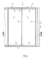
- FIG. 1 to 3 show a side view and cross sections through a plurality of all-glass sliding sashes 1 which are attached to one another and form part of a sliding wall.
- a connecting element 6, 8 is fastened to a wall 3 fixed to the building, the horizontal length of which - in the plane of the sliding wall - can be adjusted so that the number of glass panels provided can separate the available width of the room.
- a horizontal guide rail 30 is fastened to the ceiling, defining the level of the sliding wall, which has a downward-pointing guide gap 32, through which at least two support members 26 fastened to the upper horizontal edge of a glass plate 12 protrude and by means of their rollers 28 on running surfaces 33 Guide rail 30 can be moved horizontally together with the sliding sash.
- the glass plate 12 is provided with peripheral edge 14.
- the two vertical sections 20, 22 of the rim 14 have a form-fitting complementary profile, so that in each case an edge bead of the one vertical section 20 in each case form into a complementary edge groove of the adjacent vertical section 22 of the adjacent sliding sash intervenes conclusively.
- cf. Fig. 3 have edge bead and edge groove in a wedge shape, so that a good, the air passage inhibiting positive connection is realized even with low, horizontally acting closing forces.
- the upper and the lower horizontal sections 16, 18 of the border 14 are glued to the glass plate 12 and / or fastened by fastening elements 17.
- the supporting members 26 are fastened to the upper side of the upper horizontal section 16.
- the upper horizontal section 16 bears elastic, brush-shaped sealing elements 29 which are directed against the running rail 30 and which sufficiently inhibit the air circulation also in the region of the upper horizontal sections 16 of the sliding sash 1.
- FIG. 4 and 5 show a side view and a horizontal section of a second embodiment of the invention, in which the border 14 - Per sliding wing 1 - is only attached to the upper and lower horizontal edge and only to a vertical edge of the glass plate 12, while the other vertical edge of the glass plate 12 is not bordered.
- the upper horizontal section 16 is located on the upper horizontal edge of the glass plate, and the corresponding lower horizontal section 18 of the edge surround 14 is located on the lower horizontal edge.
- the horizontal sections 16, 18 are each by a vertical section 22 on the right (alternatively from the left) vertical edge of the glass plate 12 connected. As can be seen in particular from FIG.
- the vertical section 22 has a vertical groove facing away from the glass plate 12, but in alignment with the glass plate 12, into which the edge of the glass plate of the adjacent sliding sash which is not bordered can be pushed in order to build the sliding sash next to one another in the closed position .
- a bottom seal 40 with a horizontal sealing strip 41 is framed in a gap of the lower horizontal section 18 of the rim 14, which - in the embodiment shown - is fastened by means of two fastening elements 36 fastened to the horizontal section 18 and to the fastening elements 36 parallel pivot levers 38 are arranged which carry the sealing strip 41 at their lower end and are articulated by means of a link guide 37, 39 so as to be displaceable and pivotable.
- the springs 42 are designed as leg springs, which preload the sealing strip in its relieved position.
- the first leg 44 of the leg spring 42 is fastened to the sealing strip 41, the second leg 46 is offset horizontally and vertically upwards on the fastening element 36 of the rim 18.
- the movement of the leg springs 42 is controlled by a stationary stop 48 when the sealing strip 41 is moved so that the sealing strip 41 passes through a dead center during its movement from the unloaded position into the loaded, extended ground position.
- the upper and lower horizontal sections 16, 18 of the rim 14 end at a predetermined distance from the vertical edge 14a of the glass plate 14.
- end pieces 50 are attached, the horizontal length of which corresponds to the width of the vertical sections 20, 22, and which run in a wedge shape to a predetermined edge dimension D towards the outer edge 54 and have a vertical, wedge-shaped shoulder 56 or a corresponding key groove 58 on the outer edge 54.
- the profile of the vertical sections 20, 22 is overall slimmer than that of the horizontal sections 16, 18, it also has the edge dimension D on the outer edge 54 and tapers in a wedge shape toward the glass plate 14.
- the vertical sections 20, 22 set the joint as small as possible End pieces 50.
- the vertical sections 20, 22 also have a wedge-shaped groove 56 or a corresponding wedge-shaped recess 58 on the outer edge 54 in order to allow two adjoining sliding sashes to engage sufficiently tightly on their vertical edge so that the tree zones separated by the sliding sashes are adequately separated.
- the profile of the horizontal sections 16, 18 and possibly the end pieces 50 can be chamfered towards the glass plates.
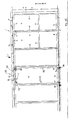
- FIG. 11 shows a representation corresponding to FIG. 1 of a sliding wall or partition wall composed of several door leaves 1.
- the dividing wall also contains a sliding door leaf 1 a, which also has a glass plate 12, the support members 26 being anchored in the upper rim 16.
- the glass plate 12 is rotatably connected to the upper rim 16 only by means of a first vertical pin 66.
- a second pin 68 is vertically displaceably mounted in the lower rim 18 of the door leaf, which can be pushed into a corresponding floor recess by the user by means of a pivoting lever and thereby defines the vertical axis of rotation 70 of the door leaf.
- a pivot hook 52 is pivoted about the horizontal axis at a distance from the axis of rotation 70 on the upper edge mount 16.
- a corresponding counter pin 54 is fastened in the glass plate 12 and, when actuated, can be gripped by the swivel hook 52 and locked with the upper rim 16.
- a lock 51 is inserted with a in a bottom opening available locking pin.
- the sliding leaf 1 adjacent to the door leaf 1 a can also be anchored in the housing base by means of vertically extendable plug pins 58.
- downward-facing approaches can be formed on the swiveling floor seals of the adjacent sliding sashes, which engage in corresponding recesses in the floor when the floor seal is extended and thereby also bring about a positive anchoring of the fixed sliding sashes.
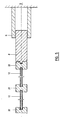
- FIG. 12 shows a special floor anchoring of the sliding door leaf, which can be used as an alternative to the manual anchoring shown in FIG. 11.
- a second pin 68 in the lower rim 18, which is mounted vertically displaceably in a sleeve 71 and can be moved vertically out of the lower rim 18 into a bottom groove 78.
- a spring-loaded toggle lever 72 is provided, one end of which is articulated on the door leaf 1a or the wing-fixed sleeve 71, and the other leg of which is articulated on the second pin 68, and on the knee joint of which an actuating member 74 is moved vertically outward from the casement frame against the floor seal of the adjacent sliding wing 1 is directed.
- the actuating member 74 of the door leaf 1a is adjacent - approximately in the extension of the lower edge of the bottom seal 41 - a horizontal bottom flap 80 directed against the door leaf 1a Elongated hole 82 arranged.
- the actuating member 74 comes into contact with the pivotable bottom seal 41, which is thereby pivoted under the sliding leaf 1.
- the door leaves 1a and sliding leaf 1 come closer together, so that at the same time as the pivoting movement the bottom flap 80 runs under the door leaf 1a until the hole 82 is aligned with the second pin 68 and the bottom groove 78.
- the pin 68 is finally pushed through the slot 82 into the bottom groove 78.
- the elongated hole 82 of the base plate 80 is shorter than the base groove 78 in order to produce an exact relative position of the sliding leaf 1 and the door leaf 1a.
- the sliding sash 1 is also positively secured in position. In this way, when the door leaf 1a and the adjacent sliding leaf 1 are fixed, the floor anchoring of the door leaf 1a is automatically carried out. Manual setting of the pin 68 is no longer necessary.
- the glass plate 12 of the door leaf 1a is preferably provided with the border 14 on at least one vertical edge.
- the corresponding vertical section 20 of the border 14 has a form-fitting complementary profile with the adjacent profile 22 of the adjacent sliding sash.
Abstract
Description
- Die Erfindung betrifft einen Ganzglas-Schiebeflügel für eine Schiebewand, mit mindestens einem an der oberen Horizontalkante einer Glasplatte befestigten Tragorgan, an dem/denen der Schiebeflügel in einer horizontalen Führungsschiene verschiebbar abgehängt ist.
- Derartige Ganzglas-Schiebeflügel werden von verschiedenen Herstellern angeboten, so z.B. von der Firma VEGLA Vereinigte Glaswerke GmbH, D - 5100 Aachen, gemäß dem Prospekt "Horizontal-Schiebewand" vom Juni 1985. Diese bekannten Ganzglas-Schiebeflügel sind Teil einer Schiebewand und werden an Tragorganen geführt, die an der oberen und an der unteren Horizontalkante einer Ganzglasplatte befestigt sind und in einer entsprechenden horizontalen Decken-Führungsschiene und einer unteren Boden-Führungsschiene verschiebbar gelagert sind. Derartige Schiebewände aus Ganzglas-Schiebeflügel dienen zur Aufteilung von Festhallen, Restaurants und Läden. Sie sollen bei offener Sicht eine Raumtrennung, eine Schalldämmung etc. ermöglichen. Nachteilig ist dabei, daß diese bekannten Ganzglas-Schiebeflügel nur mit einem Vertikalspalt aneinander ansetzbar sind, so daß - zusammen mit der Transparenz der Glasscheiben - die Schiebewand nicht den Eindruck einer geschlossenen, insbesondere rauchdichten Abtrennung erzeugt, und zur tatsächlichen raumluftdichten Abtrennung unterschiedlicher Raumzonen, wie z.B. von Raucher- und Nichtraucherzonen auch nicht geeignet ist.
- Aufgabe ist es demgegenüber, einen Ganzglas-Schiebeflügel der eingangs genannten Art derart weiterzubilden, daß eine aus diesen Schiebeflügeln aufgebaute Schiebewand eine verbesserte, dichtere Trennung benachbarter Raumzonen in optisch ansprechender Weise ermöglicht.
- Diese Aufgabe wird bei den Ganzglas-Schiebeflügeln der eingangs genannten Art erfindungsgemäß dadurch gelöst, daß die Glasplatte an ihrer oberen und unteren Horizontalkante und mindestens an einer Vertikalkante mit einer Randeinfassung versehen ist, daß die Vertikalabschnitte der Randeinfassung ein formschlüssig komplementäres Profil mit dem angrenzenden Profil des benachbarten Schiebeflügels besitzen, und daß in dem unteren Horizontalabschnitt der Randeinfassung eine Bodendichtung angeordnet ist, die sich beim Auftreffen auf einen vorausgehenden Schiebeflügel etc. auf den Boden absenkt und beim Abziehen des Schiebeflügels anhebt.
- Die Vorteile der Erfindung liegen insbesondere darin, daß jeder Schiebeflügel mindestens an einer Vertikalkante eine Randeinfassung besitzt, deren Profil komplementär zu dem angrenzenden Profil des benachbarten Schiebeflügels ist, wodurch eine dichtere Trennung der voneinander abgetrennten Raumzonen erreicht wird. Ist jeweils nur die eine Vertikalkante der Schiebeflügel-Glasscheiben mit einer Randeinfassung versehen, so ist diese Randeinfassung so profiliert, daß die jeweils nicht eingefaßte Glasscheibe in einen entsprechenden Spalt des angrenzenden Randprofils des Nachbarflügels eingreift. Bei geschlossener Schiebewand befindet sich dann zwischen den Schiebeflügeln jeweils nur ein Vertikalholm, dessen horizontale Breite schmal gehalten werden kann, so daß zwischen den benachbarten Glasplatten nur eine sehr schmale, optisch ansprechende Randeinfassung den Zusammenhang der Glasplatten unterbricht.
- Alternativ läßt sich dagegen die Glasplatte jedes Schiebeflügels mit einer umlaufenden Randeinfassung versehen. Bei dieser Ausführungsform sind dann die beiden Vertikalabschnitte der Randeinfassung mit einem formschlüssig komplementären Profil versehen, um ein Ineinandergreifen benachbarter Vertikalabschnitte der benachbarten Schiebeflügel einfach und gut schließend zu ermöglichen. Zwischen jeweils zwei Schiebeflügeln befinden sich dann zwei komplementär profilierte Vertikalholme, die den optischen Zusammenhang aufgrund ihrer größeren Gesamtbreite stärker unterbrechen. Außerdem ist in dem unteren Horizontalabschnitt der Randeinfassung eine Bodendichtung vorgesehen, die in der Endlage des Ganzglas-Schiebeflügels ausfahrbar ist, den Schiebflügel in seiner Endposition festsetzt und gegen den Boden abdichtet. Besonders bevorzugt besitzt auch der obere Horizontalabschnitt der Randeinfassung ein gegen die Laufschiene oder die Decke gerichtetes elastisches oder bürstenförmiges Dichtelement. Bei dieser Ausführungsform ist eine gute Abdichtung der gesamten Schiebewand gegen Luftzug, sowie eine gute Abtrennung der Zonen gegen das Eindringen der Raumluft oder Umgebungsluft der benachbarten Zone gewährleistet. Es stellt dabei einen besonderen Vorteil der Erfindung dar, daß die umlaufende Randeinfassung das formschlüssige Ineinandergreifen der einzelnen Schiebeflügel und die vorhandene Boden- und Deckenabdichtung, also die Geschlossenheit der Schiebewand optisch besonders betont, so daß der sich in einer Raumzone aufhaltende Kunde oder Benutzer auch den Eindruck einer geschlossenen Raumabtrennung erhält, ohne daß die Leichtigkeit und Eleganz der Glaswand eine Einbuße erfährt.
- Besonders bevorzugt enthält die Bodendichtung eine horizontale Dichtleiste, die über mindestens zwei beabstandete parallele Schwenkhebel in einem Spalt der Randeinfassung mittels einer Kulissenführung verschiebbar und schwenkbar gelagert ist. Die Konstruktion dieser Bodendichtung ist so ausgebildet, daß diese beim Anlaufen gegen einen benachbarten, festgesetzten Schiebeflügel durch die dabei wirkenden Kräfte gegen den Boden abwärts geschwenkt wird und beim Zurückfahren des Schiebeflügels in seine Parkstellung wieder automatisch gelöst wird.
- Besonders bevorzugt enthält dieser Ganzglas-Schiebeflügel in vorgegebener Höhe einen horizontalen Brüstungsriegel, der an den beiden Vertikalabschnitten der Randeinfassung befestigt werden kann. Dieser Brüstungsriegel macht dem Benutzer oder Passanten das Vorhandensein der Schiebewand optisch deutlich, er läßt sich außerdem als Griff zum Verfahren der Schiebeflügel einsetzen.
- Bevorzugt sind in die Vertikalabschnitte der Randeinfassung Magnetleisten integriert, wobei die Magnetleisten einander benachbarter Vertikalkanten jeweils unterschiedliche Polarität aufweisen, um das formschlüssige Ineinanderführen dieser Vertikalabschnitte beim Aneinandersetzen der Schiebeflügel auch durch die magnetischen Anziehungskräfte der Magnetleisten zu unterstützen.
- Während die Horizontalabschnitte zur Aufnahme von Konstruktionsteilen, insbesondere der Bewegungsmechanik und die Dichtleiste relativ breit sein muß, können die Vertikalabschnitte zur Erfüllung ihrer Dichtfunktion aus einem relativ dünnen Profil bestehen. Um einen konstruktiv einfachen, optisch jedoch ansprechenden Übergang von den Horizontalabschnitten auf die Vertikalabschnitte zu verwirklichen, wird erfindungsgemäß vorgesehen, die Horizontalabschnitte deren Einfassung einen vorgegebenen Abstand vor der Vertikalkante der Glasplatte enden zu lassen und an den Enden der Horizontalabschnitte Endstücke anzusetzen, die besonders bevorzugt keilförmig auf ein vorgegebenes Randmaß zur Außenkante hin sich verjüngen. Die Endstücke besitzen in vorteilhafter Weise die horizontale Länge, welche gleich der entsprechenden horizontalen Breite der Vertikalabschnitte ist, um einen fließenden Übergang zu den Vertikalabschnitten verwirklichen zu können.
- Besonders bevorzugt verjüngt sich das Profil der Vertikalabschnitte von der Außenkante der Randeinfassung keilförmig zur Glasplatte hin, das Randmaß an der vertikalen Außenkante der Randeinfassung ist bei den angesetzten Endstücken und den sich anschließenden Vertikalabschnitten bevorzugt gleich groß. Alternativ ist es auch möglich, die Vertikalabschnitte über die gesamte vertikale Höhe des Schiebeflügels laufen zu lassen und die Horizontalabschnitte entsprechend zu verkürzen.
- Als formschlüssig komplementäres Profil zwischen zwei Vertikalabschnitten zweier einander benachbarter Schiebeflügel enthält bevorzugt der eine Vertikalabschnitt 20 eine vertikale Nut 56 an der Außenkante 44, der gegenüberliegende vertikale Abschnitt 22 enthält eine entsprechende Ausnehmung 58.
- Gemäß einer besonders bevorzugten Ausführungsform der Erfindung kann in einer aus mehreren Schiebeflügeln zusammengesetzten Trennwand auch ein Türflügel vorgesehen werden, bei dem die Glasplatte von der oberen Randeinfassung getrennt ist und die Tragorgane an der oberen Randeinfassung befestigt sind. Ein derartiger Türflügel ist mittels eines ersten Zapfens an der oberen Randeinfassung drehbar angeschlagen. Vorgesehen ist in einer vertikalen Drehachse fluchtend ein zweiter Zapfen, der von der unteren Randeinfassung vertikal nach unten in eine Bodennut ausgefahren werden kann und zusammen mit dem ersten Zapfen dann die Drehachse des Türflügels definiert.
- Gemäß einer besonders bevorzugten Ausführungsform der Erfindung ist der zweite Zapfen in der unteren Randeinfassung mit einem zur Vertikalkante des Türflügels herausgeführten Betätigungsorgan gekoppelt, welches beim Anlaufen gegen einen benachbarten Schiebeflügel betätigt wird und den zweiten Zapfen dabei in eine darunter befindliche gebäudefeste Bodennut ausfährt. Vorteilhaft ist es bei dieser Ausführungsform der Erfindung, daß der untere Zapfen des Türflügels, welcher zur Festlegung der Drehachse am Boden o.dgl. verankert werden muß, beim Aufbau der Wand automatisch ausgefahren und gesetzt wird. Die manuelle Verankerung des Zapfens im Boden kann daher entfallen.
- Gemäß einer besonders bevorzugten Ausführungsform der Erfindung ist der zweite Zapfen des Türflügels in einer vertikalen Buchse verschiebbar gelagert. Das Betätigungsorgan ist an dem Kniegelenk eines einseitig am Türflügel angeschlagenen, federbelasteten Kniehebels befestigt. Der freie Schenkel des Kniehebels ist an dem zweiten Zapfen angelenkt, so daß bei einer Vertikalbewegung des Betätigungsorgans der zweite Zapfen über den federbelasteten Kniehebel vertikal verschiebbar ist.
- Besonders bevorzugt ist an der absenkbaren Bodendichtung eines angrenzenden Schiebeflügels dem Betätigungsorgan des Türflügels benachbart - etwa in Verlängerung der Unterkante der Bodendichtung - eine gegen den Türflügel gerichtete horizontale Bodenlasche mit einem Langloch vorgesehen. Bei Annäherung des Türflügels an den benachbarten Schiebeflügel kommt zuerst das Betätigungsorgan in Berührungskontakt mit der Stirnseite der Bodendichtung, die vom Betätigungsorgan in eine abwärts- und in Schubrichtung verlaufende Schwenkbewegung gedrückt wird, während der Türflügel näher an den Schiebeflügel herangeschoben wird. Dabei bewegt sich die Bodenlasche der Bodendichtung zwischen die Unterkante des Türflügels und die Bodennut. Anschließend wird bei weiterer Annäherung des Türflügels an den Schiebeflügel der zweite Zapfen vertikal durch das Langloch der Bodenlasche in die Bodennut abgesenkt und arretiert.
- Besonders bevorzugt ist das Langloch der Bodenlasche kürzer als die darunter befindliche Bodennut. Auf der Unterseite der Bodenlasche ist um das Langloch herum ein Wulst angeformt, der beim Setzen der Flügel in die Bodennut hineingepreßt wird, wobei dann das Langloch die genaue Position für den zweiten Zapfen festlegt.
- Besonders bevorzugt ist an dem Türflügel in vorgegebenem Abstand von der Drehachse ein Schwenkhaken in der oberen Randeinfassung um eine horizontale Achse schwenkbar befestigt. Vorgesehen ist ferner in der Glasplatte ein entsprechend angebrachter horizontaler Gegenzapfen, der bei Betätigung des Schwenkhakens vom Schwenkhaken umfaßt bzw. freigegeben wird. Durch diesen Schwenkhaken erfolgt die Befestigung der Glasplatte in der Wandebene, falls die Tür des Schiebe-Türflügels nicht als Schwenktür benutzt werden soll.
- Um eine festere Verankerung des aus Tragorganen und oberer Randeinfassung bestehenden Laufwerks des Schiebe-Türflügels zu verwirklichen, ist bevorzugt in der oberen Randeinfassung ein vertikal in den Spalt der Tragschiene ausfahrbarer Keil vorgesehen.
- Um die einzelnen Schiebeflügel mittels der absenkbaren, gegen den Boden preßbaren Bodendichtung auch formschlüssig am Boden zu verankern, können vorteilhafterweise an der Bodendichtung abwärtsgerichtete Ansätze angeformt sein, die beim Ausfahren der Bodendichtung in entsprechende bodenfeste Nuten oder Ausnehmungen greifen.
- Vorteilhafte Weiterbildungen der Erfindung sind durch die Merkmale der Unteransprüche gekennzeichnet.
- Im folgenden werden zwei Ausführungsbeispiele der Erfindung anhand der Zeichnung näher erläutert.
- Es zeigen:
- Fig. 1 eine Seitenansicht mehrerer benachbarter Ganzglas-Schiebeflügel mit umlaufender Randeinfassung;
- Fig. 2 einen vertikalen Querschnitt längs der Linie II-II der Fig. 1;
- Fig. 3 einen horizontalen Querschnitt längs der Linie III-III der Fig. 1;
- Fig. 4 eine der Fig. 1 entsprechende Darstellung einer zweiten Ausführungsform der Erfindung;
- Fig. 5 eine der Fig. 3 entsprechende Darstellung der zweiten Ausführungsform;
- Fig. 6 eine Seitenansicht der Bodenabdichtung bei entfernter Seitenabddeckung der dortigen Randeinfassung;
- Fig. 7 die Einzelheit Y der Fig. 6 in vergrößerter Darstellung;
- Fig. 8 einen horizontalen Querschnitt durch die Horizontalabschnitte zweier benachbarter Schiebeflügel;
- Fig. 9 einen horizontalen Querschnitt durch die Vertikalabschnitte zweier benachbarter Schiebeflügel;
- Fig.10 die unteren horizontalen Abschnitte zweier benachbarter Schiebeflügel, von oben gesehen;
- Fig. 11 eine der Fig. 1 entsprechende Darstellung einer Trennwand mit einem Schiebe-Türflügel; und
- Fig. 12 eine Einzelheit eines Schiebe-Türflügels.
- Die Fig. 1 bis 3 zeigen eine Seitenansicht und Querschnitte durch mehrere aneinander angesetzte Ganzglas-Schiebeflügel 1, die Teil einer Schiebewand bilden. An einer gebäudefesten Wand 3 ist ein Anschlußelement 6, 8 befestigt, dessen horizontale Länge - in der Ebene der Schiebewand - so einstellbar ist, daß die vorgesehene Anzahl an Glasflügeln die zur Verfü- gung stehende lichte Weite des Raumes abtrennen kann. An der Decke ist, die Ebene der Schiebewand festlegend, eine horizontale Führungsschiene 30 befestigt, die einen nach unten weisenden Führungsspalt 32 besitzt, durch den mindestens zwei an der oberen Horizontalkante einer Glasplatte 12 befestigte Tragorgane 26 hindurchragen und mittels ihrer Laufrollen 28 auf Laufflächen 33 der Führungsschiene 30 zusammen mit dem Schiebeflügel horizontal verfahrbar sind.
- Die Glasplatte 12 ist mit umlaufender Randeinfassung 14 versehen. Die beiden Vertikalabschnitte 20, 22 der Randeinfassung 14 besitzen ein formschlüssig komplementäres Profil, so daß jeweils ein Randwulst des einen Vertikalabschnitts 20 jeweils in eine komplementäre Randnut des benachbarten Vertikalabschnitts 22 des benachbarten Schiebeflügels form schlüssig eingreift. In der dargestellten Ausführungsform, vgl. Fig. 3, weisen Randwulst und Randnut keilförmig ineinander, so daß auch bei geringen, horizontal wirkenden Schließkräften eine gute, den Luftdurchlaß hemmende Formschluß-Verbindung verwirklicht wird.
- Wie insbesondere der Fig. 2 entnehmbar ist, sind der obere und der untere Horizontalabschnitt 16, 18 der Randeinfassung 14 mit der Glasplatte 12 verklebt und/oder durch Befestigungselemente 17 befestigt. An der Oberseite des oberen Horizontalabschnitts 16 sind die Tragorgane 26 befestigt. Außerdem trägt der obere Horizontalabschnitt 16 gegen die Laufschiene 30 gerichtete elastische, bürstenförmige Dichtelemente 29, welche die Luftzirkulation auch im Bereich der oberen Horizontalabschnitte 16 der Schiebeflügel 1 ausreichend hemmen.
- Die Schiebeflügel 1 besitzen, vgl. Fig. 1, in vorgegebener Höhe horizontale Brüstungsriegel 24, die an den beiden Vertikalabschnitten 20, 22 der Randeinfassung 14 befestigt sind und die Glasplatten 2 für die Benutzer optisch deutlich hervortreten lassen und außerdem als Griff zum Bewegen der Schiebeflügel 1 dienen.
- Die Fig. 4 und 5 zeigen eine Seitenansicht und einen Horizontalschnitt einer zweiten Ausführungsform der Erfindung, bei der die Randeinfassung 14 - Pro Schiebeflügel 1 - jeweils nur an der oberen und der unteren Horizontalkante und lediglich an einer Vertikalkante der Glasplatte 12 angebracht ist, während die andere Vertikalkante der Glasplatte 12 uneingefaßt ist. An der oberen Horizontalkante der Glasplatte befindet sich der obere Horizontalabschnitt 16, an der unteren Horizontalkante der entsprechende untere Horizontalabschnitt 18 der Randeinfassung 14. Die Horizontalabschnitte 16, 18 sind durch einen Vertikalabschnitt 22 an jeweils der rechten (alternativ von der linken) Vertikalkante der Glasplatte 12 verbunden. Wie insbesondere der Fig. 4 entnehmbar ist, besitzt der Vertikalabschnitt 22 von der Glasplatte 12 abgewandt, jedoch mit der Glasplatte 12 fluchtend eine Vertikalnut, in welche die nicht eingefaßte Kante der Glasplatte des benachbarten Schiebeflügels hineingeschoben werden kann, um die Schiebeflügel nebeneinander in Schließposition aufzubauen. Gemäß den Fig. 6 und 7 ist in einem Spalt des unteren Horizontalabschnitts 18 der Randeinfassung 14 eine Bodendichtung 40 mit einer horizontalen Dichtleiste 41 eingefaßt, die - in der dargestellten Ausführungsform - mittels zweier am Horizontalabschnitt 18 befestigter Befestigungselemente 36 befestigt ist und an den Befestigungselementen 36 sind parallele Schwenkhebel 38 angeordnet, welche an ihrem unteren Ende die Dichtleiste 41 tragen und mittels einer Kulissenführung 37, 39 verschiebbar und verschwenkbar angelenkt sind. In ihrer entlasteten Stellung ragt die Dichtleiste 41 über eine Vertikalkante des Schiebeflügels 1 hinaus und wird beim Auftreffen auf einen festen Schiebeflügel etc. horizontal gegen die Wirkung von Federn 42 unter den Schiebeflügel 1 geschoben und dabei gegen den Boden 2 abwärts geschwenkt und angepreßt. Die Federn 42 sind als Schenkelfedern ausgebildet, welche die Dichtleiste in ihrer entlasteten Stellung vorspannen. Der erste Schenkel 44 der Schenkelfeder 42 ist an der Dichtleiste 41, der zweite Schenkel 46 horizontal und vertikal nach oben versetzt an dem Befestigungselement 36 der Randeinfassung 18 befestigt. Die Bewegung der Schenkelfedern 42 ist beim Bewegen der Dichtleiste 41 durch einen stationären Anschlag 48 so gesteuert, daß die Dichtleiste 41 bei ihrer Bewegung aus der entlasteten Stellung in die belastete, ausgefahrene Bodenstellung einen Todpunkt durchläuft.
- Die Fig. 8, 9 und 10 zeigen horizontale Querschnitte durch die oberen Horizontalabschnitte, die Vertikalabschnitte und eine Draufsicht auf die unteren Horizontalabschnitte zweier benachbarter Schiebeflügel. Die oberen und die unteren Horizontalabschnitte 16, 18 der Randeinfassung 14 enden in vorgegebenem Abstand vor der Vertikalkante 14a der Glasplatte 14. An den Enden der Horizontalabhschnitte 16, 18 sind Endstücke 50 angesetzt, deren horizontale Länge der Breite der Vertikalabschnitte 20, 22 entspricht, und welche keilförmig auf ein vorgegebenes Randmaß D zur Außenkante 54 hin auslaufen und an der Außenkante 54 einen vertikallaufenden, keilförmigen Ansatz 56 bzw. eine entsprechende Keilnut 58 aufweisen. Das Profil der Vertikalabschnitte 20, 22 ist insgesamt schlanker als das der Horizontalabschnitte 16, 18, es besitzt an der Außenkante 54 ebenfalls das Randmaß D und verjüngt sich keilförmig zur Glasplatte 14 hin. Die Vertikalabschnitte 20, 22 setzen mit möglichst geringer Fuge an den Endstücken 50 an. Die Vertikalabschnitte 20, 22 besitzen an der Außenkante 54 ebenfalls eine keilförmige Nut 56 bzw. eine entsprechende keilförmige Ausnehmung 58, um zwei aneinander angrenzende Schiebeflügel an ihrer Vertikalkante ausreichend dicht ineinandergreifen zu lassen, damit die durch die Schiebeflügel abgetrennten Baumzonen ausreichend abgetrennt werden. Das Profil der Horizontalabschnitte 16, 18 und ggf. der Endstücke 50 kann zu den Glasplatten hin angefast werden.
- Fig. 11 zeigt eine der Fig. 1 entsprechende Darstellung einer aus mehreren Türflügeln 1 zusammengesetzten Schiebewand oder Trennwand. Die Trennwand enthält neben mehreren, in den Fig. 1 bis 10 dargestellten Schiebeflügeln 1 auch einen Schiebe-Türflügel 1a, der ebenfalls eine Glasplatte 12 aufweist, wobei die Tragorgane 26 in der oberen Randeinfassung 16 verankert sind. Die Glasplatte 12 ist an der oberen Randeinfassung 16 nur mittels eines ersten vertikalen Zapfens 66 drehbar verbunden. Vertikal fluchtend ist in der unteren Randeinfassung 18 des Türflügels ein zweiter Zapfen 68 vertikal verschiebbar gelagert, der mittels eines Schwenkhebels vom Benutzer in eine entsprechende Bodenmulde geschoben werden kann und dadurch die vertikale Drehachse 70 des Türflügels festlegt. An der oberen Randeinfassung 16 ist von der Drehachse 70 beabstandet ein Schwenkhaken 52 um eine horizontale Achse schwenkbar angelenkt. In der Glasplatte 12 ist ein entsprechender Gegenzapfen 54 befestigt, der bei Betätigung vom Schwenkhaken 52 untergriffen und mit der oberen Randeinfassung 16 verriegelt werden kann. In der unteren Randeinfassung 18 ist noch ein Schloß 51 mit einem in eine Bodenöffnung einsteck baren Schließzapfen vorgesehen. Um ein ausreichend stabiles Gegenlager für den Türflügel 1a zu bilden, können die dem Türflügel 1a benachbarten Schiebeflügel 1 noch mittels vertikal ausfahrbarer Steckzapfen 58 in dem Gehäuseboden verankert werden. Außerdem können an den abschwenkbaren Bodendichtungen der benachbarten Schiebeflügel 1 abwärtsgerichtete Ansätze angeformt sein, die beim Ausfahren der Bodendichtung in entsprechende Ausnehmungen des Bodens greifen und dadurch auch eine formschlüssige Verankerung der festgesetzten Schiebeflügel bewirken.
- In Fig. 12 ist eine spezielle Bodenverankerung des Schiebe-Türflügels dargestellt, die alternativ zu der in Fig.11 dargestellten manuellen Verankerung eingesetzt werden kann. Vertikal fluchtend zum ersten Zapfen 66 befindet sich in der unteren Randeinfassung 18 ein zweiter Zapfen 68, der in einer Hülse 71 vertikal verschiebbar gelagert ist und vertikal aus der unteren Randeinfassung 18 in eine Bodennut 78 verfahren werden kann. Vorgesehen ist ein federbelasteter Kniehebel 72, dessen eines Ende am Türflügel 1a bzw. der flügelfesten Hülse 71 angelenkt, und dessen anderer Schenkel an dem zweiten Zapfen 68 angelenkt ist, und an dessen Kniegelenk ein Betätigungsorgan 74 vertikal aus dem Flügelrahmen nach außen gegen die Bodendichtung des benachbarten Schiebeflügels 1 gerichtet ist.
- An der absenkbaren Bodendichtung 41 des angrenzenden Schiebeflügels 1 ist dem Betätigungsorgan 74 des Türflügels 1a benachbart - etwa in Verlängerung der Unterkante der Bodendichtung 41 - eine gegen den Türflügel 1a gerichtete horizontale Bodenlasche 80 mit einem Langloch 82 angeordnet. Auf der Unterseite der Bodenlasche 80 ist - um das Langloch 82 herum - ein Wulst 84 angeordnet, der in die Bodennut 78 paßt.
- Bei Annäherung des Türflügels 1a an den benachbarten Schiebeflügel 1 kommt das Betätigungsorgan 74 in Berührungskontakt mit der abschwenkbaren Bodendichtung 41, die dadurch unter den Schiebeflügel 1 geschwenkt wird. Bei dieser Schwenkbewegung nähern sich die Türflügel 1a und Schiebeflügel 1 stärker an, so daß gleichzeitig mit der Schwenkbewegung die Bodenlasche 80 unter den Türflügel 1a läuft, bis das Loch 82 mit dem zweiten Zapfen 68 und der Bodennut 78 fluchtet. Anschließend wird bei weiterer Annäherung des Türflügels 1a und des Schiebeflügels 1 schließlich der Zapfen 68 durch das Langloch 82 in die Bodennut 78 geschoben. Das Langloch 82 der Bodenlasche 80 ist kürzer als die Bodennut 78, um eine genaue Relativlage von Schiebeflügel 1 und Türflügel 1a herzustellen. Durch das Absenken des Wulstes 84 in die Bodennut 78 wird auch der Schiebeflügel 1 formschlüssig lagegesichert. Auf diese Weise wird beim Festsetzen des Türflügels 1a und dem angrenzenden Schiebeflügel 1 automatisch die Bodenverankerung des Türflügels 1a durchgeführt. Das manuelle Setzen des Zapfens 68 ist nicht mehr erforderlich.
- Die Glasplatte 12 des Türflügels 1a ist bevorzugt an mindestens einer Vertikalkante mit der Randeinfassung 14 versehen. Der entsprechende Vertikalabschnitt 20 der Randeinfassung 14 besitzt ein formschlüssig komplementäres Profil mit dem angrenzenden Profil 22 des benachbarten Schiebeflügels.
Claims (21)
(14) eine Bodendichtung (40) angeordnet ist, die sich beim Auftreffen auf einen vorausgehenden Schiebeflügel etc. auf den Boden absenkt und beim Abziehen des Schiebeflügels (1) anhebt.
dadurch gekennzeichnet, daß die Dichtleiste (41) mittels Schenkelfedern (42) in die entlastete Stellung vorgespannt ist, und daß die Schenkelfedern (42) mit ihrem ersten Schenkel (44) an der Dichtleiste, mit dem zweiten Schenkel (46) horizontal und vertikal nach oben versetzt an einem festen Lagerbock (36) der Randeinfassung (14, 18) befestigt sind, und daß die Bewegung der Schenkelfedern (42) beim Bewegen der Dichtleiste (41) durch einen Anschlag (48) über dem zweiten Schenkel (46) gesteuert ist.
dadurch gekennzeichnet, daß in vorgegebener Höhe ein Brüstungsriegel (24) horizontal angeordnet ist und an beiden Vertikalabschnitten (20, 22) der Randeinfassung (14) befestigt ist.
dadurch gekennzeichnet, daß in die Vertikalabschnitte (20, 22) der Randeinfassung (14) Magnetleisten integriert sind.
dadurch gekennzeichnet, daß der obere Horizontalabschnitt (16) der Randeinfassung (14) gegen die Laufschiene (30) gerichtete elastische oder bürstenförmige Dichtelemente (29) trägt.
dadurch gekennzeichnet, daß die Horizontalabschnitte (16, 18) der Randeinfassung (14) sich horizontal über die Vertikalkante der Glasplatte (12) bis zur Außenkante der Randeinfassung (14) erstrecken und sich keilförmig auf ein vorgegebenes Randmaß zur Außenkante (54) hin verjüngen.
dadurch gekennzeichnet, daß die Horizontalabschnitte (16, 18) der Randeinfassung (14) einen vorgegebenen Abstand vor der Vertikalkante der Glasplatte (12) enden, und daß an den Enden der Horizontalabschnitte (16, 18) Endstücke (50) ansetzen, die teilförmig auf ein vorgegebenes Randmaß (D) zur Außenkante (54) hinauslaufen.
dadurch gekennzeichnet, daß sich das Profil der Vertikalabschnitte (20, 22) der Randeinfassung (14) von der Außenkante (54) der Randeinfassung teilförmig zur Glasplatte (14) hin verjüngt.
dadurch gekennzeichnet, daß das Randmaß (D) an der vertikalen Außenkante (54) der Randeinfassung (14) über die gesamte Länge der Außenkante konstant ist.
dadurch gekennzeichnet, daß das Profil der Horizontalabschnitte (16, 18) und ggf. der Endstücke (50) zu der Glasplatte (14) hin angefast ist.
dadurch gekennzeichnet, daß der zweite Zapfen (68) mit einem zur Vertikalkante herausgeführten Betätigungsorgan (74) gekoppelt ist, welches beim Anlaufen gegen einen benachbarten Schiebeflügel den zweiten Zapfen (68) in eine darunter befindliche gebäudefeste Bodennut (78) ausfährt.
dadurch gekennzeichnet, daß das Langloch (82) der Bodenlasche (80) kürzer ist als die Bodennut (78).
dadurch gekennzeichnet, daß an der Unterseite der Bodenlasche (80) um das Langloch (82) herum ein in die Bodennut (78) passender Wulst (84) angeordnet ist.
dadurch gekennzeichnet, daß in der oberen Randeinfassung (16) von der Drehachse (70) beabstandet ein Schwenkhaken (52) um eine horizontale Achse schwenkbar lagert und einen in der Glasplatte (12) entsprechend angebrachten horizontalen Gegenzapfen (54) festhält oder freigibt.
dadurch gekennzeichnet, daß in der oberen Randeinfassung (16) ein vertikal in den Spalt der Tragschiene ausfahrender Keil vorgesehen ist.
dadurch gekennzeichnet, daß an der absenkbaren Bodendichtung (41) einzelner Schiebeflügel (1, 1a) mindestens ein abwärtsgerichteter Ansatz angeformt ist, der beim Ausfahren der Bodendichtung (41) in eine entsprechende bodenfeste Längsnut greift.
dadurch gekennzeichnet, daß die Randeinfassung (14) an mindestens einer Vertikalkante der Glasplatte (12) fortgesetzt ist, daß die Vertikalabschnitte (20, 22) der Randeinfassung (14) ein formschlüssig komplementäres Profil mit dem angrenzenden Profil des benachbarten Schiebeflügels besitzen.
Priority Applications (1)
| Application Number | Priority Date | Filing Date | Title |
|---|---|---|---|
| AT89114507T ATE90992T1 (de) | 1988-08-12 | 1989-08-05 | Ganzglas-schiebefluegel fuer eine schiebewand. |
Applications Claiming Priority (2)
| Application Number | Priority Date | Filing Date | Title |
|---|---|---|---|
| DE8810254U DE8810254U1 (de) | 1988-08-12 | 1988-08-12 | |
| DE8810254U | 1988-08-12 |
Publications (3)
| Publication Number | Publication Date |
|---|---|
| EP0354505A2 true EP0354505A2 (de) | 1990-02-14 |
| EP0354505A3 EP0354505A3 (de) | 1991-08-28 |
| EP0354505B1 EP0354505B1 (de) | 1993-06-23 |
Family
ID=6826854
Family Applications (1)
| Application Number | Title | Priority Date | Filing Date |
|---|---|---|---|
| EP89114507A Expired - Lifetime EP0354505B1 (de) | 1988-08-12 | 1989-08-05 | Ganzglas-Schiebeflügel für eine Schiebewand |
Country Status (4)
| Country | Link |
|---|---|
| EP (1) | EP0354505B1 (de) |
| AT (1) | ATE90992T1 (de) |
| DE (2) | DE8810254U1 (de) |
| ES (1) | ES2043984T3 (de) |
Cited By (11)
| Publication number | Priority date | Publication date | Assignee | Title |
|---|---|---|---|---|
| DE9214601U1 (de) * | 1992-10-28 | 1993-01-28 | Abopart Viol Und Partner Gmbh & Co Kg, 2903 Bad Zwischenahn, De | |
| EP0797720A1 (de) * | 1995-10-17 | 1997-10-01 | DORMA GmbH + Co. KG | Ortsveränderliche wand |
| DE19634391A1 (de) * | 1996-08-26 | 1998-03-12 | Dorma Gmbh & Co Kg | Bodenverankerung für Flügel einer ortsveränderbaren Schiebeflügelwand aus Isolierglas |
| EP1070822A2 (de) * | 1999-07-19 | 2001-01-24 | DORMA GmbH + Co. KG | Ortsveränderbare Wand |
| EP1719870A2 (de) | 2005-05-02 | 2006-11-08 | Planet GDZ AG | Türe mit einer Türdichtung |
| EP1748142A2 (de) | 2005-07-30 | 2007-01-31 | Firma F. Athmer | Dichtungsanordnung für eine Schiebetür |
| DE102007030083A1 (de) | 2007-06-28 | 2009-01-02 | Geze Gmbh | Trennwandanordnung |
| WO2009095177A2 (de) * | 2008-01-31 | 2009-08-06 | Dorma Gmbh + Co. Kg | Vorrichtung zur verbindung von verschiebbaren wandelementen |
| DE102010060276A1 (de) * | 2010-10-29 | 2012-05-03 | Dorma Gmbh & Co Kg | Mobile Trennwand |
| EP3130735A1 (de) * | 2015-08-13 | 2017-02-15 | GU Automatic GmbH | Automatische schiebetür mit einer antriebseinheit und verfahrbaren türflügeln |
| CN109267909A (zh) * | 2018-11-28 | 2019-01-25 | 中国建筑标准设计研究院有限公司 | 滑轨式水平封堵钢结构防护密闭门及其施工方法 |
Families Citing this family (6)
| Publication number | Priority date | Publication date | Assignee | Title |
|---|---|---|---|---|
| DE19634390C2 (de) * | 1996-08-26 | 2001-01-18 | Dorma Gmbh & Co Kg | Bodenverankerung für Flügel einer ortsveränderbaren Schiebeflügelwand |
| DE202014102418U1 (de) * | 2014-05-23 | 2015-08-28 | Hücking GmbH | Profilschienensystem für den Einbau von Schiebetüren in Hohlwände |
| KR20190002649A (ko) * | 2016-05-04 | 2019-01-08 | 플래닛 지디제트 아게 | 슬라이딩 도어용 실링 장치 |
| US11118395B2 (en) | 2016-05-04 | 2021-09-14 | Assa Abloy (Schweiz) Ag | Sealing device |
| CN106555537B (zh) * | 2016-11-15 | 2018-03-09 | 佛山市广源铝业有限公司 | 推拉窗 |
| AT525589B1 (de) | 2021-11-02 | 2024-04-15 | Schlotterer Sonnenschutz Systeme Gmbh | Schutzvorrichtung für eine Gebäudeöffnung |
Citations (10)
| Publication number | Priority date | Publication date | Assignee | Title |
|---|---|---|---|---|
| US1404364A (en) * | 1919-02-27 | 1922-01-24 | Angell C Gross | Door strip |
| DK52851C (da) * | 1936-05-26 | 1937-03-22 | Frederik Madsen | Flerrammet Vindue, Dør eller Luge. |
| DE1867168U (de) * | 1962-12-04 | 1963-02-14 | Wilhelm Hess | Mehrfluegelige tuer, insbesondere fuer geschaftshaeuser. |
| EP0003468A2 (de) * | 1978-01-26 | 1979-08-08 | AG für Türautomation | Schiebetür mit Vertikaldichtungseinrichtung |
| US4322914A (en) * | 1979-11-20 | 1982-04-06 | State Wide Aluminum Of Indiana, Inc. | Slideable closure construction |
| US4395854A (en) * | 1980-12-15 | 1983-08-02 | American Standard Inc. | Universal latch means for drop seal assembly for a moveable wall |
| DE8228269U1 (de) * | 1982-10-08 | 1984-07-12 | W. Semer Kg, 5161 Girbelsrath | Duschabtrennung |
| DE8512435U1 (de) * | 1985-04-26 | 1985-06-13 | Hamacher, Walter, 5100 Aachen | Beschlag für Schiebeflügel |
| US4619074A (en) * | 1985-08-12 | 1986-10-28 | Leung Ignatius Y P | Convertible door system |
| EP0247444A2 (de) * | 1986-05-30 | 1987-12-02 | Walter Hamacher | Schiebetür mit Gehflügel |
Family Cites Families (9)
| Publication number | Priority date | Publication date | Assignee | Title |
|---|---|---|---|---|
| US2916112A (en) * | 1957-03-08 | 1959-12-08 | F C Russell Company | Metal window construction |
| CH362827A (fr) * | 1960-06-29 | 1962-06-30 | Elliott Beresford & Son Limite | Ensemble préfabriqué comprenant au moins un panneau coulissant et un cadre dans lequel ce panneau coulisse |
| DE1659674B2 (de) * | 1966-04-05 | 1975-05-15 | Plastiques P.H. (1972) Inc. - P.H. Plastics (1972) Inc., Lauzon, Quebec (Kanada) | Schiebefenster |
| DE2156175B2 (de) * | 1971-11-12 | 1980-01-10 | Wilh. Frank Gmbh, 7022 Leinfelden- Echterdingen | Dichteinrichtung für Kippflügel, insbesondere Schiebe-Kippflügel von Fenstern, Türen u.dgl |
| US4090265A (en) * | 1975-12-02 | 1978-05-23 | Heinz Georg Baus | Partition wall for wet chambers |
| DE3001215C2 (de) * | 1980-01-15 | 1982-12-16 | Hüppe-Acordial GmbH, 2900 Oldenburg | Wandelement für versetzbare Trennwände |
| DE3237291A1 (de) * | 1982-10-08 | 1984-04-12 | W. Semer Kg, 5161 Girbelsrath | Spaltabdichtung fuer schiebeelemente, insbesondere fuer schiebetueren von duschabtrennungen mit eckeinstieg |
| AT379184B (de) * | 1984-01-17 | 1985-11-25 | Meusburger Walter | Trennwand mit horizontal verschiebbaren scheiben |
| DE8437717U1 (de) * | 1984-12-22 | 1985-06-05 | Reinhold Kittelberger u. Söhne oHG, 7014 Kornwestheim | Beschlag für Schiebetüren und Schiebefenster |
-
1988
- 1988-08-12 DE DE8810254U patent/DE8810254U1/de not_active Expired
-
1989
- 1989-08-05 EP EP89114507A patent/EP0354505B1/de not_active Expired - Lifetime
- 1989-08-05 ES ES89114507T patent/ES2043984T3/es not_active Expired - Lifetime
- 1989-08-05 AT AT89114507T patent/ATE90992T1/de active
- 1989-08-05 DE DE8989114507T patent/DE58904781D1/de not_active Expired - Fee Related
Patent Citations (10)
| Publication number | Priority date | Publication date | Assignee | Title |
|---|---|---|---|---|
| US1404364A (en) * | 1919-02-27 | 1922-01-24 | Angell C Gross | Door strip |
| DK52851C (da) * | 1936-05-26 | 1937-03-22 | Frederik Madsen | Flerrammet Vindue, Dør eller Luge. |
| DE1867168U (de) * | 1962-12-04 | 1963-02-14 | Wilhelm Hess | Mehrfluegelige tuer, insbesondere fuer geschaftshaeuser. |
| EP0003468A2 (de) * | 1978-01-26 | 1979-08-08 | AG für Türautomation | Schiebetür mit Vertikaldichtungseinrichtung |
| US4322914A (en) * | 1979-11-20 | 1982-04-06 | State Wide Aluminum Of Indiana, Inc. | Slideable closure construction |
| US4395854A (en) * | 1980-12-15 | 1983-08-02 | American Standard Inc. | Universal latch means for drop seal assembly for a moveable wall |
| DE8228269U1 (de) * | 1982-10-08 | 1984-07-12 | W. Semer Kg, 5161 Girbelsrath | Duschabtrennung |
| DE8512435U1 (de) * | 1985-04-26 | 1985-06-13 | Hamacher, Walter, 5100 Aachen | Beschlag für Schiebeflügel |
| US4619074A (en) * | 1985-08-12 | 1986-10-28 | Leung Ignatius Y P | Convertible door system |
| EP0247444A2 (de) * | 1986-05-30 | 1987-12-02 | Walter Hamacher | Schiebetür mit Gehflügel |
Cited By (21)
| Publication number | Priority date | Publication date | Assignee | Title |
|---|---|---|---|---|
| EP0595000A2 (de) * | 1992-10-28 | 1994-05-04 | ABOPART VIOL UND PARTNER GmbH & Co. KG. | Verfahrbares Wandelement für eine Trennwand |
| EP0595000A3 (de) * | 1992-10-28 | 1995-03-08 | Abopart Viol Partner Gmbh | Verfahrbares Wandelement für eine Trennwand. |
| DE9214601U1 (de) * | 1992-10-28 | 1993-01-28 | Abopart Viol Und Partner Gmbh & Co Kg, 2903 Bad Zwischenahn, De | |
| EP0797720A1 (de) * | 1995-10-17 | 1997-10-01 | DORMA GmbH + Co. KG | Ortsveränderliche wand |
| EP0797720B1 (de) * | 1995-10-17 | 2005-01-12 | DORMA GmbH + Co. KG | Ortsveränderliche wand |
| DE19634391B4 (de) * | 1996-08-26 | 2008-06-12 | Dorma Gmbh + Co. Kg | Bodenverankerung für Flügel einer ortsveränderbaren Schiebeflügelwand aus Isolierglas |
| DE19634391A1 (de) * | 1996-08-26 | 1998-03-12 | Dorma Gmbh & Co Kg | Bodenverankerung für Flügel einer ortsveränderbaren Schiebeflügelwand aus Isolierglas |
| DE19634391C5 (de) * | 1996-08-26 | 2016-07-21 | Dorma Deutschland Gmbh | Bodenverankerung für Flügel einer ortsveränderbaren Schiebeflügelwand aus Isolierglas |
| EP1070822A2 (de) * | 1999-07-19 | 2001-01-24 | DORMA GmbH + Co. KG | Ortsveränderbare Wand |
| EP1070822A3 (de) * | 1999-07-19 | 2003-06-25 | DORMA GmbH + Co. KG | Ortsveränderbare Wand |
| EP1719870A2 (de) | 2005-05-02 | 2006-11-08 | Planet GDZ AG | Türe mit einer Türdichtung |
| EP1748142A3 (de) * | 2005-07-30 | 2007-12-26 | Firma F. Athmer | Dichtungsanordnung für eine Schiebetür |
| EP1748142A2 (de) | 2005-07-30 | 2007-01-31 | Firma F. Athmer | Dichtungsanordnung für eine Schiebetür |
| DE102007030083A1 (de) | 2007-06-28 | 2009-01-02 | Geze Gmbh | Trennwandanordnung |
| WO2009095177A2 (de) * | 2008-01-31 | 2009-08-06 | Dorma Gmbh + Co. Kg | Vorrichtung zur verbindung von verschiebbaren wandelementen |
| WO2009095177A3 (de) * | 2008-01-31 | 2009-12-23 | Dorma Gmbh + Co. Kg | Vorrichtung zur verbindung von verschiebbaren wandelementen |
| DE102010060276A1 (de) * | 2010-10-29 | 2012-05-03 | Dorma Gmbh & Co Kg | Mobile Trennwand |
| DE102010060276B4 (de) * | 2010-10-29 | 2016-04-14 | Dorma Deutschland Gmbh | Mobile Trennwand |
| EP3130735A1 (de) * | 2015-08-13 | 2017-02-15 | GU Automatic GmbH | Automatische schiebetür mit einer antriebseinheit und verfahrbaren türflügeln |
| EP3130735B1 (de) | 2015-08-13 | 2022-01-12 | GU Automatic GmbH | Automatische schiebetür mit einer antriebseinheit und verfahrbaren türflügeln |
| CN109267909A (zh) * | 2018-11-28 | 2019-01-25 | 中国建筑标准设计研究院有限公司 | 滑轨式水平封堵钢结构防护密闭门及其施工方法 |
Also Published As
| Publication number | Publication date |
|---|---|
| EP0354505B1 (de) | 1993-06-23 |
| ES2043984T3 (es) | 1994-01-01 |
| ATE90992T1 (de) | 1993-07-15 |
| DE8810254U1 (de) | 1988-09-22 |
| DE58904781D1 (de) | 1993-07-29 |
| EP0354505A3 (de) | 1991-08-28 |
Similar Documents
| Publication | Publication Date | Title |
|---|---|---|
| EP0354505B1 (de) | Ganzglas-Schiebeflügel für eine Schiebewand | |
| DE19634391B4 (de) | Bodenverankerung für Flügel einer ortsveränderbaren Schiebeflügelwand aus Isolierglas | |
| DE2511337A1 (de) | Horizontalschiebefenster | |
| CH703824A1 (de) | Duschwand mit einer Schiebetür. | |
| DE3033751A1 (de) | Beschlag fuer den schiebefluegel von fenstern, tueren o.dgl. | |
| DE19602025C2 (de) | Verfahren zum Herstellen eines Flügelrahmens für ein Fenster oder eine Tür, sowie Schubstangenbeschlag zur Verwendung für das Verfahren | |
| EP0370437B1 (de) | Tür oder Fenster | |
| DE2130023A1 (de) | Kammerartig profilierter Fenster-,Tuer- oder dergleichen Rahmen aus Kunststoff | |
| EP0132779A2 (de) | Fensterzarge | |
| DE202004000610U1 (de) | Beschlag für eine Ausstell- und Kippbewegung eines Flügels eines Gebäudefensters oder einer Gebäudetür sowie Parallelschiebekipp-Fenster oder -Tür mit einem solchen Beschlag | |
| DE3990925C2 (de) | Verfahren zum Anbringen einer entfernbaren Zusatzscheibe bei der Herstellung/Renovierung von Fenstern | |
| DE2324120C2 (de) | Randkanten-Profilleiste für in Rasterbauweise zusammensetzbare Möbel- und Wandverkleidungsplatten sowie Verwendungen der Randkanten-Profilleiste | |
| EP0674077B1 (de) | Tür | |
| DE3050971C3 (de) | Beschlag für den Schiebeflügel von Fenstern, Türen oder dgl. | |
| DE10107471A1 (de) | Verwendung eines Mehrgelenkscharniers in einer Vitrine und Vitrine | |
| DE2541040C3 (de) | Schaukasten | |
| EP0012989A1 (de) | Gewächshaus | |
| DE10002531A1 (de) | Schiebeflügelanlage | |
| DE3012237A1 (de) | Tuerzarge | |
| DE4437179C1 (de) | Heber für einen Fenster- oder Türflügel | |
| DE3119692A1 (de) | Vorfertigbares bauelement | |
| DE3830673A1 (de) | Beschlag fuer schiebetueren bzw. schiebefenster | |
| DE19932892C2 (de) | Ortsveränderbare Wand | |
| EP4012147A1 (de) | Glasfalzeinlage für ein fensterrahmenprofil und system und verfahren zur verglasung eines fensterrahmens | |
| DE2406943A1 (de) | Tuere bzw. fenster |
Legal Events
| Date | Code | Title | Description |
|---|---|---|---|
| PUAI | Public reference made under article 153(3) epc to a published international application that has entered the european phase |
Free format text: ORIGINAL CODE: 0009012 |
|
| AK | Designated contracting states |
Kind code of ref document: A2 Designated state(s): AT BE CH DE ES FR GB IT LI LU NL SE |
|
| PUAL | Search report despatched |
Free format text: ORIGINAL CODE: 0009013 |
|
| AK | Designated contracting states |
Kind code of ref document: A3 Designated state(s): AT BE CH DE ES FR GB IT LI LU NL SE |
|
| 17P | Request for examination filed |
Effective date: 19910930 |
|
| 17Q | First examination report despatched |
Effective date: 19920116 |
|
| GRAA | (expected) grant |
Free format text: ORIGINAL CODE: 0009210 |
|
| AK | Designated contracting states |
Kind code of ref document: B1 Designated state(s): AT BE CH DE ES FR GB IT LI LU NL SE |
|
| REF | Corresponds to: |
Ref document number: 90992 Country of ref document: AT Date of ref document: 19930715 Kind code of ref document: T |
|
| ITF | It: translation for a ep patent filed |
Owner name: JACOBACCI CASETTA & PERANI S.P.A. |
|
| ET | Fr: translation filed | ||
| REF | Corresponds to: |
Ref document number: 58904781 Country of ref document: DE Date of ref document: 19930729 |
|
| GBT | Gb: translation of ep patent filed (gb section 77(6)(a)/1977) |
Effective date: 19930727 |
|
| EPTA | Lu: last paid annual fee | ||
| REG | Reference to a national code |
Ref country code: ES Ref legal event code: FG2A Ref document number: 2043984 Country of ref document: ES Kind code of ref document: T3 |
|
| PLBE | No opposition filed within time limit |
Free format text: ORIGINAL CODE: 0009261 |
|
| STAA | Information on the status of an ep patent application or granted ep patent |
Free format text: STATUS: NO OPPOSITION FILED WITHIN TIME LIMIT |
|
| 26N | No opposition filed | ||
| EAL | Se: european patent in force in sweden |
Ref document number: 89114507.0 |
|
| PGFP | Annual fee paid to national office [announced via postgrant information from national office to epo] |
Ref country code: LU Payment date: 19950901 Year of fee payment: 7 |
|
| PG25 | Lapsed in a contracting state [announced via postgrant information from national office to epo] |
Ref country code: LU Free format text: LAPSE BECAUSE OF NON-PAYMENT OF DUE FEES Effective date: 19960805 |
|
| PGFP | Annual fee paid to national office [announced via postgrant information from national office to epo] |
Ref country code: FR Payment date: 19990719 Year of fee payment: 11 |
|
| PGFP | Annual fee paid to national office [announced via postgrant information from national office to epo] |
Ref country code: GB Payment date: 19990803 Year of fee payment: 11 |
|
| PGFP | Annual fee paid to national office [announced via postgrant information from national office to epo] |
Ref country code: ES Payment date: 19990810 Year of fee payment: 11 |
|
| PGFP | Annual fee paid to national office [announced via postgrant information from national office to epo] |
Ref country code: SE Payment date: 19990820 Year of fee payment: 11 Ref country code: CH Payment date: 19990820 Year of fee payment: 11 Ref country code: BE Payment date: 19990820 Year of fee payment: 11 Ref country code: AT Payment date: 19990820 Year of fee payment: 11 |
|
| PGFP | Annual fee paid to national office [announced via postgrant information from national office to epo] |
Ref country code: NL Payment date: 19990823 Year of fee payment: 11 |
|
| PG25 | Lapsed in a contracting state [announced via postgrant information from national office to epo] |
Ref country code: GB Free format text: LAPSE BECAUSE OF NON-PAYMENT OF DUE FEES Effective date: 20000805 Ref country code: AT Free format text: LAPSE BECAUSE OF NON-PAYMENT OF DUE FEES Effective date: 20000805 |
|
| PG25 | Lapsed in a contracting state [announced via postgrant information from national office to epo] |
Ref country code: SE Free format text: LAPSE BECAUSE OF NON-PAYMENT OF DUE FEES Effective date: 20000806 Ref country code: ES Free format text: LAPSE BECAUSE OF NON-PAYMENT OF DUE FEES Effective date: 20000806 |
|
| PG25 | Lapsed in a contracting state [announced via postgrant information from national office to epo] |
Ref country code: LI Free format text: LAPSE BECAUSE OF NON-PAYMENT OF DUE FEES Effective date: 20000831 Ref country code: CH Free format text: LAPSE BECAUSE OF NON-PAYMENT OF DUE FEES Effective date: 20000831 Ref country code: BE Free format text: LAPSE BECAUSE OF NON-PAYMENT OF DUE FEES Effective date: 20000831 |
|
| BERE | Be: lapsed |
Owner name: HUPPE FORM SONNENSCHUTZ- UND RAUMTRENNSYSTEME G.M Effective date: 20000831 |
|
| PG25 | Lapsed in a contracting state [announced via postgrant information from national office to epo] |
Ref country code: NL Free format text: LAPSE BECAUSE OF NON-PAYMENT OF DUE FEES Effective date: 20010301 |
|
| GBPC | Gb: european patent ceased through non-payment of renewal fee |
Effective date: 20000805 |
|
| REG | Reference to a national code |
Ref country code: CH Ref legal event code: PL |
|
| EUG | Se: european patent has lapsed |
Ref document number: 89114507.0 |
|
| PG25 | Lapsed in a contracting state [announced via postgrant information from national office to epo] |
Ref country code: FR Free format text: LAPSE BECAUSE OF NON-PAYMENT OF DUE FEES Effective date: 20010430 |
|
| NLV4 | Nl: lapsed or anulled due to non-payment of the annual fee |
Effective date: 20010301 |
|
| REG | Reference to a national code |
Ref country code: FR Ref legal event code: ST |
|
| REG | Reference to a national code |
Ref country code: ES Ref legal event code: FD2A Effective date: 20010911 |
|
| PG25 | Lapsed in a contracting state [announced via postgrant information from national office to epo] |
Ref country code: IT Free format text: LAPSE BECAUSE OF NON-PAYMENT OF DUE FEES;WARNING: LAPSES OF ITALIAN PATENTS WITH EFFECTIVE DATE BEFORE 2007 MAY HAVE OCCURRED AT ANY TIME BEFORE 2007. THE CORRECT EFFECTIVE DATE MAY BE DIFFERENT FROM THE ONE RECORDED. Effective date: 20050805 |
|
| PGFP | Annual fee paid to national office [announced via postgrant information from national office to epo] |
Ref country code: DE Payment date: 20060816 Year of fee payment: 18 |
|
| PG25 | Lapsed in a contracting state [announced via postgrant information from national office to epo] |
Ref country code: DE Free format text: LAPSE BECAUSE OF NON-PAYMENT OF DUE FEES Effective date: 20080301 |