EP0353637A1 - Elément de coffrage avec panneau de coffrage en matière plastique et procédé pour sa réalisation - Google Patents
Elément de coffrage avec panneau de coffrage en matière plastique et procédé pour sa réalisation Download PDFInfo
- Publication number
- EP0353637A1 EP0353637A1 EP19890113898 EP89113898A EP0353637A1 EP 0353637 A1 EP0353637 A1 EP 0353637A1 EP 19890113898 EP19890113898 EP 19890113898 EP 89113898 A EP89113898 A EP 89113898A EP 0353637 A1 EP0353637 A1 EP 0353637A1
- Authority
- EP
- European Patent Office
- Prior art keywords
- formwork
- formwork panel
- frame
- panel
- plastic
- Prior art date
- Legal status (The legal status is an assumption and is not a legal conclusion. Google has not performed a legal analysis and makes no representation as to the accuracy of the status listed.)
- Granted
Links
Images


Classifications
-
- E—FIXED CONSTRUCTIONS
- E04—BUILDING
- E04G—SCAFFOLDING; FORMS; SHUTTERING; BUILDING IMPLEMENTS OR AIDS, OR THEIR USE; HANDLING BUILDING MATERIALS ON THE SITE; REPAIRING, BREAKING-UP OR OTHER WORK ON EXISTING BUILDINGS
- E04G9/00—Forming or shuttering elements for general use
- E04G9/02—Forming boards or similar elements
- E04G9/05—Forming boards or similar elements the form surface being of plastics
-
- E—FIXED CONSTRUCTIONS
- E04—BUILDING
- E04G—SCAFFOLDING; FORMS; SHUTTERING; BUILDING IMPLEMENTS OR AIDS, OR THEIR USE; HANDLING BUILDING MATERIALS ON THE SITE; REPAIRING, BREAKING-UP OR OTHER WORK ON EXISTING BUILDINGS
- E04G9/00—Forming or shuttering elements for general use
- E04G9/02—Forming boards or similar elements
- E04G2009/023—Forming boards or similar elements with edge protection
- E04G2009/025—Forming boards or similar elements with edge protection by a flange of the board's frame
Definitions
- the present invention relates to a formwork panel for system and large-area formwork with a formwork panel made of plastic and a method for its production.
- Formwork panels for system and large-area formwork consist of a frame made of metal and / or wood on which formwork panels made of plywood or chipboard are mounted.
- a major disadvantage of these known formwork panels or formwork panels is that they are damaged by abrasion and mechanical injuries caused by nails, vibrating bottles, etc. The panels are exposed to the weather and otherwise come into contact with water on the components. By absorbing water, these known formwork panels swell in length and thickness, which quickly renders them unusable leads, so that an exchange with a new plate is necessary. In addition, swollen panels cause a bad joint pattern of the concrete parts switched with them.
- the length growth of the plywood formwork panels due to the water absorption also causes the frame of the formwork panel to be deformed especially at the edge, so that the connection points of several formwork panels connected to one another in system formwork have leaky points. Cement milk can escape at these leaky areas, which leads to bleeding of the concrete in this area and consequently to a deterioration in the quality of the concrete.
- a particular weak point in formwork panels is their edge or edge area, since these areas are exposed to special mechanical loads on the one hand and the many end-grain layers are very absorbent on the other. Sealing the entire panels and in particular these areas with silicone or the like only extends the service life of such formwork panels only insignificantly.
- the fact that the PVC granulate is foamed by means of a foamable plastic results in comparison conventional formwork panels made of plastic reduce weight while maintaining mechanical stability.
- a foamable plastic as a binder, the costs are also reduced since less binder is required.
- the composition of PVC granulate which is obtained when copper is recovered from electrical cables, varies widely.
- other plastic wastes are also suitable which correspond in their physical and surface chemical properties to this PVC granulate.
- shredded plastic bottles such as those used for dishwashing and liquid detergents, or shredded plastic dishes, etc., can also be used instead of PVC granulate or in addition. Since the PVC granulate or corresponding plastics do not react with the foamable binder, the extremely different composition does not interfere or the use of plastic waste of very different composition, which can also be contaminated, is possible.
- Polyurethane has proven to be particularly suitable as a foaming binder.
- the plate is provided with a protective coating, whereby the Le life of the formwork panel extended.
- this protective cover can be made of polyurethane, which can be sprayed on, spread on, rolled up or cast.
- the protective coating can also be in the form of a wood veneer layer, a glass flow, a plastic flow, a net, etc.
- hollow glass beads and / or silicon and / or metal chips and / or mineral substances and / or plastics and / or the fibrous substances are added to this protective coating to increase the abrasion resistance.
- tensile impact agents are added to the PVC granulate to improve the screen line and / or to increase the stability.
- additives are finely ground tire rubber, quartz sand, light additives, e.g. Hollow aluminum silicate.
- reinforcement is penetrated in the embodiment according to claim 7.
- This reinforcement can consist of a glass, plastic or metal mesh.
- Lattice structures made of metal or plastic or hollow profiles made of metal or plastic are also suitable.
- the reinforcement in the form of metal bars or in the form of a metal grid is not poured into the formwork panel, but is only on the side facing away from the concrete Formwork panel, i.e. mounted on the back of the formwork panel. Since a reinforcement, in particular made of metal, always represents an additional weight, the formwork panel can be used with or without reinforcement as required.
- edge protection is provided according to claim 8. According to the advantageous further training of the Erfin manure according to claim 10, this edge protection consists of a particularly resistant plastic which is finally cast flush with the surface of the formwork panel.
- the formwork panel can be designed in the form of integral foam.
- This configuration has the advantage that the abrasion-resistant protective cover cannot be produced in a separate operation but during the molding of the plate by producing a highly compressed foam on the surface.
- the edge protector can also be produced in this way at the same time as the plate is manufactured.
- the front of the plate ie the side of the plate that comes to rest on the concrete, is profiled in the embodiment according to claim 12, so that any structure can be given with the exposed concrete created with such formwork panels.
- Claim 13 teaches an advantageous method for producing a formwork panel according to the invention.
- the subclaims 14 to 16 relate to advantageous developments of this method.
- the frame serves as the shape for the formwork panel, i.e. the formwork sheet is foamed directly into the frame. This eliminates the need to fasten the formwork panel to the frame, since the formwork panel adheres excellently to the metal frame when it is not yet solidified.
- Claim 17 directed to a formwork panel having the formwork panel according to the invention.
- Claim 18 claims a formwork panel, in particular with a formwork panel according to one of the preceding claims, which is characterized in that the edge side of the formwork panel is flush with the frame or protrudes slightly above the frame.
- This configuration ensures that the individual formwork panels lie close together when the formwork panels are assembled. Since plastic and in particular formwork panels made of plastic according to one of the preceding claims have a certain basic elasticity, a homogeneous concrete surface is achieved almost without annoying joint marks. This makes it possible to use formwork panels of different sizes without recognizing the different sizes on the concrete surface. Basically, an orderly joint pattern is guaranteed. At the same time, the directly adjacent formwork panels prevent cement milk from escaping in the joint area and thus preventing the concrete from bleeding out in this area.
- the seal between the individual formwork panels or formwork panels is further improved in that the individual formwork panels are provided with sealing lips.
- these sealing lips at least partially cover the frame, which leads to a further improved sealing and also prevents contamination of the covered part of the frame.
- dried concrete residues can be removed from the sealing lips made of plastic much more easily than from metal due to the poorer adhesion.
- concrete residue dried on the metal frame is often removed by hammer blows, which is the last thing finally a deformation of the frame and thus an impairment of the function of the Schalplate.
- This disadvantage is avoided by covering the parts of the frame that come into contact most often with liquid concrete.
- the sealing lips can consist of the same material as the formwork panel itself or of a different plastic.
- the sealing lips or the layer covering the frame are preferably made of pure PVC.
- the advantageous development of the formwork panel according to claim 21 takes into account the fact that the mechanical loads in the edge region of the formwork panel are greatest.
- this configuration facilitates the assembly of the formwork panel on the frame, in particular if the formwork panel is simply glued to the frame.
- the formwork panel completely encloses the frame with its edge region.
- the advantageous embodiment of the invention according to claim 23 improves the cohesion between the frame and the formwork panel. This configuration is particularly advantageous if the plate and frame are glued together.
- the frame of the formwork panel according to the invention can also be provided in the usual way with cross struts.
- the frame can also have breakthroughs for tension rods and reinforcements for conventional spacers.
- the formwork panels according to the invention can of course also be used otherwise, e.g. use as a fence or as outdoor flooring, etc. Compost containers and the like can also be produced from this plastic material.
- the formwork panel according to the invention or a formwork panel equipped with it has the following advantages: - no water absorption and damage due to weather influences, - no significant changes in length, width and thickness, -
- the formwork sheet can be repaired and used again with the usual damage such as nail holes, drill holes, vibrating bottle damage and scratches caused by the reinforcement.
- PU with which holes etc. are filled is suitable for repairs.
- the lifespan of the plastic shuttering panels according to the invention is considerably longer than that of conventional panels and corresponds approximately to the lifespan of the frame. This saves three to five new assignments of the formwork panel, which would each make up about 1/3 of the new price of a formwork panel.
- - Milling dust arising during the manufacture or cutting of the individual formwork panels can be used again without restriction when producing new formwork panels.
- Used formwork panels can be disposed of easily because the formwork panels can be used 100% for the new production of formwork panels.
- the static properties of the formwork panel are fully preserved over the entire service life.
- the edges of the formwork panel according to the invention can be designed so that, in contrast to the formwork panels used to date, a barely visible joint impression is formed on the concrete, the concrete does not bleed out in the joint area and thus rework is avoided and exposed concrete of the highest quality is possible in the first place.
- the concrete structure becomes the same color and matt, without any marble effect.
- the formwork sheet is not absorbent and therefore requires a maximum of 1/3 of the release agent that the usual wooden formwork sheets require.
- the formwork panels according to the invention are thus more economical and environmentally friendly.
- the cleaning of the formwork panels is made considerably easier since concrete adheres poorly to the material.
- the production of formwork panels with special edge formation to protect the formwork panel or frame is possible in a simple manner.
- the surface of the formwork panel can be structured and profiled in any way, for example rough sawn wood structure.
- the installation of the formwork panel in new or used formwork panels is more economical because of due to the possibility to shape the formwork panel as desired, it can also be glued to the frame.
- the formwork sheet according to the invention is also particularly suitable for use in large-area formwork and facing formwork, since it can be processed, nailed, screwed and glued using conventional woodworking tools.
- the abrasion resistance of the formwork sheet according to the invention is about 5 to 9 times that of conventional formwork sheets.
- the formwork panel consists of 70 - 90% recycled material, which can otherwise only be used very rarely and in insufficient quantities and whose removal is extremely problematic, since it can neither be burned nor deposited safely.
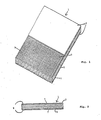
- FIG. 1 shows a part of a formwork sheet 1 according to the invention.
- FIG. 2 shows a section through the formwork sheet 1 according to FIG. 1.
- the formwork sheet 1 is made of PVC granulate which is obtained when copper is recovered from electrical cables. This waste PVC is foamed into PU foam.
- PVC granulate polystyrene or polyethylene waste or all plastic waste is also suitable, which corresponds to the PVC granulate in its physical or surface chemical properties and may be heavily contaminated.
- wood waste such as Sawdust can be poured or foamed into the PU foam.
- other foamable plastics such as Use thermoplastics.
- the formwork panel 1 shown in Fig. 1 and 2 is in front and back 3 and 5 with a reinforcement in Form of a metal mesh 7 provided.
- This reinforcement serves to improve the mechanical stability and can also consist of a glass or plastic fabric. Fibers or fibrous materials can also be embedded or foamed in as reinforcement.
- a protective coating 9 is applied over the metal mesh 7.
- the protective cover 9 consists of a particularly abrasion-resistant material, e.g. Polyurethane mixed with mineral or fibrous substances or metals. Even if this is not so clearly expressed in FIG. 1, the protective covering 9 completely covers the formwork panel 9, also and particularly on the edge sides 6 of the panel.
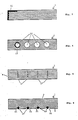
- Fig. 3 is a sectional view of a record 1, which is provided with an edge protector 11.
- the edge protector 11 is rectangular and covers the edge of the formwork panel 1 and, with approximately the same length, the front of the record 1.
- the edge protector 11 is either made of a particularly resistant plastic, such as Polyurethane, acrylic butadiene styrene, polystyrene or metal.
- Fig. 4 shows a section through a formwork panel 1 in the cavities 13 are provided.
- the cavities 13 serve on the one hand to reduce weight and, on the other hand, reinforcements, for example in the form of tubes 15, can be introduced into these cavities if required.
- Fig. 5 shows a further variant of the formwork sheet 1, in which a reinforcement in the form of flat iron 17 is poured or foamed.
- the flat band irons 17 are aligned parallel to the edge sides 6 and are completely enclosed by the plastic mass of the formwork panel.
- FIG. 6 A further embodiment of the formwork panel 1 is shown in FIG. 6.
- a reinforcement in the form of metal rods 19 is only attached to the back 5 of the formwork panel 1. So that this type of reinforcement does not require a change in the frame of a formwork panel equipped with it, the metal bars 19 run in recesses 21 in the formwork panel 1.
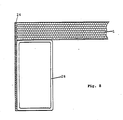
- the formwork panel has a frame 2b which is formed from a hollow profile with a rectangular cross section and rounded corners.
- the frame 2b is preferably made of steel or aluminum.
- the frame 26 can additionally be provided with cross struts, not shown, in a known manner.
- the formwork panel 1 is arranged with its rear side 5 on one of the shorter sides of the hollow profile 26 in such a way that the peripheral edge sides 6 of the formwork panel 1 are flush with one of the longer sides of the hollow profile or that the formwork panel projects slightly beyond the frame.
- This arrangement of the formwork panel on the frame of the formwork panel ensures that the formwork panels or their formwork panels installed in system formwork are practically closely spaced from one another.
- the edge sides 6 of the formwork panels are provided with a thin sealing lip 24.
- the embodiment of the formwork sheet according to FIG. 8 corresponds to the embodiment of FIG. 7 with the difference that the sealing lip 24 not only covers the edge sides 6 of the formwork sheet but also completely one of the longer sides of the hollow profile 26.
- the embodiment according to FIG. 8 enables a simplified cleaning of the formwork panel, since the largest part of the metal frame is covered by the sealing lip 24 made of plastic and dried concrete residues can be removed from plastic much more easily than from metal.
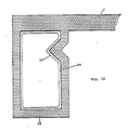
- the embodiment of the formwork panel according to FIG. 9 also corresponds to the embodiment according to FIG. 7 with the difference that the sealing lip 24 completely surrounds the frame 26 or the hollow profile 26. In this embodiment, it is completely prevented that concrete residues can solidify on the metal frame 26.
- the section through the formwork panel 1 is U-shaped. These legs or edge regions 28 of the plate 1 engage in a corresponding recess 30 in the frame 26, so that the edge sides 6 of the formwork plate 1 are flush with the frame 26 or protrude only slightly beyond the frame 26.
- the formwork sheet 1 therefore encloses the frame 26 like a cap.
- Fig. 11 shows a further elimination of a formwork panel with a formwork panel 1 which is U-shaped in section Legs or the extended edge regions 28 of the formwork panel 1 completely cover a long side of the rectangular hollow profile 26 in this embodiment.
- the recess 30 into which a corresponding thickening of the edge regions 28 of the formwork panel 1 engages is provided in a long side of the hollow profile 26 in this embodiment.
- the frame or the hollow profile 26 is completely integrated into the edge region 28 of the formwork panel 1 or the formwork panel 1 completely surrounds the hollow profile.
- the recess 30 and the associated thickening of the formwork panel are located on the inside of the frame 26.
- Fig. 13 is comparable to that of Fig. 11.
- the edge region 38 and the frame 26 are penetrated by two pins 32 which have a large projecting cap 34 in the region of the edge region 28.
- the edge area is protected from mechanical influences by the pins 32 or by the caps 34 located thereon. Pins 32 are removed immediately before assembly into the system formwork. Conventional dowel pins can then be inserted into the remaining openings.
- the formwork panel and frame are connected to one another by gluing.
- the formwork panel and frame can also be riveted or screwed in a conventional manner.
- Shaped parts, sheets or endless belts etc. made of foamable plastics with possibly contained granules, reinforcements etc. are either produced continuously on double belt systems (PU foams) or discontinuously using molds (polystyrene). Reactive resins are used here as well as expanding polystyrene particles that contain propellant gas.
- the formwork panels according to the invention can be produced using these methods, which, however, have to be specially modified.
- the resin components are first produced in a mixing plant.
- the aggregates of shredded plastic waste or recycling material are added to this mixture and mixed. This process must be adapted exactly to the belt speed of the production plant.
- the mixture is fed to the double belt system via special feed devices and metered in such a way that a constant amount is passed between the two belts.
- the double band can consist of perforated steel bands, which are supported from below by rollers, or chain-guided plates, which seal each other when they are next to each other, perforation is also required here.
- the machine produces an endless plate belt that can be cut lengthways and crossways after leaving the machine and reworked at the edges.
- the plate thickness is determined by the distance between the two tapes, which are sealed by side strips.
- the reinforcement will run in continuously at the beginning of the machine and will be fixed in the tension and compression zone and foamed into the panel web.
- release agents can either be applied continuously again, or separating media in the form of foils, nonwovens or the like run. with, which can also remain on the plate surface.
- the wear layers on the plate surface are applied after leaving the machine in the casting, spraying or rolling process, this can be done on the unprocessed belt as well as on the finished separated plates.
- the mixed mass is filled into molds, primarily of aluminum, which are provided with inwardly permeable nozzles which let steam pass through. into which steam is blown.
- the filled mold is closed and steamed in the exclave, cooled and then removed from the mold.
- reinforcements can also be inserted, and it is also possible to use a wide variety Foam edge profiles or give structures to the board surface.
- the wear layers can also be put directly into the mold or subsequently applied to the finished plate.
- the molds used can be designed to be stackable so that they can be steamed as a package.
- the frame of the formwork panel is part of the form for the manufacture of the formwork panel.
- the frame of the formwork panel is part of the form for the manufacture of the formwork panel.
Priority Applications (2)
| Application Number | Priority Date | Filing Date | Title |
|---|---|---|---|
| DE8916035U DE8916035U1 (de) | 1988-07-29 | 1989-07-27 | Schaltafel mit einer Schalplatte aus Kunststoff sowie Verfahren zu deren Herstellung |
| AT89113898T ATE83525T1 (de) | 1988-07-29 | 1989-07-27 | Schaltafel mit einer schalplatte aus kunststoff sowie verfahren zu deren herstellung. |
Applications Claiming Priority (2)
| Application Number | Priority Date | Filing Date | Title |
|---|---|---|---|
| DE3825900A DE3825900A1 (de) | 1988-07-29 | 1988-07-29 | Schaltafel mit einer schalplatte aus kunststoff sowie verfahren zu deren herstellung |
| DE3825900 | 1988-07-29 |
Publications (2)
| Publication Number | Publication Date |
|---|---|
| EP0353637A1 true EP0353637A1 (fr) | 1990-02-07 |
| EP0353637B1 EP0353637B1 (fr) | 1992-12-16 |
Family
ID=6359899
Family Applications (2)
| Application Number | Title | Priority Date | Filing Date |
|---|---|---|---|
| EP89908392A Pending EP0430966A1 (fr) | 1988-07-29 | 1989-07-27 | Plaque de coffrage avec un panneau de coffrage en plastique et son procede de fabrication |
| EP89113898A Expired - Lifetime EP0353637B1 (fr) | 1988-07-29 | 1989-07-27 | Elément de coffrage avec panneau de coffrage en matière plastique et procédé pour sa réalisation |
Family Applications Before (1)
| Application Number | Title | Priority Date | Filing Date |
|---|---|---|---|
| EP89908392A Pending EP0430966A1 (fr) | 1988-07-29 | 1989-07-27 | Plaque de coffrage avec un panneau de coffrage en plastique et son procede de fabrication |
Country Status (4)
| Country | Link |
|---|---|
| EP (2) | EP0430966A1 (fr) |
| AT (1) | ATE83525T1 (fr) |
| DE (2) | DE3825900A1 (fr) |
| WO (1) | WO1990001602A1 (fr) |
Cited By (21)
| Publication number | Priority date | Publication date | Assignee | Title |
|---|---|---|---|---|
| DE9013471U1 (fr) * | 1990-09-25 | 1990-12-06 | Bechtold, Heinz, 6121 Mossautal, De | |
| DE9017200U1 (fr) * | 1990-09-25 | 1991-04-25 | Bechtold, Heinz, 6121 Mossautal, De | |
| FR2679582A1 (fr) * | 1991-07-25 | 1993-01-29 | Husson Cie Sa Roland | Peau coffrante composite. |
| FR2715683A1 (fr) * | 1994-02-01 | 1995-08-04 | Outinord St Amand | Banche métallique avec peau coffrante interchangeable. |
| WO1996011102A1 (fr) * | 1994-10-10 | 1996-04-18 | Zodiac Europe S.A. | Paillasse et son procede de fabrication |
| WO1996032554A1 (fr) * | 1995-04-12 | 1996-10-17 | Providence Industries, L.L.C. | Plaque de panneau de coffrage pour beton reutilisable |
| DE19528938A1 (de) * | 1995-08-07 | 1997-02-13 | Johann Ganz | Chemiewerkstoff |
| EP0798431A1 (fr) * | 1996-03-29 | 1997-10-01 | Ferrozell Gmbh | Elément fait de déchets et son utilisation |
| WO1997045611A1 (fr) * | 1996-05-24 | 1997-12-04 | Antonius Gerardus De Hart | Element de banchage a utilisations repetees |
| WO1997049881A1 (fr) * | 1996-06-26 | 1997-12-31 | Gerhard Dingler | Element de construction et son procede de fabrication |
| US5792552A (en) * | 1996-04-12 | 1998-08-11 | Providence Industries, L.L.C. | Reusable concrete form panel sheeting |
| WO2000017469A1 (fr) * | 1998-09-21 | 2000-03-30 | Dae Yee Ind. Co., Ltd. | Panneau moule en beton |
| AU720937B2 (en) * | 1996-04-12 | 2000-06-15 | Providence Composite Technologies, Inc. | Reusable concrete form panel sheeting |
| EP1130192A2 (fr) * | 2000-02-21 | 2001-09-05 | Apsys Gesellschaft für anwendungstechnische Polyurethan-Systeme m.b.H | Panneau de coffrage |
| WO2004111368A1 (fr) * | 2003-06-17 | 2004-12-23 | Ulma C Y E, S. Coop. | Plaque en composite pour application dans des coffrages de beton et son procede d'obtention |
| ES2296445A1 (es) * | 2005-05-11 | 2008-04-16 | Ulma C Y E S. Coop | Tablero de encofrado con cantonera de proteccion y procedimiento de obtencion e integracion de dicha cantonera. |
| EP2060702A1 (fr) * | 2007-11-15 | 2009-05-20 | Sonoform AB | Moule pour couler du béton et procédé de réalisation d'un tel moule |
| CN101892739A (zh) * | 2010-07-13 | 2010-11-24 | 陈校兴 | 一次性建筑用模板 |
| CN101614072B (zh) * | 2008-08-15 | 2011-07-20 | 张锦 | 低发泡多层塑料建筑模板及制作方法 |
| CN102786750A (zh) * | 2012-08-02 | 2012-11-21 | 施冬 | 一种新型建筑塑料大梁底板的配方及其制备方法 |
| EP3526424B1 (fr) * | 2016-10-11 | 2021-12-01 | Bigrep GmbH | Système de coffrage modulaire destiné à la fabrication d'éléments en béton |
Families Citing this family (5)
| Publication number | Priority date | Publication date | Assignee | Title |
|---|---|---|---|---|
| FR2683575B1 (fr) * | 1991-11-07 | 1994-01-21 | Soframat | Panneau de coffrage de dalle. |
| FR2683574A1 (fr) * | 1991-11-07 | 1993-05-14 | Soframat | Panneau de coffrage en un materiau stratifie. |
| WO1996026819A1 (fr) * | 1995-02-27 | 1996-09-06 | Jacobsen Niels Joergen | Procede de fabrication de formes pour couler des articles de beton a l'aide d'une machine a parpaings |
| DE19607896C2 (de) * | 1996-03-01 | 2001-02-22 | Bruer Manfred | Aus Kunststoffschaum, insbesondere Polystyrolschaum, bestehende Schale einer verlorenen Schalung zur Errichtung von Betonwänden |
| CN115434505A (zh) * | 2022-08-15 | 2022-12-06 | 上海模新新材料科技有限公司 | 轻质现浇混凝土用新型复合材料建筑模板 |
Citations (10)
| Publication number | Priority date | Publication date | Assignee | Title |
|---|---|---|---|---|
| DE2012032A1 (de) * | 1970-03-13 | 1971-09-23 | Massenberg, Gert, 4300 Essen | Schalungstafel |
| DE2010003A1 (en) * | 1970-03-04 | 1971-09-23 | Reckli KG Wiemers & Co, 4350 Reck linghausen | Shuttering element |
| GB1471661A (en) * | 1974-05-06 | 1977-04-27 | Reed Malik Ltd | Shutters for supporting concrete or the like |
| DE2556224A1 (de) * | 1975-12-13 | 1977-06-23 | Phoenix Gummiwerke Ag | Schutzelement zur schalldaemmung |
| US4037816A (en) * | 1976-04-23 | 1977-07-26 | Scott Samuel C | Apparatus for forming a liner on a planar form means |
| FR2448605A1 (fr) * | 1979-02-09 | 1980-09-05 | Bouygues Sa | Panneau coffrant et ses applications |
| FR2468705A1 (fr) * | 1979-10-26 | 1981-05-08 | Halle Wohnungsbau | Coffrage de grande surface sans joints de raccord et procede pour sa fabrication |
| DE8617602U1 (de) * | 1986-07-02 | 1986-08-21 | NOE-Schaltechnik KG, 7334 Süssen | Schaltafel |
| DE8630650U1 (fr) * | 1986-11-15 | 1987-01-08 | Noe-Schaltechnik Kg, 7334 Suessen, De | |
| WO1987005353A1 (fr) * | 1986-03-05 | 1987-09-11 | Rolf Zollinger | Element en forme de planche, notamment pour coffrages a beton |
-
1988
- 1988-07-29 DE DE3825900A patent/DE3825900A1/de not_active Withdrawn
-
1989
- 1989-07-27 DE DE8989113898T patent/DE58903007D1/de not_active Expired - Fee Related
- 1989-07-27 WO PCT/DE1989/000490 patent/WO1990001602A1/fr not_active Application Discontinuation
- 1989-07-27 AT AT89113898T patent/ATE83525T1/de not_active IP Right Cessation
- 1989-07-27 EP EP89908392A patent/EP0430966A1/fr active Pending
- 1989-07-27 EP EP89113898A patent/EP0353637B1/fr not_active Expired - Lifetime
Patent Citations (10)
| Publication number | Priority date | Publication date | Assignee | Title |
|---|---|---|---|---|
| DE2010003A1 (en) * | 1970-03-04 | 1971-09-23 | Reckli KG Wiemers & Co, 4350 Reck linghausen | Shuttering element |
| DE2012032A1 (de) * | 1970-03-13 | 1971-09-23 | Massenberg, Gert, 4300 Essen | Schalungstafel |
| GB1471661A (en) * | 1974-05-06 | 1977-04-27 | Reed Malik Ltd | Shutters for supporting concrete or the like |
| DE2556224A1 (de) * | 1975-12-13 | 1977-06-23 | Phoenix Gummiwerke Ag | Schutzelement zur schalldaemmung |
| US4037816A (en) * | 1976-04-23 | 1977-07-26 | Scott Samuel C | Apparatus for forming a liner on a planar form means |
| FR2448605A1 (fr) * | 1979-02-09 | 1980-09-05 | Bouygues Sa | Panneau coffrant et ses applications |
| FR2468705A1 (fr) * | 1979-10-26 | 1981-05-08 | Halle Wohnungsbau | Coffrage de grande surface sans joints de raccord et procede pour sa fabrication |
| WO1987005353A1 (fr) * | 1986-03-05 | 1987-09-11 | Rolf Zollinger | Element en forme de planche, notamment pour coffrages a beton |
| DE8617602U1 (de) * | 1986-07-02 | 1986-08-21 | NOE-Schaltechnik KG, 7334 Süssen | Schaltafel |
| DE8630650U1 (fr) * | 1986-11-15 | 1987-01-08 | Noe-Schaltechnik Kg, 7334 Suessen, De |
Cited By (25)
| Publication number | Priority date | Publication date | Assignee | Title |
|---|---|---|---|---|
| DE9013471U1 (fr) * | 1990-09-25 | 1990-12-06 | Bechtold, Heinz, 6121 Mossautal, De | |
| DE9017200U1 (fr) * | 1990-09-25 | 1991-04-25 | Bechtold, Heinz, 6121 Mossautal, De | |
| FR2679582A1 (fr) * | 1991-07-25 | 1993-01-29 | Husson Cie Sa Roland | Peau coffrante composite. |
| FR2715683A1 (fr) * | 1994-02-01 | 1995-08-04 | Outinord St Amand | Banche métallique avec peau coffrante interchangeable. |
| WO1996011102A1 (fr) * | 1994-10-10 | 1996-04-18 | Zodiac Europe S.A. | Paillasse et son procede de fabrication |
| WO1996032554A1 (fr) * | 1995-04-12 | 1996-10-17 | Providence Industries, L.L.C. | Plaque de panneau de coffrage pour beton reutilisable |
| DE19528938A1 (de) * | 1995-08-07 | 1997-02-13 | Johann Ganz | Chemiewerkstoff |
| DE19528938C2 (de) * | 1995-08-07 | 1999-01-14 | Johann Ganz | Verfahren zur Herstellung einer Formmasse |
| EP0798431A1 (fr) * | 1996-03-29 | 1997-10-01 | Ferrozell Gmbh | Elément fait de déchets et son utilisation |
| US5792552A (en) * | 1996-04-12 | 1998-08-11 | Providence Industries, L.L.C. | Reusable concrete form panel sheeting |
| AU720937B2 (en) * | 1996-04-12 | 2000-06-15 | Providence Composite Technologies, Inc. | Reusable concrete form panel sheeting |
| WO1997045611A1 (fr) * | 1996-05-24 | 1997-12-04 | Antonius Gerardus De Hart | Element de banchage a utilisations repetees |
| WO1997049881A1 (fr) * | 1996-06-26 | 1997-12-31 | Gerhard Dingler | Element de construction et son procede de fabrication |
| US6148575A (en) * | 1996-06-26 | 2000-11-21 | Dingler; Gerhard | Structural member and process for producing a structural member |
| WO2000017469A1 (fr) * | 1998-09-21 | 2000-03-30 | Dae Yee Ind. Co., Ltd. | Panneau moule en beton |
| EP1130192A2 (fr) * | 2000-02-21 | 2001-09-05 | Apsys Gesellschaft für anwendungstechnische Polyurethan-Systeme m.b.H | Panneau de coffrage |
| EP1130192A3 (fr) * | 2000-02-21 | 2003-03-26 | Apsys Gesellschaft für anwendungstechnische Polyurethan-Systeme m.b.H | Panneau de coffrage |
| WO2004111368A1 (fr) * | 2003-06-17 | 2004-12-23 | Ulma C Y E, S. Coop. | Plaque en composite pour application dans des coffrages de beton et son procede d'obtention |
| ES2221801A1 (es) * | 2003-06-17 | 2005-01-01 | Ulma C Y E, S. Coop. | Tablero de composite para aplicacion en encofrados de hormigon y procedimiento para la obtencion del mismo. |
| ES2296445A1 (es) * | 2005-05-11 | 2008-04-16 | Ulma C Y E S. Coop | Tablero de encofrado con cantonera de proteccion y procedimiento de obtencion e integracion de dicha cantonera. |
| EP2060702A1 (fr) * | 2007-11-15 | 2009-05-20 | Sonoform AB | Moule pour couler du béton et procédé de réalisation d'un tel moule |
| CN101614072B (zh) * | 2008-08-15 | 2011-07-20 | 张锦 | 低发泡多层塑料建筑模板及制作方法 |
| CN101892739A (zh) * | 2010-07-13 | 2010-11-24 | 陈校兴 | 一次性建筑用模板 |
| CN102786750A (zh) * | 2012-08-02 | 2012-11-21 | 施冬 | 一种新型建筑塑料大梁底板的配方及其制备方法 |
| EP3526424B1 (fr) * | 2016-10-11 | 2021-12-01 | Bigrep GmbH | Système de coffrage modulaire destiné à la fabrication d'éléments en béton |
Also Published As
| Publication number | Publication date |
|---|---|
| WO1990001602A1 (fr) | 1990-02-22 |
| EP0430966A1 (fr) | 1991-06-12 |
| EP0353637B1 (fr) | 1992-12-16 |
| DE3825900A1 (de) | 1990-02-01 |
| ATE83525T1 (de) | 1993-01-15 |
| DE58903007D1 (de) | 1993-01-28 |
Similar Documents
| Publication | Publication Date | Title |
|---|---|---|
| EP0353637B1 (fr) | Elément de coffrage avec panneau de coffrage en matière plastique et procédé pour sa réalisation | |
| EP0010121B1 (fr) | Panneaux préfabriqués autoportants et leur procédé de fabrication | |
| DE2756820A1 (de) | Mischmaterialbausteinelement und verfahren zu seiner herstellung | |
| EP1048630A2 (fr) | Matières plastiques pour l'industrie de construction | |
| DE102008034749B3 (de) | Holzwerkstoffplatte | |
| EP0640030B1 (fr) | Procede de fabrication d'un element de construction leger se presentant sous forme de panneau ou de carreau | |
| DE2246938A1 (de) | Bauplatte | |
| DE102005050190A1 (de) | Hybridplatte | |
| DE4244535C2 (de) | Strukturmaterial aus miteinander verbundenen Partikeln, das von Kanälen durchsetzt ist | |
| DE4434012C1 (de) | Verfahren zur Herstellung eines im Bauwesen zu verwendenden Dämmformteils | |
| DE2451692A1 (de) | Sandwich-fassadenplatte und verfahren und vorrichtung zu ihrer herstellung | |
| AT401268B (de) | Schaumstoffelement, insbesondere formteil aus einer oder mehreren platten aus schaumstoff und verfahren zu seiner herstellung | |
| EP0453620B1 (fr) | Bloc interassemblable moulé et procédé pour la fabrication d'un tel bloc | |
| DE4141334C2 (de) | Wanne mit verstärktem Boden | |
| DE3005707A1 (de) | Grossformatige bauplatte und verfahren zu deren herstellung, sowie aus diesen platten bestehendes wandelement | |
| DE1800773A1 (de) | Verbindung fuer zusammengesetzte Tafeln mit einer Schaumstoffseele und mittels dieser hergestellte Tafeln | |
| DE3310227C2 (de) | Verfahren und zur Herstellung eines Fassadenelementes aus Beton mit strukturierter Sichtbetonoberfläche | |
| DE2758696A1 (de) | Formkoerper aus gummigranulat und bindemittel | |
| DE20302496U1 (de) | Schalungselement | |
| DE19817669C2 (de) | Kleinformatige Fassaden-Verkleidungsplatten | |
| AT214627B (de) | Verfahren zum Herstellen von durch einen Rahmen versteiften Kunststoffplatten und nach diesem Verfahren hergestellte Platte | |
| DE102004056130B4 (de) | Holzfaserdämmstoffplatte mit veredelter Oberfläche | |
| DE4200400A1 (de) | Verfahren zur herstellung eines dachziegels und dachziegel hergestellt nach dem verfahren | |
| DD200809A1 (de) | Strukturplatte fuer fussboeden und wandverkleidungen | |
| DE19804770A1 (de) | Lärmschutzwände und schallabsorbierende Bekleidungen |
Legal Events
| Date | Code | Title | Description |
|---|---|---|---|
| PUAI | Public reference made under article 153(3) epc to a published international application that has entered the european phase |
Free format text: ORIGINAL CODE: 0009012 |
|
| AK | Designated contracting states |
Kind code of ref document: A1 Designated state(s): ES GR |
|
| 17P | Request for examination filed |
Effective date: 19900802 |
|
| 17Q | First examination report despatched |
Effective date: 19910506 |
|
| XX | Miscellaneous (additional remarks) |
Free format text: VERBUNDEN MIT 89908392.7/0430966 (EUROPAEISCHE ANMELDENUMMER/VEROEFFENTLICHUNGSNUMMER) DURCH ENTSCHEIDUNG VOM 26.07.91. |
|
| RAP1 | Party data changed (applicant data changed or rights of an application transferred) |
Owner name: PERI GMBH |
|
| RIN1 | Information on inventor provided before grant (corrected) |
Inventor name: FEHR, WERNER |
|
| GRAA | (expected) grant |
Free format text: ORIGINAL CODE: 0009210 |
|
| AK | Designated contracting states |
Kind code of ref document: B1 Designated state(s): AT BE CH DE ES FR GB GR IT LI LU NL SE |
|
| PG25 | Lapsed in a contracting state [announced via postgrant information from national office to epo] |
Ref country code: SE Effective date: 19921216 Ref country code: NL Effective date: 19921216 Ref country code: GR Free format text: LAPSE BECAUSE OF FAILURE TO SUBMIT A TRANSLATION OF THE DESCRIPTION OR TO PAY THE FEE WITHIN THE PRESCRIBED TIME-LIMIT Effective date: 19921216 Ref country code: GB Effective date: 19921216 Ref country code: ES Free format text: THE PATENT HAS BEEN ANNULLED BY A DECISION OF A NATIONAL AUTHORITY Effective date: 19921216 Ref country code: BE Effective date: 19921216 |
|
| REF | Corresponds to: |
Ref document number: 83525 Country of ref document: AT Date of ref document: 19930115 Kind code of ref document: T |
|
| XX | Miscellaneous (additional remarks) |
Free format text: VERBUNDEN MIT 89908392.7/0430966 (EUROPAEISCHE ANMELDENUMMER/VEROEFFENTLICHUNGSNUMMER) DURCH ENTSCHEIDUNG VOM 26.07.91. |
|
| ET | Fr: translation filed | ||
| REF | Corresponds to: |
Ref document number: 58903007 Country of ref document: DE Date of ref document: 19930128 |
|
| ITF | It: translation for a ep patent filed |
Owner name: SOCIETA' ITALIANA BREVETTI S.P.A. |
|
| NLV1 | Nl: lapsed or annulled due to failure to fulfill the requirements of art. 29p and 29m of the patents act | ||
| GBV | Gb: ep patent (uk) treated as always having been void in accordance with gb section 77(7)/1977 [no translation filed] |
Effective date: 19921216 |
|
| PG25 | Lapsed in a contracting state [announced via postgrant information from national office to epo] |
Ref country code: LU Free format text: LAPSE BECAUSE OF NON-PAYMENT OF DUE FEES Effective date: 19930731 Ref country code: LI Effective date: 19930731 Ref country code: CH Effective date: 19930731 |
|
| PLBE | No opposition filed within time limit |
Free format text: ORIGINAL CODE: 0009261 |
|
| STAA | Information on the status of an ep patent application or granted ep patent |
Free format text: STATUS: NO OPPOSITION FILED WITHIN TIME LIMIT |
|
| 26N | No opposition filed | ||
| REG | Reference to a national code |
Ref country code: CH Ref legal event code: PL |
|
| PGFP | Annual fee paid to national office [announced via postgrant information from national office to epo] |
Ref country code: FR Payment date: 19960712 Year of fee payment: 8 |
|
| PGFP | Annual fee paid to national office [announced via postgrant information from national office to epo] |
Ref country code: AT Payment date: 19970731 Year of fee payment: 9 |
|
| PG25 | Lapsed in a contracting state [announced via postgrant information from national office to epo] |
Ref country code: FR Free format text: LAPSE BECAUSE OF NON-PAYMENT OF DUE FEES Effective date: 19980331 |
|
| REG | Reference to a national code |
Ref country code: FR Ref legal event code: ST |
|
| PG25 | Lapsed in a contracting state [announced via postgrant information from national office to epo] |
Ref country code: AT Free format text: LAPSE BECAUSE OF NON-PAYMENT OF DUE FEES Effective date: 19980727 |
|
| PGFP | Annual fee paid to national office [announced via postgrant information from national office to epo] |
Ref country code: DE Payment date: 20000913 Year of fee payment: 12 |
|
| PG25 | Lapsed in a contracting state [announced via postgrant information from national office to epo] |
Ref country code: DE Free format text: LAPSE BECAUSE OF NON-PAYMENT OF DUE FEES Effective date: 20020501 |
|
| PG25 | Lapsed in a contracting state [announced via postgrant information from national office to epo] |
Ref country code: IT Free format text: LAPSE BECAUSE OF NON-PAYMENT OF DUE FEES Effective date: 20050727 |