EP0330646B1 - Verfahren zum Stranggiessen eines dünnen Bandes oder einer dünnen Bramme sowie Vorrichtung zur Durchführung des Verfahrens - Google Patents
Verfahren zum Stranggiessen eines dünnen Bandes oder einer dünnen Bramme sowie Vorrichtung zur Durchführung des Verfahrens Download PDFInfo
- Publication number
- EP0330646B1 EP0330646B1 EP89890013A EP89890013A EP0330646B1 EP 0330646 B1 EP0330646 B1 EP 0330646B1 EP 89890013 A EP89890013 A EP 89890013A EP 89890013 A EP89890013 A EP 89890013A EP 0330646 B1 EP0330646 B1 EP 0330646B1
- Authority
- EP
- European Patent Office
- Prior art keywords
- casting
- drum
- drums
- arrangement according
- casting drum
- Prior art date
- Legal status (The legal status is an assumption and is not a legal conclusion. Google has not performed a legal analysis and makes no representation as to the accuracy of the status listed.)
- Expired - Lifetime
Links
- 238000005266 casting Methods 0.000 title claims abstract description 156
- 238000000034 method Methods 0.000 title claims abstract description 12
- 229910052751 metal Inorganic materials 0.000 claims abstract description 20
- 239000002184 metal Substances 0.000 claims abstract description 20
- 229910000831 Steel Inorganic materials 0.000 claims abstract description 4
- 239000010959 steel Substances 0.000 claims abstract description 4
- 230000015572 biosynthetic process Effects 0.000 claims abstract description 3
- 238000001816 cooling Methods 0.000 claims description 8
- 239000000155 melt Substances 0.000 claims description 7
- 238000003825 pressing Methods 0.000 claims description 2
- 230000006698 induction Effects 0.000 claims 2
- 230000005499 meniscus Effects 0.000 claims 1
- 239000007788 liquid Substances 0.000 description 6
- 238000009749 continuous casting Methods 0.000 description 4
- 238000007711 solidification Methods 0.000 description 4
- 230000008023 solidification Effects 0.000 description 4
- 230000002093 peripheral effect Effects 0.000 description 3
- 229910001338 liquidmetal Inorganic materials 0.000 description 2
- 229910045601 alloy Inorganic materials 0.000 description 1
- 239000000956 alloy Substances 0.000 description 1
- 229910052782 aluminium Inorganic materials 0.000 description 1
- XAGFODPZIPBFFR-UHFFFAOYSA-N aluminium Chemical compound [Al] XAGFODPZIPBFFR-UHFFFAOYSA-N 0.000 description 1
- 238000010276 construction Methods 0.000 description 1
- 238000009434 installation Methods 0.000 description 1
- 238000004519 manufacturing process Methods 0.000 description 1
- 239000000463 material Substances 0.000 description 1
- 229910001092 metal group alloy Inorganic materials 0.000 description 1
- 150000002739 metals Chemical class 0.000 description 1
- 235000011837 pasties Nutrition 0.000 description 1
- 239000011819 refractory material Substances 0.000 description 1
- 230000001360 synchronised effect Effects 0.000 description 1
- 239000010409 thin film Substances 0.000 description 1
- 230000007704 transition Effects 0.000 description 1
Images

Classifications
-
- B—PERFORMING OPERATIONS; TRANSPORTING
- B22—CASTING; POWDER METALLURGY
- B22D—CASTING OF METALS; CASTING OF OTHER SUBSTANCES BY THE SAME PROCESSES OR DEVICES
- B22D11/00—Continuous casting of metals, i.e. casting in indefinite lengths
- B22D11/06—Continuous casting of metals, i.e. casting in indefinite lengths into moulds with travelling walls, e.g. with rolls, plates, belts, caterpillars
- B22D11/0622—Continuous casting of metals, i.e. casting in indefinite lengths into moulds with travelling walls, e.g. with rolls, plates, belts, caterpillars formed by two casting wheels
Definitions
- EP-A 0 154 250 discloses a method and a continuous casting plant of this type with which thin strips or thin slabs can be produced.
- the second casting drum is in this case provided directly at the pouring point of the melt onto the first casting drum, so that the liquid sump formed between the pouring drums is located directly at the pouring point.
- the first casting drum is surrounded along its circumference in addition to the second casting drum by a series of rollers which guide and cool the cast strand.
- the melt feed takes place here on the upwardly moving side of the rotating first casting drum.
- the strand still has a liquid core over a large part of the circumference of the first casting drum.
- the extension of the liquid core over the first casting drum requires a complex construction of the known system, since the strand must be supported and guided particularly carefully in this area.
- a method for casting a strip from lead and its alloys is known from US Pat. No. 2,693,012.
- the metal melt is then poured onto a drum surface of a first casting drum, which first casting drum is opposite a second casting drum, a casting gap with the thickness of the strip being formed between the casting drums.
- the strand shells formed on the drum surfaces are moved to the casting gap.
- the total thickness of which corresponds to the thickness of the cast strip there is a zone in which the molten metal is pasty or plastic.
- AT-B 331 435 describes how to apply melt to a rotating casting drum.
- a complete solidification of the metal strip on the upwardly moving part of the casting drum must occur immediately after contact with the surface of the casting drum.
- only extremely thin strips of aluminum can be produced. The thickness of the strips largely depends on the depth of the melt pool at the transition point to the drum surface.
- the invention aims to avoid these disadvantages and has as its object to provide a method and an apparatus for carrying out the method of the types described in the introduction, which produce a strip in a thickness between 1 and 20 mm with high operational reliability for different steel qualities and different Allow tape thicknesses, the tape having exactly the desired thickness.
- This object is achieved in that the sump is formed at a distance from the pouring of the molten metal onto the drum surface of the first casting drum, between the sump and the pouring on the drum surface of the first casting drum, a strand shell of a predetermined thickness is formed and that the casting gap on the circumference the first casting drum is brought into a position in which the maximum length of the two strand shells formed on the drum surfaces corresponds in total to at least the thickness of the cast strip or slab.
- a device of the type described at the outset for carrying out the method is characterized in that the pouring spout rests on the peripheral side of the first casting drum facing away from the second casting drum.
- the second casting drum in the Support frame can be moved in the direction of and in the direction of the mounting of the first casting drum by means of an adjusting device.
- the pivoting device expediently comprises a screw spindle acting on the support frame.
- a preferred embodiment is characterized in that the pivoting device comprises an elastically deformable traction means which is fastened to the support frame at a distance from the axis of the first casting drum and which can be actuated by means of a pressure medium cylinder.
- the pouring spout is expediently equipped with an overflow weir and the level of the melt level in the vessel can be adjusted with respect to the overflow weir.
- the limiting devices are each advantageously formed by a plate that can be pressed laterally onto the end faces of the casting drums by means of an adjusting device.
- the limiting devices are each formed by an endless belt which can be pressed against the end faces of the casting drum by means of a pressure plate, the limiting devices advantageously being provided with cooling.
- At least one limiting device is advantageously formed by a plate which is adapted to the drum surfaces of the casting drum and can be displaced along the latter by means of an adjusting device.
- the support frame can be pivoted from the horizontal by about 80 ° while moving the casting gap into a position inclined to about 80 ° .
- an inductor is expediently arranged between the pouring spout and the apex of the first casting drum or an inductor is arranged between the apex of the first casting drum and the casting gap.
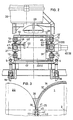
- FIG. 1 shows a schematically illustrated side view of a continuous casting plant
- Fig. 2 shows a partially sectioned view in the direction of arrow II of Fig. 1.
- 3 shows a detail of FIG. 1.
- the continuous casting installation has a first casting drum 1, which is provided with an internal cooling system (not shown), which is rotatably mounted about a horizontal axis 2 and can be driven in the direction of arrow 4 by means of a drive 3.
- the axis 2 is supported on the casting platform 5 by means of support rollers 6 rotatably mounted on the casting platform 5.
- a support frame 10 engages on each of the two end faces 8, 9 of the first casting drum 1 and can be pivoted about the axis 2 of the first casting drum 1 by means of bearings 11.
- the support frame 10 has on each end face 8, 9 of the first casting drum 1 lying and radially extending from the axis 2 of the first casting drum 1 frame 12, each in a disc-shaped, concentrically arranged to the first casting drum 1 end piece 13, each on two of the support rollers 6 rests, pass over.
- the frames 12 are rigidly connected to each other to the support frame 10 by means of cross members 12 '.
- a flexible traction means acts on the outside, for example a band 14 or a rope, which is guided over a deflection roller 15 rotatably mounted on the casting platform 5 and is attached at its end to a piston rod 16 of a pressure medium cylinder 17.
- the pressure medium cylinder 17 is articulated on the casting platform 5. When this pressure medium cylinder 17 is acted upon, the support frame 10 with the frame 12 can thus be pivoted about the axis 2 of the first casting drum 1 into the position shown in broken lines in FIG. 1.
- a threaded spindle 18 is provided for each frame 12, which engages on the frame 12 with one end.
- a nut 19 which is arranged in an articulated manner on the casting platform 5 and is penetrated by the threaded spindle 18, can be driven by means of a worm drive 20.
- the frames 12 of the support frames 10 each hold a bearing 21 of a second casting drum 22, these bearings 21 being displaceable in the direction of the first casting drum 1 or in the opposite direction by means of pressure medium cylinders 23, which are each supported on the end crosshead 24 of the frame 12. This makes it possible to set a casting gap 25 of a predetermined size between the two casting drums 1 and 22.
- a pouring spout 27 of a distributor 28 can be placed on the drum surface 7 of the first casting drum 1 that moves upward when the first casting drum 1 rotates.
- a dip pipe 29 of a pouring ladle 30 positioned above the distributor 28 opens into the distributor 28.
- the distributor 28 and the pouring spout 27 are lined with refractory material 31.
- the pouring spout 27 is equipped with an overflow weir 32.
- the level 33 of the molten metal 34 poured into the distributor 28 lies at the height 35 of the overflow weir 32, so that a thin film 36 of molten metal 34 flows over the overflow weir 32 onto the drum surface 7 of the first casting drum 1.
- a part of the molten metal solidifies on the casting drum 1, a strand shell 37 becoming increasingly thicker over the circumference of the casting drum.
- a part of the still molten metal melt flows into the casting gap 25 formed by the two casting drums 1 and 22 and forms a liquid sump 38 there as a result of material jams.
- a strand shell 39 likewise forms on the drum surface of the second casting drum 22 and is moved by means of a drive 40 to the casting gap 25 by rotating the second casting drum 22 in the opposite direction of rotation to the first casting drum 1 and the same or slightly different peripheral speed.
- the casting gap 25 corresponds in its thickness 41 to the thickness 42 of the strip 43 drawn off.
- the position of the casting gap 25 and the cooling of the casting drum are selected such that the thicknesses 44, 45 of the the casting drums 1 and 22 formed strand shells 37, 39 at the location of the casting gap 25 in total at least the thickness 42 of the drawn strip 43 correspond. This ensures that there is no longer any liquid core within the strip 43 which has been drawn off and that support of the strip 43 after removal from the casting drums 1 and 22 is only necessary for guiding it.
- a lateral delimitation of the casting gap 25 can, as illustrated in FIG. 2 on the left half of the figure, be realized by a plate 46, optionally cooled, which can be pressed onto the end faces of the casting drums 1 and 22 in the region of the casting gap 25 and which are each on one end face of both casting drums 1 and 22 abrasive.
- a pressure cylinder 47 for pressing the plate 46 against the end faces is articulated to the frame 12 of the support frame 10.
- An embodiment shown in the right half of the figure in FIG. 2 for the lateral delimitation of the casting gap has a continuous endless belt 48 which is pressed against the end faces of the casting drums 1 and 22 with a pressure plate 49 in the area of the casting gap 25.
- the belt 48 rotates at approximately the circumferential speed of the casting drums 1 and 22. This avoids excessive grinding between the end faces of the casting drums 1 and 22 and the limiting device.
- a cooling device 50 for the strip is shown schematically in FIG. 2.
- the idler rollers 51 of the belt 48 are attached to the frame 12 of the support frame 10.
- the position of the support frame 10 or its frame 12 is adjusted so that the thicknesses of the strand shells 37, 39 formed on the surfaces of the casting drums in the casting gap 25 total at least the thickness 42 of the finished strip 43 correspond.
- the frames 12, as illustrated by dash-dotted lines in FIG. 1 can be inclined with their longitudinal axis 52 by approximately 80 ° with respect to the horizontal, ie the connecting plane of the axes of the two casting drums 1 and 22 can be moved from the horizontal plane to an approximately 80 ° inclined position.
- inductors 53 can be arranged inside the first casting drum 1, which are then expediently provided in a stationary manner and depending on the length over which the liquid Metal melt 34 extends over the surface of the first casting drum, can be put into operation.
Landscapes
- Engineering & Computer Science (AREA)
- Mechanical Engineering (AREA)
- Continuous Casting (AREA)
Applications Claiming Priority (2)
| Application Number | Priority Date | Filing Date | Title |
|---|---|---|---|
| DE3802202 | 1988-01-26 | ||
| DE3802202A DE3802202A1 (de) | 1988-01-26 | 1988-01-26 | Verfahren zum stranggiessen eines duennen bandes oder einer duennen bramme sowie vorrichtung zur durchfuehrung des verfahrens |
Publications (2)
| Publication Number | Publication Date |
|---|---|
| EP0330646A1 EP0330646A1 (de) | 1989-08-30 |
| EP0330646B1 true EP0330646B1 (de) | 1990-10-31 |
Family
ID=6345995
Family Applications (1)
| Application Number | Title | Priority Date | Filing Date |
|---|---|---|---|
| EP89890013A Expired - Lifetime EP0330646B1 (de) | 1988-01-26 | 1989-01-19 | Verfahren zum Stranggiessen eines dünnen Bandes oder einer dünnen Bramme sowie Vorrichtung zur Durchführung des Verfahrens |
Country Status (6)
| Country | Link |
|---|---|
| US (2) | US4960164A (enExample) |
| EP (1) | EP0330646B1 (enExample) |
| JP (1) | JP2930597B2 (enExample) |
| DE (1) | DE3802202A1 (enExample) |
| ES (1) | ES2019139B3 (enExample) |
| GR (1) | GR3001402T3 (enExample) |
Families Citing this family (5)
| Publication number | Priority date | Publication date | Assignee | Title |
|---|---|---|---|---|
| AT397478B (de) * | 1991-10-03 | 1994-04-25 | Voest Alpine Stahl | Verfahren und vorrichtung zum stranggiessen eines dünnen bandes oder einer dünnen bramme |
| IT1290603B1 (it) * | 1997-05-02 | 1998-12-10 | Voest Alpine Ind Anlagen | Cilindro di colata |
| CN100400198C (zh) * | 2003-08-07 | 2008-07-09 | 李华伦 | 镁薄板带材双辊高速连铸生产线 |
| CN1647870B (zh) * | 2004-01-20 | 2010-04-14 | 李华伦 | 金属薄板双辊异步铸轧机 |
| US20080088065A1 (en) * | 2006-10-12 | 2008-04-17 | Fujifilm Corporation | Cellulose resin film, method for producing the same and film product thereof |
Family Cites Families (14)
| Publication number | Priority date | Publication date | Assignee | Title |
|---|---|---|---|---|
| US2450428A (en) * | 1944-03-23 | 1948-10-05 | Clarence W Hazelett | Strip forming apparatus |
| US2693012A (en) * | 1950-09-08 | 1954-11-02 | Gen Motors Corp | Method and apparatus for manufacturing sheet material |
| AT331435B (de) * | 1972-05-18 | 1976-08-25 | Alcan Res & Dev | Verfahren zur herstellung von gegossenen metallstreifen |
| US3817317A (en) * | 1972-07-20 | 1974-06-18 | Collins S | Four-high roll casting machine |
| YU43229B (en) * | 1980-05-09 | 1989-06-30 | Battelle Development Corp | Device for continuous band casting |
| JPS58209451A (ja) * | 1982-05-31 | 1983-12-06 | Mitsubishi Heavy Ind Ltd | 薄板の連続鋳造方法 |
| JPS5997743A (ja) * | 1982-11-26 | 1984-06-05 | Furukawa Battery Co Ltd:The | 鉛蓄電池用格子基板の製造方法 |
| CH666842A5 (de) * | 1984-03-01 | 1988-08-31 | Concast Service Union Ag | Verfahren und vorrichtung zum kontinuierlichen giessen von metallen in form von band zwischen zwei gekuehlten achsparallelen trommeln. |
| JPS61229445A (ja) * | 1985-04-03 | 1986-10-13 | Ishikawajima Harima Heavy Ind Co Ltd | 連続鋳造方法及び装置 |
| JPS61253149A (ja) * | 1985-04-12 | 1986-11-11 | Nippon Kinzoku Kogyo Kk | 金属薄板の連続鋳造による製造装置 |
| JPS6238745A (ja) * | 1985-08-13 | 1987-02-19 | Nippon Yakin Kogyo Co Ltd | 金属薄板の直接製造装置 |
| JPS63101056A (ja) * | 1986-10-17 | 1988-05-06 | Kawasaki Steel Corp | 急冷金属薄帯の製造方法および装置 |
| DE3721510A1 (de) * | 1987-06-30 | 1989-01-19 | Fink Gerdinand | Vorrichtung und verfahren zum bandgiessen von stahl |
| DE3725010C1 (de) * | 1987-07-29 | 1988-09-29 | Krupp Stahl Ag | Verfahren zum Herstellen duenner Metallbaender |
-
1988
- 1988-01-26 DE DE3802202A patent/DE3802202A1/de active Granted
-
1989
- 1989-01-12 US US07/296,533 patent/US4960164A/en not_active Expired - Lifetime
- 1989-01-19 EP EP89890013A patent/EP0330646B1/de not_active Expired - Lifetime
- 1989-01-19 ES ES89890013T patent/ES2019139B3/es not_active Expired - Lifetime
- 1989-01-26 JP JP1017403A patent/JP2930597B2/ja not_active Expired - Lifetime
-
1990
- 1990-05-14 US US07/522,549 patent/US5035279A/en not_active Expired - Fee Related
-
1991
- 1991-01-30 GR GR91400117T patent/GR3001402T3/el unknown
Also Published As
| Publication number | Publication date |
|---|---|
| ES2019139B3 (es) | 1991-06-01 |
| JP2930597B2 (ja) | 1999-08-03 |
| US5035279A (en) | 1991-07-30 |
| GR3001402T3 (en) | 1992-09-25 |
| DE3802202A1 (de) | 1989-08-03 |
| EP0330646A1 (de) | 1989-08-30 |
| JPH01224146A (ja) | 1989-09-07 |
| US4960164A (en) | 1990-10-02 |
| DE3802202C2 (enExample) | 1992-11-12 |
Similar Documents
| Publication | Publication Date | Title |
|---|---|---|
| DE69706510T2 (de) | Verfahren und Vorrichtung zum Giessen von Metallbändern | |
| DE69419593T3 (de) | Giessen eines kontinuierlichen stahlbandes auf eine oberfläche mit bestimmter rauhigkeit | |
| EP1181997A1 (de) | Verfahren und Vorrichtung zum kontinuierlichen Giessen von Stahlband aus Stahlschmelze | |
| DE4313041C2 (de) | Gießen von Metallband | |
| EP0114293B1 (de) | Verfahren und Vorrichtung zur Einstellung der Konizität von Schmalseitenwänden von Stranggiesskokillen | |
| DE69912027T2 (de) | Bandgiessanlage | |
| EP0330646B1 (de) | Verfahren zum Stranggiessen eines dünnen Bandes oder einer dünnen Bramme sowie Vorrichtung zur Durchführung des Verfahrens | |
| DE3707897C2 (enExample) | ||
| DE3142099A1 (de) | Verfahren und vorrichtung zum stranggiessen von metall unter gesteuerter belastung | |
| EP3993921B1 (de) | Schmelzezuführung für bandgussanlagen | |
| EP0450391B1 (de) | Vorrichtung zur Stützung eines Metallgiessstranges, insbesondere zur Weichreduktion bei einer Vorband-Giessanlage | |
| DE3440236C2 (enExample) | ||
| LU85485A1 (de) | Vorrichtung und verfahren zum kontinuierlichen giessen von metall | |
| DE19852275C2 (de) | Anlage und Verfahren zum Bandgießen | |
| DE2853868C2 (de) | Verfahren zum Stranggießen von Stahl sowie dementsprechend hergestellter Stahlstrang | |
| EP1057557B1 (de) | Verfahren und Vorrichtung zum kontinuierlichen Giessen von Metall | |
| DE19638101B4 (de) | Bandguß | |
| DE4307464C2 (de) | CSP-Stranggießmaschine für die kontinuierliche Herstellung von Dünnbrammen aus Stahl | |
| WO2002090019A1 (de) | VERFAHREN UND VORRICHTUNG ZUM STRANGGIEssEN VON BLÖCKEN, BRAMMEN ODER DÜNNBRAMMEN | |
| DE3802203C2 (enExample) | ||
| EP0384151B1 (de) | Anlage zur Herstellung von Stahlband | |
| EP1078703A1 (de) | Bandgiessmaschine mit zwei Giessrollen | |
| EP0679460B1 (de) | Regulierbare elektromagnetische Stranggiesskokille | |
| DE69621657T2 (de) | Stranggussmaschine mit einem drehrad | |
| DE3028247A1 (de) | Vorrichtung zur erzeugung von eisen-ausgangsmaterialien |
Legal Events
| Date | Code | Title | Description |
|---|---|---|---|
| PUAI | Public reference made under article 153(3) epc to a published international application that has entered the european phase |
Free format text: ORIGINAL CODE: 0009012 |
|
| AK | Designated contracting states |
Kind code of ref document: A1 Designated state(s): BE CH ES FR GB GR IT LI LU NL SE |
|
| 17P | Request for examination filed |
Effective date: 19891002 |
|
| 17Q | First examination report despatched |
Effective date: 19900208 |
|
| GRAA | (expected) grant |
Free format text: ORIGINAL CODE: 0009210 |
|
| AK | Designated contracting states |
Kind code of ref document: B1 Designated state(s): BE CH ES FR GB GR IT LI LU NL SE |
|
| ET | Fr: translation filed | ||
| ITF | It: translation for a ep patent filed | ||
| GBT | Gb: translation of ep patent filed (gb section 77(6)(a)/1977) | ||
| PLBE | No opposition filed within time limit |
Free format text: ORIGINAL CODE: 0009261 |
|
| STAA | Information on the status of an ep patent application or granted ep patent |
Free format text: STATUS: NO OPPOSITION FILED WITHIN TIME LIMIT |
|
| 26N | No opposition filed | ||
| REG | Reference to a national code |
Ref country code: GR Ref legal event code: FG4A Free format text: 3001402 |
|
| ITTA | It: last paid annual fee | ||
| EPTA | Lu: last paid annual fee | ||
| EAL | Se: european patent in force in sweden |
Ref document number: 89890013.9 |
|
| PGFP | Annual fee paid to national office [announced via postgrant information from national office to epo] |
Ref country code: LU Payment date: 20001201 Year of fee payment: 13 |
|
| PGFP | Annual fee paid to national office [announced via postgrant information from national office to epo] |
Ref country code: GB Payment date: 20001212 Year of fee payment: 13 |
|
| PGFP | Annual fee paid to national office [announced via postgrant information from national office to epo] |
Ref country code: GR Payment date: 20001221 Year of fee payment: 13 |
|
| PGFP | Annual fee paid to national office [announced via postgrant information from national office to epo] |
Ref country code: NL Payment date: 20001222 Year of fee payment: 13 |
|
| PGFP | Annual fee paid to national office [announced via postgrant information from national office to epo] |
Ref country code: SE Payment date: 20001227 Year of fee payment: 13 |
|
| PGFP | Annual fee paid to national office [announced via postgrant information from national office to epo] |
Ref country code: FR Payment date: 20010103 Year of fee payment: 13 |
|
| PGFP | Annual fee paid to national office [announced via postgrant information from national office to epo] |
Ref country code: BE Payment date: 20010118 Year of fee payment: 13 |
|
| PGFP | Annual fee paid to national office [announced via postgrant information from national office to epo] |
Ref country code: ES Payment date: 20010122 Year of fee payment: 13 |
|
| REG | Reference to a national code |
Ref country code: GB Ref legal event code: IF02 |
|
| PG25 | Lapsed in a contracting state [announced via postgrant information from national office to epo] |
Ref country code: LU Free format text: LAPSE BECAUSE OF NON-PAYMENT OF DUE FEES Effective date: 20020119 Ref country code: GB Free format text: LAPSE BECAUSE OF NON-PAYMENT OF DUE FEES Effective date: 20020119 |
|
| PG25 | Lapsed in a contracting state [announced via postgrant information from national office to epo] |
Ref country code: SE Free format text: LAPSE BECAUSE OF NON-PAYMENT OF DUE FEES Effective date: 20020120 |
|
| PG25 | Lapsed in a contracting state [announced via postgrant information from national office to epo] |
Ref country code: ES Free format text: LAPSE BECAUSE OF NON-PAYMENT OF DUE FEES Effective date: 20020121 |
|
| PG25 | Lapsed in a contracting state [announced via postgrant information from national office to epo] |
Ref country code: BE Free format text: LAPSE BECAUSE OF NON-PAYMENT OF DUE FEES Effective date: 20020131 |
|
| BERE | Be: lapsed |
Owner name: VOEST-ALPINE INDUSTRIEANLAGENBAU G.M.B.H. Effective date: 20020131 |
|
| PG25 | Lapsed in a contracting state [announced via postgrant information from national office to epo] |
Ref country code: NL Free format text: LAPSE BECAUSE OF NON-PAYMENT OF DUE FEES Effective date: 20020801 |
|
| PG25 | Lapsed in a contracting state [announced via postgrant information from national office to epo] |
Ref country code: GR Free format text: LAPSE BECAUSE OF NON-PAYMENT OF DUE FEES Effective date: 20020812 |
|
| EUG | Se: european patent has lapsed |
Ref document number: 89890013.9 |
|
| GBPC | Gb: european patent ceased through non-payment of renewal fee |
Effective date: 20020119 |
|
| PG25 | Lapsed in a contracting state [announced via postgrant information from national office to epo] |
Ref country code: FR Free format text: LAPSE BECAUSE OF NON-PAYMENT OF DUE FEES Effective date: 20020930 |
|
| NLV4 | Nl: lapsed or anulled due to non-payment of the annual fee |
Effective date: 20020801 |
|
| REG | Reference to a national code |
Ref country code: FR Ref legal event code: ST |
|
| PGFP | Annual fee paid to national office [announced via postgrant information from national office to epo] |
Ref country code: CH Payment date: 20021230 Year of fee payment: 15 |
|
| REG | Reference to a national code |
Ref country code: ES Ref legal event code: FD2A Effective date: 20031022 |
|
| PG25 | Lapsed in a contracting state [announced via postgrant information from national office to epo] |
Ref country code: LI Free format text: LAPSE BECAUSE OF NON-PAYMENT OF DUE FEES Effective date: 20040131 Ref country code: CH Free format text: LAPSE BECAUSE OF NON-PAYMENT OF DUE FEES Effective date: 20040131 |
|
| REG | Reference to a national code |
Ref country code: CH Ref legal event code: PL |
|
| PG25 | Lapsed in a contracting state [announced via postgrant information from national office to epo] |
Ref country code: IT Free format text: LAPSE BECAUSE OF NON-PAYMENT OF DUE FEES;WARNING: LAPSES OF ITALIAN PATENTS WITH EFFECTIVE DATE BEFORE 2007 MAY HAVE OCCURRED AT ANY TIME BEFORE 2007. THE CORRECT EFFECTIVE DATE MAY BE DIFFERENT FROM THE ONE RECORDED. Effective date: 20050119 |