EP0316947B1 - Dispositif et procédé pour impression sérigraphique de plaques - Google Patents
Dispositif et procédé pour impression sérigraphique de plaques Download PDFInfo
- Publication number
- EP0316947B1 EP0316947B1 EP88119230A EP88119230A EP0316947B1 EP 0316947 B1 EP0316947 B1 EP 0316947B1 EP 88119230 A EP88119230 A EP 88119230A EP 88119230 A EP88119230 A EP 88119230A EP 0316947 B1 EP0316947 B1 EP 0316947B1
- Authority
- EP
- European Patent Office
- Prior art keywords
- screen
- scraper
- board
- squeegee
- printing
- Prior art date
- Legal status (The legal status is an assumption and is not a legal conclusion. Google has not performed a legal analysis and makes no representation as to the accuracy of the status listed.)
- Expired - Lifetime
Links
Images


Classifications
-
- B—PERFORMING OPERATIONS; TRANSPORTING
- B41—PRINTING; LINING MACHINES; TYPEWRITERS; STAMPS
- B41F—PRINTING MACHINES OR PRESSES
- B41F15/00—Screen printers
- B41F15/08—Machines
- B41F15/0804—Machines for printing sheets
- B41F15/0813—Machines for printing sheets with flat screens
- B41F15/0818—Machines for printing sheets with flat screens with a stationary screen and a moving squeegee
-
- B—PERFORMING OPERATIONS; TRANSPORTING
- B41—PRINTING; LINING MACHINES; TYPEWRITERS; STAMPS
- B41F—PRINTING MACHINES OR PRESSES
- B41F15/00—Screen printers
- B41F15/14—Details
- B41F15/16—Printing tables
- B41F15/18—Supports for workpieces
- B41F15/26—Supports for workpieces for articles with flat surfaces
-
- B—PERFORMING OPERATIONS; TRANSPORTING
- B41—PRINTING; LINING MACHINES; TYPEWRITERS; STAMPS
- B41F—PRINTING MACHINES OR PRESSES
- B41F15/00—Screen printers
- B41F15/14—Details
- B41F15/44—Squeegees or doctors
- B41F15/46—Squeegees or doctors with two or more operative parts
-
- H—ELECTRICITY
- H05—ELECTRIC TECHNIQUES NOT OTHERWISE PROVIDED FOR
- H05K—PRINTED CIRCUITS; CASINGS OR CONSTRUCTIONAL DETAILS OF ELECTRIC APPARATUS; MANUFACTURE OF ASSEMBLAGES OF ELECTRICAL COMPONENTS
- H05K3/00—Apparatus or processes for manufacturing printed circuits
- H05K3/10—Apparatus or processes for manufacturing printed circuits in which conductive material is applied to the insulating support in such a manner as to form the desired conductive pattern
- H05K3/12—Apparatus or processes for manufacturing printed circuits in which conductive material is applied to the insulating support in such a manner as to form the desired conductive pattern using thick film techniques, e.g. printing techniques to apply the conductive material or similar techniques for applying conductive paste or ink patterns
- H05K3/1216—Apparatus or processes for manufacturing printed circuits in which conductive material is applied to the insulating support in such a manner as to form the desired conductive pattern using thick film techniques, e.g. printing techniques to apply the conductive material or similar techniques for applying conductive paste or ink patterns by screen printing or stencil printing
- H05K3/1233—Methods or means for supplying the conductive material and for forcing it through the screen or stencil
-
- H—ELECTRICITY
- H05—ELECTRIC TECHNIQUES NOT OTHERWISE PROVIDED FOR
- H05K—PRINTED CIRCUITS; CASINGS OR CONSTRUCTIONAL DETAILS OF ELECTRIC APPARATUS; MANUFACTURE OF ASSEMBLAGES OF ELECTRICAL COMPONENTS
- H05K2203/00—Indexing scheme relating to apparatus or processes for manufacturing printed circuits covered by H05K3/00
- H05K2203/01—Tools for processing; Objects used during processing
- H05K2203/0104—Tools for processing; Objects used during processing for patterning or coating
- H05K2203/0139—Blade or squeegee, e.g. for screen printing or filling of holes
-
- H—ELECTRICITY
- H05—ELECTRIC TECHNIQUES NOT OTHERWISE PROVIDED FOR
- H05K—PRINTED CIRCUITS; CASINGS OR CONSTRUCTIONAL DETAILS OF ELECTRIC APPARATUS; MANUFACTURE OF ASSEMBLAGES OF ELECTRICAL COMPONENTS
- H05K2203/00—Indexing scheme relating to apparatus or processes for manufacturing printed circuits covered by H05K3/00
- H05K2203/15—Position of the PCB during processing
- H05K2203/1518—Vertically held PCB
-
- H—ELECTRICITY
- H05—ELECTRIC TECHNIQUES NOT OTHERWISE PROVIDED FOR
- H05K—PRINTED CIRCUITS; CASINGS OR CONSTRUCTIONAL DETAILS OF ELECTRIC APPARATUS; MANUFACTURE OF ASSEMBLAGES OF ELECTRICAL COMPONENTS
- H05K2203/00—Indexing scheme relating to apparatus or processes for manufacturing printed circuits covered by H05K3/00
- H05K2203/15—Position of the PCB during processing
- H05K2203/1572—Processing both sides of a PCB by the same process; Providing a similar arrangement of components on both sides; Making interlayer connections from two sides
Definitions
- the present invention relates to an apparatus for and a method of screen printing on boards, and more particularly to screen printing apparatus and method for coating or marking such boards with a resist or with patterns or symbols by squeegeeing with use of mechanical drive means.
- screen printing is used herein and in the appended claims in a broad sense of the term including coating the entire surface of a screen with a resist.
- the conventional screen printing machines used are of the type wherein the screen is positioned horizontally, and the printing means including the screen and a squeegee is provided only on the upper side of the board to be printed.
- the printing means including the screen and a squeegee is provided only on the upper side of the board to be printed.
- each surface must be printed separately. This method of printing is likely to produce a difference in the result achieved between the front and rear surface and is therefore undesirable.
- EP-A 0 135 682 discloses a screen printing technique in which a screen is held upright and a squeegee is disposed on each side of the screen. According to the disclosed technique, one of the squeegees is provided to apply an ink to one side of the screen and the other squeegee is provided to scrape the ink-coated screen or recover the ink from the other side.
- the two squeegees are mounted on a common, vertically movable member and are vertically moved together.
- This arrangement is such that both sides of the board cannot be screen-printed at the same time with a printing means arranged for both sides of the board and including a screen vertically held and squeegees on the front and rear side of the screen, because the squeegee on the rear side of the screen hinders the printing.
- This application mode is limited and cannot accomplish variuos results which include, for example, the following: the ink is uniformly filled into the screen meshes while a small amount of ink is oozed out on the rear surface of the screen; the ink is uniformly deposited on the screen surface to form a coating of required sufficient thickness; or the ink is applied evenly to the front surface of the screen while the residual ink is removed on the rear side.
- the spatula used cannot function variously to achieve the results of application.
- this technique fails to meet the requirements in screen-printing on a board for printing wiring boards that the ink be applied in a manner to achieve various results according to the humidity and temperature of the operation site and the viscosity of the ink used.
- DE-A 12 99 660 describes a screen printing technique in which screens are provided on the front and rear sides of a board held upright, and squeegees are disposed in a symmetrical position on the frontside of the screens, so that the squeegees can be used at the same time for application of ink and squeegeeing.
- This technique has the same drawback as disclosed in the above abstract, namely inability to use the squeegees for various functions to achieve various results of the ink application.
- An object of the present invention is to provide mechanized screen printing apparatus and method for preparing printed wiring boards, as adapted to satisfactorily print or coat a multiplicity of such boards free of variations from board to board.
- Another object of the invention is to provide screen printing apparatus and method for preparing printed wiring boards, as adapted to print or coat both surfaces of the board with equivalent results.
- the second scraper When the screen is to be scraped by the first and second scrapers at the same time with the former position below the latter, the second scraper first cleans the rear surface of the screen, ink is then supplied to the front surface of the screen, and the first scraper is thereafter moved over the front surface to uniformly fill the ink into the meshes and cause a small amount of the ink to steep through the screen to the rear surface. Accordingly, the ink on the front and rear surfaces is prevented from drying to diminish the variation in the viscosity of ink on the screen.
- a multiplicity of boards for printed wiring can therefore be printed or coated uniformly by the screen printing apparatus with use of the mechanically driven squeegee.
- the mode of screen printing wherein the first and second scrapers are caused to scrape the screen at the same time with the former positioned below the latter is especially suitable for coating the entire surface of the board, for example, with a photoresist.
- the first scraper is positioned about 10 to 200 mm, preferably about 70 to about 120 mm, below the second scraper.
- the screen can be scraped by the two scrapers while being given a degree of cushioning property, whereby the ink can be filled in with the first scraper effectively.
- the ink is deposited, by squeegeeing, i.e. printing or coating, on the surface of the board to be printed to form an ink layer or coating having a sufficient thickness as required.
- the first and second scrapers have such properties that they will not be bent by being pressed into contact with the screen. The screen can then be scraped by the scrapers with an improved result while being given the abovementioned cushioning property.
- the ink is filled into the screen meshes by the first scraper on the screen front surface, and the second scraper removes an excess of the ink forced out on the screen rear surface by the filling operation. Accordingly, the ink can be applied to sufficient thickness as required, permitting the squeegee to form a sharp image by printing. Moreover, a multiplicity of boards can be thus printed uniformly.
- the mode of screen printing wherein the first and second scrapers are caused to scrape the screen at the same time with the former positioned above the latter is especially suitable for printing patterns.
- the first scraper is positioned about 10 to about 200 mm, preferably about 70 to about 120 mm, above the second scraper.
- the screen can be scraped by the two scrapers while being given a degree of cushioning property, whereby the excessive ink can be removed from the rear surface by the second scraper effectively.
- the first and second scrapers have such properties that they will not be bent by being pressed into contact with the screen. The screen can then be scraped by the scrapers with an improved result while being given the cushioning property.
- the ink is filled into the screen meshes by the first scraper from the screen front surface, and the second scraper wipes off an excess of the ink from the screen rear surface. Consequently, a multiplicity of boards can be printed or coated all uniformly. Further even when the squeegee is moved once, a satisfactory print or coating can be obtained.
- the mode of screen printing wherein the first and second scrapers are used as positioned at the same level for simultaneous scraping is suitable for coating or masking a resist on substrates and printing patterns and symbols alike.
- the squeegee be about 6 to about 10 mm in thickness, be projected from the support plate therefor by a length of about 20 to about 40 mm, have a hardness of about 60 to about 90 HS, and be used under a pressure of about 300 to about 1500 g/cm2 and at an angle (squeegeeing angle) of about 60 to about 90 degrees relative to the surface of the board to be printed.
- the squeegee is usable without creating faults, such as blank spots free of deposition of ink and produced by the stepped portions of such irregularities along the squeegeeing direction and shadows at corners of projections.
- the ink penetrates into the screens on both sides to the same degree since the printing means is of the upright type. Accordingly, the board can be printed or coated at the same time on both surfaces thereof with the same result by the printing means arranged on both sides.
- the squeegee and the first scraper may be arranged, with the squeegee positioned slightly above or below the first scraper, and moved together upward and downward for the operation of the squeegee during the movement in one direction and for the first and second scrapers to scrape the screen during movement in the other direction.
- the first and second scrapers are positioned away from the screen during squeegee, and the squeegee is held away from the screen during scraping.
- the lower of these members is held at a distance of about 1 mm away from the screen front surface to a position where the member is in contact with the front surface without exerting any substantial pressure thereon.
- the scraper or the squeegee at the lower level serves to prevent the ink from flowing down the vertical screen. If the clearance is not greater than about 1 mm, the ink which is viscous will not flow down through the clearance. When thus prevented from flowing down, the ink will not be wasted or will not soil the neighboring articles or machine parts.
- the squeegee may be used for squeegeeing with its axis positioned obliquely with respect to the direction of advance of the squeegee. This mode of squeegeeing results in the following.
- the board surface to be printed or coated is likely to have indentations, for example, owing to etching for forming a circuit.
- indentations always include those positioned as substantially distributed in the direction of advance of the squeegee and having a depth of tens of micrometers. If the squeegee is mechanically driven with its axis positioned perpendicular to the direction of advance of the squeegee in the usual manner for a board having these indentations, the squeegee passes over the indented stepped portions in line contact therewith and therefore vibrates, producing wavelike variations in density on the printed or coated surface.
- the acute angle between the axis of the squeegee and the direction of advance is greater than about 80 degrees. If the angle is smaller, the ink flows as deflected toward one side of the squeegee along the oblique axis of the squeegee, consequently producing density irregularities on the printed or coated surface with respect to the lengthwise direction of the squeegee. This problem can be overcome when the angle is greater than about 80 degrees.
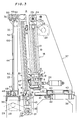
- the illustrated screen printing apparatus or machine for preparing printed circuit boards comprises means 33 for holding a board 100 upright in position, and printing means disposed upright for each surface of the board 100 held in position by the holding means 33.
- the printing means which is best shown in Fig. 3, is designated collectively by the character A.
- Fig. 3 shows the printing means A for only the right side of the board 100.
- the printing means A comprises a screen 1, a squeegee 2, a first scraper 3 positioned slightly below the squeegee 2 for scraping the front surface (opposed to the squeegee 2) of the screen 1, and a second scraper 4 for scraping the rear surface (opposed to the board 100) of the screen 1.
- the squeegee 2 is secured at its base portion by a support plate 5 of metal or the like which is a kind of jig.
- the support plate 5 for the squeegee 2 is mounted at its opposite ends on carriers 6, 6 slidable on a pair of guide members 10, 10 extending upright.
- the support plate 5 is movable forward or rearward (laterally in Figs. 2 and 3) by adjusting screws 7, whereby the squeegeeing pressure of the squeegee 2 is adjustable.
- the support plate 5 is further shiftable by solenoids 11 between two positions, i.e., a position where the squeegee 2 is pressed into contact with the surface of the screen 1 and a position away from the screen rightward in Fig. 3.
- the first scraper 3 resembles a spatula, is similar to the squeegee 2 in basic construction, and has a support plate 8 which is attached at its opposite ends to the carriers 6, 6.
- Indicated at 9 are adjusting screws for moving the support plate 8 forward or rearward to thereby adjust the degree of pressing contact of the scraper 3 with the screen surface.
- the scraper 3 is also shiftable between two positions, i.e., a position where the scraper is in pressing contact with the screen surface and a position away from the screen rightward of Fig. 3.
- Indicated at 12 are solenoids for shifting the scraper 3 between these two positions.
- the scraper 3 has such properties that it will not be bent by the pressing contact with the screen 1.
- it is made of a metal plate or synthetic resin plate having such rigidity or hardness.
- the second scraper 4 also resembles a spatula.
- the scraper 4 is secured to a support plate 13, which in turn is attached at its opposite ends to carriers 15, 15 slidable on a pair of upright guide members 14, 14.
- the scraper 4 is also adjustable in the degree of pressing contact with the rear surface of the screen 1 and shiftable between two positions, i.e., a position where it is in pressing contact with the screen rear surface and a position away from the screen leftward in Fig. 3.
- Indicated at 16 are screws for adjusting the degree of pressing contact, and at 17 solenoids for shifting the scraper between the two positions.
- the scraper 4 has such properties that it will not be bent by the pressing contact with the screen 1.
- it is made of a metal plate or synthetic resin plate having such rigidity or hardness.
- the guide members 10, 10 are combined with a cross member 10′ to make a frame 18 carrying a bracket 34.
- the frame 18 has an ink tray 51 at its lower portion.
- a support frame 19 with the screen 1 extending thereover is secured to the bracket 34.
- the bracket 34 is adjustable in position laterally in Fig. 2 by adjusting screws 35 (see Fig. 1), whereby the clearance between the screen 1 and the surface of the board 100 is adjustable for squeegeeing.
- the frame 18 is suspended at its upper side from a frame structure 37 mounted on the base 36 of the screen printing machine and is pivotally movable laterally in Figs. 2 and 3 about the axis of the shaft 25 to be described later.
- the frame 18 is so movable by an air cylinder-plunger unit 20.
- the unit 20 has one end pivoted to the lower portion of the frame 18 and the other end to the frame structure 37.
- the frame structure 37 is slidable by an air cylinder-plunger unit 42 on guide rails 41 installed on the base 36 and extending laterally in Figs. 2 and 3.
- Indicated at 43 are slide shoes for the frame structure 37.
- Each of the carriers 6, 6 is mounted by a ball thread 38 on a feed screw 21 provided on the guide member 10 and extending therealong.
- the feed screws 21, 21 are driven in synchronism by the forward or reverse rotation of a motor 22 mounted on the frame structure 37 on the base, through a transmission chain or timing belt 23, transmission gear 24, coupling shaft 25 and transmission gear 26, whereby the carriers 6, 6 are moved upward or downward in synchronism.
- the guide members 14, 14 are fixed to the base 36 in a specified position and combined with the base 36 to form a frame 39.
- the frame 39 is so sized as to permit the frame 18 to pass therethrough.
- Each carrier 15 is mounted by a ball thread 40 on a feed screw 27 mounted on and extending along the guide member 14.
- the feed screws 27, 27 are driven in synchronism by the forward or reverse rotation of a motor 28 by way of a transmission chain or timing belt 29, transmission gear 30, coupling shaft 31 and transmission gear 32, whereby the carriers 15, 15 are moved upward or downward in synchronism.
- the motors 22 and 28 are rotatable at the same speed.
- the carriers 6, 6 are adapted to advance at the same speed as the carriers 15, 15.
- the screen printing machine further includes a frame 44 provided for the board 100 and having vertically opposed holders 33, 33.
- the frame 44 is slidable by an air cylinder-plunger unit 48 on upper and lower guide rails 46, 47 extending in parallel horizontally laterally of Fig. 1. These guide rails 46, 47 are mounted in position on the assembly of the base 36 and another base 45 adjacent thereto.
- Indicated at 49 is a slide shoe for the frame 44, and at 50 a roller on the frame 44.
- the left end of the frame 44, and the slide shoe and the roller at this end are not shown in Fig. 1 to simplify the drawing for a better understanding.
- the shoe and roller are arranged substantially symmetrically with those provided at the right end as shown in Fig. 1.
- the board 100 is supported between the holders 33 and 33 on the frame 44 mounted on the base 45. Grooves 52, 52 are formed in the respective holders 33, 33 for inserting the opposite ends of the board 100 therein.
- the board 100 supported is brought from the solid-line position to the phantom-line position in Fig. 1 by the movement of the frame 44 by the air cylinder-plunger unit 48.
- ink for coating or marking the board with a resist, pattern or symbols is applied to the surface of the screen by the following procedure.
- the frame structure 37 is brought to a standby position (Fig. 3) to thereby cause the frame 18 and the screen 1 to wait in position. Further the assembly of the squeegee 2 and the first scraper 3 is brought to a standby position (Fig. 3) on the frame 18, and the second scraper 4 is caused to wait in position (Fig. 3) on the frame 39. With the parts thus in standby state, the squeegee 2 is positioned away from the surface of the screen 1, the first scraper 3 is lightly in pressing contact with the screen surface, and the second scraper 4 is slightly rearwardly (toward the center of the machine) away from the plane of the screen rear surface.
- a suitable amount of ink is supplied to the upper side of the forward end of the first scraper 3 in the standby state by a suitable method.
- the motor 28 is driven to raise the second scraper 4.
- the motor 22 is driven to raise the first scraper 3 and the squeegee 2 while allowing the second scraper 4 to continue rising.
- the squeegee 2 is held away from the screen, and the first scraper 3 is held in light pressing contact with the screen surface.
- the scraper 4 Upon the second scraper 4 reaching the selected level relative to the first scraper 3, the scraper 4 is shifted into light pressing contact with the screen rear surface and thereafter held in this pressing contact position until the assembly of the squeegee 2 and the first scraper 3 rises to a specified position.
- both surfaces of the screen 1 are scraped at the same time by the scrapers 3 and 4 as positioned at the same level or with the former positioned the specified distance below or above the latter.
- the ink is applied to the surface of the screen 1, and the screen rear surface is cleaned.
- the motor 22 Upon the squeegee 2 and the first scraper 3 rising to the specified position, the motor 22 is deenergized to stop the squeegee 2 and the first scraper 3. The second scraper 4 thereafter still continues its upward movement to reach a level slightly above the stopped position of the first scraper 3. During the continued upward movement, the second scraper 4 is held away from the screen rear surface. Upon the second scraper 4 reaching the specified level, the motor 28 is reversely driven to lower the scraper 4 as held away from the screen rear surface to the original standby position. The squeegee 2 and the first scraper 3 remain in their stopped position.
- the board 100 When the ink has been applied to the screen 1, the board 100 is brought to a specified position and printed or coated by the squeegee 2 as will be described below.
- the frame structure 37 is moved leftward in Fig. 3 by the air cylinder-plunger unit 42 to advance the frame 18 along with the screen 1 to the specified position. (This step will be referred to as "step F".)
- the screen 1 and the frame 18 are thereafter pivotally moved by the air cylinder-plunger unit 20 toward the board 100 to a position immediately in front of the board surface to be printed.
- the first scraper 3 is shifted to a position away from the screen 1. (This shift of the scraper 3 will be referred to as "R shift”.)
- the squeegee 2 is pressed against the front surface of the board 100 with the screen 1 interposed therebetween.
- the carriers 6, 6 are lowered to operate the squeegee 2 for squeegeeing. Consequently, the board 100 is coated or marked with a resist, or with a pattern or symbols.
- the screen 1 and the frame 18 are returned to the original specified or standby position by the return of the frame structure 37 to its original position.
- the squeegee 2 is shifted to the position away from the screen 1.
- the first scraper 3 is brought into light pressing contact with the screen surface again.
- the printed or coated board 100 is returned to the position where it was initially set in the machine, and is removed from the holder 33, 33.
- step F and the following steps are thereafter repeated again except for the R shift.
- the ink is applied to the screen prior to squeegeeing and a new board is transported to the specified position in the same manner as already described.
- the assembly of the squeegee 2 and the first scraper 3, the second scraper 4, the screen 1 and the frame 18 are controlled in sequence for the required movement or operation using sensors, limit switches or like suitable means for detecting these components as brought to predetermined positions during the operation. When required, timers are also usable for this purpose. These detecting means and sequence control will be apparent to one skilled in the art and are therefore not shown.
- the squeegee 2 for use in the foregoing screen printing or coating operation is about 6 to about 10 mm in thickness t, about 20 to about 40 mm in the length l of projection from the support plate 5 and about 60 to about 90 HS in hardness and is used at a squeegeeing pressure P of about 300 to about 1500 g/cm2, more preferably about 700 to about 1000 g/cm2 and at a squeegeeing angle ⁇ 1 of about 60 to about 90 degrees. (See Fig. 4 for t, l, P and ⁇ 1.)
- the first scraper 3 may be positioned a small distance, preferably about 30 to about 120 mm, above the squeegee 2 during the descent of the squeegee 2 or during the squeegeeing step (accordingly, with the first scraper 3 out of scraping contact with the screen) while being located within a range C from a position about 1 mm away from the screen surface to a position where the scraper 3 is substantially out of scraping contact with the screen surface.
- the scraper 3 then prevents the ink 60 from flowing down the screen 1 (see Fig. 5).
- the squeegee 2 may be disposed a small distance, preferably about 30 to about 120 mm, above the scraper 3 and located within the same range C as above relative to the screen 1, with the scraper 3 in scraping contact with the screen 1 during the descent of the squeegee 2 and the scraper 3.
- This modification is schematically shown in Fig. 6.
- the modification of Fig. 6 is substantially identical with the embodiment of Figs. 1 to 3 in construction except that the squeegee 2 and the scraper 3 of the modification are arranged in reverse relation to those of the embodiment.
- the squeegee 2 is operated for squeegeeing during the upward movement.
- the squeegeeing step is performed during the upward movement, and the scraper 3 scrapes the screen during the downward movement.
- the squeegee 2 may be operated for squeegeeing with its axis positioned obliquely with respect to the direction of advance of the squeegee (Fig. 7).
- the acute angle ⁇ 2 between the axis and the direction of advance of the squeegee 2 is greater than about 80 degrees and is generally about 80 to about 89 degrees.
- the modification of Fig. 7 is substantially identical with the embodiment of Figs. 1 to 3 in construction except that the squeegee 2 is disposed obliquely.
- the board 100 which is held by the means described with reference to Figs. 1 to 3 can alternatively be held by modified means as seen in Figs. 8 and 9.
- the screen 1 and the holders 33, 33 are sized to correspond to the greatest printing or squeegeeing size available with the screen printing machine.
- At least one of the holders 33, 33 is vertically adjustable in its installed position.
- the holders 33, 33 are each in the form of a plate having a slightly larger thickness than the board 100.
- the upper holder only is adjustable.
- the adjustable holder has vertical slots 330 and is fastened in place with bolts 331 inserted through the respective slots 330. Indicated at 332 are fastening bolts for the stationary holder.
- the embodiment of Figs. 8 and 9 has substantially the same construction as the one shown in Figs. 1 to 3 except for the modified board holding means.
- the adjustable holder is adjusted in position in conformity with the vertical dimension of the bcard.
- the opposed holders 33, 33 serve to hold boards ranging from a maximum size to a minimum size.
- Fig. 8 shows the holders 33, 33 as used for holding a board of minimum size, which is represented by the area marked with crisscross lines.
- a board of maximum size is indicated in a dot-and-dash line.
- the difference of a board of small size from the maximum squeegeeing size in horizontal dimension is compensated for by a dummy board 101 inserted between the holders 33, 33.
- the dummy board 101 has the same thickness as the board 100.
- the dummy board may be slidable for insertion.
- the screen printing machine equipped with the modified holding means is suitable for coating boards with a resist over the entire surface thereof.
- the modification assures that a screen sized to correspond to the maximum squeegeeing size available is usable for boards of varying sizes smaller than the maximum size for coating the board with a resist over the entire surface thereof without impairing the releasability of the screen from the board. If a screen of large size is used as it is for printing boards of smaller size, the screen is not releasable from the board smoothly to impair the quality of the print obtained. It is well known to one skilled in the art that screens of varying sizes are available for use in printing boards of different sizes in corresponding relation thereto.
- the modified holding means to be described below is more desirable than the other holding means.
- Each of two holding means disposed one above the other, comprises a first clamp member in the form of a thin plate, and a second clamp member in the form of a thin plate and lapped over and joined to the first clamp member.
- the first and second clamp members clamp the end of the board therebetween.
- One of the holding means is stationary, while the other holding means can be pulled vertically by a device such as an air cylinder-plunger unit.
- the second clamp member is flexible at least at its forward end portion, which is openable relative to the first clamp member.
- An adhesive tape or adhesive is affixed or applied to at least one of the opposed inner surfaces of the forward end portions of the first and second clamp members, which are therefore separably adhered to each other.
- Fig. 10 to 12 show an example of such modified holding means.
- the upper holder 33 can be pulled vertically or upward by an air cylinder-plunger unit 53 which is fixed to the frame 44.
- the unit 53 has a horizontally extending connecting member 54 having a groove 55 which is constricted at its inlet.
- the upper holder which can be pulled, has a horizontally extending enlarged base portion 333 which is inserted into the groove 55 of the member 54, whereby the holder can be connected to the unit 53 by the member 54.
- the first clamp member is indicated at 33a, the second clamp member at 33b, and the openable end portion of the second clamp member 33b at 33c.
- the adhesive tape or adhesive is indicated at 56.
- the first clamp members 33a, 33a have positioning pins 57, 57 for the ends of the board 100 to be held.
- the end faces of the pins 57 are flush with the plane of the board 100.
- the embodiment including the modification of Figs. 10 to 12 has substantially the same construction as the embodiment of Figs 1 to 3 except for the modified holding means.
- the board 100 is held by the holders 33, 33 shown in Figs. 10 to 12 by the following procedure.
- the forward end portions 33c, 33c of the second clamp members 33b, 33b of the upper and lower holders 33, 33 are opened, and the pins 57, 57 on the first clamp members 33a, 33a are fitted in pin holes 58, 58 formed in the upper and lower ends of the board 100, whereby the board 100 is supported by the holders 33, 33.
- the end portion 33c of each second clamp member 33b is then pressed against the inner surface of the first clamp member 33a at the corresponding end portion thereof to adhere the end portion 33c to the member 33a. Consequently, the upper and lower ends of the board 100 are clamped between the first and second clamp members 33a, 33b and 33a, 33b of the upper and lower holders 33, 33, respectively.
- the board 100 thus clamped is then tensioned by causing the air cylinder-plunger unit 53 to pull the upper holder 33.
- the layer of adhesive 56 adhering the clamp member 33a to the end portion 33c exhibits high bond strength against the tensile force acting along the plane of the adhesive layer, i.e., in the direction of the tension, so that the board 100 can be subjected to a sufficient tensile load. Accordingly, the board 100, although thin, can be firmly held straight between the upper and lower holders 33 and 33 without loosening or bending. The board held free of loosening or bending permits the screen to be released from the board smoothly when it is to be separated therefrom.
- the first and second clamp members 33a, 33b of each holder 33 which are joined together as lapped over each other are in the form of a thin plate.
- Each second clamp member 33b is flexible at least at its forward end portion 33c.
- the clamped portion of the thin board be free of projections to the greatest possible extent.
- This requirement can be fulfilled by the construction of the holder 33. Since the first and second clamp members 33a, 33b are lapped over each other and joined together in the form of a thin plate, the projection produced by the board end clamped between these members can be small and is allowable. Moreover, since at least the end portion 33c of the second clamp member 33b is flexible, the projection of the end portion 33c created by the clamped board end has no corner but is smoothly curved. This assures a smooth squeegeeing operation.
- the board 100 can be removed from each holder 33 shown in Figs. 10 to 12 by opening the end portion 33c from the second clamp member 33b and removing the pin 57 from the board 100.
- the board to be printed or coated is slightly curved or bent. If such a board is to be printed or coated on both surfaces thereof at the same time, it is desirable to clamp each of its upper and lower ends with a holder in the form of a plate and having such elasticity that the holder clamping the board will be bent under the squeegeeing pressure. It is also desired that the board have such elasticity.
- the holder can generally be of such elasticity as afforded by a steel plate or stainless steel plate having a thickness of about 2 to about 2.5 mm in the case where the holder is about 200 to about 500 mm in the distance from its fixed portion, i.e., the bolted portion thereof, to the board end clamping portion.
- the elasticity of the board can be the elasticity of common boards per se which are widely used.
- the board can be of such elasticity as is afforded by a plate of fiber glass reinforced epoxy resin having a thickness of about 0.5 to about 1.5 mm.
Claims (3)
- Dispositif d'impression sérigraphique pour former un câblage imprimé sur les surfaces avant et arrière d'une plaque (100), le dispositif comprenant des moyens (33,33) de maintien de la plaque (100) en position verticale et un dispositif d'impression (A) pour imprimer simultanément les faces avant et arrière da la plaque (100) tenue en position par les moyens de maintien (33,33), le dispositif d'impression (A) incluant un écran (1) tenu verticalement, un racle d'impression en forme de spatule (2) qui est déplaçable vers l'avant et l'arrière et qui peut être entraîné mécaniquement verticalement pour un raclage d'impression de l'écran (1), et des moyens de raclage qui sont sous la forme d'une spatule et sont déplaçables vers l'avant et l'arrière et qui peuvent être entraînés mécaniquement verticalement pour racler l'écran (1), le racle (2) étant prévu pour effectuer l'impression après raclage de l'écran (1) par les moyens de raclage, le dispositif de sérigraphie ayant une structure dans laquelle les moyens de raclage comprennent une première raclette d'encrage (3) qui est attachée à un premier chariot verticalement mobile (6), prévu sur la face avant de l'écran (1), et qui est agencée de manière à racler la surface avant de l'écran (1), et une deuxième raclette d'encrage (4) qui est attachée à un deuxième chariot verticalement mobile (15), monté indépendamment du premier chariot (6), et qui est agencée pour racler la surface arrière de l'écran (1), dans laquelle le dispositif d'impression (A) est agencé de chaque côté de la plaque (100), et dans laquelle le racle (2) et la première raclette (3) sont placés du côté extérieur de la plaque (100) de sorte que, grâce à ladite structure, la première raclette (3) se trouve au-dessus ou au-dessous ou au même niveau que la deuxième raclette (4), et les raclettes (3,4) peuvent être entraînées simultanément verticalement par le mouvement vertical simultané des chariots (6,15) et elles peuvent être entraînées individuellement verticalement par le mouvement vertical individuel des chariots (6,15).
- Dispositif d'impression sérigraphique suivant la revendication 1, caractérisé en ce qu'un des moyens de maintien (33,33) est fixe et l'autre moyen (33) est relié à un dispositif de traction (53) et peut donc être tiré dans une direction d'éloignement par rapport au moyen fixe, chacun des moyens (33,33) comprenant une première pince (33a) sous la forme d'une plaque mince et une deuxième pince (33b) sous la forme d'une plaque mince recouvrant la première pince (33a) et reliée à celle-ci de manière à tenir l'extrémité de la plaque (100) entre les pinces (33a,33b), la deuxième pince (33b) étant flexible au moins à sa partie d'extrémité avant, la partie d'extrémité avant pouvant s'ouvrir par rapport à la première pince (33a), les surfaces intérieures opposées des parties d'extrémité avant des première et deuxième pinces (33a, 33b) étant collées l'une à l'autre avec un adhésif, de façon séparable.
- Procédé d'impression sérigraphique pour former un câblage imprimé sur les surfaces avant et arrière d'une plaque (100), le procédé comprenant les étapes de (i) impression simultanée des deux surfaces de la plaque (100) tenue verticalement en position par des moyens de maintien (33,33) prévus dans un dispositif d'impression sérigraphique qui comprend un dispositif d'impression (A) agencé sur chacun des côtés avant et arrière de la plaque (100) tenue en position par les moyens de maintien (33,33), le dispositif (A) incluant un écran (1) tenu verticalement, un racle d'impression en forme de spatule (2) qui est déplaçable vers l'avant et l'arrière et qui peut être entraîné mécaniquement verticalement pour le raclage d'impression de l'écran (1), et des moyens de raclage qui sont sous la forme d'une spatule et sont déplaçables vers l'avant et l'arrière et qui peuvent être entraînés mécaniquement verticalement pour le raclage d'encrage de l'écran (1), et (ii) activation du racle (2) pour effectuer le raclage d'impression après raclage de l'écran (1) par les moyens de raclage d'encrage, le dispositif d'impression ayant une structure dans laquelle les moyens de raclage comprennent une première raclette (3) qui est attachée à un premier chariot verticalement mobile (6), prévu du côté avant de l'écran (1),et qui est agencée pour racler la surface avant de l'écran (1), et une deuxième raclette (4) qui est attachée à un deuxième chariot verticalement mobile (15), monté indépendamment du premier chariot (6), et qui est agencée pour racler la surface arrière de l'écran (1), dans laquelle le racle (2) est fixé au-dessus ou au-dessous de la première raclette (3) par un support (5) monté sur le premier chariot (6), dans laquelle le dispositif d'impression (A) est agencé de chaque côté de la plaque (100), et dans laquelle le racle (2) et la première raclette (3) sont placés du côté extérieur de la plaque (100) de sorte que, du fait de ladite structure, la première raclette (3) se trouve au-dessus ou au-dessous ou au même niveau que la deuxième raclette (4), et les raclettes (3,4) peuvent être entraînées simultanément verticalement par le mouvement vertical simultané des chariots (6,15) et elles peuvent être entraînées individuellement verticalement par le mouvement vertical individuel des chariots (6,15).
Applications Claiming Priority (18)
| Application Number | Priority Date | Filing Date | Title |
|---|---|---|---|
| JP29384187A JPH01134992A (ja) | 1987-11-19 | 1987-11-19 | プリント配線用基板の印刷法 |
| JP29384287A JPH01134993A (ja) | 1987-11-19 | 1987-11-19 | プリント配線用基板の印刷法 |
| JP293839/87 | 1987-11-19 | ||
| JP29384087A JPH01134991A (ja) | 1987-11-19 | 1987-11-19 | プリント配線用基板の印刷法 |
| JP293841/87 | 1987-11-19 | ||
| JP293840/87 | 1987-11-19 | ||
| JP29383887A JPH01134989A (ja) | 1987-11-19 | 1987-11-19 | プリント配線用基板の印刷法 |
| JP293838/87 | 1987-11-19 | ||
| JP293842/87 | 1987-11-19 | ||
| JP29383987A JPH01134990A (ja) | 1987-11-19 | 1987-11-19 | プリント配線用基板の印刷法 |
| JP300529/87 | 1987-11-27 | ||
| JP300528/87 | 1987-11-27 | ||
| JP30052887A JPH0242791A (ja) | 1987-11-27 | 1987-11-27 | プリント配線用基板のスクリーン印刷機 |
| JP30052987A JPH01140794A (ja) | 1987-11-27 | 1987-11-27 | プリント配線用基板のスクリーン印刷機 |
| JP1987181743U JPH0184466U (fr) | 1987-11-27 | 1987-11-27 | |
| JP181743/87 | 1987-11-27 | ||
| JP184847/87 | 1987-12-03 | ||
| JP18484787U JPH0189129U (fr) | 1987-12-03 | 1987-12-03 |
Publications (3)
| Publication Number | Publication Date |
|---|---|
| EP0316947A2 EP0316947A2 (fr) | 1989-05-24 |
| EP0316947A3 EP0316947A3 (en) | 1990-07-11 |
| EP0316947B1 true EP0316947B1 (fr) | 1995-05-24 |
Family
ID=27577548
Family Applications (1)
| Application Number | Title | Priority Date | Filing Date |
|---|---|---|---|
| EP88119230A Expired - Lifetime EP0316947B1 (fr) | 1987-11-19 | 1988-11-18 | Dispositif et procédé pour impression sérigraphique de plaques |
Country Status (3)
| Country | Link |
|---|---|
| US (1) | US4937097A (fr) |
| EP (1) | EP0316947B1 (fr) |
| DE (1) | DE3853869T2 (fr) |
Families Citing this family (21)
| Publication number | Priority date | Publication date | Assignee | Title |
|---|---|---|---|---|
| DE8911670U1 (fr) * | 1989-09-30 | 1990-03-29 | Messerschmitt, Elmar, Dr., 8000 Muenchen, De | |
| JPH0769614B2 (ja) * | 1989-11-13 | 1995-07-31 | 東海商事株式会社 | スクリーン印刷用乳剤塗布、乳剤フィルム貼付両用機 |
| US5070782A (en) * | 1990-06-07 | 1991-12-10 | Tokai Shoji Co., Ltd. | Screen printer |
| DE4020215A1 (de) * | 1990-06-25 | 1992-01-09 | Alt Peter | Einrichtung zum bedrucken von plattenfoermigen gegenstaenden |
| US5265531A (en) * | 1991-08-27 | 1993-11-30 | John Cronin | Reciprocally shuttled double sided screener with tiltable print squeegee |
| US5611274A (en) * | 1993-05-19 | 1997-03-18 | Tani Denkikogyo Co., Ltd. | Apparatus for screen printing of viscous materials |
| CH686499A5 (de) * | 1994-04-25 | 1996-04-15 | Sutter Apparatebau Ag | Siebdruckverfahren, sowie Flach-Siebdruckmaschine zur Ausuebung des Verfahrens. |
| JPH0852856A (ja) * | 1994-08-10 | 1996-02-27 | Kengo Hiruta | スクリーン印刷装置 |
| JPH08323980A (ja) * | 1995-05-30 | 1996-12-10 | Oki Data:Kk | インクジェットプリンタにおける印字ヘッドの製造方法 |
| GB2304630B (en) * | 1995-08-31 | 1998-05-20 | Tani Denki Kogyo Kk | Squeegee arrangement for screen printing |
| EP0857085A4 (fr) * | 1995-11-06 | 2001-01-31 | Circuit Automation Inc | Dispositif d'elimination de taches dans une installation de d'impression de plaquettes de circuits |
| JP2896343B2 (ja) * | 1996-05-14 | 1999-05-31 | 谷電機工業株式会社 | 印刷用スキージー装置 |
| JP3558463B2 (ja) * | 1996-09-06 | 2004-08-25 | 松下電器産業株式会社 | 印刷方法及び印刷機 |
| DE69737281T2 (de) * | 1996-12-10 | 2007-12-20 | Matsushita Electric Industrial Co., Ltd., Kadoma | Vorrichtung und Verfahren zum Drucken von Lötpaste |
| IT1296096B1 (it) * | 1997-11-11 | 1999-06-09 | Pri Te Ma S R L | Dispositivo per il sostegno di una piastra di supporto per circuiti stampati durante la fase di stampa serigrafica |
| JP2000263752A (ja) * | 1999-01-11 | 2000-09-26 | Micro Tekku Kk | スクリーン印刷機及びスクリーン印刷方法 |
| US6234077B1 (en) | 1999-02-26 | 2001-05-22 | Micron Technology, Inc. | Method and apparatus for screen printing |
| US7614341B1 (en) * | 2004-03-12 | 2009-11-10 | General Dynamics Advanced Information Systems, Inc. | Apparatus and method for a segmented squeegee for stenciling |
| US20050268799A1 (en) * | 2004-06-02 | 2005-12-08 | Speedline Technologies, Inc. | Solder paste lateral flow and redistribution system and methods of same |
| US20120216691A1 (en) * | 2009-09-03 | 2012-08-30 | Applied Materials, Inc. | Blade for silk-screen printing on a print support |
| ITVI20110122A1 (it) * | 2011-05-13 | 2012-11-14 | St Microelectronics Srl | Metodo e apparato per la fabbricazione di lead frames |
Citations (1)
| Publication number | Priority date | Publication date | Assignee | Title |
|---|---|---|---|---|
| EP0135682A2 (fr) * | 1983-08-27 | 1985-04-03 | Tokai Shoji Co., Ltd. | Procédé et appareil pour étendre l'émulsion sur un écran sérigraphique |
Family Cites Families (9)
| Publication number | Priority date | Publication date | Assignee | Title |
|---|---|---|---|---|
| DE1299660B (de) * | 1968-02-20 | 1969-07-24 | Siemens Ag | Verfahren zur Herstellung von doppelseitigem Siebdruck und Vorrichtung hierfuer |
| US3943849A (en) * | 1973-09-13 | 1976-03-16 | Michael Vasilantone | Squeegee with sweep-movement capability |
| US4275655A (en) * | 1979-01-23 | 1981-06-30 | The Arnold Engineering Company | Method and apparatus for screen printing registered images on opposite sides of a web |
| JPS5646755A (en) * | 1979-09-26 | 1981-04-28 | Suzuki Kiichi | Method to obtain novel thick plastic printing layer |
| JPS61209158A (ja) * | 1985-03-13 | 1986-09-17 | Rohm Co Ltd | スクリ−ン印刷方法及びスクリ−ン印刷装置 |
| JPS61283543A (ja) * | 1985-06-10 | 1986-12-13 | Hajime Watanabe | スクリ−ン立刷り印刷法およびその印刷装置 |
| JPS6359534A (ja) * | 1986-08-29 | 1988-03-15 | Matsushita Electric Ind Co Ltd | スクリ−ン印刷装置のクリ−ニングロ−ラ |
| JPS63125335A (ja) * | 1986-11-14 | 1988-05-28 | Nitsuko Corp | 印刷方法 |
| JPS63270146A (ja) * | 1987-04-30 | 1988-11-08 | Toshin Kogyo Kk | プリント方法及び装置 |
-
1988
- 1988-11-17 US US07/272,594 patent/US4937097A/en not_active Expired - Fee Related
- 1988-11-18 DE DE3853869T patent/DE3853869T2/de not_active Expired - Fee Related
- 1988-11-18 EP EP88119230A patent/EP0316947B1/fr not_active Expired - Lifetime
Patent Citations (1)
| Publication number | Priority date | Publication date | Assignee | Title |
|---|---|---|---|---|
| EP0135682A2 (fr) * | 1983-08-27 | 1985-04-03 | Tokai Shoji Co., Ltd. | Procédé et appareil pour étendre l'émulsion sur un écran sérigraphique |
Also Published As
| Publication number | Publication date |
|---|---|
| EP0316947A3 (en) | 1990-07-11 |
| US4937097A (en) | 1990-06-26 |
| DE3853869D1 (de) | 1995-06-29 |
| DE3853869T2 (de) | 1995-09-21 |
| EP0316947A2 (fr) | 1989-05-24 |
Similar Documents
| Publication | Publication Date | Title |
|---|---|---|
| EP0316947B1 (fr) | Dispositif et procédé pour impression sérigraphique de plaques | |
| EP2257138B1 (fr) | Procédé pour l'inspection et le nettoyage simultanés d'un pochoir | |
| EP1203662A1 (fr) | Dispositif d'impression a soudure en pate et son procede d'impression | |
| EP0593938A1 (fr) | Méthode et appareil pour la déposition uniforme de pâte à souder sur une plaquette de circuit imprimé | |
| JPH0376191B2 (fr) | ||
| JPS6286893A (ja) | 連続はんだペ−スト印刷装置 | |
| US7802516B2 (en) | Screen printing method and apparatus including two squeegees with different lengths and pressures | |
| US5746127A (en) | Electroformed squeegee blade for surface mount screen printing | |
| KR102373280B1 (ko) | 스텐실 셔틀 어셈블리를 갖춘 스텐실 프린터 | |
| EP0154198B1 (fr) | Procédé et appareil pour appliquer une émulsion sur écran pour sérigraphie | |
| KR0153521B1 (ko) | 프린트배선용 기판에 스크린인쇄를 하기위한 장치 및 방법 | |
| JP2861331B2 (ja) | スクリーン印刷装置 | |
| CN107921776B (zh) | 用于模板印刷机的双重作用模板擦拭器组件 | |
| US5960712A (en) | Screens for use in a screen printing system | |
| KR101761141B1 (ko) | 인쇄회로기판의 스크린 인쇄장치 | |
| US6253676B1 (en) | Screen printing method and holding table for plate to be printed | |
| JPH01134989A (ja) | プリント配線用基板の印刷法 | |
| JPS6389375A (ja) | スクリ−ン印刷法と装置 | |
| JPH01134993A (ja) | プリント配線用基板の印刷法 | |
| JPH01134990A (ja) | プリント配線用基板の印刷法 | |
| KR20090103429A (ko) | 스크린 프린터 및 그의 클리닝 방법 | |
| JPH0535678B2 (fr) | ||
| JPH06126929A (ja) | スクリーン印刷方法及びその方法を用いたスクリーン印刷機 | |
| CA1137650A (fr) | Methode d'application de resine adhesive sur les plaquettes de circuits | |
| JP2002086673A (ja) | スクリーン印刷装置およびスクリーン印刷方法 |
Legal Events
| Date | Code | Title | Description |
|---|---|---|---|
| PUAI | Public reference made under article 153(3) epc to a published international application that has entered the european phase |
Free format text: ORIGINAL CODE: 0009012 |
|
| AK | Designated contracting states |
Kind code of ref document: A2 Designated state(s): CH DE FR GB LI |
|
| PUAL | Search report despatched |
Free format text: ORIGINAL CODE: 0009013 |
|
| AK | Designated contracting states |
Kind code of ref document: A3 Designated state(s): CH DE FR GB LI |
|
| 17P | Request for examination filed |
Effective date: 19900911 |
|
| 17Q | First examination report despatched |
Effective date: 19920702 |
|
| RAP1 | Party data changed (applicant data changed or rights of an application transferred) |
Owner name: SATOSEN CO., LTD. Owner name: TOSHIN KOGYO CO. LTD. |
|
| GRAA | (expected) grant |
Free format text: ORIGINAL CODE: 0009210 |
|
| AK | Designated contracting states |
Kind code of ref document: B1 Designated state(s): CH DE FR GB LI |
|
| REF | Corresponds to: |
Ref document number: 3853869 Country of ref document: DE Date of ref document: 19950629 |
|
| ET | Fr: translation filed | ||
| PLBE | No opposition filed within time limit |
Free format text: ORIGINAL CODE: 0009261 |
|
| STAA | Information on the status of an ep patent application or granted ep patent |
Free format text: STATUS: NO OPPOSITION FILED WITHIN TIME LIMIT |
|
| 26N | No opposition filed | ||
| PGFP | Annual fee paid to national office [announced via postgrant information from national office to epo] |
Ref country code: FR Payment date: 19991028 Year of fee payment: 12 |
|
| PGFP | Annual fee paid to national office [announced via postgrant information from national office to epo] |
Ref country code: GB Payment date: 19991117 Year of fee payment: 12 |
|
| PGFP | Annual fee paid to national office [announced via postgrant information from national office to epo] |
Ref country code: DE Payment date: 19991228 Year of fee payment: 12 |
|
| PGFP | Annual fee paid to national office [announced via postgrant information from national office to epo] |
Ref country code: CH Payment date: 20000223 Year of fee payment: 12 |
|
| PG25 | Lapsed in a contracting state [announced via postgrant information from national office to epo] |
Ref country code: GB Free format text: LAPSE BECAUSE OF NON-PAYMENT OF DUE FEES Effective date: 20001118 |
|
| PG25 | Lapsed in a contracting state [announced via postgrant information from national office to epo] |
Ref country code: LI Free format text: LAPSE BECAUSE OF NON-PAYMENT OF DUE FEES Effective date: 20001130 Ref country code: CH Free format text: LAPSE BECAUSE OF NON-PAYMENT OF DUE FEES Effective date: 20001130 |
|
| GBPC | Gb: european patent ceased through non-payment of renewal fee |
Effective date: 20001118 |
|
| REG | Reference to a national code |
Ref country code: CH Ref legal event code: PL |
|
| PG25 | Lapsed in a contracting state [announced via postgrant information from national office to epo] |
Ref country code: FR Free format text: LAPSE BECAUSE OF NON-PAYMENT OF DUE FEES Effective date: 20010731 |
|
| PG25 | Lapsed in a contracting state [announced via postgrant information from national office to epo] |
Ref country code: DE Free format text: LAPSE BECAUSE OF NON-PAYMENT OF DUE FEES Effective date: 20010801 |
|
| REG | Reference to a national code |
Ref country code: FR Ref legal event code: ST |