EP0252266A1 - Système de surveillance à distance d'installation d'ascenseur - Google Patents
Système de surveillance à distance d'installation d'ascenseur Download PDFInfo
- Publication number
- EP0252266A1 EP0252266A1 EP87107703A EP87107703A EP0252266A1 EP 0252266 A1 EP0252266 A1 EP 0252266A1 EP 87107703 A EP87107703 A EP 87107703A EP 87107703 A EP87107703 A EP 87107703A EP 0252266 A1 EP0252266 A1 EP 0252266A1
- Authority
- EP
- European Patent Office
- Prior art keywords
- building
- data
- regional
- level
- center
- Prior art date
- Legal status (The legal status is an assumption and is not a legal conclusion. Google has not performed a legal analysis and makes no representation as to the accuracy of the status listed.)
- Granted
Links
- 238000012544 monitoring process Methods 0.000 title claims abstract description 12
- 238000009434 installation Methods 0.000 title claims description 3
- 238000000034 method Methods 0.000 claims abstract description 71
- 230000008569 process Effects 0.000 claims abstract description 58
- 230000002093 peripheral effect Effects 0.000 claims abstract description 32
- 238000004891 communication Methods 0.000 claims abstract description 29
- 238000012423 maintenance Methods 0.000 claims abstract description 24
- 238000007689 inspection Methods 0.000 claims abstract description 5
- 230000005540 biological transmission Effects 0.000 claims description 13
- 230000000694 effects Effects 0.000 claims description 4
- 238000010616 electrical installation Methods 0.000 claims description 4
- 238000012545 processing Methods 0.000 claims description 4
- 230000001105 regulatory effect Effects 0.000 claims 1
- 238000007726 management method Methods 0.000 abstract description 10
- 238000013439 planning Methods 0.000 abstract description 6
- 230000006870 function Effects 0.000 description 8
- 238000010586 diagram Methods 0.000 description 6
- 230000015654 memory Effects 0.000 description 5
- 230000007257 malfunction Effects 0.000 description 3
- 238000004458 analytical method Methods 0.000 description 2
- 238000004364 calculation method Methods 0.000 description 2
- 230000003449 preventive effect Effects 0.000 description 2
- 238000012360 testing method Methods 0.000 description 2
- 230000006978 adaptation Effects 0.000 description 1
- 230000002457 bidirectional effect Effects 0.000 description 1
- 238000006243 chemical reaction Methods 0.000 description 1
- 238000010276 construction Methods 0.000 description 1
- 238000007728 cost analysis Methods 0.000 description 1
- 238000013500 data storage Methods 0.000 description 1
- 230000008030 elimination Effects 0.000 description 1
- 238000003379 elimination reaction Methods 0.000 description 1
- 238000005516 engineering process Methods 0.000 description 1
- 238000011156 evaluation Methods 0.000 description 1
- 238000001914 filtration Methods 0.000 description 1
- 238000005457 optimization Methods 0.000 description 1
- 230000000737 periodic effect Effects 0.000 description 1
- 230000009467 reduction Effects 0.000 description 1
- 238000000926 separation method Methods 0.000 description 1
- 238000012546 transfer Methods 0.000 description 1
- 230000000007 visual effect Effects 0.000 description 1
- 230000001755 vocal effect Effects 0.000 description 1
- 238000012038 vulnerability analysis Methods 0.000 description 1
- 230000003936 working memory Effects 0.000 description 1
Images


Classifications
-
- B—PERFORMING OPERATIONS; TRANSPORTING
- B66—HOISTING; LIFTING; HAULING
- B66B—ELEVATORS; ESCALATORS OR MOVING WALKWAYS
- B66B5/00—Applications of checking, fault-correcting, or safety devices in elevators
- B66B5/0006—Monitoring devices or performance analysers
- B66B5/0018—Devices monitoring the operating condition of the elevator system
- B66B5/0025—Devices monitoring the operating condition of the elevator system for maintenance or repair
-
- B—PERFORMING OPERATIONS; TRANSPORTING
- B66—HOISTING; LIFTING; HAULING
- B66B—ELEVATORS; ESCALATORS OR MOVING WALKWAYS
- B66B5/00—Applications of checking, fault-correcting, or safety devices in elevators
- B66B5/0006—Monitoring devices or performance analysers
-
- B—PERFORMING OPERATIONS; TRANSPORTING
- B66—HOISTING; LIFTING; HAULING
- B66B—ELEVATORS; ESCALATORS OR MOVING WALKWAYS
- B66B5/00—Applications of checking, fault-correcting, or safety devices in elevators
- B66B5/0006—Monitoring devices or performance analysers
- B66B5/0037—Performance analysers
Definitions
- the invention relates to a system for central administration, regional inspection and for the local monitoring of decentralized elevator systems, which in a modular structure at the administration level has an administration center with means and methods for electronic data processing, which has at least one with means and methods via a telecommunication connection at regional level to guarantee the maintenance of the plant is subordinate to the regional center to which at least one building with computer means for diagnosing plant activities of at least one plant is connected at a local level via a telecommunication connection.
- Such facilities enable a rationalization of maintenance, a reduction in maintenance costs and an improved range of services in the area of elevator systems.
- a device is known from US Pat. No. 3,973,648 which monitors elevator groups by means of a central computer via a modem connection.
- An elevator group selected by the central computer sends data relating to operating, fault and alarm events in serial, digital form to the central computer.
- a hardware interface with monitoring and transmission functions serves as the link between the elevator group and the central computer.
- the disadvantage of the known device is that the data is passed on without being evaluated.
- the central computer must evaluate the data received and decide whether a service call is indicated based on the evaluation.
- the transmission of all current system data to the central computer requires a long occupancy of the leased lines and takes up a lot of computer time.
- Another disadvantage of the known device is that the central computer calls the elevator groups to be monitored. As a result, the relevant system data is not recorded when it is created, but with a delay caused by the query cycle. In addition, at least at low traffic frequencies, there are inquiries for which there are no significant changes to the system data.
- a device which comprises means for remote monitoring of elevator systems.
- the data points of an elevator system to be monitored are connected to an auxiliary computer subordinate to a main computer.
- an intelligent on-site main computer takes over the data from the auxiliary computers as well as the data from the elevator group control. These are processed by the main computer and forwarded to the central computer via a modem connection.
- the central computer creates maintenance lists based on the data and transmits them to the responsible service center.
- the disadvantage of the known device is that all data of an elevator group are processed and transmitted by means of a main computer. In the event of a malfunction or if the main computer needs maintenance (software maintenance etc.), remote monitoring of the entire elevator group fails.
- Another disadvantage of the known device is that a modem connection to the central computer is required for each main computer. In buildings with several elevator groups, several postal lines up to the main computers located in the machine room must therefore be installed and rented.
- a device is known from US Pat. No. 4,568,909 which comprises means for local and central remote monitoring of elevator systems.
- One main computer per building records the data points of several using auxiliary units Elevator systems.
- the main computer evaluates the data and decides whether there are new operating, fault and alarm events. It transmits them to a local service center via a modem connection.
- Several service points are connected to a higher-level central computer.
- the disadvantage of the known device is that the computer intelligence for an entire building is concentrated in a main computer. Only the connection of auxiliary units with the main computer result in a functioning monitoring system. Such a monitoring system proves to be less flexible in terms of configuration, hardware and software in terms of structure as complicated and costly as complex.
- the invention aims to provide a device for the remote management of elevator systems. With the facility mentioned, new services for the customer are realized with the aim of simplifying the maintenance of elevator systems by means of central administration, planning and rationalization.
- the object of the invention is to use simple means to build up an efficient remote management system using existing facilities, which records data on decentralized processes of elevator systems on a regional level and centrally manages them on a supra-regional level.
- a process comprises all processes in systems to be monitored that fall under the term elevator technology.
- the remote management system has an intelligent, diagnosable on-site periphery for the autonomous monitoring of a process.
- the periphery includes means for process data acquisition, means for process data handling and means for specific adaptation to the process.
- the periphery reports to the regional center with diagnostic data via a communication computer that is available once per building.
- the regional center is responsible for all matters relating to maintenance activities.
- the regional centers of a geographical area are connected to a higher-level administrative center, which thus has access to all relevant data that occurs in the network system. It is used for central administrative activities.
- the communication channels within the building consist of the electrical installation available throughout the building, and outside the building from the country-wide postal lines.
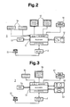
- 1 to 7, 1 denotes an administration center which has a central processor 1.1, a mass storage 1.2, a working memory 1.3, at least one keyboard 1.4 for inputting information and at least one data display device 1.5 and at least one printer 1.6 for outputting information.
- the administration center 1 is connected via modem 2 and telephone connection 2.1 via a public telephone network 4 to at least one regional center 3.
- the indices used in FIG. 1 mean the following from left to right: region, building, process. As an example of this, 1.
- M. I means: Process I in building M of region 1.
- the regional center 3 with A central processor 3.1, a floppy disk station 3.2, a disk storage 3.3, a data storage 3.4 and the peripheral devices such as keyboard 3.5, data display device 3.6, alarm printer 3.7 differ only slightly from the construction of the administration center 1. In terms of size, they differ from the administration center 1 wide EDP applications must be sufficient, the regional center 3, however, is essentially intended for the instruction of service personnel.
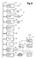
- a telealarm device 5 is used together with a commercially available personal computer 6, which is equipped with a conventional visual display device 6.2 and a keyboard 6.3.
- the building control center 6 is connected to the communication module 7 via the interface 7.4.
- a dialing unit 7.5 distinguishes incoming or outgoing data from incoming or outgoing calls of the telealarm 5.
- a bus module 8 takes over the frequency conversion of the outgoing or incoming data or calls in a modulator 8.1 and a demodulator 8.2 and sends them or receives them via a line coupler 8.3 to or from the building bus 9.
- a peripheral module 10 points a peripheral computer 10.1, a data memory 10.2, a peripheral program memory 10.3 and a timer 10.4.
- the peripheral module 10 is connected to the bus module 8 via a serial interface 10.5.
- a further serial interface 10.6 enables service personnel to communicate locally with the peripheral module 10.
- For data acquisition and data output he has at least one binary input 10.7, at least one binary output 10.8, at least one analog input 10.9 and at least one analog output 10.10.
- a common peripheral bus 10.11 is available within the peripheral module 10.
- the data generated by a process and the commands required for the process 11 are acquired by means of at least one binary data point 11.1, by means of at least one binary function 11.2, by means of at least one analog data point 11.3 and by means of at least one analog function 11.4, or are forwarded to the process 11.
- a network bus 14 is an embodiment variant of the building bus 9 shown in FIG. 1.
- the above-mentioned on-site communication is made possible by connecting a maintenance case 15 to the interface 10.6.
- the voltage / frequency diagram shown in FIG. 7 shows at 16 a data channel width with a data carrier frequency 17.
- a carrier frequency amplitude 20 applies to the speech channel 12 as well as to the data channel 13.
- the system for remote administration of elevator systems shown in FIG. 1 can be divided hierarchically and functionally into four levels: administration level, regional level, building level and process level.
- the modular structure of the system allows the individual levels to be largely independent. Each subordinate level can also function without its superordinate level. Without the administrative center 1, the system still works as a remote inspection system. Without regional center 3, the trunk system remains fully functional as an inspection system for the processes connected across the building. Without building control center 6, each individual process 11 can be monitored by means of peripherals 10 and maintenance case 15.
- the administrative center 1 has the task of centrally and commercially efficiently managing the business required by the maintenance of elevator systems in several regions. For this purpose, it is connected via modem 2 and telephone network 4 to the regional centers 3 of the geographical regions 1 to K.
- the relevant for the administration Data are excreted from the regional centers 32 and transmitted to the administrative center 1 with the aid of known means and methods of data communication.
- the following IT applications are essentially implemented in the administrative center 1 equipped with commercially available devices: - Settlements - cost analysis - Maintenance optimization - Maintenance interval calculations - vulnerability analysis - trend analysis - Management of modernization businesses. The necessary working methods correspond to the state of EDP practice and are therefore not explained in more detail.
- the regional center 3 serves as an interface between the system and the service personnel responsible for the maintenance of an entire region. It processes data and outputs it to the user in plain text.
- the regional center 3 of the geographic region 1 is connected via the modem 2 and the telephone network 4 to the buildings 1.1 to 1.M.
- the regional center 3 of the geographic region K is correspondingly superior to the buildings K.1 to KM.
- operational, Fault, alarm, danger, maintenance and security messages are recorded by the processes 11 assigned to them.
- the central processor 3.1 controlled by the operating system and user program resident in the disk memory further processes the recorded data for the following purposes: - logging - reliability statistics - efficiency analysis - Deployment planning of the service personnel - Route planning of the service personnel - Spare parts planning - Preventive maintenance planning based on the recorded operating and maintenance data. Data with secondary priority are stored on diskette 3.2 and output to printer 3.7 on demand.
- the system has the ability to transmit audio information.
- the operator of a regional center 3 has the possibility of making direct contact with persons involved in a process 11 on a speech channel which is separated in frequency from the data channel.
- the operator of a house control center or the on-site service technician can claim verbal support in solving system problems from the regional control center 3.
- Sending and receiving means are on the elevator side installed directly in the cabin. This enables people in need to report their predicament directly to the building or regional headquarters.
- the regional center 3 allows an insight into all of its subordinate processes 11. By sending a telegram with control and address data of the peripherals 10 to be selected, the regional center 3 receives direct access to the process data, if required. Normally, however, as mentioned below, the data exchange will take place in the opposite direction.
- the regional center 3 calls a communication module 7 only if a certain time has passed without contact. Function tests can be carried out in individual processes 11 from the regional center 3, and actions to remedy the fault condition can be initiated in the event of a fault. For these reasons, the modem 2 provided must be both self-selecting and self-answering. In addition, it must meet the requirements of telearm 5. With an additional circuit placed in the regional center 3 and not mentioned in the figures, voice connections can be established in a comparable manner with the above-mentioned data channels to the central building 6 or the individual peripherals 10.
- the dialing unit 7.5 separates the data traffic from voice traffic into incoming and outgoing Direction.
- the dialing unit 7.5 divides the telephone network-side information channel into the speech channel 12 and the data channel 13.
- the modem 2 converts the data into a transferable two-frequency signal by means of frequency shift keying. In the incoming direction, it converts the frequency-modulated signals back into computer-compatible one-zero signals.
- a communication module 7 takes over the data traffic between the regional center 3 and the processes 11 to be managed in this building.
- the communication computer 7.1 controlled by an EPROM-resident communication program transmits the process data to the regional center 3 via modem 2 and telephone network 4.
- the communication module serves functionally 7 on the one hand as a data buffer 7.2 between the two asynchronous communication lines telephone network 4 / building bus 9 and on the other hand for controlling communication within the building.
- the communication computer 7.1 takes over the data from the connected processes 11 via the bus module 8 / building bus 9 explained below and stores them in the data buffer 7.2. It is not just a question of data. Every time you contact us With the peripheral modules 10, these are checked by the communication computer 7.1 for malfunctions.
- Messages about disturbed peripheral modules 10 are also stored in the data buffer 7.2 and periodically forwarded to the regional center 3 together with the collected process data.
- the communication module 7 does not decide whether process data is relevant for transmission or not. It merely takes over the above-mentioned data traffic between the on-site periphery 10 and the regional center 3. Process messages are processed exclusively by the peripheral modules 10 into process data relevant to transmission and forwarded to the communication module 7.
- the processes 11 of a building can be inspected from the building control center 6.
- a commercially available personal computer 6.1 is connected to the system via the serial interface 7.4.
- the data pending in the data buffer 7.2 are further processed by the personal computer 6.1 for the following purposes: - Logging of operational, alarm and maintenance data of all processes 11 of a building connected to the system - Realization of simple statistical functions - Output of preventive maintenance reports with first priority.
- the processes 11 (FIG. 1), which are indexed with 1.1.1 to 1.1.N, can be monitored from the building control center 6, for example 1.1, but, as from the regional control center 3, function tests and calls of certain process parameters can also be carried out in individual processes 11.
- Information is exchanged within a building by means of the bus module 8 and the building bus 9 between the communication module 7 and the peripheral modules 10.
- the bus module 8 modulates outgoing speech information on the speech carrier frequency 19 and data information on the data carrier frequency 17.
- Information arriving from the building bus 9 arrives at the input via the line coupler 8.3 of the demodulator 8.2, which returns it to its original position by means of filtering and demodulation and forwards it to the voice or data channel in accordance with the information content.
- the device shown in FIGS. 4 and 6 has a network bus 14 as a variant of the building bus 9.
- a separately routed two-wire cable serves as the building bus 9 instead of the intrinsically-free network bus 14.
- the network bus 14 is a serial bus using the high-voltage electrical installation available throughout the building. It does not require its own line network and enables signals to be fed in or received at any point in the power network that is accessible via sockets. For reasons of telecommunications authority, this means of transmitting information regarding range, transmission power and channel frequencies is restricted depending on the postal regulations.
- the range is normally limited to your own property, the transmission power is in the range of a few milliwatts and the permissible frequency band has to be below the long-wave band.
- Carrier frequency locks are provided on the supply side so that no third-party systems outside the property are disturbed or interference signals from outside influence your own system.
- the exchange of data between transmitters and receivers is based on the acknowledgment principle.
- An active transmitter sends information in the form of telegrams with control, address and data characters. He then expects a receipt from the called recipient telegram. The information transfer is only completed when the active sender has received a valid reply.
- the signals are transmitted or received in synchronism with the network.
- the zero crossing range of the phase voltages not used by the phase gating controls ensures a largely interference-free time window in which digital data can be transmitted.
- the transmission methods mentioned result in data transmission with high reliability and extensive security against external interference.
- the frequency plan shown in Fig. 7 shows a possibility for frequency separation between speech and data channel.
- Carrier frequency amplitude 20 and the upper band limit are subject to postal regulations. Speech and data channel bandwidth and choice of speech carrier frequency 19 and data carrier frequency 17 are released by post.
- Each process 11 has its own autonomous on-site peripheral module 10 which can be adapted to the specific process character.
- the regional center 3 and the peripheral module 10 are equal partners with regard to data exchange.
- anyone can initiate a connection to exchange data.
- the peripheral module 10 is cyclically requested by the communication module 7 to exchange data. In doing so only transmit events from the I / O module 10, ie the I / O module 10 does not transmit any process states for the cyclical requests, but only the status changes that occurred between two cycles.
- the peripheral module 10 passes on unusual system states automatically and without being requested.
- Via at least one binary / analog input 10.7 / 10.9 the peripheral computer 10.7 records the process data present at at least one binary / analog data point 11.1 / 11.3.
- Commands and analog variables are passed on to at least one binary / analog function 11.2 / 11.4 to process 11 by means of at least one binary / analog output 10.8 / 10.10.
- the timer 10.4 supplies the peripheral computer 10.1 with the work cycle for cyclical processing of the user programs loaded in the peripheral program memory 10.3.
- the peripheral computer 10.1 controls the data traffic running over the peripheral bus 10.11. All data sources and data sinks connected to the peripheral bus 10.11 and identified by addresses can send and receive data.
- a first interface 10.5 converts parallel data into serial data, determines its transmission speed and sends it towards the communication module 7.
- a corresponding transmission method applies in the opposite direction.
- a second bidirectional interface 10.6 offers the possibility of connecting a maintenance case 15, which enables on-site operation and query of the peripheral module 10 as well as direct intervention opportunities in the respective process allowed.
- the system-specific information is converted into general information.
- the system-specific information relay XX ON / OFF is converted, for example, into the general door OPEN / CLOSE information.
- the management of elevator systems not only requires information that is supplied by real data points. Values derived from calculations, such as operational, traffic, maintenance parameters, etc., are accessed via virtual data points. Real as well as virtual data points can be linked arithmetically and logically as well as conditions, limit values etc.
- the system components database, knowledge base and reasoning procedure form the intelligence of the peripheral module 10.
- the database includes all information of the data points, facts, parameter sizes, etc. of the ongoing process.
- the knowledge base contains a basic set of hypothetical rules that a qualified operator would use to handle process messages.
- the reasoning procedure links the database with the knowledge base. The rules below Consideration of the database information that plays a role in them. The reasoning procedure reveals new information from existing information based on the judgments, assignments and conclusions made in the knowledge base.
- the inference procedure In the event of failure of, for example, a relay sequence, the inference procedure, based on the current information and on the basis of the rules established in the knowledge base about the failed relay sequence, concludes the relay contact causing the failure. Using the new information obtained from the first inference step and further rules, the search for the cause is continued until, for example, the open safety switch causing the failure is found.
Priority Applications (1)
| Application Number | Priority Date | Filing Date | Title |
|---|---|---|---|
| AT87107703T ATE54650T1 (de) | 1986-07-07 | 1987-05-27 | System zur fernverwaltung von aufzugsanlagen. |
Applications Claiming Priority (2)
| Application Number | Priority Date | Filing Date | Title |
|---|---|---|---|
| CH273686 | 1986-07-07 | ||
| CH2736/86 | 1986-07-07 |
Publications (2)
| Publication Number | Publication Date |
|---|---|
| EP0252266A1 true EP0252266A1 (fr) | 1988-01-13 |
| EP0252266B1 EP0252266B1 (fr) | 1990-07-18 |
Family
ID=4240453
Family Applications (1)
| Application Number | Title | Priority Date | Filing Date |
|---|---|---|---|
| EP87107703A Expired - Lifetime EP0252266B1 (fr) | 1986-07-07 | 1987-05-27 | Système de surveillance à distance d'installation d'ascenseur |
Country Status (15)
| Country | Link |
|---|---|
| US (1) | US4771865A (fr) |
| EP (1) | EP0252266B1 (fr) |
| JP (2) | JPS6327382A (fr) |
| CN (1) | CN1007342B (fr) |
| AT (1) | ATE54650T1 (fr) |
| AU (1) | AU591568B2 (fr) |
| CA (1) | CA1269464A (fr) |
| DE (1) | DE3763766D1 (fr) |
| DK (1) | DK170435B1 (fr) |
| ES (1) | ES2016822B3 (fr) |
| FI (1) | FI84531C (fr) |
| HK (1) | HK64191A (fr) |
| NO (1) | NO170177C (fr) |
| PT (1) | PT85261B (fr) |
| ZA (1) | ZA874924B (fr) |
Cited By (14)
| Publication number | Priority date | Publication date | Assignee | Title |
|---|---|---|---|---|
| EP0391174A1 (fr) * | 1989-04-07 | 1990-10-10 | Technischer Überwachungs-Verein Bayern e.V. | Dispositif et méthode pour détecter des paramètres physiques d'un élévateur |
| EP0390972A1 (fr) * | 1989-04-07 | 1990-10-10 | Technischer Überwachungs-Verein Bayern Sachsen e.V. | Dispositif et méthode pour détecter des paramètres physiques d'un élévateur |
| EP0528187A2 (fr) * | 1991-07-23 | 1993-02-24 | Otis Elevator Company | Communication de parole pour un ascenseur |
| US5345046A (en) * | 1991-07-23 | 1994-09-06 | Otis Elevator Company | Voice communication for elevator |
| WO1998040816A1 (fr) * | 1997-03-12 | 1998-09-17 | Verticore Communications Ltd. | Systemes d'affichage d'informations pour ascenseurs |
| EP1050503A1 (fr) * | 1999-05-03 | 2000-11-08 | Inventio Ag | Système d'aide pour ascenseurs |
| US6269911B1 (en) | 1998-09-17 | 2001-08-07 | Inventio Ag | Elevator installation having a central control in a remote central operation center |
| EP0952502B1 (fr) * | 1998-04-21 | 2004-07-14 | Inventio Ag | Système d'entretien pour ascenseurs, escaliers roulants ou trottoirs roulants |
| EP1464605A1 (fr) | 2003-03-26 | 2004-10-06 | Inventio Ag | Procédé pour gérer un système d'ascenseur ou tapis roulant |
| US7073633B2 (en) | 2002-10-29 | 2006-07-11 | Inventio Ag | Device and method for remote maintenance of an elevator |
| EP1847500A2 (fr) * | 2006-04-20 | 2007-10-24 | Esse-Ti S.r.l. | Alarme d'ascenseur et système de gestion |
| DE102006036251A1 (de) * | 2006-08-03 | 2008-02-07 | TÜV Rheinland Industrie Service GmbH | Seilrutsch / Treibfähigkeits-Indikator |
| CN1789101B (zh) * | 1998-01-20 | 2011-04-20 | 甘尼特人造卫星信息网络公司 | 用在电梯中的信息传播系统 |
| CN108910630A (zh) * | 2018-07-06 | 2018-11-30 | 永大电梯设备(中国)有限公司 | 基于多智能体竞争方式的电梯群控系统及方法 |
Families Citing this family (49)
| Publication number | Priority date | Publication date | Assignee | Title |
|---|---|---|---|---|
| JPH01226678A (ja) * | 1988-03-04 | 1989-09-11 | Hitachi Ltd | エレベーター制御装置 |
| US4898263A (en) * | 1988-09-12 | 1990-02-06 | Montgomery Elevator Company | Elevator self-diagnostic control system |
| JP2695867B2 (ja) * | 1988-10-12 | 1998-01-14 | 株式会社日立製作所 | エレベーター装置 |
| FI89580C (fi) * | 1988-10-25 | 1993-10-25 | Kone Oy | Foerfarande och anordning foer maetning och avstaemning av ett hissystem |
| JPH02138081A (ja) * | 1988-11-19 | 1990-05-28 | Hitachi Ltd | 昇降装置システム |
| US5243382A (en) * | 1990-01-31 | 1993-09-07 | Minolta Camera Kabushiki Kaisha | Image forming apparatus capable of efficient maintenance work |
| JP2821227B2 (ja) * | 1990-03-19 | 1998-11-05 | 株式会社 宮豪 | ビルメンテナンス管理システム |
| US5736694A (en) * | 1992-12-22 | 1998-04-07 | Kone Oy | Method for providing a phone alarm call in an elevator system |
| FI111934B (fi) * | 1992-12-22 | 2003-10-15 | Kone Corp | Hissilaitteiden kauko-ohjausjärjestelmä |
| US5714726A (en) * | 1992-12-22 | 1998-02-03 | Kone Oy | Method for performing an alarm call in an elevator system |
| JP3202396B2 (ja) * | 1993-03-26 | 2001-08-27 | 株式会社日立ビルシステム | エレベータの異常解析データ収集装置 |
| US5398782A (en) * | 1993-11-12 | 1995-03-21 | Otis Elevator Company | Remote monitoring system with variable period communication check |
| US5671158A (en) * | 1995-09-18 | 1997-09-23 | Envirotest Systems Corp. | Apparatus and method for effecting wireless discourse between computer and technician in testing motor vehicle emission control systems |
| KR0167183B1 (ko) * | 1995-09-23 | 1998-12-01 | 이희종 | 엘리베이터의 내구성 평가장치 및 평가방법 |
| JP3378148B2 (ja) * | 1996-07-24 | 2003-02-17 | 三菱電機株式会社 | 遠隔地監視装置 |
| US6215998B1 (en) * | 1997-12-11 | 2001-04-10 | Nortel Networks Limited | Local component-specific console |
| US6353853B1 (en) | 1998-10-26 | 2002-03-05 | Triatek, Inc. | System for management of building automation systems through an HTML client program |
| JP2002003108A (ja) * | 2000-06-20 | 2002-01-09 | Mitsubishi Electric Corp | エレベータ群管理システム |
| ES2167244A1 (es) * | 2000-06-29 | 2002-05-01 | Univ Alcala Henares | Sistema de control de una red de ascensores por internet. |
| JP4406516B2 (ja) | 2001-02-16 | 2010-01-27 | 株式会社日立製作所 | 昇降機の管理装置並びに昇降機システム |
| US20020178243A1 (en) * | 2001-05-15 | 2002-11-28 | Kevin Collins | Apparatus and method for centrally managing network devices |
| US8838475B2 (en) * | 2001-08-28 | 2014-09-16 | Inventio Ag | Apparatus and method for using equipment remote monitoring to generate automated product sales offerings |
| US7539504B2 (en) * | 2001-12-05 | 2009-05-26 | Espre Solutions, Inc. | Wireless telepresence collaboration system |
| US6715586B1 (en) | 2002-04-22 | 2004-04-06 | William A. Shubin | Upgraded elevator control circuit and method dealing with fire danger |
| US8068546B2 (en) * | 2002-08-29 | 2011-11-29 | Riip, Inc. | Method and apparatus for transmitting video signals |
| US8558795B2 (en) * | 2004-03-12 | 2013-10-15 | Riip, Inc. | Switchless KVM network with wireless technology |
| US7606314B2 (en) * | 2002-08-29 | 2009-10-20 | Raritan America, Inc. | Method and apparatus for caching, compressing and transmitting video signals |
| US7684483B2 (en) * | 2002-08-29 | 2010-03-23 | Raritan Americas, Inc. | Method and apparatus for digitizing and compressing remote video signals |
| US7818480B2 (en) * | 2002-08-29 | 2010-10-19 | Raritan Americas, Inc. | Wireless management of remote devices |
| ES2446916T3 (es) * | 2003-03-26 | 2014-03-10 | Inventio Ag | Procedimiento para la gestión de una instalación de ascensor o de escalera mecánica |
| US7853663B2 (en) * | 2004-03-12 | 2010-12-14 | Riip, Inc. | Wireless management system for control of remote devices |
| US7350626B2 (en) * | 2004-10-20 | 2008-04-01 | Otis Elevator Company | Power-on-reset of elevator controllers |
| BRPI0518023A (pt) * | 2004-11-09 | 2008-10-28 | Inventio Ag | processo e dispositivo para manutenção de uma instalação de elevador ou escada rolante |
| US8478884B2 (en) | 2005-09-30 | 2013-07-02 | Riip, Inc. | Wireless remote device management utilizing mesh topology |
| US7699142B1 (en) | 2006-05-12 | 2010-04-20 | Wurtec Elevator Products & Services | Diagnostic system having user defined sequence logic map for a transportation device |
| US8688664B2 (en) * | 2007-06-08 | 2014-04-01 | Captivate, Llc | Updating floor-specific information |
| JP4863521B2 (ja) * | 2008-06-30 | 2012-01-25 | 東芝エレベータ株式会社 | 昇降機の保守管理システム |
| CN102153002A (zh) * | 2011-03-07 | 2011-08-17 | 武汉东菱富士电梯制造有限公司 | 电梯监视系统 |
| EP2766290A4 (fr) * | 2011-10-14 | 2015-06-24 | Otis Elevator Co | Système d'ascenseur ayant une messagerie pour une maintenance automatisée |
| US20160107861A1 (en) * | 2013-06-11 | 2016-04-21 | Otis Elevator Company | Cloud server based control |
| CN103274272B (zh) * | 2013-06-20 | 2015-06-10 | 李天彤 | 一种电梯综合管理系统及电梯综合管理方法 |
| CN105636892B (zh) * | 2013-10-08 | 2018-08-10 | 奥的斯电梯公司 | 电梯控制系统 |
| WO2015132447A1 (fr) * | 2014-03-04 | 2015-09-11 | Kone Corporation | Rapport adaptatif de surveillance à distance |
| CN106414296B (zh) * | 2014-04-14 | 2021-02-12 | 因温特奥股份公司 | 用于运行电梯设备的方法以及根据这种方法工作的电梯控制装置 |
| CN107074483B (zh) * | 2014-10-01 | 2020-10-13 | 通力股份公司 | 电梯布置、方法以及计算机程序产品 |
| KR102036218B1 (ko) * | 2016-04-26 | 2019-10-24 | 미쓰비시덴키 가부시키가이샤 | 엘리베이터 원격 보수 지원 시스템, 및 엘리베이터 원격 보수 지원 방법 |
| US10597254B2 (en) | 2017-03-30 | 2020-03-24 | Otis Elevator Company | Automated conveyance system maintenance |
| US10745244B2 (en) | 2017-04-03 | 2020-08-18 | Otis Elevator Company | Method of automated testing for an elevator safety brake system and elevator brake testing system |
| EP3415454B1 (fr) | 2017-06-14 | 2021-09-22 | KONE Corporation | Compensation de défaillance automatique d'ascenseurs, d'escaliers roulants et de portes automatiques |
Citations (5)
| Publication number | Priority date | Publication date | Assignee | Title |
|---|---|---|---|---|
| GB2025663A (en) * | 1978-07-07 | 1980-01-23 | Hitachi Ltd | Elevator test operation apparatus |
| FR2460571A1 (fr) * | 1979-06-29 | 1981-01-23 | Chancrogne Bernard | Dispositif telephonique de securite pour ascenseur |
| GB2136158A (en) * | 1983-02-22 | 1984-09-12 | Otis Elevator Co | Servicing a software-controlled lift |
| US4512442A (en) * | 1984-03-30 | 1985-04-23 | Westinghouse Electric Corp. | Method and apparatus for improving the servicing of an elevator system |
| EP0148000A1 (fr) * | 1983-12-19 | 1985-07-10 | Otis Elevator Company | Système de surveillance à distance |
Family Cites Families (5)
| Publication number | Priority date | Publication date | Assignee | Title |
|---|---|---|---|---|
| US3973648A (en) * | 1974-09-30 | 1976-08-10 | Westinghouse Electric Corporation | Monitoring system for elevator installation |
| US4418795A (en) * | 1981-07-20 | 1983-12-06 | Westinghouse Electric Corp. | Elevator servicing methods and apparatus |
| JPS58193873A (ja) * | 1982-05-07 | 1983-11-11 | 三菱電機株式会社 | エレベ−タの異常通報装置 |
| JPS6023271A (ja) * | 1983-07-20 | 1985-02-05 | 株式会社日立製作所 | エレベ−タ−保守装置 |
| US4698780A (en) * | 1985-10-08 | 1987-10-06 | Westinghouse Electric Corp. | Method of monitoring an elevator system |
-
1987
- 1987-05-27 DE DE8787107703T patent/DE3763766D1/de not_active Expired - Lifetime
- 1987-05-27 ES ES87107703T patent/ES2016822B3/es not_active Expired - Lifetime
- 1987-05-27 AT AT87107703T patent/ATE54650T1/de not_active IP Right Cessation
- 1987-05-27 EP EP87107703A patent/EP0252266B1/fr not_active Expired - Lifetime
- 1987-06-22 FI FI872771A patent/FI84531C/fi not_active IP Right Cessation
- 1987-07-03 NO NO872792A patent/NO170177C/no not_active IP Right Cessation
- 1987-07-06 PT PT85261A patent/PT85261B/pt not_active IP Right Cessation
- 1987-07-06 CN CN87104634A patent/CN1007342B/zh not_active Expired
- 1987-07-06 AU AU75256/87A patent/AU591568B2/en not_active Expired
- 1987-07-06 DK DK346187A patent/DK170435B1/da not_active IP Right Cessation
- 1987-07-07 JP JP62169587A patent/JPS6327382A/ja active Pending
- 1987-07-07 ZA ZA874924A patent/ZA874924B/xx unknown
- 1987-07-07 CA CA000541490A patent/CA1269464A/fr not_active Expired - Lifetime
- 1987-07-17 US US07/074,631 patent/US4771865A/en not_active Expired - Lifetime
-
1991
- 1991-03-14 JP JP1991014914U patent/JPH0630776Y2/ja not_active Expired - Lifetime
- 1991-08-15 HK HK641/91A patent/HK64191A/xx not_active IP Right Cessation
Patent Citations (5)
| Publication number | Priority date | Publication date | Assignee | Title |
|---|---|---|---|---|
| GB2025663A (en) * | 1978-07-07 | 1980-01-23 | Hitachi Ltd | Elevator test operation apparatus |
| FR2460571A1 (fr) * | 1979-06-29 | 1981-01-23 | Chancrogne Bernard | Dispositif telephonique de securite pour ascenseur |
| GB2136158A (en) * | 1983-02-22 | 1984-09-12 | Otis Elevator Co | Servicing a software-controlled lift |
| EP0148000A1 (fr) * | 1983-12-19 | 1985-07-10 | Otis Elevator Company | Système de surveillance à distance |
| US4512442A (en) * | 1984-03-30 | 1985-04-23 | Westinghouse Electric Corp. | Method and apparatus for improving the servicing of an elevator system |
Cited By (19)
| Publication number | Priority date | Publication date | Assignee | Title |
|---|---|---|---|---|
| EP0390972A1 (fr) * | 1989-04-07 | 1990-10-10 | Technischer Überwachungs-Verein Bayern Sachsen e.V. | Dispositif et méthode pour détecter des paramètres physiques d'un élévateur |
| WO1990011958A1 (fr) * | 1989-04-07 | 1990-10-18 | Technischer Überwachungs-Verein Bayern E.V. | Procede et dispositif pour mesurer des parametres physiques relatifs a un ascenseur |
| US5578801A (en) * | 1989-04-07 | 1996-11-26 | Technischer Uberwachungs-Verein Bayern E.V. | Apparatus and method for sensing slippage of elevator drive cable over a traction sheave |
| EP0391174A1 (fr) * | 1989-04-07 | 1990-10-10 | Technischer Überwachungs-Verein Bayern e.V. | Dispositif et méthode pour détecter des paramètres physiques d'un élévateur |
| EP0528187A2 (fr) * | 1991-07-23 | 1993-02-24 | Otis Elevator Company | Communication de parole pour un ascenseur |
| EP0528187A3 (en) * | 1991-07-23 | 1993-05-12 | Otis Elevator Company | Voice communications for elevator |
| US5345046A (en) * | 1991-07-23 | 1994-09-06 | Otis Elevator Company | Voice communication for elevator |
| CN100436297C (zh) * | 1997-03-12 | 2008-11-26 | 卡普提维特网络公司 | 一种用于电梯的信息显示系统及为该系统提供信息的方法 |
| WO1998040816A1 (fr) * | 1997-03-12 | 1998-09-17 | Verticore Communications Ltd. | Systemes d'affichage d'informations pour ascenseurs |
| CN1789101B (zh) * | 1998-01-20 | 2011-04-20 | 甘尼特人造卫星信息网络公司 | 用在电梯中的信息传播系统 |
| EP0952502B1 (fr) * | 1998-04-21 | 2004-07-14 | Inventio Ag | Système d'entretien pour ascenseurs, escaliers roulants ou trottoirs roulants |
| US6269911B1 (en) | 1998-09-17 | 2001-08-07 | Inventio Ag | Elevator installation having a central control in a remote central operation center |
| EP1050503A1 (fr) * | 1999-05-03 | 2000-11-08 | Inventio Ag | Système d'aide pour ascenseurs |
| US7073633B2 (en) | 2002-10-29 | 2006-07-11 | Inventio Ag | Device and method for remote maintenance of an elevator |
| EP1464605A1 (fr) | 2003-03-26 | 2004-10-06 | Inventio Ag | Procédé pour gérer un système d'ascenseur ou tapis roulant |
| EP1847500A2 (fr) * | 2006-04-20 | 2007-10-24 | Esse-Ti S.r.l. | Alarme d'ascenseur et système de gestion |
| EP1847500A3 (fr) * | 2006-04-20 | 2009-05-20 | Esse-Ti S.r.l. | Alarme d'ascenseur et système de gestion |
| DE102006036251A1 (de) * | 2006-08-03 | 2008-02-07 | TÜV Rheinland Industrie Service GmbH | Seilrutsch / Treibfähigkeits-Indikator |
| CN108910630A (zh) * | 2018-07-06 | 2018-11-30 | 永大电梯设备(中国)有限公司 | 基于多智能体竞争方式的电梯群控系统及方法 |
Also Published As
| Publication number | Publication date |
|---|---|
| CN87104634A (zh) | 1988-01-27 |
| NO872792L (no) | 1988-01-08 |
| JPH0630776Y2 (ja) | 1994-08-17 |
| AU7525687A (en) | 1988-01-14 |
| FI872771A0 (fi) | 1987-06-22 |
| FI84531B (fi) | 1991-08-30 |
| DK346187D0 (da) | 1987-07-06 |
| US4771865A (en) | 1988-09-20 |
| CN1007342B (zh) | 1990-03-28 |
| PT85261B (pt) | 1993-07-30 |
| FI84531C (fi) | 1991-12-10 |
| DK346187A (da) | 1988-01-08 |
| AU591568B2 (en) | 1989-12-07 |
| HK64191A (en) | 1991-08-23 |
| JPS6327382A (ja) | 1988-02-05 |
| NO170177B (no) | 1992-06-09 |
| NO170177C (no) | 1992-09-16 |
| DE3763766D1 (de) | 1990-08-23 |
| DK170435B1 (da) | 1995-09-04 |
| CA1269464A (fr) | 1990-05-22 |
| EP0252266B1 (fr) | 1990-07-18 |
| PT85261A (pt) | 1988-07-29 |
| JPH0496474U (fr) | 1992-08-20 |
| NO872792D0 (no) | 1987-07-03 |
| ZA874924B (en) | 1988-05-25 |
| ATE54650T1 (de) | 1990-08-15 |
| ES2016822B3 (es) | 1990-12-01 |
| FI872771A (fi) | 1988-01-08 |
Similar Documents
| Publication | Publication Date | Title |
|---|---|---|
| EP0252266B1 (fr) | Système de surveillance à distance d'installation d'ascenseur | |
| DE69534587T2 (de) | Abtaster von Verbindungsmöglichkeiten | |
| EP0973342B1 (fr) | Procédé et système de communication pour le traitement d'alarmes par un réseau de gestion comportant plusieurs niveaux de gestion | |
| DE69926519T2 (de) | Strukturierungssystem zur überwachung und steuerung der ausrüstung einer anlage | |
| EP0192120B1 (fr) | Système et dispositif de transmission de données pour commande à distance | |
| DE4231816C2 (de) | Diagnose- und Überwachungsverfahren für Türen und Tore | |
| EP0993714A2 (fr) | Procede et systeme pour commander l'utilisation de la capacite de transmission de satellites dans des reseaux terrestres | |
| DE3514334A1 (de) | Gebaeude-steuersystem | |
| EP1286497A1 (fr) | Procédé pour la représentation graphique de l' état de noeuds de réseau dans un réseau surveillé, et système de surveillance et module de programme associé | |
| DE60216629T2 (de) | Gibt es kein spezifisches kontrollmodul? benutzen sie eines das weniger spezifisch ist | |
| DE102004048394B4 (de) | Fernsteuerungssystem | |
| DE19519879A1 (de) | Verfahren sowie Anordnung zur Sicherung und Überwachung von Objekten mit Hilfe vorhandener Rechnernetze, bzw. autonomer Rechnersysteme | |
| WO1999022491A1 (fr) | Dispositif de raccordement des elements reseau d'une installation de telecommunications a un reseau de gestion des telecommunications | |
| EP1102167B1 (fr) | Mise en place et opération d'une connection avec une unité de commande | |
| DE10024487B4 (de) | Verfahren und Vorrichtung zur Fernwartung, -überwachung und/oder -bedienung von in Notrufanlagen gruppierten Notrufendgeräten | |
| DE10026648B4 (de) | Verfahren zur Fernwartung, -überwachung und/ oder -bedienung von in Notrufanlagen gruppierten Notrufendgeräten | |
| DE102005054099B4 (de) | Mobiles Überwachungssystem | |
| EP0974215A2 (fr) | Liaison de communication de donnees dans un reseau de communication hierarchique a bus, fonctionnant selon un protocole demande/reponse, a savoir selon le "protocole d'appel selectif" | |
| DE2823918A1 (de) | Schaltungsanordnung zur zentralen stoerungssignalisierung in betriebsstellen | |
| EP0412320A1 (fr) | Méthode de transmission de données au moyen de télégrammes d'impulsions entre des postes d'abonnés d'un dispositif de télétraitement et circuit pour mettre en oeuvre la méthode | |
| WO1994002999A1 (fr) | Dispositif de surveillance d'un dispositif de transmission de messages | |
| EP1052607A1 (fr) | Procédé et dispositif pour paramètrer un système de sécurité | |
| DE3610726A1 (de) | Ueberwachungssystem fuer leitungsnetze | |
| Hilton | Commercial Telephone Centralization/Consolidation Strategies for Military Applications | |
| EP0687097A2 (fr) | Arrangement pour une centrale de commande des interventions |
Legal Events
| Date | Code | Title | Description |
|---|---|---|---|
| PUAI | Public reference made under article 153(3) epc to a published international application that has entered the european phase |
Free format text: ORIGINAL CODE: 0009012 |
|
| AK | Designated contracting states |
Kind code of ref document: A1 Designated state(s): AT BE CH DE ES FR GB IT LI LU NL SE |
|
| 17P | Request for examination filed |
Effective date: 19880613 |
|
| 17Q | First examination report despatched |
Effective date: 19890629 |
|
| GRAA | (expected) grant |
Free format text: ORIGINAL CODE: 0009210 |
|
| AK | Designated contracting states |
Kind code of ref document: B1 Designated state(s): AT BE CH DE ES FR GB IT LI LU NL SE |
|
| REF | Corresponds to: |
Ref document number: 54650 Country of ref document: AT Date of ref document: 19900815 Kind code of ref document: T |
|
| REF | Corresponds to: |
Ref document number: 3763766 Country of ref document: DE Date of ref document: 19900823 |
|
| GBT | Gb: translation of ep patent filed (gb section 77(6)(a)/1977) | ||
| ET | Fr: translation filed | ||
| ITF | It: translation for a ep patent filed |
Owner name: MODIANO & ASSOCIATI S.R.L. |
|
| PLBE | No opposition filed within time limit |
Free format text: ORIGINAL CODE: 0009261 |
|
| STAA | Information on the status of an ep patent application or granted ep patent |
Free format text: STATUS: NO OPPOSITION FILED WITHIN TIME LIMIT |
|
| ITTA | It: last paid annual fee | ||
| 26N | No opposition filed | ||
| EPTA | Lu: last paid annual fee | ||
| EAL | Se: european patent in force in sweden |
Ref document number: 87107703.8 |
|
| REG | Reference to a national code |
Ref country code: GB Ref legal event code: IF02 |
|
| PGFP | Annual fee paid to national office [announced via postgrant information from national office to epo] |
Ref country code: SE Payment date: 20060512 Year of fee payment: 20 |
|
| PGFP | Annual fee paid to national office [announced via postgrant information from national office to epo] |
Ref country code: NL Payment date: 20060515 Year of fee payment: 20 Ref country code: AT Payment date: 20060515 Year of fee payment: 20 |
|
| PGFP | Annual fee paid to national office [announced via postgrant information from national office to epo] |
Ref country code: LU Payment date: 20060517 Year of fee payment: 20 |
|
| PGFP | Annual fee paid to national office [announced via postgrant information from national office to epo] |
Ref country code: FR Payment date: 20060519 Year of fee payment: 20 Ref country code: DE Payment date: 20060519 Year of fee payment: 20 |
|
| PGFP | Annual fee paid to national office [announced via postgrant information from national office to epo] |
Ref country code: GB Payment date: 20060522 Year of fee payment: 20 |
|
| PGFP | Annual fee paid to national office [announced via postgrant information from national office to epo] |
Ref country code: ES Payment date: 20060530 Year of fee payment: 20 |
|
| PGFP | Annual fee paid to national office [announced via postgrant information from national office to epo] |
Ref country code: IT Payment date: 20060531 Year of fee payment: 20 |
|
| PGFP | Annual fee paid to national office [announced via postgrant information from national office to epo] |
Ref country code: BE Payment date: 20060616 Year of fee payment: 20 |
|
| PGFP | Annual fee paid to national office [announced via postgrant information from national office to epo] |
Ref country code: CH Payment date: 20060818 Year of fee payment: 20 |
|
| PG25 | Lapsed in a contracting state [announced via postgrant information from national office to epo] |
Ref country code: NL Free format text: LAPSE BECAUSE OF EXPIRATION OF PROTECTION Effective date: 20070527 |
|
| PG25 | Lapsed in a contracting state [announced via postgrant information from national office to epo] |
Ref country code: ES Free format text: LAPSE BECAUSE OF EXPIRATION OF PROTECTION Effective date: 20070528 |
|
| REG | Reference to a national code |
Ref country code: GB Ref legal event code: PE20 |
|
| REG | Reference to a national code |
Ref country code: CH Ref legal event code: PL |
|
| EUG | Se: european patent has lapsed | ||
| NLV7 | Nl: ceased due to reaching the maximum lifetime of a patent |
Effective date: 20070527 |
|
| REG | Reference to a national code |
Ref country code: ES Ref legal event code: FD2A Effective date: 20070528 |
|
| PG25 | Lapsed in a contracting state [announced via postgrant information from national office to epo] |
Ref country code: GB Free format text: LAPSE BECAUSE OF EXPIRATION OF PROTECTION Effective date: 20070526 |
|
| BE20 | Be: patent expired |
Owner name: *INVENTIO A.G. Effective date: 20070527 |