EP1286497A1 - Procédé pour la représentation graphique de l' état de noeuds de réseau dans un réseau surveillé, et système de surveillance et module de programme associé - Google Patents
Procédé pour la représentation graphique de l' état de noeuds de réseau dans un réseau surveillé, et système de surveillance et module de programme associé Download PDFInfo
- Publication number
- EP1286497A1 EP1286497A1 EP01440243A EP01440243A EP1286497A1 EP 1286497 A1 EP1286497 A1 EP 1286497A1 EP 01440243 A EP01440243 A EP 01440243A EP 01440243 A EP01440243 A EP 01440243A EP 1286497 A1 EP1286497 A1 EP 1286497A1
- Authority
- EP
- European Patent Office
- Prior art keywords
- network
- network element
- messages
- trend
- screen
- Prior art date
- Legal status (The legal status is an assumption and is not a legal conclusion. Google has not performed a legal analysis and makes no representation as to the accuracy of the status listed.)
- Granted
Links
Images
Classifications
-
- H—ELECTRICITY
- H04—ELECTRIC COMMUNICATION TECHNIQUE
- H04L—TRANSMISSION OF DIGITAL INFORMATION, e.g. TELEGRAPHIC COMMUNICATION
- H04L41/00—Arrangements for maintenance, administration or management of data switching networks, e.g. of packet switching networks
- H04L41/22—Arrangements for maintenance, administration or management of data switching networks, e.g. of packet switching networks comprising specially adapted graphical user interfaces [GUI]
-
- H—ELECTRICITY
- H04—ELECTRIC COMMUNICATION TECHNIQUE
- H04L—TRANSMISSION OF DIGITAL INFORMATION, e.g. TELEGRAPHIC COMMUNICATION
- H04L41/00—Arrangements for maintenance, administration or management of data switching networks, e.g. of packet switching networks
- H04L41/06—Management of faults, events, alarms or notifications
- H04L41/0604—Management of faults, events, alarms or notifications using filtering, e.g. reduction of information by using priority, element types, position or time
- H04L41/0609—Management of faults, events, alarms or notifications using filtering, e.g. reduction of information by using priority, element types, position or time based on severity or priority
-
- H—ELECTRICITY
- H04—ELECTRIC COMMUNICATION TECHNIQUE
- H04L—TRANSMISSION OF DIGITAL INFORMATION, e.g. TELEGRAPHIC COMMUNICATION
- H04L41/00—Arrangements for maintenance, administration or management of data switching networks, e.g. of packet switching networks
- H04L41/06—Management of faults, events, alarms or notifications
- H04L41/0604—Management of faults, events, alarms or notifications using filtering, e.g. reduction of information by using priority, element types, position or time
- H04L41/0622—Management of faults, events, alarms or notifications using filtering, e.g. reduction of information by using priority, element types, position or time based on time
-
- H—ELECTRICITY
- H04—ELECTRIC COMMUNICATION TECHNIQUE
- H04Q—SELECTING
- H04Q3/00—Selecting arrangements
- H04Q3/0016—Arrangements providing connection between exchanges
- H04Q3/0062—Provisions for network management
Definitions
- the invention relates to a method for the visual representation of states of network elements of a network to be monitored in one Monitoring device according to the preamble of claim 1, and a monitoring device and program module for this.
- Alarm management For monitoring and controlling a communication network with a A large number of network elements are now central monitoring procedures used with standardized messages. An essential part of this Monitoring procedures concern alarm management. To the Alarm management is part of the collection of all alarm messages Objects of the monitored network or subnetwork, the determination of Alarm conditions and the visual representation of the messages and Alarm conditions.
- the alarm messages and are from the International Telecommunication Unit (ITU) entitled Recommendation X.733 "Information Technology - Open System Interconnection - System Management: Alarm Reporting Function "standardized, in the following briefly ITU guideline X.733 called.
- ITU International Telecommunication Unit
- Alarm types, Alarm causes, alarm severity levels or Urgency levels and various alarm displays, for example a trend display and a threshold value display (English: threshold information) defined. To display the trend, it is determined whether the urgency of a currently detected alarm is higher or lower is the urgency of all alarms that have been determined (and still current) so far.
- a communication network is monitored depending on its size this network from one or more central monitoring stations. Efficient monitoring with the lowest possible personnel expenditure requires the monitoring device to be concentrated as much as possible few monitoring points. This means that a monitoring body for monitoring a variety of network devices, for example is responsible for more than 50 exchanges.
- the efficiency a surveillance agency depends to a large extent on the User interface, i.e. the visual representation of alarm messages and alarm states and the trend display of alarm states.
- Network elements are represented by connecting lines. Due to the complex network of relationships, only a very limited one Number of network elements can be displayed in one screen window. In order to be able to represent each of these network elements when required, this is Network divided into several sub-networks or sub-graphics, one in upper display level, these subnetworks each as an image object are displayed and only when you select or click on one Picture element a corresponding sub-graphic with the contained therein Network elements is shown.
- Another window shows, for example, in a scrollable (to scroll) List all incoming alarm messages in their chronological order.
- the alarm messages received can also be checked filter certain criteria. For example, it is possible only To display alarm messages from a certain severity.
- the operator must monitor the alarm status of the network elements frequently switch between the views described above. to Assessment of the dynamic development of alarm conditions, i.e. to Trend forecast, it is also necessary to update current alarm numbers with earlier compare the number of alarms shown.
- the invention has for its object a method for compact Representation of the status of facilities in a network with as much as possible comprehensive status information and the information about its execution to create necessary funds.
- this object is achieved by a method according to the teaching of claim 1, a monitoring device according to the teaching of Claim 5 and a program module according to the teaching of claim 6 solved.
- the basic idea of the invention is based on incoming messages Network element or for a network element a current state from a Set of possible states for the network elements of a monitored Network to determine the number of pending messages a Determine network element at certain times, and a to determine current state trend, all network elements or selected Represent network elements as image objects on a screen, where each image object at least that for the corresponding network element shows the determined current status and status trend.
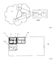
- FIG. 1 shows a communication network N with three interconnected Network elements NE1, NE2 and NE3 and a network monitoring device NMC, which a processing unit PRU and an associated Representation unit DIU.
- the network elements NE1, NE2 and NE3 are each represented by dashed lines with the Processing unit PRU connected. These dashed lines symbolize a management network or Administrative connections through which alarm messages and messages the network elements NE1, NE2 and NE3 to the network monitoring device NMC are transmitted.
- the network elements NE1, NE2 and NE3 represent communication nodes of the Communication network N, in particular switching centers.
- the ITU guideline X.733 mentioned above defines this for everyone Alarm message including the parameters event time, event type and Event information.
- the event time is the time of the alarm occurrence or the Alarm generation in the network element.
- the event type categorizes the alarm occurred. It can be, for example Communication alarm, a quality of service alarm Service), device error alarm, processing error alarm or Act environmental alarm.
- the event information includes a detailed predefined information about the possible cause of the Alarm. Possible causes of a communication alarm can be for example, a call establishment error error) or a loss of signal. to Event information also includes urgency information. Doing so evaluates how big the effects on the respective network element are.
- Monitoring device NMC received alarm messages in of different forms and, if necessary, by means of hierarchically oriented ones Display levels as a (screen) window on a screen visualized on the display unit DIU.
- a window with a network graphic for an overview is offered, in which the individual network elements NE1, NE2 and NE3 of the to be monitored Communication network N as small picture objects or so-called "icons" being represented.
- the picture objects have a name, for example Symbol for the type of network element, a numeric Display of incoming pending alarms and depending on the current one Urgency, i.e. after the most urgent alarm still pending can take defined alarm colors.
- the relationships of Network elements are represented by connecting lines.
- Another window shows, for example, in a scrollable (to scroll) List all incoming alarm messages in their chronological order on.
- the alarm messages received can be displayed filtered by the operator according to different defined criteria. That's the way it is for example possible, only alarm messages from a certain one Display severity or certain alarm messages only then display when a certain number of similar alarm messages has been received.
- Such alarm messages can also optionally be used suppressed which have already been completed, i.e. which by the operator were acknowledged as done or for which in the corresponding network element it was determined that the cause of the alarm no longer exists and a corresponding alarm message in the monitoring device NMC received.
- the ITU guideline X.733 defined above a trend indication for the development of the Urgency of alarms.
- many network elements represent complex ones Devices with multiple sub-elements or objects, where each of these objects sends out alarm messages independently. Since the Determination of the trend display mentioned in the network element NE1, NE2 or NE3 takes place and as a parameter to the network monitoring device NMC such a trend display can therefore only ever be transmitted get the respective object.
- the Trend display takes three possible states: depending on whether the highest reported urgency level of a current time interval compared to the highest level of urgency reported earlier interval is higher, equal or lower, the Trend display the status "increasing urgency", "no change” or "decreasing urgency”.
- this trend display has the disadvantage that it makes no statement about contains the trend of the number of pending pending alarm messages and only on an object of a network element NE1, NE2 or NE3 refers.
- NE1, NE2 or NE3 refers.
- Often all incoming alarm messages indicate an object the same level of urgency. For example, an object becomes a Exchange, which is close to its capacity limit, increased Report alarm messages about failed connection attempts. With increasing utilization of the exchange come in increasingly Similar messages of shorter intervals.
- the state of the art according to such alarm messages solve, despite increasing frequency a neutral trend display.
- a state trend is formed which shows how the number of pending alarm messages and thus the status of one Network element NE1, NE2 or NE3 developed.
- a Status trend only for alarm messages with certain criteria, for example for pending alarm messages for a specific Urgency level or from a certain urgency level.
- On unfinished alarm message is an alarm message whose the cause of the alarm has not yet been remedied and therefore not yet Completion notification, i.e. one complementary to the alarm message Message that has been received.
- the completion message can be from corresponding network element NE1, NE2 or NE3 come or through Input of the operating personnel in the network monitoring device NMC (not all network elements can carry out notification themselves initiate). It is also conceivable that if there is no completion report the completion of an alarm after a certain period of time Is accepted.
- Time intervals This is done at certain times, preferably in the same length Time intervals, entered in the network monitoring device and alarms not yet resolved.
- This length of the time intervals can be predefined or configurable. In the simplest case, it shows State trend 3 states on: increasing number, constant number and decreasing number. Alternatively, the state trend can be more than three Accept values, for example between a slight increase and sharp increase or slight decrease and sharp decrease further is distinguished.
- FIG. 2 shows a screen surface or image display DI on a Screen of the display unit DIU of an inventive Monitoring device with three image objects O1, O2 and O3, which the network elements NE1, NE2 and NE3 of Represent communication network N from Fig.1.
- the picture objects are in Formed a tightly packed matrix.
- Each picture object shows a certain color, here hatched as black, white or black symbolizes, and three display fields 11, 12 and 13.
- the first Display field 11 labeled NAME provides a name field Identification of the respective network element.
- the second display field 12 with the inscription N represents a number field. In this number field you can for example the sum of all current or not completed critical or urgent alarm messages of the respective network element are displayed.
- the third display field shows an arrow in a circle, which is a trend depending on the direction.
- the exemplary in The first image object O1 horizontally represented arrow represents a neutral one Trend for the first network element NE1
- the example in the second Image object O2 from bottom left to top right represents an arrow positive trend for the second network element NE2
- the example in the third image object O3 from top left to bottom right arrow represents a negative trend.
- one image object O1, O2 or O3 exactly one network element NE1, NE2 or NE3, for example one Switching center, a so-called gateway, a so-called router or represents a service computer.
- network elements for example the network elements of one regional subnet can be represented as an image object.
- the color of this The picture object then corresponds to the color of each of its network elements, which one has the most critical condition.
- the state trend then shows the trend exactly the sum of the alarms and thus the overall condition of all affected network elements.
- the method according to the invention allows due to the dense arrangement of network elements NE1, NE2 and NE3, each with integrated Trend state a highly compressed and at the same time meaningful information about states and dynamic Condition development of an extensive network. An operator can thus largely dispense with other images as long as it is in Development discovered no abnormalities here. Only when, for example a network element in a critical state also a positive one Trend condition, the operator needs to get more detailed Information on a view with complete alarm messages about this Change network element.
- the display can be set to selected network elements are restricted according to certain criteria. So can be defined as a selection criterion, for example, that only Elements from a certain urgency level and with neutral or positive status trend are displayed.
- the content of at least one current message especially the content of the last message received, one Network element NE1, NE2 or NE3 displayed on request.
- This Information can also be in a speech bubble Message windows (a so-called "bubble aid") appear when the screen cursor is moved to a corresponding image object.
- a summary trend information of each Network elements NE1, NE2 and NE3 represents a detailed Trend information, e.g. the number of alarms per severity, the number new / deleted alarms in the last interval or the status trend each Object of a network element, displayed on the DI screen when requested become.
- the request can be just as in the previous sections for a (detailed) representation of messages described by means of a Message window take place.
Priority Applications (4)
| Application Number | Priority Date | Filing Date | Title |
|---|---|---|---|
| EP01440243A EP1286497B1 (fr) | 2001-07-30 | 2001-07-30 | Procédé pour la représentation graphique de l' état de noeuds de réseau dans un réseau surveillé, et système de surveillance et module de programme associé |
| AT01440243T ATE281725T1 (de) | 2001-07-30 | 2001-07-30 | Verfahren zur visuellen darstellung von zuständen von netzelementen eines zu überwachenden netzwerks, sowie eine überwachungseinrichtung und ein programmmodul hierfür |
| DE50104402T DE50104402D1 (de) | 2001-07-30 | 2001-07-30 | Verfahren zur visuellen Darstellung von Zuständen von Netzelementen eines zu überwachenden Netzwerks, sowie eine Überwachungseinrichtung und ein Programmmodul hierfür |
| US10/200,501 US7111241B2 (en) | 2001-07-30 | 2002-07-23 | Method for the visual display of states of network elements of a network to be monitored, and also a monitoring device and program module therefor |
Applications Claiming Priority (1)
| Application Number | Priority Date | Filing Date | Title |
|---|---|---|---|
| EP01440243A EP1286497B1 (fr) | 2001-07-30 | 2001-07-30 | Procédé pour la représentation graphique de l' état de noeuds de réseau dans un réseau surveillé, et système de surveillance et module de programme associé |
Publications (2)
| Publication Number | Publication Date |
|---|---|
| EP1286497A1 true EP1286497A1 (fr) | 2003-02-26 |
| EP1286497B1 EP1286497B1 (fr) | 2004-11-03 |
Family
ID=8183270
Family Applications (1)
| Application Number | Title | Priority Date | Filing Date |
|---|---|---|---|
| EP01440243A Expired - Lifetime EP1286497B1 (fr) | 2001-07-30 | 2001-07-30 | Procédé pour la représentation graphique de l' état de noeuds de réseau dans un réseau surveillé, et système de surveillance et module de programme associé |
Country Status (4)
| Country | Link |
|---|---|
| US (1) | US7111241B2 (fr) |
| EP (1) | EP1286497B1 (fr) |
| AT (1) | ATE281725T1 (fr) |
| DE (1) | DE50104402D1 (fr) |
Cited By (3)
| Publication number | Priority date | Publication date | Assignee | Title |
|---|---|---|---|---|
| DE102004045023A1 (de) * | 2004-09-15 | 2006-03-30 | Siemens Ag | Verfahren zum Betreiben einer automatisierten Produktionsanlage, Computerprogramm-Produkt und computerlesbares Medium |
| CN102932173A (zh) * | 2012-10-24 | 2013-02-13 | 华为技术有限公司 | 一种显示网络状态的方法和设备 |
| CN113419483A (zh) * | 2021-07-06 | 2021-09-21 | 乐聚(深圳)机器人技术有限公司 | 设备状态的显示方法、装置、终端及存储介质 |
Families Citing this family (8)
| Publication number | Priority date | Publication date | Assignee | Title |
|---|---|---|---|---|
| WO2004049173A1 (fr) * | 2002-11-28 | 2004-06-10 | Allied Telesis K.K. | Systeme de gestion d'appareil et son procede |
| US20060075503A1 (en) * | 2004-09-13 | 2006-04-06 | Achilles Guard, Inc. Dba Critical Watch | Method and system for applying security vulnerability management process to an organization |
| CA3077184C (fr) | 2008-05-21 | 2021-05-18 | Dwight Tays | Procede et systeme d'inspection de voies ferrees |
| US8601117B2 (en) * | 2008-12-23 | 2013-12-03 | Telefonaktiebolaget L M Ericsson (Publ) | Subscribing to and distributing summary of faults in three-tiered network monitoring architecture |
| US9916068B1 (en) * | 2013-03-13 | 2018-03-13 | Ca, Inc. | Graphical user interface for displaying alarm security level of groups of elements |
| TWI502475B (zh) * | 2014-05-26 | 2015-10-01 | Senao Networks Inc | Visual network debugging method |
| US20160182274A1 (en) * | 2014-12-17 | 2016-06-23 | Alcatel-Lucent Canada Inc. | System and method of prioritizing alarms within a network or data center |
| US9729386B2 (en) | 2014-12-17 | 2017-08-08 | Alcatel Lucent | System and method of visualizing most unhealthy network elements within a network or data center |
Citations (1)
| Publication number | Priority date | Publication date | Assignee | Title |
|---|---|---|---|---|
| US6112015A (en) * | 1996-12-06 | 2000-08-29 | Northern Telecom Limited | Network management graphical user interface |
Family Cites Families (4)
| Publication number | Priority date | Publication date | Assignee | Title |
|---|---|---|---|---|
| US6664978B1 (en) * | 1997-11-17 | 2003-12-16 | Fujitsu Limited | Client-server computer network management architecture |
| AU5448500A (en) * | 1999-05-26 | 2000-12-28 | Alok Batra | Network element management system |
| US20020046299A1 (en) * | 2000-02-09 | 2002-04-18 | Internet2Anywhere, Ltd. | Method and system for location independent and platform independent network signaling and action initiating |
| US7237243B2 (en) * | 2001-06-11 | 2007-06-26 | Microsoft Corporation | Multiple device management method and system |
-
2001
- 2001-07-30 EP EP01440243A patent/EP1286497B1/fr not_active Expired - Lifetime
- 2001-07-30 AT AT01440243T patent/ATE281725T1/de not_active IP Right Cessation
- 2001-07-30 DE DE50104402T patent/DE50104402D1/de not_active Expired - Lifetime
-
2002
- 2002-07-23 US US10/200,501 patent/US7111241B2/en not_active Expired - Lifetime
Patent Citations (1)
| Publication number | Priority date | Publication date | Assignee | Title |
|---|---|---|---|---|
| US6112015A (en) * | 1996-12-06 | 2000-08-29 | Northern Telecom Limited | Network management graphical user interface |
Cited By (3)
| Publication number | Priority date | Publication date | Assignee | Title |
|---|---|---|---|---|
| DE102004045023A1 (de) * | 2004-09-15 | 2006-03-30 | Siemens Ag | Verfahren zum Betreiben einer automatisierten Produktionsanlage, Computerprogramm-Produkt und computerlesbares Medium |
| CN102932173A (zh) * | 2012-10-24 | 2013-02-13 | 华为技术有限公司 | 一种显示网络状态的方法和设备 |
| CN113419483A (zh) * | 2021-07-06 | 2021-09-21 | 乐聚(深圳)机器人技术有限公司 | 设备状态的显示方法、装置、终端及存储介质 |
Also Published As
| Publication number | Publication date |
|---|---|
| US20030046386A1 (en) | 2003-03-06 |
| US7111241B2 (en) | 2006-09-19 |
| DE50104402D1 (de) | 2004-12-09 |
| ATE281725T1 (de) | 2004-11-15 |
| EP1286497B1 (fr) | 2004-11-03 |
Similar Documents
| Publication | Publication Date | Title |
|---|---|---|
| EP0973342B1 (fr) | Procédé et système de communication pour le traitement d'alarmes par un réseau de gestion comportant plusieurs niveaux de gestion | |
| EP1096348B1 (fr) | Intégration d'un appareil de commande sur site dans un système de commande d'une installation | |
| DE60213154T2 (de) | Verfahren und System zur Erzeugung geographisch-visueller Anzeigen von Breitband - Netzwerkdaten | |
| DE69726005T2 (de) | Graphische benutzerschnittstelle zur netzwerkverwaltung | |
| WO1999008420A1 (fr) | Dispositif de commande permettant de commander un systeme de gestion reseau | |
| EP1286497B1 (fr) | Procédé pour la représentation graphique de l' état de noeuds de réseau dans un réseau surveillé, et système de surveillance et module de programme associé | |
| EP0252266A1 (fr) | Système de surveillance à distance d'installation d'ascenseur | |
| EP0632617A2 (fr) | Procédé et appareil pour le support du management de réseau | |
| WO2010130343A2 (fr) | Système de gestion d'alarme | |
| DE60300393T2 (de) | OSPF Monitor | |
| DE10251911A1 (de) | Verfahren für das Konfigurationsmanagement, Netzwerk und überwachte Komponente | |
| WO2004008784A1 (fr) | Identification d'insuffisances de rendement en matiere de services dans un reseau de communication | |
| EP1206883B1 (fr) | Procede d'alignement generique dans un environnement a plusieurs gestionnaires | |
| DE60224775T2 (de) | Netzwerkverwaltungssystem basierend auf Tendenzanalyse | |
| EP1286498A1 (fr) | Méthode, agent et système de gestion de réseau pour le fonctionnement d'un réseau de télécommunication | |
| EP1437859A1 (fr) | Procédé pour le traitement des alarmes par un réseau de gestion à plusieurs couches dans un système de communication | |
| EP0797330B1 (fr) | Réseau d'ordinateurs et méthode de gestion correspondante | |
| EP1582030B1 (fr) | Procede de traitement d'alarmes par un reseau de gestion a plusieurs niveaux de systeme de communication | |
| WO1999022491A1 (fr) | Dispositif de raccordement des elements reseau d'une installation de telecommunications a un reseau de gestion des telecommunications | |
| EP1371236B1 (fr) | Procede de reacheminement selectif et collectif de messages dans un reseau de gestion de telecommunications | |
| DE19717112C2 (de) | Verfahren und Wartungsanlage zum Betreiben eines Telekommunikationsnetzes | |
| DE10337464A1 (de) | Verfahren zur Behandlung von Alarmen in einem Managementsystem eines Kommunikationsnetzes | |
| EP1195946A2 (fr) | Procédé pour la mise à disposition de services dans un système de gestion de réseau avec architecture ouverte et avec des objets de service, des objets de requête et un gestionnaire de requêtes | |
| DE102008045238A1 (de) | Verfahren zur Inbetriebnahme eines Systems zur Ermittelung der Energieflüsse in einer Energieverteilungseinrichtung | |
| EP1096349A1 (fr) | Configuration pour un dispositif de commande d'une installation |
Legal Events
| Date | Code | Title | Description |
|---|---|---|---|
| PUAI | Public reference made under article 153(3) epc to a published international application that has entered the european phase |
Free format text: ORIGINAL CODE: 0009012 |
|
| 17P | Request for examination filed |
Effective date: 20020515 |
|
| AK | Designated contracting states |
Kind code of ref document: A1 Designated state(s): AT BE CH CY DE DK ES FI FR GB GR IE IT LI LU MC NL PT SE TR |
|
| AX | Request for extension of the european patent |
Extension state: AL LT LV MK RO SI |
|
| AKX | Designation fees paid |
Designated state(s): AT BE CH CY DE DK ES FI FR GB GR IE IT LI LU MC NL PT SE TR |
|
| GRAP | Despatch of communication of intention to grant a patent |
Free format text: ORIGINAL CODE: EPIDOSNIGR1 |
|
| GRAS | Grant fee paid |
Free format text: ORIGINAL CODE: EPIDOSNIGR3 |
|
| GRAA | (expected) grant |
Free format text: ORIGINAL CODE: 0009210 |
|
| AK | Designated contracting states |
Kind code of ref document: B1 Designated state(s): AT BE CH CY DE DK ES FI FR GB GR IE IT LI LU MC NL PT SE TR |
|
| PG25 | Lapsed in a contracting state [announced via postgrant information from national office to epo] |
Ref country code: TR Free format text: LAPSE BECAUSE OF FAILURE TO SUBMIT A TRANSLATION OF THE DESCRIPTION OR TO PAY THE FEE WITHIN THE PRESCRIBED TIME-LIMIT Effective date: 20041103 Ref country code: IE Free format text: LAPSE BECAUSE OF FAILURE TO SUBMIT A TRANSLATION OF THE DESCRIPTION OR TO PAY THE FEE WITHIN THE PRESCRIBED TIME-LIMIT Effective date: 20041103 Ref country code: NL Free format text: LAPSE BECAUSE OF FAILURE TO SUBMIT A TRANSLATION OF THE DESCRIPTION OR TO PAY THE FEE WITHIN THE PRESCRIBED TIME-LIMIT Effective date: 20041103 Ref country code: FI Free format text: LAPSE BECAUSE OF FAILURE TO SUBMIT A TRANSLATION OF THE DESCRIPTION OR TO PAY THE FEE WITHIN THE PRESCRIBED TIME-LIMIT Effective date: 20041103 |
|
| REG | Reference to a national code |
Ref country code: GB Ref legal event code: FG4D Free format text: NOT ENGLISH |
|
| REG | Reference to a national code |
Ref country code: CH Ref legal event code: EP |
|
| GBT | Gb: translation of ep patent filed (gb section 77(6)(a)/1977) | ||
| REF | Corresponds to: |
Ref document number: 50104402 Country of ref document: DE Date of ref document: 20041209 Kind code of ref document: P |
|
| REG | Reference to a national code |
Ref country code: IE Ref legal event code: FG4D Free format text: GERMAN |
|
| PG25 | Lapsed in a contracting state [announced via postgrant information from national office to epo] |
Ref country code: GR Free format text: LAPSE BECAUSE OF FAILURE TO SUBMIT A TRANSLATION OF THE DESCRIPTION OR TO PAY THE FEE WITHIN THE PRESCRIBED TIME-LIMIT Effective date: 20050203 Ref country code: DK Free format text: LAPSE BECAUSE OF FAILURE TO SUBMIT A TRANSLATION OF THE DESCRIPTION OR TO PAY THE FEE WITHIN THE PRESCRIBED TIME-LIMIT Effective date: 20050203 Ref country code: SE Free format text: LAPSE BECAUSE OF FAILURE TO SUBMIT A TRANSLATION OF THE DESCRIPTION OR TO PAY THE FEE WITHIN THE PRESCRIBED TIME-LIMIT Effective date: 20050203 |
|
| PG25 | Lapsed in a contracting state [announced via postgrant information from national office to epo] |
Ref country code: ES Free format text: LAPSE BECAUSE OF FAILURE TO SUBMIT A TRANSLATION OF THE DESCRIPTION OR TO PAY THE FEE WITHIN THE PRESCRIBED TIME-LIMIT Effective date: 20050214 |
|
| NLV1 | Nl: lapsed or annulled due to failure to fulfill the requirements of art. 29p and 29m of the patents act | ||
| REG | Reference to a national code |
Ref country code: IE Ref legal event code: FD4D |
|
| PG25 | Lapsed in a contracting state [announced via postgrant information from national office to epo] |
Ref country code: CY Free format text: LAPSE BECAUSE OF FAILURE TO SUBMIT A TRANSLATION OF THE DESCRIPTION OR TO PAY THE FEE WITHIN THE PRESCRIBED TIME-LIMIT Effective date: 20050730 Ref country code: AT Free format text: LAPSE BECAUSE OF NON-PAYMENT OF DUE FEES Effective date: 20050730 Ref country code: LU Free format text: LAPSE BECAUSE OF NON-PAYMENT OF DUE FEES Effective date: 20050730 |
|
| PG25 | Lapsed in a contracting state [announced via postgrant information from national office to epo] |
Ref country code: LI Free format text: LAPSE BECAUSE OF NON-PAYMENT OF DUE FEES Effective date: 20050731 Ref country code: BE Free format text: LAPSE BECAUSE OF NON-PAYMENT OF DUE FEES Effective date: 20050731 Ref country code: CH Free format text: LAPSE BECAUSE OF NON-PAYMENT OF DUE FEES Effective date: 20050731 Ref country code: MC Free format text: LAPSE BECAUSE OF NON-PAYMENT OF DUE FEES Effective date: 20050731 |
|
| PLBE | No opposition filed within time limit |
Free format text: ORIGINAL CODE: 0009261 |
|
| STAA | Information on the status of an ep patent application or granted ep patent |
Free format text: STATUS: NO OPPOSITION FILED WITHIN TIME LIMIT |
|
| ET | Fr: translation filed | ||
| 26N | No opposition filed |
Effective date: 20050804 |
|
| REG | Reference to a national code |
Ref country code: CH Ref legal event code: PL |
|
| BERE | Be: lapsed |
Owner name: *ALCATEL Effective date: 20050731 |
|
| PG25 | Lapsed in a contracting state [announced via postgrant information from national office to epo] |
Ref country code: PT Free format text: LAPSE BECAUSE OF NON-PAYMENT OF DUE FEES Effective date: 20050403 |
|
| REG | Reference to a national code |
Ref country code: GB Ref legal event code: 732E Free format text: REGISTERED BETWEEN 20131114 AND 20131120 |
|
| REG | Reference to a national code |
Ref country code: FR Ref legal event code: GC Effective date: 20140717 |
|
| REG | Reference to a national code |
Ref country code: FR Ref legal event code: RG Effective date: 20141016 |
|
| REG | Reference to a national code |
Ref country code: FR Ref legal event code: PLFP Year of fee payment: 15 |
|
| REG | Reference to a national code |
Ref country code: FR Ref legal event code: PLFP Year of fee payment: 16 |
|
| REG | Reference to a national code |
Ref country code: FR Ref legal event code: PLFP Year of fee payment: 17 |
|
| REG | Reference to a national code |
Ref country code: FR Ref legal event code: PLFP Year of fee payment: 18 |
|
| PGFP | Annual fee paid to national office [announced via postgrant information from national office to epo] |
Ref country code: DE Payment date: 20180723 Year of fee payment: 18 Ref country code: IT Payment date: 20180724 Year of fee payment: 18 Ref country code: FR Payment date: 20180725 Year of fee payment: 18 |
|
| PGFP | Annual fee paid to national office [announced via postgrant information from national office to epo] |
Ref country code: GB Payment date: 20180719 Year of fee payment: 18 |
|
| REG | Reference to a national code |
Ref country code: DE Ref legal event code: R119 Ref document number: 50104402 Country of ref document: DE |
|
| GBPC | Gb: european patent ceased through non-payment of renewal fee |
Effective date: 20190730 |
|
| PG25 | Lapsed in a contracting state [announced via postgrant information from national office to epo] |
Ref country code: GB Free format text: LAPSE BECAUSE OF NON-PAYMENT OF DUE FEES Effective date: 20190730 Ref country code: DE Free format text: LAPSE BECAUSE OF NON-PAYMENT OF DUE FEES Effective date: 20200201 |
|
| PG25 | Lapsed in a contracting state [announced via postgrant information from national office to epo] |
Ref country code: FR Free format text: LAPSE BECAUSE OF NON-PAYMENT OF DUE FEES Effective date: 20190731 |
|
| PG25 | Lapsed in a contracting state [announced via postgrant information from national office to epo] |
Ref country code: IT Free format text: LAPSE BECAUSE OF NON-PAYMENT OF DUE FEES Effective date: 20190730 |