EP0391174A1 - Dispositif et méthode pour détecter des paramètres physiques d'un élévateur - Google Patents
Dispositif et méthode pour détecter des paramètres physiques d'un élévateur Download PDFInfo
- Publication number
- EP0391174A1 EP0391174A1 EP90105566A EP90105566A EP0391174A1 EP 0391174 A1 EP0391174 A1 EP 0391174A1 EP 90105566 A EP90105566 A EP 90105566A EP 90105566 A EP90105566 A EP 90105566A EP 0391174 A1 EP0391174 A1 EP 0391174A1
- Authority
- EP
- European Patent Office
- Prior art keywords
- traction sheave
- evaluation unit
- cable
- elevator
- control circuit
- Prior art date
- Legal status (The legal status is an assumption and is not a legal conclusion. Google has not performed a legal analysis and makes no representation as to the accuracy of the status listed.)
- Granted
Links
Images


Classifications
-
- B—PERFORMING OPERATIONS; TRANSPORTING
- B66—HOISTING; LIFTING; HAULING
- B66B—ELEVATORS; ESCALATORS OR MOVING WALKWAYS
- B66B5/00—Applications of checking, fault-correcting, or safety devices in elevators
- B66B5/0006—Monitoring devices or performance analysers
- B66B5/0037—Performance analysers
-
- B—PERFORMING OPERATIONS; TRANSPORTING
- B66—HOISTING; LIFTING; HAULING
- B66B—ELEVATORS; ESCALATORS OR MOVING WALKWAYS
- B66B1/00—Control systems of elevators in general
- B66B1/24—Control systems with regulation, i.e. with retroactive action, for influencing travelling speed, acceleration, or deceleration
- B66B1/28—Control systems with regulation, i.e. with retroactive action, for influencing travelling speed, acceleration, or deceleration electrical
-
- B—PERFORMING OPERATIONS; TRANSPORTING
- B66—HOISTING; LIFTING; HAULING
- B66B—ELEVATORS; ESCALATORS OR MOVING WALKWAYS
- B66B5/00—Applications of checking, fault-correcting, or safety devices in elevators
- B66B5/0006—Monitoring devices or performance analysers
Definitions
- the innovation relates to a device for detecting physical parameters, in particular movement parameters, of a goods and / or passenger elevator, the elevator having at least one cable pull guided over a traction sheave, at one end of which the car and at the other end of which a counterweight hangs , is driven by a drive motor controlled by an electrical control circuit and operates on the drive pulley, and comprises a brake device connected to the drive pulley and controlled by the control circuit.
- the background for this innovation is safety checks on goods and passenger lifts. Such lifts must be subjected to regular checks, e.g. Characteristic values such as travel paths, braking distances, catching paths and the slip resistance (driving ability) of the cable pull driven by the traction sheave must be determined.
- this object is achieved in that an evaluation unit with a timer is provided, and in that a distance sensor connected to the cable pull and / or the traction sheave is provided, which is connected to an input of the evaluation unit, and that the evaluation unit further, with Switching points of the control circuit, at which signals controlling the movement sequence of the elevator are present, have connectable inputs.
- kinematic data of the elevators that is to say travel path and associated time measurement values, can be determined as a function of the signals controlling the movement sequence of the elevator, the required test characteristic values being able to be determined from the kinematic data.
- the new test procedure represents a significant improvement from a safety point of view in that the elevator is not subjected to high loads during the test.
- the evaluation unit can advantageously have a device for determining and recording distance, speed and acceleration values as a function of time or distance.
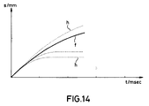
- the braking and catching curves recorded in this way are combined into one Screen or printer output and overlaid with calculated envelopes (which define permissible upper and lower limits). This makes it easy to determine the effectiveness of the brake and safety gear.
- the determined curves can be saved on a data carrier.
- the evaluation device expediently comprises a computer, preferably a personal computer.
- the device according to the innovation has a force measuring signal transmitter connected to the cable, by means of which the forces transmitted by the cable and determining the sequence of movements of the car can be determined.
- a force measuring signal transmitter connected to the cable, by means of which the forces transmitted by the cable and determining the sequence of movements of the car can be determined.
- An advantageous development of the invention consists in a method for acquiring physical parameters.
- the rope, the car and the counterweight are accelerated or decelerated in a targeted manner during normal elevator operation.
- the movement parameters of the rope and the traction sheave are recorded separately depending on the time.
- the movement parameters of the rope and traction sheave are compared with a predetermined limit movement parameter (for example a limit curve), the drive capacity of the traction sheave being fulfilled in any case when this limit value is exceeded.
- a predetermined limit movement parameter for example a limit curve
- the reference numeral 1 denotes a traction sheave which has two guide grooves for a cable pull 2 formed in the present case by two cables.
- a car 3 is attached to one end of the cable 2.
- a counterweight 4 hangs at the other end of the cable 2.
- the mass of the counterweight 4 usually corresponds to the mass of the car 3 plus half the permissible car load.
- 5 designates a motor-transmission-brake unit for driving the traction sheave 1, this unit having a handwheel 10 for rotating the traction sheave 1.
- the unit 5 contains a brake for the traction sheave 1.
- the unit 5 with the traction sheave 1 is arranged above a ceiling 11 which closes off the elevator shaft.
- the car 3 When driving, the car 3 is moved via the cable 2, which is driven by the motor-transmission-brake unit via the traction sheave 1.
- the cable For the elevator system to work properly, it is necessary that the cable is laid over the traction sheave in a non-slip manner.
- the car can also be moved by the handwheel 10 in the event of an emergency, repairs or checks.
- 6 denotes an evaluation unit, which in the present exemplary embodiment comprises a personal computer 12, an input / output interface 13 and an interface module 14. With the dashed outline 6 'is intended to indicate that the input / output interface 13 and Interface module 14 form a functional unit.
- the personal computer has a screen 36 as a display device and an input keyboard 37. Between the individual components of the evaluation unit, data traffic takes place in both directions in accordance with the arrows that connect the components.
- the evaluation unit 6 is in each case via one of the lines 15 to 17 with a first distance transducer 7, which can be motionally connected with a cable of the cable pull 2, a second distance transducer 18, which can be motionally connected with the traction sheave 1, for example by contact, and connected to a force measuring signal generator 8, the lines being connected to the evaluation unit via inputs provided on the interface module.
- 9 designates lines via which the evaluation unit is connected to the control circuit 46 of the elevator system.
- the lines 9, like the lines 15 to 17, are connected to inputs which are provided on the interface module 14.
- the lines 9 are combined to form a 12-wire shielded cable which has a test plug which can be connected to the control circuit 46 of the elevator system at one end and a circuit board plug with a voltage protection circuit at the other end.
- the interface module 14 comprises four modules. For electrical signals that are transmitted from the control circuit 46 via the lines 9 to the evaluation unit, a control subinterface is provided, which has an optocoupler for each input for electrical isolation of the evaluation unit from the control circuit. has an operational amplifier for signal amplification to be operated with only one operating voltage, provided with a capacitive feedback, and a Schmitt trigger. A largely symmetrical sensor sub-interface is provided for recording and preprocessing signals from the distance sensors and the force measuring signal transmitter. As a third module, the interface module 14 has a divider module for dividing the system clock of the personal computer 12. Finally, the interface module contains an acoustic signal transmitter which has a monoflop with a pulse width of approximately 500 ms and a downstream piezo beeper.
- the input / output interface has a decoder, an input / output and a timer module.
- the timer module contains a universally programmable counter, the clock input of which is connected to the system clock of the personal computer via the divider module of the interface module.
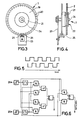
- the distance sensor has a perforated disk 19 with light passage holes 20 arranged concentrically around the pivot point of the perforated disk at equal intervals.
- the perforated disk is concentrically connected to a drive disk 21 provided with a guide slot for a driving cable rope.
- the perforated disk 19 with the drive disk 21 has an axis of rotation 24 which is rotatably mounted in a holder 23.
- At 25 is a first and at 26 is a second Designated light barrier measuring device whose light rays can pass through the perforated disk or can be interrupted by the perforated disk.
- the distance between the two light barriers and the distance between the light passage holes on the perforated disk is selected so that when the perforated disk rotates in one direction for the signals of the two light barrier devices, the pulse diagrams shown in FIG. 5 with temporally offset pulses result.
- the direction of rotation can be determined by evaluating the measurement signals emitted by both light barriers. Such an evaluation circuit is shown in FIG. 6. In addition to path impulses, the number of which is characteristic of the travel path of the car, the circuit also supplies a signal indicating the direction of movement of the car.
- Fig. 12 shows an embodiment of a double-path transducer which combines the two transducers 7 and 18 in one unit.
- the two distance transducers are slidably mounted against each other and can be pressed with the tread 45 both against the traction sheave and with the running groove 22 'against a supporting cable.
- the mode of operation of the individual distance sensors corresponds to the sensor in FIGS. 3 and 4.
- the force transducer has a helical compression spring 28 guided in a guide sleeve 27, which can be compressed by a pull rod 29, which has a disc 30 at one end against which the spring 28 comes into contact and an eyelet 31 at the other end is.
- 32 with a distance transducer is designated by which a displacement of the pull rod 29 against the guide sleeve 27 can be detected and thus a measurement signal for the force acting on the pull rod can be supplied.
- the distance sensor 32 is shown separately in FIG. 8. 3 and 4, it has a perforated disk 19 'and two light barrier measuring devices 25' and 26 '.
- the perforated disc 19 ' is connected via an axis of rotation 24' to a drive wheel 33 which comes against the tie rod 29 and is driven by the tie rod.
- FIG. 9 another embodiment of a force transducer 8 is shown, which differs from the embodiment of FIG. 7 in that a distance transducer for detecting the displacement of the pull rod 29 'against the guide sleeve 27' is provided, one with the Drawbar 29 'connected, movable against the guide sleeve perforated strip 35 with equidistantly arranged in a line light passage holes 20'.
- a first light barrier device 25 ⁇ and a second light barrier device 26 ⁇ are provided to scan the through holes 20 '.
- the connection of the force transducer 8 with the cable 2 and its support on the ceiling 11 is analogous to Fig.7.
- the direction of movement of the drawbar can be determined.
- FIG. 10 shows a further embodiment for a dynamometer 8, which corresponds in terms of arrangement to the embodiment according to FIG. 7 and differs from it in that the force between the point of application 34 and the elongated holes of the belt attachment 37 is not direct acts on the spring, but is deflected via the joint 35 and presses on the support balls 36 on the plate springs 38.
- the plate springs 38 are guided through a sleeve 39 on the outside.
- the transducer holder 40 serves to hold the distance sensor (dial gauge) 50 according to FIG. 11.
- the distance sensor dial gauge
- it has a perforated disk 19 and two light barrier measuring devices 26.
- the perforated disk 19 is driven by the rack 42 via the gear 43.
- a return spring serves to eliminate the play between gear 43 and rack 42.
- this distance transducer can be fixed to the transducer receptacle 40 of the dynamometer FIG. 10 and there it senses the spring travel, translated by the lever ratio joint 35 - support ball 36 - transducer receptacle 40.
- measurements of travel distances, speeds and accelerations of the car as a function of time or of the path can be carried out as a function of the signals of the control circuit of the elevator system that control the movement of the car carried out and recorded.
- These curves can be output on the computer screen or on a printer. By comparing with the target curves, statements can be made about the effectiveness of the brake and safety gear.
- FIG. 13 shows a typical course of a path (s) over time (t) curve (f) as it was recorded during a catching process. As shown in FIG. 13, this curve (f) is output on the screen or on the printer.
- Two consecutive braking distance measurements can be used to calculate the braking distance of the car loaded with nominal load in the direction from. It is also possible to calculate the braking deceleration when the car is loaded with 1.5 times the nominal load. This is possible because these different braking distances (sleer from to sleer up) are caused by known mass differences. All other masses involved (including rotary) are equally involved in both experiments and can therefore be eliminated. Speeds can also be determined, since the respective times are also stored in a table in the computer for the corresponding routes. Two braking attempts with an empty car can therefore be used to calculate the braking distance or braking deceleration for any load. It is therefore possible to make a statement about the brake under load from the empty car.
- the slip resistance (driving ability) of the cable can also be determined. 7 or 9 or 10 with one or more cables 2 of the cable pull with the aid of a suitable cable clamp 49.
- the guide sleeve of the force transducer is fastened to a fixed point via a belt strap 47 and a cross member 48, expediently on the ceiling 11 closing the elevator shaft.
- the tensile force must be increased in the slip test until either a determined limit value is reached and the signal generator emits a warning signal, or the rope or the ropes on the traction sheave begin to slide.
- the onset of slides can visually e.g. B. by shifting applied markings or by evaluating the signals of the first with the cable and the second with the traction sheave connectable distance sensor.
- the driving ability can also be determined in the following manner with the device described:
- the two distance sensors are each motion-connected with the traction sheave and a suspension cable.
- the control line 9 is connected accordingly to the elevator control.
- the elevator is now out decelerated at full speed with maximum braking effect. From the time the delay is divided, the travel sensors record the distances traveled, which are stored in the computer with the associated times in a table. By evaluating these tables, it can then be determined whether or how far the suspension cable has slid over the traction sheave. Furthermore, it can be determined at which delay the static friction has overcome and the slipping has started and at which delay the ropes have stopped again relative to the traction sheave (transition from sliding friction to static friction). Since the delayed masses (ropes, car and counterweight) are known or can be determined, the delays can therefore be extrapolated directly to the corresponding forces. It can also be determined from which load the elevator slips and at which load there is static friction again.
- both position transducers In order to be able to record path differences, both position transducers must either emit the same impulses for the same distances or be synchronized with a correction factor.
- the two odometers are automatically calibrated with each measuring process. This is achieved as follows: At the beginning of the braking process, before the brake is applied, the elevator moves at an almost constant speed. No additional forces act between the suspension cable and traction sheave. Both odometers travel the same route. If the number of pulses of the two travel meters is now put in relation to each other, this quotient is the synchronization factor of the two travel meters. This synchronization is implemented using software, for example.
- the device described is also able to check the control circuit of the elevator by checking the chronological sequence of the control signals. E.g. the time it takes for the control to switch off the drive or to apply a brake after a safety switch has been opened can be determined.
- the evaluation unit has a number of functional devices, some of which are implemented as software solutions.
- a functional device is provided for determining the speed and / or acceleration values.
- the measurement of the speed can be triggered by actuating the keyboard or it is triggered by signals from the control circuit of the elevator. Measurement results can be displayed on the screen of the personal computer and, if necessary, can be output as a complete test report on a printer.
- the acoustic signal transmitter contained in the interface module 14 can be activated.
- the screen can also be used to display instructions for operating the device.
- the sensor interface causes the computer when an external event occurs, e.g. Advance the perforated disc to interrupt its work and update the corresponding internal memory for distance and possibly time.
- an external event e.g. Advance the perforated disc to interrupt its work and update the corresponding internal memory for distance and possibly time.
- timers and acoustic signal generators with the necessary control were accommodated in the sensor interface.
- dispensing with these modules and instead, controlled by software, using the corresponding modules in the computer.
- the device and the method according to the invention enable the travel movement of an elevator to be recorded very precisely with regard to the distance covered and the associated time. Accelerations and decelerations can be recorded in a very fine time grid.
- Accelerations and decelerations can be recorded in a very fine time grid.
- the empty car can be braked during the upward travel, with an operator holding a distance sensor 7 against the running suspension cable before and during the deceleration.
- the fact whether or not the suspension cable slips on the traction sheave can be visually assessed in this case by marking the position of the suspension cable on the traction sheave with a line before the deceleration.
- the empty elevator car is either accelerated or decelerated.
- the brake of the elevator is held in the standby position by a brake magnet that is constantly energized. If the power supply to the brake magnet is interrupted for the test procedure, the brake starts. The intended interruption of the current supply for the magnet can be used as a trigger for starting the measuring process.
- the short period between the interruption of the power supply and the subsequent intervention of the brake can be used to synchronize the distance sensors for the traction sheave and for the rope. During this short period of time there is a constant speed in both parts. During this period, the two distance meters assigned to the support cable and the traction sheave are synchronized by setting the number of counts of the one distance meter in comparison to that of the second knife. The factor determined in this way is used to convert counting pulses from both sensors into sections. Any manufacturing tolerances between the two odometers as well as different wear and tear are automatically eliminated.
Applications Claiming Priority (2)
| Application Number | Priority Date | Filing Date | Title |
|---|---|---|---|
| DE8904375U DE8904375U1 (fr) | 1989-04-07 | 1989-04-07 | |
| DE8904375U | 1989-04-07 |
Publications (3)
| Publication Number | Publication Date |
|---|---|
| EP0391174A1 true EP0391174A1 (fr) | 1990-10-10 |
| EP0391174B1 EP0391174B1 (fr) | 1992-01-29 |
| EP0391174B2 EP0391174B2 (fr) | 1997-10-15 |
Family
ID=6838048
Family Applications (1)
| Application Number | Title | Priority Date | Filing Date |
|---|---|---|---|
| EP90105566A Expired - Lifetime EP0391174B2 (fr) | 1989-04-07 | 1990-03-23 | Dispositif et méthode pour détecter des paramètres physiques d'un élévateur |
Country Status (9)
| Country | Link |
|---|---|
| US (1) | US5578801A (fr) |
| EP (1) | EP0391174B2 (fr) |
| JP (2) | JPH04506502A (fr) |
| AT (1) | ATE72203T1 (fr) |
| DE (2) | DE8904375U1 (fr) |
| DK (1) | DK0391174T3 (fr) |
| ES (1) | ES2029929T5 (fr) |
| GR (2) | GR3004164T3 (fr) |
| WO (1) | WO1990011958A1 (fr) |
Cited By (2)
| Publication number | Priority date | Publication date | Assignee | Title |
|---|---|---|---|---|
| EP1832541A1 (fr) * | 2006-03-08 | 2007-09-12 | TÜV Rheinland Industrie Service GmbH | Rabot de vérification doté d'un appui |
| CN112875454A (zh) * | 2021-01-20 | 2021-06-01 | 中国电子产品可靠性与环境试验研究所((工业和信息化部电子第五研究所)(中国赛宝实验室)) | 电梯打滑检测方法 |
Families Citing this family (32)
| Publication number | Priority date | Publication date | Assignee | Title |
|---|---|---|---|---|
| DE9015495U1 (fr) * | 1990-11-12 | 1992-01-02 | Technischer Ueberwachungs-Verein Bayern E.V., 8000 Muenchen, De | |
| JP3491905B2 (ja) * | 1992-03-02 | 2004-02-03 | 株式会社日立ビルシステム | エレベータの制動性監視装置 |
| DE4217587C2 (de) * | 1992-05-21 | 1999-02-25 | Ernst Dipl Ing Kasten | Anlagen-Diagnoseverfahren |
| JPH09110326A (ja) * | 1995-07-31 | 1997-04-28 | Otis Elevator Co | エレベータかごの制御方法およびエレベータの制御機構 |
| FR2782689B1 (fr) * | 1998-05-18 | 2002-08-23 | Alsthom Gec | Bogie de vehicule ferroviaire, procede d'usinage de ce bogie et outil pour la mise en oeuvre de ce procede |
| AU2001248207B2 (en) * | 2000-04-27 | 2005-08-18 | Inventio Ag | Device for producing elevator shaft information |
| US6325179B1 (en) * | 2000-07-19 | 2001-12-04 | Otis Elevator Company | Determining elevator brake, traction and related performance parameters |
| FI118684B (fi) * | 2004-01-09 | 2008-02-15 | Kone Corp | Menetelmä ja järjestelmä hissin jarrujen kunnon testaamiseksi |
| US7578373B2 (en) * | 2004-05-28 | 2009-08-25 | Mitsubishi Denki Kabushiki Kaisha | Elevator rope slip detector and elevator system |
| US7428951B2 (en) * | 2004-08-19 | 2008-09-30 | Mitsubishi Denki Kabushiki Kaisha | Brake device for elevator |
| FI119877B (fi) * | 2005-08-19 | 2009-04-30 | Kone Corp | Hissin turvajärjestely |
| DE102006011093A1 (de) * | 2006-03-08 | 2007-09-13 | TÜV Rheinland Industrie Service GmbH | Seilschlupf-Detektor |
| DE102006011395B4 (de) * | 2006-03-09 | 2014-12-31 | TÜV Rheinland Industrie Service GmbH | Messvorrichtung für eine Treibfähigkeitsmessung |
| DE102006042909B4 (de) * | 2006-03-28 | 2011-05-26 | Tsg Technische Service Gesellschaft Mbh | Dynamische Bestimmung der Treibfähigkeit bei Treibscheiben-getriebenen Aufzugsanlagen |
| DE102006036251A1 (de) * | 2006-08-03 | 2008-02-07 | TÜV Rheinland Industrie Service GmbH | Seilrutsch / Treibfähigkeits-Indikator |
| DE102007009602A1 (de) | 2007-02-26 | 2008-08-28 | TÜV Rheinland Industrie Service GmbH | Treibfähigkeitsmessung an Treibscheibenaufzugsanlagen |
| US8210319B2 (en) * | 2007-08-31 | 2012-07-03 | John W. Boyd | Hydraulic elevating platform assembly |
| EP2213606B1 (fr) * | 2008-02-08 | 2018-04-25 | Mitsubishi Electric Corporation | Dispositif d'ascenseur |
| DE102009026992A1 (de) * | 2009-06-17 | 2010-12-30 | Dekra Testing & Inspection Gmbh | Vorrichtung und Verfahren zur Prüfung der ordnungsgemäßen Funktionsfähigkeit eines Aufzugs |
| DE102009028596A1 (de) * | 2009-08-17 | 2011-03-03 | Dekra Testing & Inspection Gmbh | Verfahren und Anordnung zur Prüfung der ordnungsgemäßen Funktionsfähigkeit eines Aufzugs |
| DE102011076241A1 (de) | 2011-03-07 | 2012-09-13 | Dekra Industrial Gmbh | Verfahren und Vorrichtung zur Prüfung der ordnungsgemäßen Funktionsfähigkeit eines Aufzugs |
| JP5823196B2 (ja) * | 2011-07-14 | 2015-11-25 | 東芝エレベータ株式会社 | トラクション能力試験装置 |
| FI123348B (fi) * | 2011-10-07 | 2013-02-28 | Kone Corp | Hissin valvontajärjestely sekä menetelmä hissin valvomiseksi |
| CN104685762B (zh) | 2012-09-05 | 2018-06-26 | 通力股份公司 | 一种用于固定到机器的轴向磁通电机以及将轴向磁通电机固定到机器的方法 |
| EP2774886B1 (fr) * | 2013-03-04 | 2015-11-18 | Kone Corporation | Élévateur avec poulie de traction |
| EP2883826B1 (fr) * | 2013-12-16 | 2018-07-04 | Inventio AG | Frein d'ascenseur |
| ES2602062T3 (es) * | 2014-05-19 | 2017-02-17 | Kone Corporation | Un ascensor |
| ES2692202T3 (es) * | 2015-05-20 | 2018-11-30 | Kone Corporation | Ascensor que comprende una disposición de supervisión de cables para detectar un desplazamiento de cables con forma de correa |
| US10745244B2 (en) * | 2017-04-03 | 2020-08-18 | Otis Elevator Company | Method of automated testing for an elevator safety brake system and elevator brake testing system |
| US11198586B2 (en) * | 2019-07-03 | 2021-12-14 | Otis Elevator Company | Braking deceleration measurement of an elevator system |
| CN110282518B (zh) * | 2019-07-15 | 2020-10-16 | 福建省特种设备检验研究院 | 一种电梯制停距离的检测方法 |
| CN112141844A (zh) * | 2020-09-09 | 2020-12-29 | 通辽市特种设备检验所 | 一种用于老旧电梯安全评估的综合检测系统 |
Citations (8)
| Publication number | Priority date | Publication date | Assignee | Title |
|---|---|---|---|---|
| US3773146A (en) * | 1972-05-09 | 1973-11-20 | Reliance Electric Co | Elevator electronic position device |
| US3781901A (en) * | 1972-03-14 | 1973-12-25 | E Morrison | Method for evaluating elevator performance |
| US4085823A (en) * | 1975-11-03 | 1978-04-25 | Westinghouse Electric Corporation | Elevator system |
| GB2136158A (en) * | 1983-02-22 | 1984-09-12 | Otis Elevator Co | Servicing a software-controlled lift |
| EP0192513A1 (fr) * | 1985-02-12 | 1986-08-27 | Societe Logilift S.A.R.L. | Procédé de commande régulée d'un moteur électrique pour le déplacement d'un mobile et dispositif de commande pour la mise en oeuvre du procédé |
| US4698780A (en) * | 1985-10-08 | 1987-10-06 | Westinghouse Electric Corp. | Method of monitoring an elevator system |
| EP0252266A1 (fr) * | 1986-07-07 | 1988-01-13 | Inventio Ag | Système de surveillance à distance d'installation d'ascenseur |
| DE3822466A1 (de) * | 1987-07-21 | 1989-02-02 | Univ Magdeburg Tech | Verfahren zur kontrolle von lage und bewegung seilbewegter transporteinrichtungen |
Family Cites Families (10)
| Publication number | Priority date | Publication date | Assignee | Title |
|---|---|---|---|---|
| JPS58167373A (ja) * | 1982-03-29 | 1983-10-03 | 三菱電機株式会社 | エレベ−タの移動距離検出装置 |
| SU1253928A1 (ru) * | 1983-09-14 | 1986-08-30 | Всесоюзный Научно-Исследовательский Институт Горной Механики Им.М.М.Федорова | Устройство дл исключени скольжени канатов по шкивам трени шахтной подъемной установки |
| DE3713271A1 (de) * | 1987-04-18 | 1988-11-03 | Siemens Ag | Verfahren und einrichtung zur wegregelung eines positionsantriebes |
| DE3864091D1 (de) * | 1987-06-30 | 1991-09-12 | Inventio Ag | Istwertgeber fuer den lageregelkreis eines aufzugsantriebes. |
| FI84050C (fi) * | 1988-04-18 | 1991-10-10 | Kone Oy | Foerfarande foer kontroll av friktionen mellan drivskiva och baerlinor till en hiss. |
| US4833380A (en) * | 1988-07-01 | 1989-05-23 | Magee John E | Hoist motor protection |
| FI89580C (fi) * | 1988-10-25 | 1993-10-25 | Kone Oy | Foerfarande och anordning foer maetning och avstaemning av ett hissystem |
| US4936419A (en) * | 1988-10-26 | 1990-06-26 | Montgomery Elevator Co. | Elevator diagnostic display system |
| DE3911391C5 (de) * | 1989-04-07 | 2010-04-29 | TÜV SÜD Industrie Service GmbH | Verfahren und Vorrichtung zum Überprüfen der Treibfähigkeit |
| CA2002409C (fr) * | 1989-11-07 | 1995-03-14 | Klaus Katzy | Systeme de controle du fonctionnement d'une cage de puits de mine |
-
1989
- 1989-04-07 DE DE8904375U patent/DE8904375U1/de not_active Expired
-
1990
- 1990-03-23 JP JP2504730A patent/JPH04506502A/ja active Pending
- 1990-03-23 DE DE9090105566T patent/DE59000040D1/de not_active Expired - Lifetime
- 1990-03-23 EP EP90105566A patent/EP0391174B2/fr not_active Expired - Lifetime
- 1990-03-23 WO PCT/EP1990/000477 patent/WO1990011958A1/fr unknown
- 1990-03-23 US US07/688,487 patent/US5578801A/en not_active Expired - Lifetime
- 1990-03-23 ES ES90105566T patent/ES2029929T5/es not_active Expired - Lifetime
- 1990-03-23 AT AT90105566T patent/ATE72203T1/de not_active IP Right Cessation
- 1990-03-23 DK DK90105566.5T patent/DK0391174T3/da active
- 1990-04-07 JP JP2092974A patent/JPH0367879A/ja active Pending
-
1992
- 1992-03-26 GR GR920400528T patent/GR3004164T3/el unknown
-
1998
- 1998-01-07 GR GR980400012T patent/GR3029520T3/el unknown
Patent Citations (8)
| Publication number | Priority date | Publication date | Assignee | Title |
|---|---|---|---|---|
| US3781901A (en) * | 1972-03-14 | 1973-12-25 | E Morrison | Method for evaluating elevator performance |
| US3773146A (en) * | 1972-05-09 | 1973-11-20 | Reliance Electric Co | Elevator electronic position device |
| US4085823A (en) * | 1975-11-03 | 1978-04-25 | Westinghouse Electric Corporation | Elevator system |
| GB2136158A (en) * | 1983-02-22 | 1984-09-12 | Otis Elevator Co | Servicing a software-controlled lift |
| EP0192513A1 (fr) * | 1985-02-12 | 1986-08-27 | Societe Logilift S.A.R.L. | Procédé de commande régulée d'un moteur électrique pour le déplacement d'un mobile et dispositif de commande pour la mise en oeuvre du procédé |
| US4698780A (en) * | 1985-10-08 | 1987-10-06 | Westinghouse Electric Corp. | Method of monitoring an elevator system |
| EP0252266A1 (fr) * | 1986-07-07 | 1988-01-13 | Inventio Ag | Système de surveillance à distance d'installation d'ascenseur |
| DE3822466A1 (de) * | 1987-07-21 | 1989-02-02 | Univ Magdeburg Tech | Verfahren zur kontrolle von lage und bewegung seilbewegter transporteinrichtungen |
Cited By (2)
| Publication number | Priority date | Publication date | Assignee | Title |
|---|---|---|---|---|
| EP1832541A1 (fr) * | 2006-03-08 | 2007-09-12 | TÜV Rheinland Industrie Service GmbH | Rabot de vérification doté d'un appui |
| CN112875454A (zh) * | 2021-01-20 | 2021-06-01 | 中国电子产品可靠性与环境试验研究所((工业和信息化部电子第五研究所)(中国赛宝实验室)) | 电梯打滑检测方法 |
Also Published As
| Publication number | Publication date |
|---|---|
| EP0391174B1 (fr) | 1992-01-29 |
| US5578801A (en) | 1996-11-26 |
| JPH04506502A (ja) | 1992-11-12 |
| GR3004164T3 (en) | 1993-03-31 |
| ES2029929T3 (es) | 1992-10-01 |
| EP0391174B2 (fr) | 1997-10-15 |
| DE59000040D1 (de) | 1992-03-12 |
| DE8904375U1 (fr) | 1989-07-27 |
| WO1990011958A1 (fr) | 1990-10-18 |
| ATE72203T1 (de) | 1992-02-15 |
| JPH0367879A (ja) | 1991-03-22 |
| ES2029929T5 (es) | 1998-02-01 |
| DK0391174T3 (da) | 1992-03-23 |
| GR3029520T3 (en) | 1999-06-30 |
Similar Documents
| Publication | Publication Date | Title |
|---|---|---|
| EP0391174B1 (fr) | Dispositif et méthode pour détecter des paramètres physiques d'un élévateur | |
| EP0390972B1 (fr) | Dispositif et méthode pour détecter des paramètres physiques d'un élévateur | |
| EP2516305B1 (fr) | Procédé et dispositif de détermination du mouvement et/ou de la position d'une cabine d'ascenseur | |
| EP1445075B2 (fr) | méthode pour surveiller un robot et robot munie de moyens de surveillance | |
| EP0755894B1 (fr) | Procédé et dispositif pour mesurer la charge dans une cabine d'ascenseur | |
| DE112014007092B4 (de) | Aufzugsteuervorrichtung | |
| DE3904017A1 (de) | Ueberwachungseinrichtung fuer einen bandantrieb | |
| EP3347295B1 (fr) | Installation de transport de passagers ayant un dispositif destiné a determiner l'état de fonctionnement | |
| DE3912575C2 (fr) | ||
| DE102010062154A1 (de) | Sicherheitseinrichtung für einen Aufzug | |
| DE4217587C2 (de) | Anlagen-Diagnoseverfahren | |
| DE3918665A1 (de) | Verfahren und vorrichtung zum steuern eines formatlaengengerechten schneidens von materialbahnen | |
| DE4130679C2 (de) | Vorrichtung zum Verhindern von Druckwerkschäden | |
| EP2316776A1 (fr) | Méthode et dispositif pour la mise en service d'un système d'ascenseur. | |
| DE2838357B2 (de) | Vorrichtung zum automatischen Überprüfen von Knöpfen | |
| DE112015006188T5 (de) | Aufzugdiagnosevorrichtung | |
| DE2441265C2 (de) | Vorrichtung zum Abbremsen eines Gegengewichtes bei einem Röntgenuntersuchungsgerät | |
| DE2642915A1 (de) | Bremse, insbesondere fuer foerdermaschinen im untertagebergbau | |
| EP0103162A2 (fr) | Dispositif de mesure et de commande pour charges suspendues à des câbles, en particulier pour soulever des décors de théatre | |
| DE19611878A1 (de) | Verfahren zur Störungserfassung im Transport einer durchgehenden Papierbahn in einer Druckmaschine | |
| DE102016204422A1 (de) | Vorrichtung und Verfahren zur Überprüfung einer Lastbegrenzungseinrichtung insb. von einer fördertechnischen Anlage | |
| EP0731358A1 (fr) | Procédé et appareil pour tester un limiteur de vitesse d'un ascenseur | |
| DE2348026A1 (de) | Verfahren und vorrichtung zum bremsen und weiterschalten einer schnellaufenden werkzeugmaschinenspindel | |
| DE102004058471A1 (de) | Sicherheitseinrichtung für eine automatisiert arbeitende Anlage mit zumindest einem automatisiert bewegbaren Anlagenteil | |
| AT520771B1 (de) | Verfahren zum Betreiben eines Stopfaggregats einer Gleisbaumaschine sowie Stopfvorrichtung zur Gleisbettverdichtung und Gleisbaumaschine |
Legal Events
| Date | Code | Title | Description |
|---|---|---|---|
| PUAI | Public reference made under article 153(3) epc to a published international application that has entered the european phase |
Free format text: ORIGINAL CODE: 0009012 |
|
| AK | Designated contracting states |
Kind code of ref document: A1 Designated state(s): AT CH DE DK ES FR GB GR IT LI NL SE |
|
| 17P | Request for examination filed |
Effective date: 19900924 |
|
| 17Q | First examination report despatched |
Effective date: 19910118 |
|
| GRAA | (expected) grant |
Free format text: ORIGINAL CODE: 0009210 |
|
| AK | Designated contracting states |
Kind code of ref document: B1 Designated state(s): AT CH DE DK ES FR GB GR IT LI NL SE |
|
| REF | Corresponds to: |
Ref document number: 72203 Country of ref document: AT Date of ref document: 19920215 Kind code of ref document: T |
|
| ITF | It: translation for a ep patent filed |
Owner name: PROPRIA PROTEZIONE PROPR. IND. |
|
| GBT | Gb: translation of ep patent filed (gb section 77(6)(a)/1977) | ||
| REF | Corresponds to: |
Ref document number: 59000040 Country of ref document: DE Date of ref document: 19920312 |
|
| REG | Reference to a national code |
Ref country code: DK Ref legal event code: T3 |
|
| ET | Fr: translation filed | ||
| REG | Reference to a national code |
Ref country code: ES Ref legal event code: FG2A Ref document number: 2029929 Country of ref document: ES Kind code of ref document: T3 |
|
| PLBI | Opposition filed |
Free format text: ORIGINAL CODE: 0009260 |
|
| 26 | Opposition filed |
Opponent name: SIEMENS AKTIENGESELLSCHAFT Effective date: 19921027 |
|
| REG | Reference to a national code |
Ref country code: GR Ref legal event code: FG4A Free format text: 3004164 |
|
| NLR1 | Nl: opposition has been filed with the epo |
Opponent name: SIEMENS AG. |
|
| EAL | Se: european patent in force in sweden |
Ref document number: 90105566.5 |
|
| APAC | Appeal dossier modified |
Free format text: ORIGINAL CODE: EPIDOS NOAPO |
|
| PLAW | Interlocutory decision in opposition |
Free format text: ORIGINAL CODE: EPIDOS IDOP |
|
| REG | Reference to a national code |
Ref country code: CH Ref legal event code: PUE Owner name: TECHNISCHER UEBERWACHUNGS-VEREIN BAYERN E.V.;TECHN Ref country code: CH Ref legal event code: NV Representative=s name: ISLER & PEDRAZZINI AG Ref country code: CH Ref legal event code: PFA Free format text: TECHNISCHER UEBERWACHUNGS-VEREIN BAYERN SACHSEN E.V.;TECHNISCHER UEBERWACHUNGS-VEREIN BAYERN E.V. -DANN IN- TECHNISCHER UEBERWACHUNGS-VEREIN BAYERN E.V.;TECHNISCHER UEBERWACHUNGS-VEREIN BAYERN HESSEN SACHSEN E.V. * TECHNISCHER UEBERWACHUNGS-VEREIN BAYERN E.V. TRANSFER- TECHNISCHER UEBERWACHUNGS-VEREIN BAYERN SACHSEN E.V.;TECHNISCHER UEBERWACHUNGS-VEREIN BAYERN E.V. |
|
| REG | Reference to a national code |
Ref country code: FR Ref legal event code: TP |
|
| REG | Reference to a national code |
Ref country code: ES Ref legal event code: PC2A |
|
| REG | Reference to a national code |
Ref country code: GB Ref legal event code: 732E |
|
| NLS | Nl: assignments of ep-patents |
Owner name: TUEV BAU- UND BETRIEBSTECHNIK GMBH UNTERNEHMENSGRU |
|
| PUAH | Patent maintained in amended form |
Free format text: ORIGINAL CODE: 0009272 |
|
| STAA | Information on the status of an ep patent application or granted ep patent |
Free format text: STATUS: PATENT MAINTAINED AS AMENDED |
|
| 27A | Patent maintained in amended form |
Effective date: 19971015 |
|
| AK | Designated contracting states |
Kind code of ref document: B2 Designated state(s): AT CH DE DK ES FR GB GR IT LI NL SE |
|
| REG | Reference to a national code |
Ref country code: CH Ref legal event code: AEN Free format text: AUFRECHTERHALTUNG DES PATENTES IN GEAENDERTER FORM |
|
| NLR2 | Nl: decision of opposition | ||
| GBTA | Gb: translation of amended ep patent filed (gb section 77(6)(b)/1977) | ||
| PG25 | Lapsed in a contracting state [announced via postgrant information from national office to epo] |
Ref country code: GR Free format text: THE PATENT HAS BEEN ANNULLED BY A DECISION OF A NATIONAL AUTHORITY Effective date: 19980107 |
|
| ITF | It: translation for a ep patent filed |
Owner name: TRASCRIONE IN CORSO;PROPRIA PROTEZIONE PROPR. IND. |
|
| REG | Reference to a national code |
Ref country code: ES Ref legal event code: DC2A Kind code of ref document: T5 Effective date: 19971222 |
|
| ET3 | Fr: translation filed ** decision concerning opposition | ||
| PGFP | Annual fee paid to national office [announced via postgrant information from national office to epo] |
Ref country code: AT Payment date: 19980226 Year of fee payment: 9 |
|
| NLR3 | Nl: receipt of modified translations in the netherlands language after an opposition procedure | ||
| PGFP | Annual fee paid to national office [announced via postgrant information from national office to epo] |
Ref country code: FR Payment date: 19980319 Year of fee payment: 9 |
|
| PGFP | Annual fee paid to national office [announced via postgrant information from national office to epo] |
Ref country code: DK Payment date: 19980325 Year of fee payment: 9 Ref country code: SE Payment date: 19980325 Year of fee payment: 9 |
|
| PGFP | Annual fee paid to national office [announced via postgrant information from national office to epo] |
Ref country code: NL Payment date: 19980331 Year of fee payment: 9 |
|
| REG | Reference to a national code |
Ref country code: DK Ref legal event code: T4 |
|
| PGFP | Annual fee paid to national office [announced via postgrant information from national office to epo] |
Ref country code: CH Payment date: 19980422 Year of fee payment: 9 |
|
| PGFP | Annual fee paid to national office [announced via postgrant information from national office to epo] |
Ref country code: GR Payment date: 19990226 Year of fee payment: 10 |
|
| PG25 | Lapsed in a contracting state [announced via postgrant information from national office to epo] |
Ref country code: AT Free format text: LAPSE BECAUSE OF NON-PAYMENT OF DUE FEES Effective date: 19990323 |
|
| PG25 | Lapsed in a contracting state [announced via postgrant information from national office to epo] |
Ref country code: SE Free format text: LAPSE BECAUSE OF NON-PAYMENT OF DUE FEES Effective date: 19990324 |
|
| PG25 | Lapsed in a contracting state [announced via postgrant information from national office to epo] |
Ref country code: LI Free format text: LAPSE BECAUSE OF NON-PAYMENT OF DUE FEES Effective date: 19990331 Ref country code: DK Free format text: LAPSE BECAUSE OF NON-PAYMENT OF DUE FEES Effective date: 19990331 Ref country code: CH Free format text: LAPSE BECAUSE OF NON-PAYMENT OF DUE FEES Effective date: 19990331 |
|
| PG25 | Lapsed in a contracting state [announced via postgrant information from national office to epo] |
Ref country code: NL Free format text: LAPSE BECAUSE OF NON-PAYMENT OF DUE FEES Effective date: 19991001 |
|
| EUG | Se: european patent has lapsed |
Ref document number: 90105566.5 |
|
| REG | Reference to a national code |
Ref country code: CH Ref legal event code: PL |
|
| PG25 | Lapsed in a contracting state [announced via postgrant information from national office to epo] |
Ref country code: FR Free format text: LAPSE BECAUSE OF NON-PAYMENT OF DUE FEES Effective date: 19991130 |
|
| NLV4 | Nl: lapsed or anulled due to non-payment of the annual fee |
Effective date: 19991001 |
|
| EUG | Se: european patent has lapsed |
Ref document number: 90105566.5 |
|
| REG | Reference to a national code |
Ref country code: FR Ref legal event code: ST |
|
| REG | Reference to a national code |
Ref country code: DK Ref legal event code: EBP |
|
| PGFP | Annual fee paid to national office [announced via postgrant information from national office to epo] |
Ref country code: ES Payment date: 20000324 Year of fee payment: 11 |
|
| REG | Reference to a national code |
Ref country code: GB Ref legal event code: IF02 |
|
| PG25 | Lapsed in a contracting state [announced via postgrant information from national office to epo] |
Ref country code: ES Free format text: LAPSE BECAUSE OF NON-PAYMENT OF DUE FEES Effective date: 20020325 |
|
| REG | Reference to a national code |
Ref country code: ES Ref legal event code: FD2A Effective date: 20030410 |
|
| PG25 | Lapsed in a contracting state [announced via postgrant information from national office to epo] |
Ref country code: IT Free format text: LAPSE BECAUSE OF NON-PAYMENT OF DUE FEES;WARNING: LAPSES OF ITALIAN PATENTS WITH EFFECTIVE DATE BEFORE 2007 MAY HAVE OCCURRED AT ANY TIME BEFORE 2007. THE CORRECT EFFECTIVE DATE MAY BE DIFFERENT FROM THE ONE RECORDED. Effective date: 20050323 |
|
| APAH | Appeal reference modified |
Free format text: ORIGINAL CODE: EPIDOSCREFNO |
|
| PGFP | Annual fee paid to national office [announced via postgrant information from national office to epo] |
Ref country code: GB Payment date: 20090324 Year of fee payment: 20 |
|
| PGFP | Annual fee paid to national office [announced via postgrant information from national office to epo] |
Ref country code: DE Payment date: 20090429 Year of fee payment: 20 |
|
| REG | Reference to a national code |
Ref country code: GB Ref legal event code: PE20 Expiry date: 20100322 |
|
| PG25 | Lapsed in a contracting state [announced via postgrant information from national office to epo] |
Ref country code: GB Free format text: LAPSE BECAUSE OF EXPIRATION OF PROTECTION Effective date: 20100322 |
|
| PG25 | Lapsed in a contracting state [announced via postgrant information from national office to epo] |
Ref country code: DE Free format text: LAPSE BECAUSE OF EXPIRATION OF PROTECTION Effective date: 20100323 |