EP0248061B1 - Verankerungsbolzen für betonteile - Google Patents
Verankerungsbolzen für betonteile Download PDFInfo
- Publication number
- EP0248061B1 EP0248061B1 EP87900097A EP87900097A EP0248061B1 EP 0248061 B1 EP0248061 B1 EP 0248061B1 EP 87900097 A EP87900097 A EP 87900097A EP 87900097 A EP87900097 A EP 87900097A EP 0248061 B1 EP0248061 B1 EP 0248061B1
- Authority
- EP
- European Patent Office
- Prior art keywords
- head
- anchor
- section
- retaining
- anchoring
- Prior art date
- Legal status (The legal status is an assumption and is not a legal conclusion. Google has not performed a legal analysis and makes no representation as to the accuracy of the status listed.)
- Expired
Links
- 238000004519 manufacturing process Methods 0.000 claims abstract description 12
- 238000010276 construction Methods 0.000 claims description 3
- 229920003023 plastic Polymers 0.000 claims description 3
- 239000004033 plastic Substances 0.000 claims description 3
- 238000004873 anchoring Methods 0.000 description 73
- 238000003780 insertion Methods 0.000 description 5
- 230000037431 insertion Effects 0.000 description 5
- 238000007789 sealing Methods 0.000 description 4
- 238000007493 shaping process Methods 0.000 description 3
- 238000007906 compression Methods 0.000 description 2
- 238000003825 pressing Methods 0.000 description 2
- 229910000831 Steel Inorganic materials 0.000 description 1
- 238000005056 compaction Methods 0.000 description 1
- 230000006835 compression Effects 0.000 description 1
- 238000011161 development Methods 0.000 description 1
- 230000018109 developmental process Effects 0.000 description 1
- 239000013013 elastic material Substances 0.000 description 1
- 239000006260 foam Substances 0.000 description 1
- 238000005495 investment casting Methods 0.000 description 1
- 230000014759 maintenance of location Effects 0.000 description 1
- 239000000463 material Substances 0.000 description 1
- 239000002184 metal Substances 0.000 description 1
- 238000000034 method Methods 0.000 description 1
- 239000010959 steel Substances 0.000 description 1
Images
Classifications
-
- B—PERFORMING OPERATIONS; TRANSPORTING
- B28—WORKING CEMENT, CLAY, OR STONE
- B28B—SHAPING CLAY OR OTHER CERAMIC COMPOSITIONS; SHAPING SLAG; SHAPING MIXTURES CONTAINING CEMENTITIOUS MATERIAL, e.g. PLASTER
- B28B23/00—Arrangements specially adapted for the production of shaped articles with elements wholly or partly embedded in the moulding material; Production of reinforced objects
- B28B23/005—Arrangements specially adapted for the production of shaped articles with elements wholly or partly embedded in the moulding material; Production of reinforced objects with anchoring or fastening elements for the shaped articles
-
- E—FIXED CONSTRUCTIONS
- E04—BUILDING
- E04B—GENERAL BUILDING CONSTRUCTIONS; WALLS, e.g. PARTITIONS; ROOFS; FLOORS; CEILINGS; INSULATION OR OTHER PROTECTION OF BUILDINGS
- E04B1/00—Constructions in general; Structures which are not restricted either to walls, e.g. partitions, or floors or ceilings or roofs
- E04B1/38—Connections for building structures in general
- E04B1/41—Connecting devices specially adapted for embedding in concrete or masonry
-
- E—FIXED CONSTRUCTIONS
- E04—BUILDING
- E04G—SCAFFOLDING; FORMS; SHUTTERING; BUILDING IMPLEMENTS OR AIDS, OR THEIR USE; HANDLING BUILDING MATERIALS ON THE SITE; REPAIRING, BREAKING-UP OR OTHER WORK ON EXISTING BUILDINGS
- E04G15/00—Forms or shutterings for making openings, cavities, slits, or channels
- E04G15/04—Cores for anchor holes or the like around anchors embedded in the concrete
-
- E—FIXED CONSTRUCTIONS
- E04—BUILDING
- E04G—SCAFFOLDING; FORMS; SHUTTERING; BUILDING IMPLEMENTS OR AIDS, OR THEIR USE; HANDLING BUILDING MATERIALS ON THE SITE; REPAIRING, BREAKING-UP OR OTHER WORK ON EXISTING BUILDINGS
- E04G21/00—Preparing, conveying, or working-up building materials or building elements in situ; Other devices or measures for constructional work
- E04G21/14—Conveying or assembling building elements
- E04G21/142—Means in or on the elements for connecting same to handling apparatus
Definitions
- the invention relates to an anchoring bolt for concrete parts of the type mentioned in the preamble of claim 1.
- anchoring bolt is generally understood to mean elongated anchors, which can have different cross-sections and cross-sectional shapes, e.g. B. polygonal in cross section, z. B. square or rectangular, strip-shaped anchoring bolts as well as z. B. round.
- anchoring bolts of the type mentioned above which have the anchoring head at one end and the holding head at the other end, which, for. B. is designed as a ball head.
- Anchor bolts of this type encounter difficulties when they are to be introduced into concrete parts with reproducible accuracy and a high number of cycles during mass production, in particular automatic production. In order to introduce such anchoring bolts in concrete parts, z. B.
- the invention has for its object to form an anchoring bolt for concrete parts of the type mentioned in the preamble of claim 1 so that the anchoring bolt of whatever cross-sectional shape is suitable for fully automatic introduction into concrete parts in mass production and a quick, easy and trouble-free introduction both by hand and also enabled mechanically by means of assigned devices.
- the anchoring bolt according to the invention is simple in construction and inexpensive and therefore inexpensive to manufacture. Its additional guide part makes it possible to insert the anchoring bolt fully automatically in the mass production of concrete parts by means of adapted devices, the holding head and / or guide part serving for the safe, reproducible centering and alignment of the anchoring bolt and ensuring its retention at a predetermined position of the concrete form in a reproducible manner, whereby the anchoring bolts can be held firmly in position even under the influence of concrete poured into the concrete mold and its compaction by shaking.
- the anchoring bolt with the anchoring head and / or guide part and / or holding head can be used as a sealing element of a device for insertion, with which the anchoring bolt fulfills a double purpose with these elements.
- anchoring bolts designed according to the invention can also be produced inexpensively with the required, relatively narrow tolerances and are therefore relatively cheap.
- Another important advantage is that such anchoring bolts can be stacked in a magazine one above the other or next to one another and / or somehow obliquely in space and can therefore be fed to an apparatus in automatic operation in cycles.
- the anchoring bolt 11 has an anchoring section 11 with an end-side, thickened, in particular approximately plate-shaped, anchoring head 13 and also an adjoining, projecting holding section 14.
- the holding section 14 carries at the free end in FIG. 1 a likewise approximately plate-shaped, thickened holding head 15 which, for. B. as the anchoring head 13 is designed and facing it.
- the shape of the holding head 15 can be varied and arbitrary. It can be designed as a spherical head or similar.
- a cylindrical shaft 16 extends continuously between the anchoring head 13 and the holding head 15.
- the anchoring bolt 11 can also be concreted in, with its anchoring section 12 with anchoring head 13 can be anchored within the concrete part 10, while in the area of the front holding section 14 around this by means of a recess body a z. B. approximately bell-shaped or in particular hemispherical free space 17 is created, in which the holding portion 14 protrudes freely.
- the anchoring bolt 11 is designed in such a way that it enables fully automatic introduction into mass production in the concrete parts 10.
- a guide part 18 is arranged on the length between the anchoring head 13 and the holding head 15, which is formed from a ring 19 in the first exemplary embodiment in FIG. 1.
- the outer shape and size of the guide part 18, in particular of the ring 19, is essentially chosen as that of the anchoring head 13.
- the guide part 18 is also plate-shaped and thus round. It has the same outside diameter as the correspondingly designed anchoring head 13.
- the outside diameter of the guide part 18 and the anchoring head 13 is the same or slightly larger than the outside diameter of the retaining head 15, which is also approximately plate-shaped.
- the retaining head 15 is in the Diameter is slightly smaller than the anchoring head 13 and guide part 18.
- the guide part 18 is an integral part of the anchoring bolt 11. It is integral with the shaft 16.
- the guide part 18 is also in the form of the ring 19, instead applied to the shaft 16, wherein it can be detachably held thereon and z. B. can consist of metal or plastic.
- the ring 19 is at a greater distance from the anchoring head 13 than from the front holding head 15. The distance is dimensioned such that when the anchoring bolts 11 are inserted fully automatically, they can be held and guided in suitable devices and at the same time clamped and held in a vibration-proof manner.
- the anchoring bolt 11 is made completely with all elements as a rotating part, specifically as a rotating part, in particular as an automatic rotating part.
- the relatively narrow tolerances required for the trouble-free operation of the device for the fully automatic insertion of the anchoring bolts 11 can be reproduced and at low cost, so that the anchoring bolt 11 can be produced inexpensively in this way.
- it can also be done in other ways, e.g. B. be manufactured as a precision casting, provided that the adherence to relatively narrow tolerances is guaranteed.
- the anchoring bolt 111 has the approximately plate-shaped anchoring head 113 at the left end and the holding head 115 at the right end, which here is shaped approximately according to the cutout of a ball.
- the guide part 118 here consists of a sleeve 120, the outer diameter of which, including the holding head 115 surrounded by it, is selected to be at most as large as the outer diameter of the anchoring head 113.
- the guide part 118 is applied to the shaft 116, e.g. B. releasably mounted on it.
- the sleeve 120 consists, for. B. plastic or the like. Elastic material, which facilitates such mounting. Instead, the sleeve 120 can also be permanently foamed onto the shaft 116 and, if necessary, the holding head 115.
- the anchoring bolt can be tensioned in the area of the holding head 15 and at the same time aligned and held in the area of the ring 19, the aligned guide and mounting takes place in the anchoring bolt 111 according to the second embodiment by attacking the sleeve 120, wherein the clamping can take place in the area of the holding head 115.
- FIG. 3 shows an exemplary embodiment of a device 21 which is suitable for inserting and concreting an anchoring bolt 11 in the configuration according to the first exemplary embodiment into a concrete part 10 to be formed in a mold 22 during its manufacture.
- the mold 22 has two mold walls 24, 25 delimiting a mold cavity 23 therebetween, of which the mold wall 25 is a z. B. contains circular, sealable opening 26.
- the device 21 is held stationary on the mold wall 25 via a carrier 28. It has an approximately bell-shaped, internally hollow molded part in the form of a front head part 29 which can be pushed in the horizontal direction in the direction of arrow 27 into the opening 26 and into the mold cavity 23.
- the head part 29 has an approximately bell-shaped, for. B. spherical section-shaped, outer surface 30, which forms the free space 17 in the concrete part 10. In this shaping position shown in FIG. 3, the head part 29 passes through the opening 26 with a precise fit and tightly through a cylinder section 31.
- a stop 32 projecting from the outside is connected to the cylinder section 31, e.g. B.
- the head part 29 is held on a coaxial guide tube 33. At least in the area of the head part 29, this has a guide, which is designed here as a guide bore 34 and continues through the head part 29 up to its front end with the same diameter and there opens out freely.
- a guide which is designed here as a guide bore 34 and continues through the head part 29 up to its front end with the same diameter and there opens out freely.
- the anchoring bolt 11 is aligned and held at least with its holding section 14 coaxially with the guide bore 34.
- the anchoring bolt 11 has been inserted by hand with the holding section 14 first into the free end of the guide bore 34, in a state in which the head part 29 with the guide tube 33 has been completely retracted in the opposite direction to the arrow 27, so far back that between the front end of the head part 29 and the mold wall 25 there is still sufficient space to manually insert an anchoring bolt 11 into the guide bore 34 from the front.
- a drive 35 engages, by means of which the head part 29 with the guide tube 33 can be inserted into the mold cavity 23 with the closure and sealing of the passage 26 in the mold wall 25 in the direction of arrow 27 and by means of which the same parts after the shaping in the opposite direction to the arrow 27 Release of the cemented-in anchoring bolt 11 can be pulled out and pulled off again.
- the drive 35 has a translation drive, in particular a hydraulic or pneumatic working cylinder 36.
- This is formed as follows.
- the guide tube 33 forms the piston rod of this working cylinder 36, which carries at the right end a piston 37 which can preferably be acted upon on both sides and which is held and guided in a cylinder housing 38.
- the cylinder housing 38 sits on the carrier 28.
- the longitudinal center axis of the working cylinder 36 runs transversely, in particular approximately at a right angle to the mold wall 25.
- the guide tube 33 is hollow on the inside, forming the guide bore 34 there.
- the device 21 is provided with a tensioning device 39 at the front end of the guide tube 33, by means of which the anchoring bolt 11 can be tightened in the region of its holding section 14, here its holding head 15.
- the tensioning device 39 is arranged between the guide tube 33 and the head part 29 and is effective.
- the clamping device 39 has a collet 40 fastened to the guide tube 33, the clamping jaws 41 of which contain the guide bore 34 inside, the clamping jaws 41 gripping and anchoring the anchoring bolt 11 on its holding head 15.
- the inside of the head part 29 has a clamping surface 42 which tapers in the shape of a truncated cone towards the front end and which is adapted and assigned to the outer surface of the clamping jaws 41.
- the collet 40 contains an axial stop 43, indicated only schematically, which, for. B. made of elastically compressible material, e.g. B. made of rubber, foam or the like.
- the insertion depth of an anchoring bolt 11 which can be inserted by hand into the guide bore 34 from the front can be limited in such a way that, as shown, the ring 19 of the guide part 18 is still in the region of the head part 29 and there within the guide bore, as shown 34 is aligned and guided and the holding head 15 is located in the region of the front ends of the clamping jaws 41 and can be clamped by means of the clamping jaws 41, as shown.
- the head part 29 is held and guided axially displaceably on the collet 40 of the guide tube 33.
- the guide tube 33 carries a radial stop 44, in particular a stop ring, which is fixed thereon and is received in an annular space 45 adjoining the stop 32 of the head part 29.
- the annular space 45 is delimited on the one hand by the stop 32 on one side of the stop 44 and on the other hand by a stop surface 46 located at the end of the annular space.
- the device 21 operates as follows. At each work cycle, an anchoring bolt 11 is inserted into the device 21 by hand in the orientation shown in FIG. 3. This takes place in a position in which the guide tube 33 together with the collet 40 and the head part 29 is moved in the opposite direction to the arrow 27 into a completely retracted position via the working cylinder 36.
- the stroke is dimensioned so large that sufficient space remains between the front end of the head part 29 and the mold wall 25, so that the anchoring bolt 11 with its holding section 14 can be inserted into the guide bore 34 from the outside without any problems.
- the return spring 47 is relieved.
- the stop 44 bears against the stop surface 46, via which the head part 29 has been taken along during the withdrawal movement.
- the insertion depth is limited by the axial stop 43 such that the ring 19 is located in the region of the guide bore 34 and the anchoring bolt 11 is guided in this region and that the holding head 15 is located in the clamping area of the clamping jaws 41 and thus in this axially spaced area there is also a guide for the anchoring bolt 11, which in this way is reproducibly and exactly aligned coaxially with the longitudinal center line of the guide tube 33.
- the collet 40 is not yet effective at this stage.
- the working cylinder 36 is activated, whereby the guide tube 33 with the head part 29 and inserted anchoring bolt 11 is advanced in the direction of arrow 27, the Head part 29 is moved in the manner described through the opening 26 in the mold wall 25 into the position shown in FIG. 3.
- the head part 29 with its annular stop 32 is pressed firmly against the mold wall 25, which ensures an additional good seal.
- the pressing force is transmitted from the annular stop 44 to the stop 32 via the return spring 47. If the stop 32 finds sufficient resistance for this sealing by pressing, the return spring 47 is compressed. As a result, the collet 40 moves axially further into the head part 29 in the arrow direction 27 relative to the head part 29.
- the working cylinder 36 When the compacting process of the concrete part 10 is completed, the working cylinder 36 is activated in the direction opposite to the arrow 27.
- the guide tube 33 is pulled to the right. Due to the return spring 47 and the axial space between the stop 44 and the stop surface 46, the collet 40 is first pulled out relative to the head part 29 and relaxed so far that its relaxed clamping jaws 41 release the holding head 15 of the anchoring bolt 11.
- the head part 29, however, is still pressed against the mold wall 25.
- the clamping jaws 41 have steps on the inside which form a stop to limit the insertion depth of the anchoring bolt 11 to be inserted by hand and replace the axial stop 43.
- the guide tube 33 is continued into the collet 40 and its guide bore 34 with a reduced diameter, this section fulfilling the function of the axial stop 43.
- a permanent magnet is provided as an axial stop, the z. B. is held on a protruding into the guide bore 34 of the collet 40 shoulder of the guide tube 33 at the front end.
- the permanent magnet ensures an additional mounting of a manually inserted anchoring bolt 11 and ensures its positioning.
Landscapes
- Engineering & Computer Science (AREA)
- Architecture (AREA)
- Mechanical Engineering (AREA)
- Civil Engineering (AREA)
- Structural Engineering (AREA)
- Manufacturing & Machinery (AREA)
- Chemical & Material Sciences (AREA)
- Ceramic Engineering (AREA)
- Physics & Mathematics (AREA)
- Electromagnetism (AREA)
- Joining Of Building Structures In Genera (AREA)
- Moulds, Cores, Or Mandrels (AREA)
Description
- Die Erfindung bezieht sich auf einen Verankerungsbolzen für Betonteile der im Oberbegriff des Anspruchs 1 genannten Art.
- Unter dem Begriff "Verankerungsbolzen" sind generell langgestreckte Anker zu verstehen, die verschiedenartige Querschnitte und Querschnittsformen haben können, z. B. im Querschnitt vielekkige, z. B. quadratische oder rechteckige, streifenförmige Verankerungsbolzen ebenso wie z. B. runde. Es sind Verankerungsbolzen eingangs genannter Art bekannt, die am einen Ende den Verankerungskopf und am anderen Ende den Haltekopf aufweisen, der z. B. als Kugelkopf gestaltet ist. Verankerungsbolzen dieser Art begegnen Schwierigkeiten dann, wenn diese bei einer Massenproduktion, insbesondere einer automatischen Produktion, mit reproduzierbarer Genauigkeit und hoher Taktzahl in Betonteile eingebracht werden sollen. Um derartige Verankerungsbolzen in Betonteile einzubringen, bedarf es z. B. zweier etwa halbkugelförmiger Teile, die nach der Formgebung zum Entschalen aufgeklappt werden müssen (DE-A-3413291). Diese bekannten Verankerungsbolzen werden einzeln zwischen die aufgeklappten Greifteile eingelegt, die zugeklappt und in das noch weiche Betonteil eingedrückt werden. Eine vollautomatische Zuführung der Verankerungsbolzen ist dort nicht oder nur mit grossem Aufwand möglich.
- Eine andere Möglichkeit besteht in der Verwendung von Aussparkörpern mit Konus aus Stahl, die zunächst im fertiggestellten Betonteil verbleiben und erst danach von Hand entnommen werden müssen, was relativ umständlich ist.
- Der Erfindung liegt die Aufgabe zugrunde, einen Verankerungsbolzen für Betonteile der im Oberbegriff des Anspruchs 1 genannten Art so auszubilden, dass der Verankerungsbolzen gleich welcher Querschnittsform zum vollautomatischen Einbringen in Betonteile bei der Massenproduktion geeignet ist und eine schnelle, einfache und störungsfreie Einbringung sowohl von Hand als auch maschinell mittels zugeordneter Vorrichtungen ermöglicht.
- Die Aufgabe ist bei einem Verankerungsbolzen für Betonteile der im Oberbegriff des Anspruchs 1 genannten Art gemäss der Erfindung durch die Merkmale im Kennzeichnungsteil des Patentanspruchs 1 gelöst. Vorteilhafte Weiterbildungen dazu ergeben sich aus den Ansprüchen 2-11.
- Der erfindungsgemässe Verankerungsbolzen ist einfach im Aufbau und kostengünstig und daher billig herstellbar. Sein zusätzlicher Führungsteil macht es möglich, den Verankerungsbolzen vollautomatisch bei der Massenproduktion von Betonteilen mittels angepasster Vorrichtungen einzubringen, wobei der Haltekopf und/oder Führungsteil zur sicheren, reproduzierbaren Zentrierung und Ausrichtung des Verankerungsbolzens dienen und dessen Festhaltung an vorgegebener Stelle der Betonform in reproduzierbarer Weise gewährleisten, wobei selbst unter der Einwirkung von in die Betonform eingefülltem Beton und dessen Verdichtung durch Rütteln die Verankerungsbolzen fest in Position gehalten werden können. Zugleich kann der Verankerungsbolzen mit dem Verankerungskopf und/oder Führungsteil und/ oder Haltekopf als Dichtelement einer Vorrichtung zum Einbringen herangezogen werden, womit der Verankerungsbolzen mit diesen Elementen einen doppelten Nutzen erfüllt. Vorteilhaft ist ferner, dass erfindungsgemäss gestaltete Verankerungsbolzen auch mit erforderlichen, relativ engen Toleranzen kostengünstig herstellbar sind und daher relativ billig sind. Ein weiterer wesentlicher Vorteil liegt darin, dass derartige Verankerungsbolzen übereinander oder nebeneinander und/oder irgendwie schräg im Raum in einem Magazin stapelbar sind und vereinzelbar und daher einer Vorrichtung im automatischen Betrieb taktweise zuführbar sind.
- Weitere Einzelheiten und Vorteile ergeben sich aus der nachfolgenden Beschreibung.
- Der vollständige Wortlaut der Ansprüche ist vorstehend allein zur Vermeidung unnötiger Wiederholungen nicht wiedergegeben, sondern statt dessen lediglich durch Nennung der Anspruchsnummer darauf Bezug genommen, wodurch jedoch alle diese Anspruchsmerkmale als an dieser Stelle ausdrücklich und erfindungswesentlich offenbart zu gelten haben.
- Die Erfindung ist nachfolgend anhand von in den Zeichnungen gezeigten Ausführungsbeispielen näher erläutert. Es zeigen:
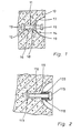
- Fig. 1 einen schematischen Schnitt eines Teiles eines Betonteiles mit bei dessen Herstellung einbetoniertem Verankerungsbolzen, gemäss einem ersten Ausführungsbeispiel,
- Fig. 2 einen schematischen Schnitt etwa entsprechend demjenigen in Fig. 1 mit einem Verankerungsbolzen gemäss einem zweiten Ausführungsbeispiel,
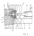
- Fig. 3 einen schematischen Schnitt einer Form für Betonteile mit daran angeordneter Vorrichtung zum Einbetonieren eines Verankerungsbolzens, während des Einbetonierens.
- Für den Transport und das sonstige Handling von Betonteilen 10 beliebiger Art, z. B. von Betonrohren, Schachtringen od. dgl., ist es vorteilhaft, wenn die Betonteile 10 mit Verankerungsbolzen 11 gemäss Fig. 1 versehen sind. Der Verankerungsbolzen 11 weist einen Verankerungsabschnitt 11 mit endseitigem, verdickten, insbesondere etwa tellerförmigen, Verankerungskopf 13 und ferner einen daran anschliessenden, abstehenden Halteabschnitt 14 auf. Der Halteabschnitt 14 trägt am in Fig. 1 rechten freien Ende einen ebenfalls etwa tellerförmigen, verdickten Haltekopf 15, der z. B. so wie der Verankerungskopf 13 gestaltet ist und dabei diesem zugewandt ist. Der Haltekopf 15 kann hinsichtlich seiner Form vielfältig und beliebig beschaffen sein. Er kann als Kugelkopf oder ähnlich ausgebildet sein. Zwischen dem Verankerungskopf 13 und dem Haltekopf 15 erstreckt sich durchgängig ein zylindrischer Schaft 16. Während der Herstellung des Betonteiles 10 ist der Verankerungsbolzen 11 gleich mit einbetonierbar, wobei dessen Verankerungsabschnitt 12 mit Verankerungskopf 13 innerhalb des Betonteiles 10 verankerbar ist, während im Bereich des vorderen Halteabschnittes 14 um diesen herum mittels eines Aussparkörpers ein z. B. etwa glokkenförmiger oder insbesondere halbkugelförmiger Freiraum 17 geschaffen wird, in den der Halteabschnitt 14 frei vorsteht.
- Der Verankerungsbolzen 11 ist derart gestaltet, dass er ein vollautomatisches Einbringen in Massenproduktion in die Betonteile 10 möglich macht. Dazu ist auf der Länge zwischen dem Verankerungskopf 13 und dem Haltekopf 15 ein Führungsteil 18 angeordnet, der beim ersten Ausführungsbeispiel in Fig. 1 aus einem Ring 19 gebildet ist. Die äussere Form und Grösse des Führungsteiles 18, insbesondere des Ringes 19, ist im wesentlichen so gewählt wie diejenigen des Verankerungskopfes 13. Der Führungsteil 18 ist ebenfalls tellerförmig ausgebildet und damit rund. Er weist den gleichen Aussendurchmesser auf wie der entsprechend gestaltete Verankerungskopf 13. Dabei ist der Aussendurchmesser des Führungsteiles 18 und des Verankerungskopfes 13 gleich oder etwas grösser als der Aussendurchmesser des ebenfalls etwa tellerförmig ausgebildeten Haltekopfes 15. Von besonderem Vorteil ist es, wenn der Haltekopf 15 im Durchmesser etwas kleiner ist als der Verankerungskopf 13 und Führungsteil 18. Beim ersten Ausführungsbeispiel ist der Führungsteil 18 einstückiger Bestandteil des Verankerungsbolzens 11. Er ist einstückig mit dessen Schaft 16. Bei einem anderen, nicht gezeigten Ausführungsbeispiel ist der Führungsteil 18, auch in Gestalt des Ringes 19, statt dessen auf dem Schaft 16 aufgebracht, wobei er darauf lösbar gehalten sein kann und z. B. aus Metall oder auch aus Kunststoff bestehen kann. Wie ersichtlich, hat der Ring 19 einen grösseren Abstand vom Verankerungskopf 13 als vom vorderen Haltekopf 15. Der Abstand ist so bemessen, dass beim vollautomatischen Einbringen der Verankerungsbolzen 11 in geeigneten Vorrichtungen ausgerichtet gehalten und geführt und zugleich rüttelsicher geklemmt und gehalten werden kann. Beim ersten Ausführungsbeispiel ist derVerankerungsbolzen11 komplett mit allen Elementen als Rotationsteil ausgebildet, und zwar als Drehteil, insbesondere als Automaten-Drehteil hergestellt. Bei einem solchen lassen sich die für den störungsfreien Betrieb der Vorrichtung zum vollautomatischen Einbringen der Verankerungsbolzen 11 erforderlichen, relativ engen Toleranzen reproduzierbar und mit geringem Kostenaufwand einhalten, so dass der Verankerungsbolzen 11 in dieser Weise kostengünstig herstellbar ist. Er kann statt dessen auch in anderer Weise, z. B. als Präzisionsgussteil, hergestellt sein, sofern auch dann die Einhaltung relativ enger Toleranzen gewährleistet ist.
- Bei dem in Fig. 2 gezeigten zweiten Ausführungsbeispiel sind für die Teile, die dem ersten Ausführungsbeispiel entsprechen, um 100 grössere Bezugszeichen verwendet, so dass dadurch zur Vermeidung von Wiederholungen auf die Beschreibung des ersten Ausführungsbeispiels Bezug genommen ist.
- Beim zweiten Ausführungsbeispiel weist der Verankerungsbolzen 111 am linken Ende den etwa tellerförmigen Verankerungskopf 113 und am rechten Ende den Haltekopf 115 auf, der hier etwa dem Ausschnitt einer Kugel entsprechend geformt ist. Der Führungsteil 118 besteht hier aus einer Hülse 120, deren Aussendurchmesser unter Einschluss des davon umgebenen Haltekopfes 115 höchstens so gross wie der Aussendurchmesser des Verankerungskopfes 113 gewählt ist. Der Führungsteil 118 ist auf den Schaft 116 aufgebracht, z. B. lösbar darauf aufgezogen. Die Hülse 120 besteht z. B. aus Kunststoff od. dgl. elastischem Material, was ein derartiges Aufziehen erleichtert. Statt dessen kann die Hülse 120 auch auf den Schaft 116 und, wenn nötig, Haltekopf 115 bleibend aufgeschäumt sein.
- Während beim ersten Ausführungsbeispiel für das vollautomatische Einbetonieren des Verankerungsbolzens 11 bei der Herstellung des Betonteiles 10 der Verankerungsbolzen im Bereich des Haltekopfes 15 gespannt und zugleich im Bereich des Ringes 19 ausgerichtet und gehalten werden kann, erfolgt beim Verankerungsbolzen 111 gemäss zweitem Ausführungsbeispiel die ausgerichtete Führung und Halterung durch Angriff an der Hülse 120, wobei das Festspannen im Bereich des Haltekopfes 115 geschehen kann.
- In Fig. 3 ist ein Ausführungsbeispiel einer Vorrichtung 21 gezeigt, die zum Einbringen und Einbetonieren eines Verankerungsbolzens 11 in der Ausgestaltung gemäss erstem Ausführungsbeispiel in ein in einer Form 22 zu bildendes Betonteil 10 während dessen Herstellung geeignet ist. Die Form 22 weist zwei einen Formhohlraum 23 dazwischen begrenzende Formwände 24, 25 auf, von denen die Formwand 25 eine z. B. kreisförmige, dicht verschliessbare Öffnung 26 enthält.
- Die Vorrichtung 21 ist über einen Träger 28 an der Formwand 25 ortsfest gehalten. Sie weist einen etwa glockenförmigen, innen hohlen Formteil in Gestalt eines vorderen Kopfteiles 29 auf, der in horizontaler Richtung in Pfeilrichtung 27 in die Öffnung 26 und in den Formhohlraum 23 hinein vorgeschoben werden kann. Der Kopfteil 29 weist eine etwa glockenförmige, z. B. kugelabschnittförmige, Aussenfläche 30 auf, die im Betonteil 10 den Freiraum 17 formt. In dieser in Fig. 3 gezeigten Formgebungsstellung durchsetzt der Kopfteil 29 mit einem Zylinderabschnitt 31 passgenau und dicht die Öffnung 26. An den Zylinderabschnitt 31 schliesst sich ein aussen überstehender Anschlag 32, z. B. ein Ringbund, an, mit dem der Kopfteil 29 im gezeigten vor- und eingeschobenen Zustand an der Aussenfläche der Formwand 25 unter Abschluss und Abdichtung der Öffnung 26 anliegt, wobei der Kopfteil 29 in Pfeilrichtung 27 mit seinem Anschlag 32 gegen die Formwand 25 dauerhaft fest angepresst ist.
- Der Kopfteil 29 ist an einem dazu koaxialen Führungsrohr 33 gehalten. Dieses weist zumindest im Bereich des Kopfteiles 29 eine Führung auf, die hier als Führungsbohrung 34 ausgebildet ist und sich durch den Kopfteil 29 bis zu dessen vorderem Ende mit gleichem Durchmesser fortsetzt und dort nach aussen frei ausmündet. Innerhalb der Führungsbohrung 34 ist der Verankerungsbolzen 11 zumindest mit seinem Halteabschnitt 14 koaxial zur Führungsbohrung 34 ausgerichtet und gehalten. Bei diesem Ausführungsbeispiel ist der Verankerungsbolzen 11 von Hand mit dem Halteabschnitt 14 voran in das freie Ende der Führungsbohrung 34 eingesteckt worden, und zwar in einem Zustand, bei dem der Kopfteil 29 mit Führungsrohr 33 gegensinnig zum Pfeil 27 ganz zurückgefahren ist, und zwar so weit zurück, dass zwischen dem vorderen Ende des Kopfteiles 29 und der Formwand 25 noch ausreichend Platz verbleibt, um einen Verankerungsbolzen 11 in die Führungsbohrung 34 von vorn her manuell einzusetzen.
- Am Führungsrohr 33 greift ein Antrieb 35 an, mittels dessen der Kopfteil 29 mit Führungsrohr 33 in den Formhohlraum 23 unter Abschluss und Abdichtung des Durchlasses 26 in der Formwand 25 in Pfeilrichtung 27 einschiebbar und mittels dessen die gleichen Teile nach der Formgebung gegensinnig zum Pfeil 27 unter Freigabe des einbetonierten Verankerungsbolzens 11 wieder heraus-und abziehbar sind.
- Der Antrieb 35 weist einen Translationsantrieb, insbesondere einen hydraulischen oder pneumatischen Arbeitszylinder 36, auf. Dieser ist wie folgt gebildet. Das Führungsrohr 33 bildet die Kolbenstange dieses Arbeitszylinders 36, die am rechten Ende einen vorzugsweise beidseitig beaufschlagbaren Kolben 37 trägt, der in einem Zylindergehäuse 38 gehalten und geführt ist. Das Zylindergehäuse 38 sitzt am Träger 28. Die Längsmittelachse des Arbeitszylinders 36 verläuft quer, insbesondere etwa rechtwinklig zur Formwand 25. An seinem vorderen Ende ist das Führungsrohr 33 im Inneren hohl unter Bildung der dortigen Führungsbohrung 34.
- Die Vorrichtung 21 ist mit einer Spanneinrichtung 39 am vorderen Ende des Führungsrohres 33 versehen, mittels der der Verankerungsbolzen 11 im Bereich seines Halteabschnittes 14, hier seines Haltekopfes 15, festspannbar ist. Die Spanneinrichtung 39 ist zwischen dem Führungsrohr 33 und dem Kopfteil 29 angeordnet und wirksam. Die Spanneinrichtung 39 weist eine am Führungsrohr 33 befestigte Spannzange 40 auf, deren Spannbacken 41 im Inneren die Führungsbohrung 34 enthalten, wobei die Spannbacken 41 den Verankerungsbolzen 11 an dessen Haltekopf 15 erfassen und festspannen. Der Kopfteil 29 weist im Inneren eine sich zum vorderen Ende etwa kegelstumpfförmig verjüngende Spannfläche 42 auf, die der Aussenfläche der Spannbacken 41 angepasst und zugeordnet ist. Beim Vorschieben des Führungsrohres 33 und Einschieben der Spannbacken 41 in den Kopfteil 29 beaufschlagt die Spannfläche 42 die Spannbacken 41 in Schliess- und Spannrichtung, während sich die Spannbacken 41 beim Zurückziehen gegensinnig zum Pfeil 27 unter Federkraft selbsttätig wieder öffnen können und dann den Haltekopf 15 freigeben. Die Spannzange 40 enthält im Inneren einen nur schematisch angedeuteten Axialanschlag 43, der z. B. aus elastisch zusammendrückbarem Material, z. B. aus Gummi, Schaumstoff od. dgl., bestehen kann. Mittels dieses Axialanschlages 43 ist die Einstecktiefe eines von Hand von vorn her in die Führungsbohrung 34 einsteckbaren Verankerungsbolzens 11 derart begrenzbar, dass im eingesteckten Zustand, wie gezeigt, der Ring 19 des Führungsteiles 18 sich noch im Bereich des Kopfteiles 29 befindet und dort innerhalb der Führungsbohrung 34 ausgerichtet und geführt ist und der Haltekopf 15 sich im Bereich der vorderen Enden der Spannbacken 41 befindet und mittels der Spannbacken 41, wie gezeigt, festklemmbar ist.
- Der Kopfteil 29 ist axial verschiebbar auf der Spannzange 40 des Führungsrohres 33 gehalten und geführt. Das Führungsrohr 33 trägt einen daran festen radialen Anschlag 44, insbesondere Anschlagring, der in einem an den Anschlag 32 des Kopfteiles 29 anschliessenden Ringraum 45 aufgenommen ist. Der Ringraum 45 wird einerseits durch den Anschlag 32 auf einer Seite des Anschlages 44 und andererseits durch eine am Ringraumende befindliche Anschlagfläche 46 begrenzt. Im Ringraumbereich zwischen dem ringförmigen Anschlag 44 und ringförmigen Anschlag 32 befindet sich zumindest eine als Druckfeder ausgebildete Rückstellfeder 47, die z. B. als Tellerfeder ausgebildet ist.
- Die Vorrichtung 21 arbeitet wie folgt. Bei jedem Arbeitstakt wird ein Verankerungsbolzen 11 in der in Fig. 3 gezeigten Ausrichtung von Hand in die Vorrichtung 21 eingesteckt. Dies geschieht in einer Position, bei der über den Arbeitszylinder 36 das Führungsrohr 33 mitsamt der Spannzange 40 und dem Kopfteil 29 gegensinnig zum Pfeil 27 in eine völlig zurückgefahrene Position bewegt ist. Der Hub ist dabei so gross bemessen, dass zwischen dem vorderen Ende des Kopfteiles 29 und der Formwand 25 ausreichend Platz verbleibt, damit man von aussen problemlos den Verankerungsbolzen 11 mit seinem Halteabschnitt 14 voran in die Führungsbohrung 34 einstecken kann. Die Rückstellfeder 47 ist dabei entlastet. Der Anschlag 44 liegt an der Anschlagfläche 46 an, über die bei der Rückzugsbewegung die Mitnahme des Kopfteiles 29 erfolgt ist.
- Beim Einstecken des Verankerungsbolzens 11 in der zurückgezogenen Stellung der Vorrichtung 21 wird die Einstecktiefe durch den Axialanschlag 43 so begrenzt, dass sich der Ring 19 im Bereich der Führungsbohrung 34 befindet und so eine Führung des Verankerungsbolzens 11 in diesem Bereich geschieht und dass sich der Haltekopf 15 im Spannbereich der Spannbacken 41 befindet und somit in diesem axial in Abstand befindlichen Bereich ebenfalls eine Führung für den Verankerungsbolzen 11 gegeben ist, der auf diese Weise reproduzierbar exakt koaxial zur Längsmittellinie des Führungsrohres 33 ausgerichtet ist und bleibt. Die Spannzange 40 ist in diesem Stadium noch nicht wirksam.
- Nun wird der Arbeitszylinder 36 aktiviert, wodurch das Führungsrohr 33 mit dem Kopfteil 29 und eingesteckten Verankerungsbolzen 11 in Pfeilrichtung 27 vorgeschoben wird, wobei der Kopfteil 29 in beschriebener Weise durch die Öffnung 26 in der Formwand 25 hindurch in die in Fig. 3 gezeigte Position bewegt wird. Dabei wird der Kopfteil 29 mit seinem ringförmigen Anschlag 32 fest gegen die Formwand 25 gepresst, wodurch eine zusätzliche gute Abdichtung gewährleistet ist. Die Presskraft wird vom ringförmigen Anschlag 44 über die Rückstellfeder 47 auf den Anschlag 32 übertragen. Findet der Anschlag 32 für diese Abdichtung durch Anpressung hinreichend Widerstand, so wird die Rückstellfeder 47 zusammengepresst. Dadurch verschiebt sich die Spannzange 40 in Pfeilrichtung 27 relativ zum Kopfteil 29 axial weiter in den Kopfteil 29 hinein. Dessen kegelstumpfförmige Spannfläche 42 wirkt mit den Spannbacken 41 so zusammen, dass jene radial nach innen beaufschlagt werden und den Haltekopf 15 des Verankerungsbolzens 11 festspannen. Dieser ist nun in der Vorrichtung 21 fest gehalten. Nun wird in den Formhohlraum Beton eingefüllt und durch Rütteln verdichtet. Während dieses gesamten Rüttel- und Verdichtungsvorganges ist die Vorrichtung 21 über den hydraulischen oder pneumatischen Arbeitszylinder 36 dauerhaft und fest an die Formwand 25 angepresst und verspannt. Es sind keinerlei lose Teile mehr vorhanden. Der Kopfteil 29 und der festgespannte Verankerungsbolzen 11 bilden also praktisch ein mit der Formwand 25 festes Teil, so dass auch in diesem Bereich die Rüttelkräfte wirksam sind und übertragen werden. Es ergibt sich daher auch in diesem Bereich ein homogenes, zufriedenstellendes Betongefüge. Dies gewährleistet eine reproduzierbar feste und sichere Verankerung des Verankerungsbolzens 11 im Betonteil 10.
- Ist der Verdichtungsvorgang des Betonteiles 10 abgeschlossen, so wird der Arbeitszylinder 36 in Richtung gegensinnig zum Pfeil 27 aktiviert. Das Führungsrohr 33 wird nach rechts gezogen. Bedingt durch die Rückstellfeder 47 und den axialen Zwischenraum zwischen dem Anschlag 44 und der Anschlagfläche 46 wird dabei zunächst die Spannzange 40 relativ zum Kopfteil 29 aus diesem herausgezogen und so weit entspannt, dass deren entspannte Spannbacken 41 den Haltekopf 15 des Verankerungsbolzens 11 freigeben. Der Kopfteil 29 ist dagegen noch an die Formwand 25 angepresst. Erst bei der weiteren Rückzugsbewegung des Führungsrohres 33 trifft der Anschlag 44 auf die Anschlagfläche 46 auf, wodurch dann der Kopfteil 29 mitgenommen und gegensinnig zum Pfeil 27 zusammen mit dem Führungsrohr 33 abgezogen wird, unter Freigabe des zuvor einbetonierten Verankerungsbolzens 11, der nun im Betonteil 10 verbleibt und die Position hat, die Fig. 1 zeigt.
- Bei einem anderen, nicht gezeigten Ausführungsbeispiel weisen die Spannbacken 41 im Inneren Stufen auf, die einen Anschlag zur Begrenzung der Einstecktiefe des von Hand einzustekkenden Verankerungsbolzens 11 bilden und den Axialanschlag 43 ersetzen.
- Bei einem anderen, nicht gezeigten Ausführungsbeispiel ist das Führungsrohr 33 in die Spannzange 40 und deren Führungsbohrung 34 hinein mit reduziertem Durchmesser fortgesetzt, wobei dieser Abschnitt die Funktion des Axialanschlages 43 erfüllt.
- Bei einem anderen, nicht gezeigten Ausführungsbeispiel ist als Axialanschlag ein Permanentmagnet vorgesehen, der z. B. an einem in die Führungsbohrung 34 der Spannzange 40 hineinragenden Absatz des Führungsrohres 33 am vorderen Ende gehalten ist. Der Permanentmagnet gewährleistet eine zusätzliche Halterung eines von Hand eingesteckten Verankerungsbolzens 11 und sichert dessen Positionierung.
Claims (11)
Priority Applications (1)
| Application Number | Priority Date | Filing Date | Title |
|---|---|---|---|
| AT87900097T ATE47454T1 (de) | 1985-12-06 | 1986-12-03 | Verankerungsbolzen fuer betonteile. |
Applications Claiming Priority (3)
| Application Number | Priority Date | Filing Date | Title |
|---|---|---|---|
| DE8536798U DE8536798U1 (de) | 1985-12-06 | 1985-12-06 | Verankerungsbolzen für Betonteile |
| DE3543195 | 1985-12-06 | ||
| DE3543195A DE3543195C2 (de) | 1985-12-06 | 1985-12-06 | Verankerungsbolzen für Betonteile sowie Verfahren und Vorrichtung zum Einbringen und Einbetonieren solcher Verankerungsbolzen |
Publications (2)
| Publication Number | Publication Date |
|---|---|
| EP0248061A1 EP0248061A1 (de) | 1987-12-09 |
| EP0248061B1 true EP0248061B1 (de) | 1989-10-18 |
Family
ID=37834114
Family Applications (2)
| Application Number | Title | Priority Date | Filing Date |
|---|---|---|---|
| EP86116159A Withdrawn EP0230542A1 (de) | 1985-12-06 | 1986-11-21 | Verfahren und Vorrichtung zum Einbringen und Einbetonieren eines Verankerungsbolzens in ein Betonteil |
| EP87900097A Expired EP0248061B1 (de) | 1985-12-06 | 1986-12-03 | Verankerungsbolzen für betonteile |
Family Applications Before (1)
| Application Number | Title | Priority Date | Filing Date |
|---|---|---|---|
| EP86116159A Withdrawn EP0230542A1 (de) | 1985-12-06 | 1986-11-21 | Verfahren und Vorrichtung zum Einbringen und Einbetonieren eines Verankerungsbolzens in ein Betonteil |
Country Status (4)
| Country | Link |
|---|---|
| EP (2) | EP0230542A1 (de) |
| DE (2) | DE3543195C2 (de) |
| DK (1) | DK156036C (de) |
| WO (1) | WO1987003638A1 (de) |
Families Citing this family (10)
| Publication number | Priority date | Publication date | Assignee | Title |
|---|---|---|---|---|
| DE3808379A1 (de) * | 1988-03-12 | 1989-09-28 | Detec Fertigung Gmbh | Vorrichtung zum einsetzen von transportankern in schalungen fuer betonteile |
| FR2649738B1 (fr) * | 1989-07-17 | 1993-06-11 | Marcel Arteon | Ancre notamment pour panneau de beton |
| DK110590D0 (da) * | 1990-05-03 | 1990-05-03 | Pedershaab Maskinfabrik As | Fremgangsmaade og apparat til stoebning af et betonlegeme |
| EP0943746A3 (de) | 1998-03-20 | 2001-04-11 | Erico International Corporation | Ankerstange und Betonbewehrungsverfahren |
| DE29805988U1 (de) | 1998-04-01 | 1998-07-09 | Siemens AG, 80333 München | Vorrichtung zum Übertragen einer Kraft |
| GB2360563A (en) * | 2000-03-22 | 2001-09-26 | Lindley Parapet Systems Ltd | An anchor having a longitudinal recess |
| AT408859B (de) * | 2000-03-29 | 2002-03-25 | Maba Fertigteilind Gmbh | Ringförmige dichtung |
| NO328275B1 (no) * | 2007-08-01 | 2010-01-18 | Sb Produksjon As | Sammenforingssystem for to bygningselementer og fremgangsmate for sammenforing av to bygningselementer. |
| AT521682B1 (de) * | 2018-11-12 | 2020-04-15 | Ulrich Schluesselbauer | Vorrichtung zum Halten eines Hebeankers für ein Werkstück aus Beton |
| AT523387B1 (de) * | 2020-04-29 | 2021-08-15 | Mmk Holz Beton Fertigteile Gmbh | Verbundfertigteil |
Family Cites Families (6)
| Publication number | Priority date | Publication date | Assignee | Title |
|---|---|---|---|---|
| DE1918965A1 (de) * | 1969-04-15 | 1970-11-12 | Heinrich Geisel | Anordnung und Vorrichtung zum Anordnen der Verankerungsoesen bei Kunststeineinfassungen |
| BE790435A (fr) * | 1971-10-26 | 1973-02-15 | Rapid Metal Developments Ltd | Garniture d'etancheite |
| DE3219139A1 (de) * | 1982-05-21 | 1983-11-24 | DETEC Fertigung GmbH, 6080 Groß-Gerau | Verfahren und vorrichtung zum einsetzen von transportankern in betonfertigteile |
| US4569167A (en) * | 1983-06-10 | 1986-02-11 | Wesley Staples | Modular housing construction system and product |
| DE8409825U1 (de) * | 1984-03-30 | 1984-06-28 | Pape, Harald, 4930 Detmold | Vorrichtung zum Einbringen von Transportankern in eine Gießform für Betonteile |
| DE3413291A1 (de) * | 1984-04-09 | 1985-10-17 | Wagener & Polascheck Vertriebsgesellschaft mbH, 4800 Bielefeld | Vorrichtung zum einlegen von transportankern in betonfertigteile |
-
1985
- 1985-12-06 DE DE3543195A patent/DE3543195C2/de not_active Expired - Fee Related
- 1985-12-06 DE DE8536798U patent/DE8536798U1/de not_active Expired
-
1986
- 1986-11-21 EP EP86116159A patent/EP0230542A1/de not_active Withdrawn
- 1986-12-03 EP EP87900097A patent/EP0248061B1/de not_active Expired
- 1986-12-03 WO PCT/EP1986/000699 patent/WO1987003638A1/de not_active Ceased
-
1987
- 1987-08-05 DK DK408487A patent/DK156036C/da not_active IP Right Cessation
Also Published As
| Publication number | Publication date |
|---|---|
| DE3543195A1 (de) | 1987-06-11 |
| DK156036B (da) | 1989-06-19 |
| WO1987003638A1 (fr) | 1987-06-18 |
| EP0248061A1 (de) | 1987-12-09 |
| DK408487D0 (da) | 1987-08-05 |
| DE3543195C2 (de) | 1995-04-20 |
| DK156036C (da) | 1989-11-13 |
| DK408487A (da) | 1987-08-05 |
| DE8536798U1 (de) | 1986-06-26 |
| EP0230542A1 (de) | 1987-08-05 |
Similar Documents
| Publication | Publication Date | Title |
|---|---|---|
| EP0383723B1 (de) | Verfahren, Verankerungsglied und Spannvorrichtung zum Spannen eines Stabes | |
| DE7027912U (de) | Rohrfoermiger blindniet. | |
| EP0248061B1 (de) | Verankerungsbolzen für betonteile | |
| DE1928490B2 (de) | Schloßmutter | |
| DE8905863U1 (de) | Vorrichtung zum Bruchtrennen von Pleueln | |
| EP1424453B1 (de) | Verbindungsmuffe | |
| EP0275441A1 (de) | Spannvorrichtung | |
| DE3710829A1 (de) | Vorrichtung zum montieren von dichtungsringen | |
| DE2537644C3 (de) | Dübel zum Verankern insbesondere in Gipskartonwänden | |
| DE3744046A1 (de) | Verfahren und vorrichtung zum aushalsen von blechrohren | |
| DE1926975B2 (de) | Vorrichtung zum Befestigen eines Kletterschalungselementes | |
| DE2558165C2 (de) | Vorrichtung zur Endmontage eines Stoßdämpfers | |
| DE69003364T2 (de) | Einrichtung zum Einfahren von Gewindeverbindungen für Rohrstränge durch Festschrauben und Losdrehen. | |
| DE4233304A1 (de) | Kupplungsmuffe und Verfahren zur Herstellung einer Kupplungsmuffe | |
| DE1987933U (de) | Vorrichtung zum spannen beziehungsweise vorspannen eines laenglichen verstaerkungselements fuer beton. | |
| DE3101205C2 (de) | ||
| DE3428123C2 (de) | ||
| DE4140407C2 (de) | Verfahren zum Herstellen einer Verbindung zwischen wenigstens zwei Längen eines Betonstahls | |
| DE8534383U1 (de) | Vorrichtung zum Einbringen und Einbetonieren eines Verankerungsbolzens | |
| DE2106921A1 (de) | Spannvorrichtungen oder - winden, insbesondere für Bauwerksarmaturen | |
| DE20108475U1 (de) | Bewehrungselement für ein Betonfertigteil, Schalungsteil zur Aufnahme des Bewehrungselements und Betonfertigteil | |
| DE4015676C2 (de) | Vorrichtung zur Herstellung von keramischen Abzweigrohren | |
| DE2343267A1 (de) | An einem hohlprofil ueber mindestens zwei schrauben befestigtes tuerband | |
| DE6606695U (de) | Vorrichtung zum einfuehren von einlegeteilen in pressformen | |
| DE2117471A1 (de) | Verfahren und Vorrichtung zum Befestigen von Anschlußteilen an Bauelementen |
Legal Events
| Date | Code | Title | Description |
|---|---|---|---|
| PUAI | Public reference made under article 153(3) epc to a published international application that has entered the european phase |
Free format text: ORIGINAL CODE: 0009012 |
|
| AK | Designated contracting states |
Kind code of ref document: A1 Designated state(s): AT BE CH DE FR GB IT LI LU NL SE |
|
| 17P | Request for examination filed |
Effective date: 19871103 |
|
| RAP1 | Party data changed (applicant data changed or rights of an application transferred) |
Owner name: DEHA ANKERSYSTEME GMBH & CO. KG |
|
| 17Q | First examination report despatched |
Effective date: 19890124 |
|
| GRAA | (expected) grant |
Free format text: ORIGINAL CODE: 0009210 |
|
| AK | Designated contracting states |
Kind code of ref document: B1 Designated state(s): AT BE CH DE FR GB IT LI LU NL SE |
|
| PG25 | Lapsed in a contracting state [announced via postgrant information from national office to epo] |
Ref country code: IT Free format text: LAPSE BECAUSE OF FAILURE TO SUBMIT A TRANSLATION OF THE DESCRIPTION OR TO PAY THE FEE WITHIN THE PRESCRIBED TIME-LIMIT;WARNING: LAPSES OF ITALIAN PATENTS WITH EFFECTIVE DATE BEFORE 2007 MAY HAVE OCCURRED AT ANY TIME BEFORE 2007. THE CORRECT EFFECTIVE DATE MAY BE DIFFERENT FROM THE ONE RECORDED. Effective date: 19891018 Ref country code: BE Effective date: 19891018 Ref country code: FR Free format text: THE PATENT HAS BEEN ANNULLED BY A DECISION OF A NATIONAL AUTHORITY Effective date: 19891018 Ref country code: GB Effective date: 19891018 |
|
| REF | Corresponds to: |
Ref document number: 47454 Country of ref document: AT Date of ref document: 19891115 Kind code of ref document: T |
|
| REF | Corresponds to: |
Ref document number: 3666481 Country of ref document: DE Date of ref document: 19891123 |
|
| PGFP | Annual fee paid to national office [announced via postgrant information from national office to epo] |
Ref country code: CH Payment date: 19891208 Year of fee payment: 4 |
|
| PGFP | Annual fee paid to national office [announced via postgrant information from national office to epo] |
Ref country code: AT Payment date: 19891229 Year of fee payment: 4 |
|
| PG25 | Lapsed in a contracting state [announced via postgrant information from national office to epo] |
Ref country code: LU Free format text: LAPSE BECAUSE OF NON-PAYMENT OF DUE FEES Effective date: 19891231 |
|
| PGFP | Annual fee paid to national office [announced via postgrant information from national office to epo] |
Ref country code: NL Payment date: 19891231 Year of fee payment: 4 |
|
| PGFP | Annual fee paid to national office [announced via postgrant information from national office to epo] |
Ref country code: DE Payment date: 19900122 Year of fee payment: 4 |
|
| EN | Fr: translation not filed | ||
| GBV | Gb: ep patent (uk) treated as always having been void in accordance with gb section 77(7)/1977 [no translation filed] | ||
| PLBE | No opposition filed within time limit |
Free format text: ORIGINAL CODE: 0009261 |
|
| STAA | Information on the status of an ep patent application or granted ep patent |
Free format text: STATUS: NO OPPOSITION FILED WITHIN TIME LIMIT |
|
| 26N | No opposition filed | ||
| PG25 | Lapsed in a contracting state [announced via postgrant information from national office to epo] |
Ref country code: AT Effective date: 19901203 |
|
| PGFP | Annual fee paid to national office [announced via postgrant information from national office to epo] |
Ref country code: SE Payment date: 19901221 Year of fee payment: 5 |
|
| PG25 | Lapsed in a contracting state [announced via postgrant information from national office to epo] |
Ref country code: LI Effective date: 19901231 Ref country code: CH Effective date: 19901231 |
|
| PG25 | Lapsed in a contracting state [announced via postgrant information from national office to epo] |
Ref country code: NL Effective date: 19910701 |
|
| NLV4 | Nl: lapsed or anulled due to non-payment of the annual fee | ||
| REG | Reference to a national code |
Ref country code: CH Ref legal event code: PL |
|
| PG25 | Lapsed in a contracting state [announced via postgrant information from national office to epo] |
Ref country code: DE Effective date: 19910903 |
|
| PG25 | Lapsed in a contracting state [announced via postgrant information from national office to epo] |
Ref country code: SE Effective date: 19911204 |
|
| EUG | Se: european patent has lapsed |
Ref document number: 87900097.4 Effective date: 19920704 |