EP0241850B1 - Dispositif de tirage de fil - Google Patents
Dispositif de tirage de fil Download PDFInfo
- Publication number
- EP0241850B1 EP0241850B1 EP87105166A EP87105166A EP0241850B1 EP 0241850 B1 EP0241850 B1 EP 0241850B1 EP 87105166 A EP87105166 A EP 87105166A EP 87105166 A EP87105166 A EP 87105166A EP 0241850 B1 EP0241850 B1 EP 0241850B1
- Authority
- EP
- European Patent Office
- Prior art keywords
- thread
- supply mechanism
- roller
- suction
- channel
- Prior art date
- Legal status (The legal status is an assumption and is not a legal conclusion. Google has not performed a legal analysis and makes no representation as to the accuracy of the status listed.)
- Expired - Lifetime
Links
- 230000007246 mechanism Effects 0.000 claims description 64
- 230000002093 peripheral effect Effects 0.000 claims description 18
- 238000000034 method Methods 0.000 claims description 11
- 230000001154 acute effect Effects 0.000 claims description 8
- 238000009987 spinning Methods 0.000 claims description 6
- 230000008569 process Effects 0.000 claims description 4
- 238000000605 extraction Methods 0.000 claims 4
- 238000004804 winding Methods 0.000 description 37
- 230000015572 biosynthetic process Effects 0.000 description 10
- 239000002699 waste material Substances 0.000 description 10
- 239000011324 bead Substances 0.000 description 4
- 239000000835 fiber Substances 0.000 description 3
- 239000007788 liquid Substances 0.000 description 3
- 241000282461 Canis lupus Species 0.000 description 2
- 238000007792 addition Methods 0.000 description 2
- 230000008901 benefit Effects 0.000 description 2
- 238000007664 blowing Methods 0.000 description 2
- 238000010276 construction Methods 0.000 description 2
- 230000007423 decrease Effects 0.000 description 2
- 230000003247 decreasing effect Effects 0.000 description 2
- 230000000694 effects Effects 0.000 description 2
- 230000001105 regulatory effect Effects 0.000 description 2
- 239000000126 substance Substances 0.000 description 2
- XLYOFNOQVPJJNP-UHFFFAOYSA-N water Substances O XLYOFNOQVPJJNP-UHFFFAOYSA-N 0.000 description 2
- 238000003466 welding Methods 0.000 description 2
- 230000008859 change Effects 0.000 description 1
- 230000002349 favourable effect Effects 0.000 description 1
- 230000003993 interaction Effects 0.000 description 1
- 238000011144 upstream manufacturing Methods 0.000 description 1
Images


Classifications
-
- D—TEXTILES; PAPER
- D04—BRAIDING; LACE-MAKING; KNITTING; TRIMMINGS; NON-WOVEN FABRICS
- D04H—MAKING TEXTILE FABRICS, e.g. FROM FIBRES OR FILAMENTARY MATERIAL; FABRICS MADE BY SUCH PROCESSES OR APPARATUS, e.g. FELTS, NON-WOVEN FABRICS; COTTON-WOOL; WADDING ; NON-WOVEN FABRICS FROM STAPLE FIBRES, FILAMENTS OR YARNS, BONDED WITH AT LEAST ONE WEB-LIKE MATERIAL DURING THEIR CONSOLIDATION
- D04H3/00—Non-woven fabrics formed wholly or mainly of yarns or like filamentary material of substantial length
- D04H3/02—Non-woven fabrics formed wholly or mainly of yarns or like filamentary material of substantial length characterised by the method of forming fleeces or layers, e.g. reorientation of yarns or filaments
- D04H3/03—Non-woven fabrics formed wholly or mainly of yarns or like filamentary material of substantial length characterised by the method of forming fleeces or layers, e.g. reorientation of yarns or filaments at random
-
- B—PERFORMING OPERATIONS; TRANSPORTING
- B65—CONVEYING; PACKING; STORING; HANDLING THIN OR FILAMENTARY MATERIAL
- B65H—HANDLING THIN OR FILAMENTARY MATERIAL, e.g. SHEETS, WEBS, CABLES
- B65H51/00—Forwarding filamentary material
- B65H51/20—Devices for temporarily storing filamentary material during forwarding, e.g. for buffer storage
- B65H51/22—Reels or cages, e.g. cylindrical, with storing and forwarding surfaces provided by rollers or bars
-
- B—PERFORMING OPERATIONS; TRANSPORTING
- B65—CONVEYING; PACKING; STORING; HANDLING THIN OR FILAMENTARY MATERIAL
- B65H—HANDLING THIN OR FILAMENTARY MATERIAL, e.g. SHEETS, WEBS, CABLES
- B65H54/00—Winding, coiling, or depositing filamentary material
- B65H54/86—Arrangements for taking-up waste material before or after winding or depositing
- B65H54/88—Arrangements for taking-up waste material before or after winding or depositing by means of pneumatic arrangements, e.g. suction guns
-
- D—TEXTILES; PAPER
- D01—NATURAL OR MAN-MADE THREADS OR FIBRES; SPINNING
- D01D—MECHANICAL METHODS OR APPARATUS IN THE MANUFACTURE OF ARTIFICIAL FILAMENTS, THREADS, FIBRES, BRISTLES OR RIBBONS
- D01D7/00—Collecting the newly-spun products
-
- B—PERFORMING OPERATIONS; TRANSPORTING
- B65—CONVEYING; PACKING; STORING; HANDLING THIN OR FILAMENTARY MATERIAL
- B65H—HANDLING THIN OR FILAMENTARY MATERIAL, e.g. SHEETS, WEBS, CABLES
- B65H2701/00—Handled material; Storage means
- B65H2701/30—Handled filamentary material
- B65H2701/31—Textiles threads or artificial strands of filaments
Definitions
- the invention relates to a thread take-off device for pulling a continuously running thread with a suction device which removes the thread in an air stream.
- the invention relates to methods for applying a freshly spun chemical thread coming from the spinneret to rapidly rotating machine parts.
- the invention solves the problem of designing the so-called suction guns or other suction devices in such a way that they can apply sufficiently high thread tensile forces even at high thread speeds of more than 4,000 m / min.
- Suction guns or other suction devices serve the purpose of pulling off continuously occurring threads, in particular man-made fibers during the business interruption, for example during the bobbin change in a man-made fiber spinning machine, and feeding them to the waste.
- the thread is subjected to a strong air flow in these suction pistols.
- the limit of the possibility of using such devices is at thread speeds of approx. 4000 m / min (65 to 70 m / s). It becomes particularly impossible to apply the necessary thread tensions when the thread is to be placed on godets or winding machines and / or is conveyed by means of godets. There is a risk that the thread will form a winder on the godet / winding machine due to insufficient thread tension.
- the compressors or are required because of the very high power requirement Vacuum pumps represent a significant cost factor, although these machines are only needed for short periods in the event of business interruptions.
- the threading device is arranged directly upstream of the suction device.
- This thread feed mechanism consists of at least one driven roller to be looped by the thread.
- the suction mouth is arranged in the immediate vicinity of the surface of the roll in the thread path behind the roll and preferably on an outlet tangent thereof.
- the invention further provides measures by which it is ensured that the thread does not form any winders on the thread feed mechanism.
- this two rollers arranged at a short distance from one another and rotating in the same direction are provided, at least one of which can be driven and the roller axes of which are interleaved or form an acute angle with one another.
- the thread is guided over this feed mechanism in such a way that it runs onto the rollers in the area of the wide center distance and that the suction device is arranged in the area of the small roller distance.
- the suction device can connect to the lower works substantially in the axial direction or encompass the end of the supply works, whereby a thread guide must be present which prevents the thread from unwinding again overhead from the supply works.
- the suction device can be arranged transversely to the roll axes, so that the thread is drawn off tangentially from the rolls.
- the formation of the winder is avoided in that the thread feed mechanism is formed from only one roll, which is of conical design.
- the roll is cantilevered at its thick end, so that any curlers that may form always slide off towards the thin end and can be removed there.
- a constant, axial feed is effected, so that _ as with the delivery unit with two rollers, the axes of which are interlaced with one another, _ several turns are not superimposed.
- the thread take-off device according to this invention can be mounted as a stationary unit, in which case mechanical or pneumatic means for applying the thread to the thread feed mechanism must be provided at the same time. Above all, however, the thread take-off device can be designed as a portable handling device, comparable to the previous suction pistols.
- the following method is proposed, in particular in chemical fiber spinning systems: the thread which is produced by the spinneret at a relatively low speed is first caught by the suction device, so that the thread is drawn off with the tensile force that can be generated by the suction device alone. Now the handling device is pivoted in such a way that the roller axis or roller axes traverse the thread path once or several times in a wobbling movement. As a result, the thread forms one or more loops on the roll or rolls.
- the handling device must be held in this way at the end of this process, or the thread must be inserted in a thread guide located on the handling device at the end of this process. be that it tapers to the roles or the role substantially tangentially. In this way it is avoided that the point of run-up of the thread migrates to the feed mechanism in the axial direction.
- the thread pulling device can now exert such a high thread tension on the thread that the thread can be applied to high-speed machine parts such as godets and / or winding devices without the risk of winder formation.
- the thread feed mechanism When the thread is applied to the thread feed mechanism, it is drawn off with greater tensile force, the tensile force corresponding on the one hand to the torque of the drive motor and on the other hand to the number of wraps.
- the torque characteristics of the motor on the one hand and the number of wraps must be coordinated so that there is no thread breakage.
- the suction device is now only used for the purpose of applying a low tensile force in the thread end running off. This tensile force in the running thread end only has to be so great that a sufficient tensile force in the incoming thread end is induced by wrap friction. On the other hand, only a low tensile force of the running thread end can be compensated for by additional looping.
- An additional possibility for setting and / or regulating the thread tension is given in that the point at which the thread runs up is axially adjustable and in that the thread feed mechanism consists of a conical roller.
- Mechanical devices for thread application can be designed such that the thread pulling device is pivoted about the thread axis after the thread has been caught in the suction device.
- the invention proposes a mechanically simple and safe-acting application device.
- This consists of a thread guide that bypasses the thread feed mechanism on an envelope and thereby traverses the thread path in the area of the suction device.
- the thread guide preferably also gives the thread an axial feed.
- it can be a flyer-like thread guide that is coaxial or parallel to the roll axis or _ in a yarn feed unit that consists of two rollers _ is pivotally mounted in a plane between the roller axes.
- the axial feed can be effected in that the flyer is mounted in a thread or in that the thread guide located on its outer arm is of helical design.
- the invention provides pneumatic threading means which cooperate with the suction device.
- the air flow conveying the thread is guided tangentially on and in a vortex, a roller and then subtracted tangentially.
- the roller is constantly driven with the direction of rotation of the vortex.
- the air flow hits the roller circumference in a normal plane in the area of the thicker end (thread inlet plane).
- the peripheral speed is at least equal to the thread speed.
- the air vortex then continues towards the thinner end of the conical roller.
- the roller for generating the air vortex is surrounded by a flow channel which forms a narrow gap with the roller and is so wide open to the roller that the thread can leave the flow channel.
- the flow channel can be a helically curved, slotted tube.
- the inner shell of this housing forms a narrow gap with the roller.
- the gap width is dimensioned so that the thread on the roller can also form a small winder.
- In the inner casing is a helical flow channel Cut groove that extends around the roller with at least half a turn.
- Thread inlet channel and thread outlet channel which penetrate the housing, open in front of and behind this groove, respectively.
- the channels are preferably aligned with the groove ends.
- the roller can in turn be conical in order to achieve an axial advance of the thread turns.
- the interior of the housing can also be conical.
- Conical rollers also have the advantage that the thread tension is automatically set on them. When a certain tensile force is exceeded, the thread turns slip to the area of the thin end and thus to an area of lower peripheral speed. As described, this effect can also be achieved deliberately by adjusting the thread's point of contact.
- the roller is mounted in a housing which is adapted to the circumference of the roller with a gap.
- the thread inlet channel and the thread discharge channel open into this housing, both channels lying on a tangent to the roller. Otherwise, the inner wall of the housing is smooth.
- the direction of rotation is chosen so that the roll circumference and the air are aligned.
- the air flow generated by the suction device is first deflected to an air vortex on the roller, the so-called Coanda effect also playing a role.
- the thread is thus first drawn around the roller in an air vortex before it is caught by the suction device. It has surprisingly been found that surprisingly good catch safety can also be achieved with this embodiment.
- roller is conical in this embodiment, multiple wrapping of the roller can also be effected by axially displacing the thread suction channel with respect to the thread feed channel to the thin end. Slipping of the thread turns ensures that the free thread end caught by the roller reaches the area of the thread suction channel and is drawn off there.
- a further possibility of the pneumatic application of the thread to the thread delivery unit is provided if the roller of the delivery unit is conical and is overhung.
- the thread suction channel is arranged on a tangent of the roll in the region of the free end without the mouth of the thread suction channel preventing the thread wound on the winding body from slipping off to the free end of the winding body.
- the mouth of the thread suction channel is designed so that it engages around the free end of the conical roller in a plate or pot-like manner.
- the thread is first brought into circumferential contact with the conical roller. It then forms a winder on the conical roller, which slides towards the free, thinner end. The slipping windings fall into the plate or pot-shaped mouth of the thread suction channel. From there they are drawn off by the suction device until the thread is drawn smoothly and runs tangentially from the conical roll.
- the invention is based on the knowledge that it is unproblematic to catch a delivered thread end by means of a suction gun or an air flow, especially if the thread comes fresh from the spinneret.
- the tensile force that is required in order to avoid winder formation at the delivery unit following the spinneret is only possible with mechanical support of the air flow through a delivery unit.
- offers the invention by using the conical roller the advantage that a winder formation at the delivery plant is impossible. Possible winders slip on the conical roller and are always carried along by the air flow escaping through the thread outlet pipe.
- the conical roller is overhung and that the housing is open towards the free end. This ensures that any winders slide over the free end of the roller and can fall out of the housing or be pulled out. It is also possible to connect the open end of the housing to another suction channel, which then opens into the waste.
- rollers are referred to as conical rollers which have a continuously decreasing diameter from the thread run-up level to at least the normal plane in which the thread suction channel lies (thread run-off level).
- conical rollers which have a continuously decreasing diameter from the thread run-up level to at least the normal plane in which the thread suction channel lies (thread run-off level).
- paraboloids, hyperboloid stumps and the like are also considered.
- High-speed electric motors can be used to drive the yarn feed mechanism.
- Air turbines are also advantageously used.
- a sequence control can be used, by means of which initially only the air turbine with the thread supplying unit is put into operation. Only when the yarn feeder has reached its target speed is the suction device also pressurized with compressed air. The thread feed unit can continue to run idle or with a reduced air requirement so that the necessary suction energy is available. After switching on the suction device, the thread is sucked in, applied to the thread feed mechanism and sucked off. Now the air turbine is again charged with the larger part of the available air volume, so that by the The desired tractive force can be applied.
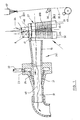
- the suction device consists of the suction pipe 16 and an injector attachment with an annular channel 23, which is connected via air supply 22 to a compressed air source. Blow ducts 21 lead from the ring duct 23 into the thread outlet duct 31, where the compressed air flowing out generates a strong suction flow in the direction of the arrow.
- the yarn feed mechanism 1 Before the inlet of the suction pipe 16, the yarn feed mechanism 1 is arranged transversely to the air duct axis 28.
- the bracket 40 is connected by connection 41 to the wall of the suction pipe 16.
- Two rollers 32, 33 are mounted in the holder 40 in such a way that that the roller axes 45, 46 extend at an acute angle 34 to one another.
- the delivery mechanism 1 It is particularly advantageous for the delivery mechanism 1 to be arranged in front of the intake pipe 16 in such a way that the air duct axis 48 extends essentially in a plane tangent to the two rollers 32, 33.
- the air duct axis 48 strikes the yarn feed mechanism 1 in its end or outlet area 47, while a substantial part of the longitudinal extent of the feed mechanism 1 projects laterally beyond the suction pipe 16. It is therefore provided that the thread runs in the area of the smaller center distance from the delivery mechanism 1.
- the thread outlet 31 is connected to a flexible tube which leads into a waste container.
- the thread take-off device forms a handling unit which has a handle, not shown.
- the suction pipe 16 and / or the thread outlet channel 31 can serve as a handle.
- the roller 32 is driven by a high-speed electric motor in the drive housing 8.
- the drive housing 8 is fastened on the holder 40.
- the roller 33 is freely rotatable in the holder 40.
- the thread coming, for example, from the spinneret 57 is first drawn straight into the suction tube 16 of the suction device 24 in operation: thread run 20.1, shown in broken lines. It should be taken into account that the thread is not delivered by the spinneret 57 at a defined speed. Therefore, the suction forces exerted by the suction device 24 are sufficient to pull off the thread and to prevent it from becoming entangled and knotted.
- the roller 32 has also been set in rotation, the rotational speed of the roller being so high that its peripheral speed essentially corresponds to the nominal speed of the thread and the peripheral speed of the feed mechanism 30, to which that of the spinneret coming thread to be created corresponds.
- the thread pulling device is pivoted several times so that the supply unit 1 executes a wobbling movement around the thread axis, so that the thread which has just been running is looped once or several times around the two rollers 32, 33 of the supply unit
- the delivery mechanism and in particular the driven roller 32 exerts an increasing frictional force on the thread, so that the thread is now drawn off with essentially its desired speed and high tensile force.
- the thread take-off device is now guided several times around the godet 30 and the thread is thereby placed on the godet 30 with the desired number of wraps (thread path 20.2).
- the thread can now be placed with the thread take-off device on a winding device 49, which is only indicated schematically (thread run 20.3).
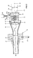
- the delivery unit 1 and the suction device 24 are essentially coaxial or parallel, the outlet end 47 of the delivery unit 1 pointing to the inlet of the expanded suction channel 16. It is shown that the outlet end 47 of the delivery unit 1 projects into the enlarged inlet of the suction channel 16.
- the suction channel 16 opens parallel over the plane in which the two roller axes 45, 46 lie.
- the holder 40 in which the rollers 32, 33 are mounted, is connected to the wall of the suction pipe 16 by connection 41.
- the two roller axes 45, 46 of the delivery mechanism 1 run at an acute angle to one another.
- a cap 43 with counter bearing supports the two rollers on its free end and covers the run-up ends of the two rollers so that its edge largely prevents the thread from slipping off the rollers 32, 33.
- the suction pipe 16 is in turn connected to a suction device 24, which consists of an annular duct 23 with a compressed air connection 22 and the blowing ducts 21 and generate a strong suction flow in the suction pipe 16.
- the thread is discharged into the waste through thread outlet channel 31.
- the thread coming from the spinneret is first caught in the suction tube 16 by the suction device 24 and drawn off straight in the thread path 20.1.
- the thread take-off device is pivoted several times in such a way that the air duct axis 48 and the delivery mechanism execute a wobbling movement around this thread run 20.1, so that a desired number of turns are formed on the delivery mechanism 1.
- the rollers 32 and 33 of the delivery mechanism were put into operation by an air turbine located in the holder 40. Therefore, the thread is now withdrawn from the spinneret at the speed and tensile force specified by the air turbine.
- the connection 41 serves at the same time as a thread guide, which prevents the thread from being pulled off the delivery mechanism by the delivery mechanism due to the suction force exerted by the suction device.
- the thread 20 to be drawn is in each case wrapped in a plurality of turns 36 around the two rollers 32, 33 of the thread feed unit 1 in operation and is drawn off with increased tensile force as a result of the frictional contact between the rollers 32, 33 and the thread which results.
- the arrangement of the two rollers 32, 33 at an angle 34 causes each other that the individual thread turns 36 are axially offset from each other. In the area of the outlet end 47 of the thread feeder 1, the thread is taken over and removed by the suction flow of the suction tube 16.
- the two rollers 32, 33 with their axes 45, 46 form an acute angle 34 to one another.
- the arrangement can also be such that the axes 45 and 46 lie in two substantially parallel planes and thus to one another aligned that they intersect in the projection in one of the two planes at an acute angle.
- At least one of the two rollers 32, 33 is driven at such a high speed that the peripheral speed corresponds at least to the thread speed.
- This can e.g. in that an air turbine is arranged in the holder 40, as described, but the drive by an electric motor is also possible.
- a thread can be applied to godets and other thread conveyors, in particular also to a winding device, at peripheral speeds which are well over 4,000 e.g. 7,000 m / min. This is obviously due to the fact that the necessary thread tension is generated by the thread feed mechanism 1 and can be set so high that no winder forms on the godet or the winding device. High flow velocities are then required to remove the thread running from the feed mechanism 1, but only relatively low tensile forces are required.
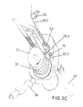
- FIGS. 3A, 3B, 3C serve to explain a thread take-off device with an application device for the thread.
- the rollers 32 and 33 of the thread feed mechanism 1 are rotatably mounted on the holder 40.
- Roller 33 is driven by a turbine, whose housing is designated 8, driven.
- the roller axes of rollers 32 and 33 intersect at an acute angle.
- Heath rollers are mounted in the holder 40 in such a way that their center distance decreases from their free end to their bearing end 47.
- the drive direction of the roller 33 is indicated by arrow 35.
- the suction device lying in the holding device 40, the suction tube 16 of which lies between the two rollers 32 and 33 and above the plane connecting the roller axes, is accommodated in the holder 40.
- the suction device consists, as has already been described for the embodiment of FIGS. 1 and 2, of an annular channel, which surrounds the suction channel 16 and is connected to it by blowing channels.
- the ring channel is supplied with compressed air through a compressed air connection 22.
- the compressed air connection 22 penetrates a handle 39 at the same time.
- the channel guide inside the holder 40 is not shown in detail.
- the thread application device is a U-shaped bracket 50.
- the bracket 50 is pivotally mounted at one end in the holder 40. The end is arranged essentially parallel to the bisector between the two roller axes. Furthermore, the pivot bearing in the holder 40 and the bearing end of the bracket 50 has a high helix thread 51, the function of which will be described later.
- a thread guide 52 is mounted on the other U flank. This thread guide 52 is a so-called "wolf tooth", i.e. the thread guide 52 has a catch slot into which the thread can enter laterally but not out again.
- the thread guide 52 is pivotable about axis 53, but the thread guide is not axially movable.
- the bracket 50 can be pivoted in the direction of the arrow 54, ie in the direction of rotation of the yarn feed mechanism.
- the suction device ends in a thread outlet channel 31 to which a waste bag 44 is clamped.
- the steep thread 51 is designed so that when the bracket 50 is pivoted in the direction of arrow 54, the bracket executes an axial movement in the direction of arrow 55.
- the thread pulling device is handled as follows for thread catching and for threading the thread on a godet; First, the thread coming from a spinneret, not shown, is brought into the area of the mouth of the suction tube 16 and drawn off. This is possible because the thread is not delivered by the spinneret at a defined and particularly high speed. In the meantime, the air turbine in the housing 8 has also been pressurized with compressed air and consequently the roller 33 is set in rotation, so that the roller is driven essentially at the desired peripheral speed of the godet 30 (FIG. 3C) to which the thread is to be applied. The thread has a thread run 20.1 (Fig. 3A). The bracket 50 is now rotated against the direction of the arrow 54.
- the thread guide 52 gets into the thread path and catches the thread with its "wolf tooth” (FIG. 3A).
- the bracket 50 is now rotated in the direction of the arrow 54. 3B shows, the thread guide 52 can adjust itself to the thread by pivoting about axis 53.
- the pivoting movement of the bracket 50 in the direction of arrow 54 winds the thread around the rollers 33 and 32. Since, during the rotational movement in the direction 54, the bracket 50 simultaneously executes an axial movement in the direction of the arrow 55 as a result of the pitch of the steep thread 51, as shown in FIG. 3C, several axially offset thread turns 36 are wound around the rollers 32, 33.
- the now maintained thread path 20.3 is characterized in that the incoming thread is first passed through the thread guide 52, redirected by this thread guide 52 to the roller 33, then guided in two essentially complete loops around the rollers 32 and 33 and then in the area of the End 47 of the roller is sucked off the roller 33 in the suction opening 16 and guided into the waste bag 44.
- the thread can now be placed against the godet 30 rotating at high peripheral speed (FIG. 3C) and possibly also a subsequent winding device.
- the suction pipe 16 of the suction device not shown in the rest, opens in the region of the outlet end 47 of the roller 33, the roller 33 is driven with the direction of rotation 35.
- An air turbine can be used for the drive, which, like the suction device, is fed with compressed air through compressed air connection 22.
- the suction device is constructed, for example, as described in connection with the exemplary embodiments according to FIGS. 1 to 3.
- the application device in turn consists of a U-shaped bracket 50.
- One U flank is coaxially mounted in a pivotable direction 54, but independently of the roller 33.
- the other free U flank has a thread-shaped thread guide 56 at its end.
- the thread is first caught by the mouth of the suction device 16 and drawn off with a thread run 20.1 (dashed line).
- the bracket is pivoted into position 50.1, in which the threaded wire 56 engages behind the thread in the thread path 20.1 with its outermost end.
- the bracket 50 is now rotated further with the pivoting direction 54.
- the pitch of the threaded wire 56 is selected so that the thread rises in the threads with the direction of arrow 55.
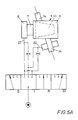
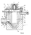
- FIGS. 5 to 7 The embodiment of FIGS. 5 to 7 is characterized by pneumatic means for threading.
- the conical roller 33 of the yarn feeder 1 is firmly connected to the shaft 2 and the turbine wheel 3.
- the shaft 2 is rotatably supported between the conical roller 33 and the turbine wheel 3 by bearings 4 in the housing 5.
- the housing 5 consists of a trigger housing 6, a bearing housing 7 and a drive housing 8.
- a conical bore 9 is made in the trigger housing 6 and ends in a cylindrical bore 10.
- the conical bore surrounds the conical roller 33 with a narrow gap 11.
- the gap 11 is e.g. 1 mm wide.
- a groove 12 is cut, which is helical.
- the inlet end 13 of the groove 12 is aligned with the thread inlet channel 14.
- the outlet end 15 of the groove 12 is aligned with the thread suction channel 16.
- the thread inlet channel 14 can be filled with injector nozzles 17, which are fed via the air connection 18 and the ring channel 19.
- the injector 17, 18, 19 generates a negative pressure in the entrance of the thread inlet channel 14, so that a supplied thread end 20 is sucked in here.
- a suction device 24 is arranged behind the roller 1.
- the thread suction channel 16 is filled with the injector nozzles 21, which also point in the thread running direction and which are fed through the air inlet tube 22 and the ring channel 23.
- the injector 21, 22, 23 generates or supports the suction air flow in the channel strip, which consists of thread inlet channel 14, groove 12 and thread suction channel 16.
- the turbine wheel 3 is fixedly attached to the shaft end 2, which faces away from the conical roller 1.
- the turbine wheel 3 consists of the two end disks 25, between which the turbine blades 26 (section according to FIG. 7) are fastened, e.g. by welding.
- One end disk 25 of the turbine wheel 3 is firmly seated on the shaft 2.
- the turbine housing 8 forms an annular channel 80 with and around the turbine wheel 3.
- the compressed air channel 27 opens into this annular channel.
- the compressed air channel 27 is directed essentially tangentially into the annular channel. Its orientation and the shape of its mouth is generally known in the construction of compressed air turbines and is not described in more detail here.
- the required air pressure can build up in the ring channel 80.
- the turbine wheel can be driven at speeds of up to 10,000 rpm.
- the blades 26 of the turbine wheel 3 leave the outflow channel 28 free in the center of the turbine wheel.
- the outflow channel is closed on the bearing side by an end plate 25.
- the outflow channel 18 opens to the free end of the shaft 2 in the axial air outlet 29 of the housing, the end plate 25 also having a correspondingly large hole.
- the groove 12 in the jacket of the conical bore 9 is particularly advantageous for threading, in particular for safety in catching and the reproducibility of thread catching is.
- the groove creates a flow field of high energy in the cross-sectional area of the groove, the flow direction of which is well defined by the groove geometry. This ensures that the thread is conveyed from the thread inlet channel 14 and the inlet end 13 of the groove to the outlet end 15 of the groove and thus into the thread suction channel 16.
- the compressed air channel 27 is pressurized with compressed air and the turbine wheel 3 with the shaft 2 and the winding body 1 is thereby rotated until the peripheral speed of the godet 30 is reached.
- the injector nozzles 17 and 21 are charged with compressed air via air connection lines 18 and in particular 22. This creates a suction flow at the entrance of the thread inlet channel 14, which continues as a vortex flow around the roller 1 and as an air flow in the outlet channel 16.
- the air speed is higher than the thread speed.
- the thread is wound in a swirl of air around the cone roller 1 in a fraction of a second. It is inevitable that the thread comes into contact with the cone roller. Now the thread is drawn off by frictional contact with the conical roller 1.
- the peripheral speed of the conical roller 1 in the area of the thread inlet plane is at least equal to the thread speed specified by the feed mechanism 30.
- the peripheral speed of the conical roller 1 is also greater in the area of the thread outlet (groove end 15) than the thread speed. Therefore, the cone exerts considerable friction on the thread. This frictional force is sufficient to pull the thread with such high thread tension subtract from the lowering unit 30 in such a way that it can be applied to the supply unit 30 without a thread winder forming on the supply unit 30.
- 5A shows a manual sequence control.
- the air supply is switched off without operation (position I).
- position II of the valve set by hand only the air turbine is supplied with compressed air via line 27.
- the valve is then switched to a further operating position III.
- position III the suction device 24 is acted upon via line 22 with the essential part of the available compressed air quantity, while the turbine now receives a reduced quantity via a throttle. It is also possible to completely shut off the supply line to the turbine via the throttle.
- the valve is switched so that the suction device 24 is only supplied with compressed air via another throttle, while the essential part of the compressed air is supplied to the turbine.
- the rotation of the roller 1 contributes in particular to the formation of eddies and the thread transport with axial feed from the thread inlet to the thread outlet.
- the thread inlet can lie on the same normal plane as the thread outlet.
- the risk of winder formation is somewhat coarser.
- Fin axial feed is achieved in particular by _ thread inlet channel, as is also shown in FIG. 5 and thread suction channel are axially offset from one another and that the suction device lies behind the roller, that is to say in the thread suction channel, so that a defined suction flow results from the thread inlet into the thread outlet. This reduces the risk of winders.
- the air flow in the channel strip consisting of thread inlet duct 14, groove 12 and thread suction duct 16 can be substantially reduced, since the thread conveyance now takes place essentially by frictional contact with the conical roller 1.
- the cone roller has a continuously decreasing diameter towards its free end in the entire area that comes into contact with the thread.
- the coefficient of friction and the cone angle are coordinated so that the thread cannot be held on the surface by self-locking, but in any case slips when it is under the corresponding thread tension. For this reason, it is excluded that a winder forms on the cone roller 1. Fin winder will automatically tend to slip towards the free end of the roller. The winder must also pass the groove end 15 or the entrance of the thread suction channel 16. Most winders are therefore already caught here and suctioned through the thread suction channel 16 by means of the injectors 21.
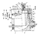
- FIGS. 8 and 9. 8 is constructed as follows:
- the housing 5 has a bore which is conical in its lower part 9.
- the housing 5 is closed on its upper face by a cover 77.
- the cover 77 is connected to the housing by screws 74.
- a socket 8 of the cover 77 which is concentric with the pipe 9 in the housing 5, there is the position 4 of the winding body 1.
- the winding body 1 is part of a structural unit with the shaft 2, the turbine wheel 3 and the winding body 1.
- the shaft 2 is firmly connected to an end face 25 of the turbine wheel and is freely rotatably supported in the bushing 8 by two ball bearings.
- the turbine wheel 3 consists of the two end disks 25, between which the turbine blades 26 (section according to FIG. 7) are fastened, for example by welding.
- the winding body 1 is seated on one end disk 25 of the turbine wheel 3.
- the winding body 1 is a bonus which has essentially the same conicity as the bore 9 in the housing 5.
- the winding body forms an annular thread chamber 9 in this bore, which also tapers conically towards the free end of the winding body 1 with respect to its mean diameter.
- the cone angle of the winding body 1 is smaller than the cone angle of the bore 9.
- the width of the thread chamber 9 also tapers towards the end of the winding body 1.
- the winding body 1 has a bead 38 which forms a narrow channel in the form of an annular nozzle 79 with the cylindrical part of the bore in the housing 5.
- the upper cylindrical part of the bore in the housing 5 forms an annular channel 80 with and around the turbine wheel 3.
- the compressed air channel 27 opens into this annular channel 80.
- the compressed air channel 27 is directed essentially tangentially into the annular channel. Its orientation and the shape of its mouth is generally known in the construction of compressed air turbines and is not described in more detail here. Since the bead 38 of the winding body 1 of the cylindrical chamber wall in the housing 5 forms an annular nozzle with strong throttle resistance, the required air pressure can build up in the annular channel 80.
- the turbine wheel can be driven at speeds of up to 10,000 rpm.
- the blades 26 of the turbine wheel leave the outflow channel 28 free in the center of the turbine wheel.
- the outflow channel is closed on the bearing side by the end plate 25.
- the outflow channel 28 opens to the free end of the winding body 1 in its central channel 81, the other end plate 25 also having a correspondingly large hole.
- the pin 73 in the center of the turbine wheel 3 is shaped such that the air passing between the blades 26 is deflected in the direction of the central channel 81 in the winding body 1.
- the thread inlet 14 opens into the housing bore 5.
- the thread inlet 14 lies essentially on a tangential plane of the winding body 1.
- the thread inlet 14 can lie on a normal plane of the winding body 1.
- the thread inlet channel 14 can also be arranged such that it crosses the axis of the winding body 1 at an obtuse angle in the projection according to FIG. 8.
- the thread conveyed by thread inlet 14 can also have a movement component in the direction of the free end of the winding body 1.
- An end piece 68 is attached to the housing 5.
- the thread chamber 9 ends in a conical, rounded blind hole 69.
- the end piece 68 also has a wide incision 70 on its edge.
- the incision is rounded towards the blind hole and, in the installed state, lies in a normal plane in the region of the thinnest end of the rotating body 1.
- the incision 70 is aligned with the suction channel 16, which is flanged to the housing end piece 68 and is fitted with injectors 21.
- the cross section of the suction channel 16 is essentially adapted to the adjacent cross section of the incision 70 with which the incision 70 opens into the suction channel 16.
- the windings collect and as a result of the air flow coming through the central channel 81 _ starting from the turbine wheel 3 _ and as a result of the air flow in the filament chamber 9, the vault falling from the rotating body 1 is not only collected in the blind hole 69, but also due to the air flow to the suction channel 16 at the same time also promoted in the direction of the incision 70 and the suction channel 16.
- the bulge is detected by the injectors 21 and placed under a certain tension. This causes the vault to pull out into a smooth thread again. Since the suction channel 16 lies in a normal plane which intersects the rotary body in the region of its thinnest, the thread is now drawn off tangentially from the rotary body, as indicated by line 71.
- the suction device receives only so much compressed air that a sufficiently high thread tension 52 of the thread running off the roller 1 is generated in order to generate the thread tension resulting from the looping in the thread running towards the roller 1.
- the thread turns which are formed in the normal plane of the thread inlet in the rotating body, continue to slide due to the conicity, the low friction and the air flow on the cone.
- the thread tension in the reverberation of the thread inlet 14 can be adjusted by setting the speed and the torque of the rotating body 1 as desired and so high that a godet (not shown here) can be applied without the winder being formed on the godet.
- the turns slipping on the bonus lose their thread tension, so that the thread can be easily conveyed in the suction channel 16.
- the suction flow required for this can be generated with the injectors 21 without any particular effort.
- the thread pulling device is also suitable for storing a thread in the form of a fleece, felt or as waste.
- FIG. 9 essentially corresponds to the embodiment according to FIG. 8 with regard to the thread guidance.
- This thread take-off device can be used in particular for waste disposal or for the further processing of the thread.
- the housing 5 has a wide slot 61 on its circumference. This slot extends over part of the circumference with such a central angle that the thread can be placed through this slot 61 with a wrap around the winding body 1.
- a casing 62 is displaceable on the housing 5. The jacket is pressed into its outer right position by spring 63. The force of the springs can be adjusted by screw 64.
- the jacket 62 has the thread inlet connector 14 on its circumference.
- the thread inlet nozzle is directed essentially tangentially to the circumference of the rotating body 1 and its thread channel also extends through the jacket 62.
- the thread inlet nozzle 14 can be populated with the indicated injectors 18 which cause a suction flow in the inlet nozzle.
- the thread inlet connector 14 is designed so that it lies in the outer right position, which is shown in Fig. 9, substantially on the normal plane and the working area of the winding body, which has the largest diameter.
- the thread guide 65 is fastened to the jacket 62.
- the thread 59 coming from a spinneret and to be applied to the take-off unit 60 or coming from the take-off unit 60 is tensioned between the fixed thread guides 66 and 67 on the one hand and the thread guide 65 movable with the jacket 62 on the other hand.
- the jacket 62 is shifted to the left against the force of the spring 63 as the thread tension increases.
- Fixed means that the thread guides are immovable with respect to the housing 5 of the thread take-off device.
- Threading in circumferential contact with the rotating body is facilitated if the jacket 62 is moved to the left against the spring force 63 in FIG. 9, so that the thread initially runs onto a smaller diameter of the rotating body 1. After catching, the jacket is released into its right extreme position predetermined by the spring 63 and a stop.
- the thread turns on the rotating body continue to slide due to the taper and the low friction, the thread tension above the thread inlet 14 not only by adjusting the speed of the rotating body 1, but also by shifting the jacket 62 and thus the point of the thread on the roller 1 as desired and can be set so high that the thread can be placed on the delivery godet 30 running at a constant, high peripheral speed without 30 winder being produced on the delivery godet.
- the turns slipping on the cone lose their thread tension, so that the thread, e.g. is guided into the waste or onto a collection or transport container in which the suction channel 16 can easily be conveyed.
- the air flow required for this can be generated with the injectors 21 without any particular effort.
- the thread can also be withdrawn from another delivery plant.
- the thread pulling device can regulate the thread tension between the Delivery godet 30 and the thread take-off device are used.
- the thread is placed around the thread guides 66, 67, 65 in the manner shown, which serve to measure the thread tension.
- the width of the slot 61 determines the working area in which the point of the thread can be moved onto the winding body 1.
- the thread is wound on the winding body 1 at a higher or lower winding speed.
- the thread tension can be controlled and regulated by adjusting the position of the jacket 62.
- the thread guide 65 and thus also the jacket 62 are shifted to the left.
- the thread inlet connector 14 lies on a normal plane with a smaller diameter.
- the winding speed drops and the thread tension decreases. There is therefore an equilibrium state between the thread tension on the one hand and the spring force 63.
- the target value of the thread tension can be specified by setting the spring force 63. This ensures that the thread tension, which is given to the thread by the take-off device, is always sufficient to avoid winders on the take-off mechanism 60 or to exert constant thread forces on the thread to influence the thread properties.
Landscapes
- Engineering & Computer Science (AREA)
- Textile Engineering (AREA)
- Mechanical Engineering (AREA)
- Spinning Methods And Devices For Manufacturing Artificial Fibers (AREA)
Claims (17)
Applications Claiming Priority (8)
| Application Number | Priority Date | Filing Date | Title |
|---|---|---|---|
| DE3613040 | 1986-04-17 | ||
| DE19863613040 DE3613040A1 (de) | 1986-04-17 | 1986-04-17 | Fadenabzuggeraet |
| DE3614864 | 1986-05-02 | ||
| DE3614864 | 1986-05-02 | ||
| DE3621139 | 1986-06-24 | ||
| DE3621139 | 1986-06-24 | ||
| DE19863641849 DE3641849A1 (de) | 1986-12-08 | 1986-12-08 | Fadenabzuggeraet |
| DE3641849 | 1986-12-08 |
Publications (3)
| Publication Number | Publication Date |
|---|---|
| EP0241850A2 EP0241850A2 (fr) | 1987-10-21 |
| EP0241850A3 EP0241850A3 (en) | 1988-07-27 |
| EP0241850B1 true EP0241850B1 (fr) | 1991-07-03 |
Family
ID=27433574
Family Applications (1)
| Application Number | Title | Priority Date | Filing Date |
|---|---|---|---|
| EP87105166A Expired - Lifetime EP0241850B1 (fr) | 1986-04-17 | 1987-04-08 | Dispositif de tirage de fil |
Country Status (3)
| Country | Link |
|---|---|
| US (1) | US4817880A (fr) |
| EP (1) | EP0241850B1 (fr) |
| DE (1) | DE3771107D1 (fr) |
Families Citing this family (21)
| Publication number | Priority date | Publication date | Assignee | Title |
|---|---|---|---|---|
| DE3737960A1 (de) * | 1987-11-07 | 1989-05-24 | Barmag Barmer Maschf | Fadenabzuggeraet |
| ES2035177T3 (es) * | 1987-07-30 | 1993-04-16 | B A R M A G Ag | Aparato de desarrollo de hilo. |
| DE3825272C2 (de) * | 1987-08-03 | 1994-02-24 | Barmag Barmer Maschf | Verfahren zum Anspinnen eines Polyamidfadens |
| US4880177A (en) * | 1987-11-07 | 1989-11-14 | Barmag, Ag | Yarn withdrawal apparatus |
| US5110061A (en) * | 1990-12-03 | 1992-05-05 | Berry Roger P | Pneumatic reel fiber pay out system |
| DE4104863A1 (de) * | 1991-02-16 | 1992-08-20 | Fritz Stahlecker | Vorrichtung zum zwischenspeichern eines fadens |
| US5475907A (en) * | 1994-08-12 | 1995-12-19 | American Line Corporation | Apparatus and method for forming coils of yarn and for heat setting the same |
| EP0937672A1 (fr) * | 1998-02-20 | 1999-08-25 | E.I. Du Pont De Nemours And Company | Procédé et dispositif pour couper une bande, alimenter ladite bande vers une unité de production et l'introduire dans ladite unité |
| US6370747B1 (en) * | 2000-09-13 | 2002-04-16 | Owens Corning Fiberglas Technology, Inc. | Method and apparatus for the bulk collection of texturized strand |
| JP4005504B2 (ja) * | 2000-11-09 | 2007-11-07 | バルマーク アクチエンゲゼルシヤフト | テクスチャード機械及び走行糸の布設法 |
| US6830172B2 (en) | 2001-10-26 | 2004-12-14 | Kimberly-Clark Worldwide, Inc. | Apparatus and method for feeding string |
| US6669130B2 (en) * | 2001-10-26 | 2003-12-30 | Kimberly-Clark Worldwide, Inc. | Feeding string |
| US8474115B2 (en) * | 2009-08-28 | 2013-07-02 | Ocv Intellectual Capital, Llc | Apparatus and method for making low tangle texturized roving |
| JP5642441B2 (ja) * | 2010-07-13 | 2014-12-17 | Tmtマシナリー株式会社 | 紡糸巻取装置への糸掛け方法、紡糸巻取装置、及びサクションガン |
| TW201221256A (en) * | 2010-11-23 | 2012-06-01 | Ind Tech Res Inst | Transmitting wire module |
| JP2014125349A (ja) * | 2012-12-27 | 2014-07-07 | Murata Mach Ltd | 糸貯留装置及び紡績ユニット |
| JP6043366B2 (ja) | 2012-12-28 | 2016-12-14 | 株式会社クラレ | 延伸装置および延伸方法 |
| US10071871B2 (en) * | 2013-03-14 | 2018-09-11 | Gpcp Ip Holdings Llc | Air knife configured to improve rolling of paper product |
| EP3753885A1 (fr) * | 2019-06-19 | 2020-12-23 | Heberlein AG | Appareil d'aspiration pour une machine textile, machine textile dotée d'un dispositif d'aspiration, utilisation de deux éléments de cyclone et procédé d'aspiration de fils |
| EP3838384A1 (fr) * | 2019-12-21 | 2021-06-23 | Gambro Lundia AB | Transferts de faisceaux de fibres |
| US11214450B1 (en) * | 2021-03-11 | 2022-01-04 | Cciip Llc | Method of proofing an innerduct/microduct and proofing manifold |
Family Cites Families (25)
| Publication number | Priority date | Publication date | Assignee | Title |
|---|---|---|---|---|
| US1962029A (en) * | 1932-06-21 | 1934-06-05 | Dunlop Rubber Co | Supplying thread under extension, for example in covering machines |
| US2350182A (en) * | 1941-12-20 | 1944-05-30 | Du Pont | Yarn production |
| US2539978A (en) * | 1949-04-25 | 1951-01-30 | American Enka Corp | Drying yarn |
| CH289657A (fr) * | 1949-06-02 | 1953-03-31 | Lebocey Machines | Machine de bonneterie munie d'un dispositif autorégulateur pour la délivrance du fil d'alimentation. |
| US2885257A (en) * | 1951-04-18 | 1959-05-05 | Filament drawing mechanism | |
| US2744399A (en) * | 1954-06-18 | 1956-05-08 | Stibbe G & Co Ltd | Yarn feeding mechanism for knitting machines |
| GB861140A (en) * | 1957-10-25 | 1961-02-15 | Ici Ltd | Treatment of yarns |
| US2929179A (en) * | 1959-02-24 | 1960-03-22 | Willard S George | Strand curling method and apparatus |
| US3083924A (en) * | 1959-09-11 | 1963-04-02 | Textile Devices Corp | Yarn furnishing device |
| BE629015A (fr) * | 1962-03-01 | |||
| US3272416A (en) * | 1964-09-16 | 1966-09-13 | Du Pont | Yarn handling mechanism |
| DE1220637B (de) * | 1965-01-23 | 1966-07-07 | Bayer Ag | Vorrichtung zum aufeinanderfolgenden Abziehen, Messen, Knaeueln und Abtrennen eines Fadens |
| US3564958A (en) * | 1967-07-17 | 1971-02-23 | Leesona Corp | Yarn handling apparatus |
| DE1966159B2 (de) * | 1968-10-14 | 1972-09-28 | Fadenspeicher- und -liefervorrichtung fuer textilmaschinen | |
| US3666431A (en) * | 1969-11-10 | 1972-05-30 | Owens Corning Fiberglass Corp | Apparatus for advancing glass fibers |
| US3706407A (en) * | 1970-10-07 | 1972-12-19 | Bouligny Inc R H | Piddler mechanism for strand material |
| FR2200834A5 (fr) * | 1972-09-25 | 1974-04-19 | Rhone Poulenc Textile | |
| JPS5244661Y2 (fr) * | 1973-01-12 | 1977-10-11 | ||
| BR7601196A (pt) * | 1975-03-07 | 1976-09-14 | Barmag Barmer Maschf | Dispositivo transportador de cabo de fibras sinteticas,e,processo de sua operacao |
| DE2633474C3 (de) * | 1976-07-26 | 1980-06-04 | Franz Fourne | Vorrichtung zum Ablegen eines fadenförmigen Gutes bzw. eines Fadenkabels in einen Behälter o.dgl. endlos, oder in Form von Teilen begrenzter Länge |
| DE2648621C3 (de) * | 1976-10-27 | 1981-11-26 | Palitex Project-Company Gmbh, 4150 Krefeld | Doppeldraht-Zwirnmaschine |
| BE890315A (fr) * | 1981-09-11 | 1982-01-04 | Inventa Ag | Procede de tirage et de depot d'une matiere sans fin semblable a un cable, un cordon ou un filament |
| DE3324947C1 (de) * | 1983-06-16 | 1984-10-25 | Bernd Dipl-Ing Scheffel | Fadenspeichervorrichtung für Webmaschinen und Verfahren zu deren Betrieb |
| US4638955A (en) * | 1984-03-27 | 1987-01-27 | Barmag Barmer Maschinenfabrik Ag | Yarn handling apparatus for winding machine |
| DE3632338A1 (de) * | 1985-09-27 | 1987-05-27 | Barmag Barmer Maschf | Einrichtung zur speicherung und beseitigung von fadenabfall |
-
1987
- 1987-04-08 EP EP87105166A patent/EP0241850B1/fr not_active Expired - Lifetime
- 1987-04-08 DE DE8787105166T patent/DE3771107D1/de not_active Expired - Fee Related
- 1987-04-14 US US07/038,334 patent/US4817880A/en not_active Expired - Fee Related
Also Published As
| Publication number | Publication date |
|---|---|
| DE3771107D1 (de) | 1991-08-08 |
| EP0241850A2 (fr) | 1987-10-21 |
| US4817880A (en) | 1989-04-04 |
| EP0241850A3 (en) | 1988-07-27 |
Similar Documents
| Publication | Publication Date | Title |
|---|---|---|
| EP0241850B1 (fr) | Dispositif de tirage de fil | |
| EP0565878B1 (fr) | Dispositif d'aspiration pour une multitude de fils continus | |
| DE60009402T2 (de) | Spinnvorrichtung und Spinnverfahren | |
| DE2615909A1 (de) | Verfahren zum fangen, abtrennen und ansetzen eines fadens und eine vorrichtung zur durchfuehrung des verfahrens | |
| DE2533655A1 (de) | Verfahren und vorrichtung zum beginnen, unterbrechen und anhalten des spinnvorganges eines mit einem band umwundenen gesponnenen garns | |
| DE2648621B2 (de) | Doppeldraht-Zwirnmaschine | |
| EP3153612A1 (fr) | Procédé de préparation d'un penne pour commencer à filer sur un dispositif de filature à rotor d'une machine à filer à rotor et machine à filer à rotor | |
| EP0365472B1 (fr) | Dispositif pour enfiler un fil dans un métier à tisser | |
| DE60103721T2 (de) | Anspinnverfahren und Anspinnvorrichtung für eine Spinnmaschine | |
| EP0162367B2 (fr) | Procédé et dispositif pour la préparation de l'extrémité de fil pour la remise en route d'une machine à bout libéré | |
| EP0230974B1 (fr) | Dispositif de tirage de fil | |
| CH674855A5 (fr) | ||
| EP3546406B1 (fr) | Procédé de formation d'une boucle de fil et de séparation d'une section de fil à utiliser et d'une section de fil à évacuer et unité de rouleaux presseurs | |
| DE2817478C2 (de) | Vorrichtung zum Einführen mindestens eines Fadens in eine Texturierdüse | |
| DE3430369A1 (de) | Verfahren und vorrichtung zur herstellung eines verbaenderten gesponnenen garnes | |
| EP1529129A1 (fr) | Machine de texturation | |
| WO1990011396A1 (fr) | Dispositif pour passer un fil dans le magasin de fils de trame d'un metier automatique | |
| EP1112218B1 (fr) | Machine de texturation permettant de texturer et d'enrouler un fil | |
| DE4225349A1 (de) | Vorrichtung zum Entfernen von Endwindungen, insbesondere Fußwindungen und/oder Fadenenden im Bereich des Hülsenfußes von Spinnkopsen | |
| DE3146263A1 (de) | "verfahren und spulmaschine zum aufwickeln eines mit hoher geschwindigkeit kontinuierlich angelieferten fadens auf einer spule" | |
| CH438112A (de) | Vorrichtung zum Erfassen des Fadenanfanges eines Kopses | |
| EP0018577B1 (fr) | Procédé et dispositif pour mettre en place automatiquement un fil sur une bobine | |
| DE4115339B4 (de) | Spulhülse | |
| DE2331114A1 (de) | Stufenloser energieabbau eines fadenkabels | |
| DE2544652C2 (de) | Wartungsvorrichtung für Doppeldrahtzwirnmaschinen |
Legal Events
| Date | Code | Title | Description |
|---|---|---|---|
| PUAI | Public reference made under article 153(3) epc to a published international application that has entered the european phase |
Free format text: ORIGINAL CODE: 0009012 |
|
| AK | Designated contracting states |
Kind code of ref document: A2 Designated state(s): CH DE FR GB IT LI |
|
| PUAL | Search report despatched |
Free format text: ORIGINAL CODE: 0009013 |
|
| AK | Designated contracting states |
Kind code of ref document: A3 Designated state(s): CH DE FR GB IT LI |
|
| 17P | Request for examination filed |
Effective date: 19880730 |
|
| 17Q | First examination report despatched |
Effective date: 19900307 |
|
| ITF | It: translation for a ep patent filed | ||
| GRAA | (expected) grant |
Free format text: ORIGINAL CODE: 0009210 |
|
| AK | Designated contracting states |
Kind code of ref document: B1 Designated state(s): CH DE FR GB IT LI |
|
| ET | Fr: translation filed | ||
| REF | Corresponds to: |
Ref document number: 3771107 Country of ref document: DE Date of ref document: 19910808 |
|
| GBT | Gb: translation of ep patent filed (gb section 77(6)(a)/1977) | ||
| PLBE | No opposition filed within time limit |
Free format text: ORIGINAL CODE: 0009261 |
|
| STAA | Information on the status of an ep patent application or granted ep patent |
Free format text: STATUS: NO OPPOSITION FILED WITHIN TIME LIMIT |
|
| 26N | No opposition filed | ||
| PGFP | Annual fee paid to national office [announced via postgrant information from national office to epo] |
Ref country code: FR Payment date: 19950322 Year of fee payment: 9 |
|
| PGFP | Annual fee paid to national office [announced via postgrant information from national office to epo] |
Ref country code: GB Payment date: 19950329 Year of fee payment: 9 |
|
| PGFP | Annual fee paid to national office [announced via postgrant information from national office to epo] |
Ref country code: CH Payment date: 19950508 Year of fee payment: 9 |
|
| PG25 | Lapsed in a contracting state [announced via postgrant information from national office to epo] |
Ref country code: GB Effective date: 19960408 |
|
| PG25 | Lapsed in a contracting state [announced via postgrant information from national office to epo] |
Ref country code: LI Effective date: 19960430 Ref country code: CH Effective date: 19960430 |
|
| PGFP | Annual fee paid to national office [announced via postgrant information from national office to epo] |
Ref country code: DE Payment date: 19960612 Year of fee payment: 10 |
|
| GBPC | Gb: european patent ceased through non-payment of renewal fee |
Effective date: 19960408 |
|
| REG | Reference to a national code |
Ref country code: CH Ref legal event code: PL |
|
| PG25 | Lapsed in a contracting state [announced via postgrant information from national office to epo] |
Ref country code: FR Effective date: 19961227 |
|
| REG | Reference to a national code |
Ref country code: FR Ref legal event code: ST |
|
| PG25 | Lapsed in a contracting state [announced via postgrant information from national office to epo] |
Ref country code: DE Free format text: LAPSE BECAUSE OF NON-PAYMENT OF DUE FEES Effective date: 19980101 |
|
| PG25 | Lapsed in a contracting state [announced via postgrant information from national office to epo] |
Ref country code: IT Free format text: LAPSE BECAUSE OF NON-PAYMENT OF DUE FEES;WARNING: LAPSES OF ITALIAN PATENTS WITH EFFECTIVE DATE BEFORE 2007 MAY HAVE OCCURRED AT ANY TIME BEFORE 2007. THE CORRECT EFFECTIVE DATE MAY BE DIFFERENT FROM THE ONE RECORDED. Effective date: 20050408 |