EP0241850B1 - Device for drawing off a thread - Google Patents
Device for drawing off a thread Download PDFInfo
- Publication number
- EP0241850B1 EP0241850B1 EP87105166A EP87105166A EP0241850B1 EP 0241850 B1 EP0241850 B1 EP 0241850B1 EP 87105166 A EP87105166 A EP 87105166A EP 87105166 A EP87105166 A EP 87105166A EP 0241850 B1 EP0241850 B1 EP 0241850B1
- Authority
- EP
- European Patent Office
- Prior art keywords
- thread
- supply mechanism
- roller
- suction
- channel
- Prior art date
- Legal status (The legal status is an assumption and is not a legal conclusion. Google has not performed a legal analysis and makes no representation as to the accuracy of the status listed.)
- Expired - Lifetime
Links
Images


Classifications
-
- D—TEXTILES; PAPER
- D04—BRAIDING; LACE-MAKING; KNITTING; TRIMMINGS; NON-WOVEN FABRICS
- D04H—MAKING TEXTILE FABRICS, e.g. FROM FIBRES OR FILAMENTARY MATERIAL; FABRICS MADE BY SUCH PROCESSES OR APPARATUS, e.g. FELTS, NON-WOVEN FABRICS; COTTON-WOOL; WADDING ; NON-WOVEN FABRICS FROM STAPLE FIBRES, FILAMENTS OR YARNS, BONDED WITH AT LEAST ONE WEB-LIKE MATERIAL DURING THEIR CONSOLIDATION
- D04H3/00—Non-woven fabrics formed wholly or mainly of yarns or like filamentary material of substantial length
- D04H3/02—Non-woven fabrics formed wholly or mainly of yarns or like filamentary material of substantial length characterised by the method of forming fleeces or layers, e.g. reorientation of yarns or filaments
- D04H3/03—Non-woven fabrics formed wholly or mainly of yarns or like filamentary material of substantial length characterised by the method of forming fleeces or layers, e.g. reorientation of yarns or filaments at random
-
- B—PERFORMING OPERATIONS; TRANSPORTING
- B65—CONVEYING; PACKING; STORING; HANDLING THIN OR FILAMENTARY MATERIAL
- B65H—HANDLING THIN OR FILAMENTARY MATERIAL, e.g. SHEETS, WEBS, CABLES
- B65H51/00—Forwarding filamentary material
- B65H51/20—Devices for temporarily storing filamentary material during forwarding, e.g. for buffer storage
- B65H51/22—Reels or cages, e.g. cylindrical, with storing and forwarding surfaces provided by rollers or bars
-
- B—PERFORMING OPERATIONS; TRANSPORTING
- B65—CONVEYING; PACKING; STORING; HANDLING THIN OR FILAMENTARY MATERIAL
- B65H—HANDLING THIN OR FILAMENTARY MATERIAL, e.g. SHEETS, WEBS, CABLES
- B65H54/00—Winding, coiling, or depositing filamentary material
- B65H54/86—Arrangements for taking-up waste material before or after winding or depositing
- B65H54/88—Arrangements for taking-up waste material before or after winding or depositing by means of pneumatic arrangements, e.g. suction guns
-
- D—TEXTILES; PAPER
- D01—NATURAL OR MAN-MADE THREADS OR FIBRES; SPINNING
- D01D—MECHANICAL METHODS OR APPARATUS IN THE MANUFACTURE OF ARTIFICIAL FILAMENTS, THREADS, FIBRES, BRISTLES OR RIBBONS
- D01D7/00—Collecting the newly-spun products
-
- B—PERFORMING OPERATIONS; TRANSPORTING
- B65—CONVEYING; PACKING; STORING; HANDLING THIN OR FILAMENTARY MATERIAL
- B65H—HANDLING THIN OR FILAMENTARY MATERIAL, e.g. SHEETS, WEBS, CABLES
- B65H2701/00—Handled material; Storage means
- B65H2701/30—Handled filamentary material
- B65H2701/31—Textiles threads or artificial strands of filaments
Definitions
- the invention relates to a thread take-off device for pulling a continuously running thread with a suction device which removes the thread in an air stream.
- the invention relates to methods for applying a freshly spun chemical thread coming from the spinneret to rapidly rotating machine parts.
- the invention solves the problem of designing the so-called suction guns or other suction devices in such a way that they can apply sufficiently high thread tensile forces even at high thread speeds of more than 4,000 m / min.
- Suction guns or other suction devices serve the purpose of pulling off continuously occurring threads, in particular man-made fibers during the business interruption, for example during the bobbin change in a man-made fiber spinning machine, and feeding them to the waste.
- the thread is subjected to a strong air flow in these suction pistols.
- the limit of the possibility of using such devices is at thread speeds of approx. 4000 m / min (65 to 70 m / s). It becomes particularly impossible to apply the necessary thread tensions when the thread is to be placed on godets or winding machines and / or is conveyed by means of godets. There is a risk that the thread will form a winder on the godet / winding machine due to insufficient thread tension.
- the compressors or are required because of the very high power requirement Vacuum pumps represent a significant cost factor, although these machines are only needed for short periods in the event of business interruptions.
- the threading device is arranged directly upstream of the suction device.
- This thread feed mechanism consists of at least one driven roller to be looped by the thread.
- the suction mouth is arranged in the immediate vicinity of the surface of the roll in the thread path behind the roll and preferably on an outlet tangent thereof.
- the invention further provides measures by which it is ensured that the thread does not form any winders on the thread feed mechanism.
- this two rollers arranged at a short distance from one another and rotating in the same direction are provided, at least one of which can be driven and the roller axes of which are interleaved or form an acute angle with one another.
- the thread is guided over this feed mechanism in such a way that it runs onto the rollers in the area of the wide center distance and that the suction device is arranged in the area of the small roller distance.
- the suction device can connect to the lower works substantially in the axial direction or encompass the end of the supply works, whereby a thread guide must be present which prevents the thread from unwinding again overhead from the supply works.
- the suction device can be arranged transversely to the roll axes, so that the thread is drawn off tangentially from the rolls.
- the formation of the winder is avoided in that the thread feed mechanism is formed from only one roll, which is of conical design.
- the roll is cantilevered at its thick end, so that any curlers that may form always slide off towards the thin end and can be removed there.
- a constant, axial feed is effected, so that _ as with the delivery unit with two rollers, the axes of which are interlaced with one another, _ several turns are not superimposed.
- the thread take-off device according to this invention can be mounted as a stationary unit, in which case mechanical or pneumatic means for applying the thread to the thread feed mechanism must be provided at the same time. Above all, however, the thread take-off device can be designed as a portable handling device, comparable to the previous suction pistols.
- the following method is proposed, in particular in chemical fiber spinning systems: the thread which is produced by the spinneret at a relatively low speed is first caught by the suction device, so that the thread is drawn off with the tensile force that can be generated by the suction device alone. Now the handling device is pivoted in such a way that the roller axis or roller axes traverse the thread path once or several times in a wobbling movement. As a result, the thread forms one or more loops on the roll or rolls.
- the handling device must be held in this way at the end of this process, or the thread must be inserted in a thread guide located on the handling device at the end of this process. be that it tapers to the roles or the role substantially tangentially. In this way it is avoided that the point of run-up of the thread migrates to the feed mechanism in the axial direction.
- the thread pulling device can now exert such a high thread tension on the thread that the thread can be applied to high-speed machine parts such as godets and / or winding devices without the risk of winder formation.
- the thread feed mechanism When the thread is applied to the thread feed mechanism, it is drawn off with greater tensile force, the tensile force corresponding on the one hand to the torque of the drive motor and on the other hand to the number of wraps.
- the torque characteristics of the motor on the one hand and the number of wraps must be coordinated so that there is no thread breakage.
- the suction device is now only used for the purpose of applying a low tensile force in the thread end running off. This tensile force in the running thread end only has to be so great that a sufficient tensile force in the incoming thread end is induced by wrap friction. On the other hand, only a low tensile force of the running thread end can be compensated for by additional looping.
- An additional possibility for setting and / or regulating the thread tension is given in that the point at which the thread runs up is axially adjustable and in that the thread feed mechanism consists of a conical roller.
- Mechanical devices for thread application can be designed such that the thread pulling device is pivoted about the thread axis after the thread has been caught in the suction device.
- the invention proposes a mechanically simple and safe-acting application device.
- This consists of a thread guide that bypasses the thread feed mechanism on an envelope and thereby traverses the thread path in the area of the suction device.
- the thread guide preferably also gives the thread an axial feed.
- it can be a flyer-like thread guide that is coaxial or parallel to the roll axis or _ in a yarn feed unit that consists of two rollers _ is pivotally mounted in a plane between the roller axes.
- the axial feed can be effected in that the flyer is mounted in a thread or in that the thread guide located on its outer arm is of helical design.
- the invention provides pneumatic threading means which cooperate with the suction device.
- the air flow conveying the thread is guided tangentially on and in a vortex, a roller and then subtracted tangentially.
- the roller is constantly driven with the direction of rotation of the vortex.
- the air flow hits the roller circumference in a normal plane in the area of the thicker end (thread inlet plane).
- the peripheral speed is at least equal to the thread speed.
- the air vortex then continues towards the thinner end of the conical roller.
- the roller for generating the air vortex is surrounded by a flow channel which forms a narrow gap with the roller and is so wide open to the roller that the thread can leave the flow channel.
- the flow channel can be a helically curved, slotted tube.
- the inner shell of this housing forms a narrow gap with the roller.
- the gap width is dimensioned so that the thread on the roller can also form a small winder.
- In the inner casing is a helical flow channel Cut groove that extends around the roller with at least half a turn.
- Thread inlet channel and thread outlet channel which penetrate the housing, open in front of and behind this groove, respectively.
- the channels are preferably aligned with the groove ends.
- the roller can in turn be conical in order to achieve an axial advance of the thread turns.
- the interior of the housing can also be conical.
- Conical rollers also have the advantage that the thread tension is automatically set on them. When a certain tensile force is exceeded, the thread turns slip to the area of the thin end and thus to an area of lower peripheral speed. As described, this effect can also be achieved deliberately by adjusting the thread's point of contact.
- the roller is mounted in a housing which is adapted to the circumference of the roller with a gap.
- the thread inlet channel and the thread discharge channel open into this housing, both channels lying on a tangent to the roller. Otherwise, the inner wall of the housing is smooth.
- the direction of rotation is chosen so that the roll circumference and the air are aligned.
- the air flow generated by the suction device is first deflected to an air vortex on the roller, the so-called Coanda effect also playing a role.
- the thread is thus first drawn around the roller in an air vortex before it is caught by the suction device. It has surprisingly been found that surprisingly good catch safety can also be achieved with this embodiment.
- roller is conical in this embodiment, multiple wrapping of the roller can also be effected by axially displacing the thread suction channel with respect to the thread feed channel to the thin end. Slipping of the thread turns ensures that the free thread end caught by the roller reaches the area of the thread suction channel and is drawn off there.
- a further possibility of the pneumatic application of the thread to the thread delivery unit is provided if the roller of the delivery unit is conical and is overhung.
- the thread suction channel is arranged on a tangent of the roll in the region of the free end without the mouth of the thread suction channel preventing the thread wound on the winding body from slipping off to the free end of the winding body.
- the mouth of the thread suction channel is designed so that it engages around the free end of the conical roller in a plate or pot-like manner.
- the thread is first brought into circumferential contact with the conical roller. It then forms a winder on the conical roller, which slides towards the free, thinner end. The slipping windings fall into the plate or pot-shaped mouth of the thread suction channel. From there they are drawn off by the suction device until the thread is drawn smoothly and runs tangentially from the conical roll.
- the invention is based on the knowledge that it is unproblematic to catch a delivered thread end by means of a suction gun or an air flow, especially if the thread comes fresh from the spinneret.
- the tensile force that is required in order to avoid winder formation at the delivery unit following the spinneret is only possible with mechanical support of the air flow through a delivery unit.
- offers the invention by using the conical roller the advantage that a winder formation at the delivery plant is impossible. Possible winders slip on the conical roller and are always carried along by the air flow escaping through the thread outlet pipe.
- the conical roller is overhung and that the housing is open towards the free end. This ensures that any winders slide over the free end of the roller and can fall out of the housing or be pulled out. It is also possible to connect the open end of the housing to another suction channel, which then opens into the waste.
- rollers are referred to as conical rollers which have a continuously decreasing diameter from the thread run-up level to at least the normal plane in which the thread suction channel lies (thread run-off level).
- conical rollers which have a continuously decreasing diameter from the thread run-up level to at least the normal plane in which the thread suction channel lies (thread run-off level).
- paraboloids, hyperboloid stumps and the like are also considered.
- High-speed electric motors can be used to drive the yarn feed mechanism.
- Air turbines are also advantageously used.
- a sequence control can be used, by means of which initially only the air turbine with the thread supplying unit is put into operation. Only when the yarn feeder has reached its target speed is the suction device also pressurized with compressed air. The thread feed unit can continue to run idle or with a reduced air requirement so that the necessary suction energy is available. After switching on the suction device, the thread is sucked in, applied to the thread feed mechanism and sucked off. Now the air turbine is again charged with the larger part of the available air volume, so that by the The desired tractive force can be applied.
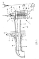
- the suction device consists of the suction pipe 16 and an injector attachment with an annular channel 23, which is connected via air supply 22 to a compressed air source. Blow ducts 21 lead from the ring duct 23 into the thread outlet duct 31, where the compressed air flowing out generates a strong suction flow in the direction of the arrow.
- the yarn feed mechanism 1 Before the inlet of the suction pipe 16, the yarn feed mechanism 1 is arranged transversely to the air duct axis 28.
- the bracket 40 is connected by connection 41 to the wall of the suction pipe 16.
- Two rollers 32, 33 are mounted in the holder 40 in such a way that that the roller axes 45, 46 extend at an acute angle 34 to one another.
- the delivery mechanism 1 It is particularly advantageous for the delivery mechanism 1 to be arranged in front of the intake pipe 16 in such a way that the air duct axis 48 extends essentially in a plane tangent to the two rollers 32, 33.
- the air duct axis 48 strikes the yarn feed mechanism 1 in its end or outlet area 47, while a substantial part of the longitudinal extent of the feed mechanism 1 projects laterally beyond the suction pipe 16. It is therefore provided that the thread runs in the area of the smaller center distance from the delivery mechanism 1.
- the thread outlet 31 is connected to a flexible tube which leads into a waste container.
- the thread take-off device forms a handling unit which has a handle, not shown.
- the suction pipe 16 and / or the thread outlet channel 31 can serve as a handle.
- the roller 32 is driven by a high-speed electric motor in the drive housing 8.
- the drive housing 8 is fastened on the holder 40.
- the roller 33 is freely rotatable in the holder 40.
- the thread coming, for example, from the spinneret 57 is first drawn straight into the suction tube 16 of the suction device 24 in operation: thread run 20.1, shown in broken lines. It should be taken into account that the thread is not delivered by the spinneret 57 at a defined speed. Therefore, the suction forces exerted by the suction device 24 are sufficient to pull off the thread and to prevent it from becoming entangled and knotted.
- the roller 32 has also been set in rotation, the rotational speed of the roller being so high that its peripheral speed essentially corresponds to the nominal speed of the thread and the peripheral speed of the feed mechanism 30, to which that of the spinneret coming thread to be created corresponds.
- the thread pulling device is pivoted several times so that the supply unit 1 executes a wobbling movement around the thread axis, so that the thread which has just been running is looped once or several times around the two rollers 32, 33 of the supply unit
- the delivery mechanism and in particular the driven roller 32 exerts an increasing frictional force on the thread, so that the thread is now drawn off with essentially its desired speed and high tensile force.
- the thread take-off device is now guided several times around the godet 30 and the thread is thereby placed on the godet 30 with the desired number of wraps (thread path 20.2).
- the thread can now be placed with the thread take-off device on a winding device 49, which is only indicated schematically (thread run 20.3).
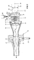
- the delivery unit 1 and the suction device 24 are essentially coaxial or parallel, the outlet end 47 of the delivery unit 1 pointing to the inlet of the expanded suction channel 16. It is shown that the outlet end 47 of the delivery unit 1 projects into the enlarged inlet of the suction channel 16.
- the suction channel 16 opens parallel over the plane in which the two roller axes 45, 46 lie.
- the holder 40 in which the rollers 32, 33 are mounted, is connected to the wall of the suction pipe 16 by connection 41.
- the two roller axes 45, 46 of the delivery mechanism 1 run at an acute angle to one another.
- a cap 43 with counter bearing supports the two rollers on its free end and covers the run-up ends of the two rollers so that its edge largely prevents the thread from slipping off the rollers 32, 33.
- the suction pipe 16 is in turn connected to a suction device 24, which consists of an annular duct 23 with a compressed air connection 22 and the blowing ducts 21 and generate a strong suction flow in the suction pipe 16.
- the thread is discharged into the waste through thread outlet channel 31.
- the thread coming from the spinneret is first caught in the suction tube 16 by the suction device 24 and drawn off straight in the thread path 20.1.
- the thread take-off device is pivoted several times in such a way that the air duct axis 48 and the delivery mechanism execute a wobbling movement around this thread run 20.1, so that a desired number of turns are formed on the delivery mechanism 1.
- the rollers 32 and 33 of the delivery mechanism were put into operation by an air turbine located in the holder 40. Therefore, the thread is now withdrawn from the spinneret at the speed and tensile force specified by the air turbine.
- the connection 41 serves at the same time as a thread guide, which prevents the thread from being pulled off the delivery mechanism by the delivery mechanism due to the suction force exerted by the suction device.
- the thread 20 to be drawn is in each case wrapped in a plurality of turns 36 around the two rollers 32, 33 of the thread feed unit 1 in operation and is drawn off with increased tensile force as a result of the frictional contact between the rollers 32, 33 and the thread which results.
- the arrangement of the two rollers 32, 33 at an angle 34 causes each other that the individual thread turns 36 are axially offset from each other. In the area of the outlet end 47 of the thread feeder 1, the thread is taken over and removed by the suction flow of the suction tube 16.
- the two rollers 32, 33 with their axes 45, 46 form an acute angle 34 to one another.
- the arrangement can also be such that the axes 45 and 46 lie in two substantially parallel planes and thus to one another aligned that they intersect in the projection in one of the two planes at an acute angle.
- At least one of the two rollers 32, 33 is driven at such a high speed that the peripheral speed corresponds at least to the thread speed.
- This can e.g. in that an air turbine is arranged in the holder 40, as described, but the drive by an electric motor is also possible.
- a thread can be applied to godets and other thread conveyors, in particular also to a winding device, at peripheral speeds which are well over 4,000 e.g. 7,000 m / min. This is obviously due to the fact that the necessary thread tension is generated by the thread feed mechanism 1 and can be set so high that no winder forms on the godet or the winding device. High flow velocities are then required to remove the thread running from the feed mechanism 1, but only relatively low tensile forces are required.
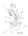
- FIGS. 3A, 3B, 3C serve to explain a thread take-off device with an application device for the thread.
- the rollers 32 and 33 of the thread feed mechanism 1 are rotatably mounted on the holder 40.
- Roller 33 is driven by a turbine, whose housing is designated 8, driven.
- the roller axes of rollers 32 and 33 intersect at an acute angle.
- Heath rollers are mounted in the holder 40 in such a way that their center distance decreases from their free end to their bearing end 47.
- the drive direction of the roller 33 is indicated by arrow 35.
- the suction device lying in the holding device 40, the suction tube 16 of which lies between the two rollers 32 and 33 and above the plane connecting the roller axes, is accommodated in the holder 40.
- the suction device consists, as has already been described for the embodiment of FIGS. 1 and 2, of an annular channel, which surrounds the suction channel 16 and is connected to it by blowing channels.
- the ring channel is supplied with compressed air through a compressed air connection 22.
- the compressed air connection 22 penetrates a handle 39 at the same time.
- the channel guide inside the holder 40 is not shown in detail.
- the thread application device is a U-shaped bracket 50.
- the bracket 50 is pivotally mounted at one end in the holder 40. The end is arranged essentially parallel to the bisector between the two roller axes. Furthermore, the pivot bearing in the holder 40 and the bearing end of the bracket 50 has a high helix thread 51, the function of which will be described later.
- a thread guide 52 is mounted on the other U flank. This thread guide 52 is a so-called "wolf tooth", i.e. the thread guide 52 has a catch slot into which the thread can enter laterally but not out again.
- the thread guide 52 is pivotable about axis 53, but the thread guide is not axially movable.
- the bracket 50 can be pivoted in the direction of the arrow 54, ie in the direction of rotation of the yarn feed mechanism.
- the suction device ends in a thread outlet channel 31 to which a waste bag 44 is clamped.
- the steep thread 51 is designed so that when the bracket 50 is pivoted in the direction of arrow 54, the bracket executes an axial movement in the direction of arrow 55.
- the thread pulling device is handled as follows for thread catching and for threading the thread on a godet; First, the thread coming from a spinneret, not shown, is brought into the area of the mouth of the suction tube 16 and drawn off. This is possible because the thread is not delivered by the spinneret at a defined and particularly high speed. In the meantime, the air turbine in the housing 8 has also been pressurized with compressed air and consequently the roller 33 is set in rotation, so that the roller is driven essentially at the desired peripheral speed of the godet 30 (FIG. 3C) to which the thread is to be applied. The thread has a thread run 20.1 (Fig. 3A). The bracket 50 is now rotated against the direction of the arrow 54.
- the thread guide 52 gets into the thread path and catches the thread with its "wolf tooth” (FIG. 3A).
- the bracket 50 is now rotated in the direction of the arrow 54. 3B shows, the thread guide 52 can adjust itself to the thread by pivoting about axis 53.
- the pivoting movement of the bracket 50 in the direction of arrow 54 winds the thread around the rollers 33 and 32. Since, during the rotational movement in the direction 54, the bracket 50 simultaneously executes an axial movement in the direction of the arrow 55 as a result of the pitch of the steep thread 51, as shown in FIG. 3C, several axially offset thread turns 36 are wound around the rollers 32, 33.
- the now maintained thread path 20.3 is characterized in that the incoming thread is first passed through the thread guide 52, redirected by this thread guide 52 to the roller 33, then guided in two essentially complete loops around the rollers 32 and 33 and then in the area of the End 47 of the roller is sucked off the roller 33 in the suction opening 16 and guided into the waste bag 44.
- the thread can now be placed against the godet 30 rotating at high peripheral speed (FIG. 3C) and possibly also a subsequent winding device.
- the suction pipe 16 of the suction device not shown in the rest, opens in the region of the outlet end 47 of the roller 33, the roller 33 is driven with the direction of rotation 35.
- An air turbine can be used for the drive, which, like the suction device, is fed with compressed air through compressed air connection 22.
- the suction device is constructed, for example, as described in connection with the exemplary embodiments according to FIGS. 1 to 3.
- the application device in turn consists of a U-shaped bracket 50.
- One U flank is coaxially mounted in a pivotable direction 54, but independently of the roller 33.
- the other free U flank has a thread-shaped thread guide 56 at its end.
- the thread is first caught by the mouth of the suction device 16 and drawn off with a thread run 20.1 (dashed line).
- the bracket is pivoted into position 50.1, in which the threaded wire 56 engages behind the thread in the thread path 20.1 with its outermost end.
- the bracket 50 is now rotated further with the pivoting direction 54.
- the pitch of the threaded wire 56 is selected so that the thread rises in the threads with the direction of arrow 55.
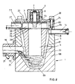
- FIGS. 5 to 7 The embodiment of FIGS. 5 to 7 is characterized by pneumatic means for threading.
- the conical roller 33 of the yarn feeder 1 is firmly connected to the shaft 2 and the turbine wheel 3.
- the shaft 2 is rotatably supported between the conical roller 33 and the turbine wheel 3 by bearings 4 in the housing 5.
- the housing 5 consists of a trigger housing 6, a bearing housing 7 and a drive housing 8.
- a conical bore 9 is made in the trigger housing 6 and ends in a cylindrical bore 10.
- the conical bore surrounds the conical roller 33 with a narrow gap 11.
- the gap 11 is e.g. 1 mm wide.
- a groove 12 is cut, which is helical.
- the inlet end 13 of the groove 12 is aligned with the thread inlet channel 14.
- the outlet end 15 of the groove 12 is aligned with the thread suction channel 16.
- the thread inlet channel 14 can be filled with injector nozzles 17, which are fed via the air connection 18 and the ring channel 19.
- the injector 17, 18, 19 generates a negative pressure in the entrance of the thread inlet channel 14, so that a supplied thread end 20 is sucked in here.
- a suction device 24 is arranged behind the roller 1.
- the thread suction channel 16 is filled with the injector nozzles 21, which also point in the thread running direction and which are fed through the air inlet tube 22 and the ring channel 23.
- the injector 21, 22, 23 generates or supports the suction air flow in the channel strip, which consists of thread inlet channel 14, groove 12 and thread suction channel 16.
- the turbine wheel 3 is fixedly attached to the shaft end 2, which faces away from the conical roller 1.
- the turbine wheel 3 consists of the two end disks 25, between which the turbine blades 26 (section according to FIG. 7) are fastened, e.g. by welding.
- One end disk 25 of the turbine wheel 3 is firmly seated on the shaft 2.
- the turbine housing 8 forms an annular channel 80 with and around the turbine wheel 3.
- the compressed air channel 27 opens into this annular channel.
- the compressed air channel 27 is directed essentially tangentially into the annular channel. Its orientation and the shape of its mouth is generally known in the construction of compressed air turbines and is not described in more detail here.
- the required air pressure can build up in the ring channel 80.
- the turbine wheel can be driven at speeds of up to 10,000 rpm.
- the blades 26 of the turbine wheel 3 leave the outflow channel 28 free in the center of the turbine wheel.
- the outflow channel is closed on the bearing side by an end plate 25.
- the outflow channel 18 opens to the free end of the shaft 2 in the axial air outlet 29 of the housing, the end plate 25 also having a correspondingly large hole.
- the groove 12 in the jacket of the conical bore 9 is particularly advantageous for threading, in particular for safety in catching and the reproducibility of thread catching is.
- the groove creates a flow field of high energy in the cross-sectional area of the groove, the flow direction of which is well defined by the groove geometry. This ensures that the thread is conveyed from the thread inlet channel 14 and the inlet end 13 of the groove to the outlet end 15 of the groove and thus into the thread suction channel 16.
- the compressed air channel 27 is pressurized with compressed air and the turbine wheel 3 with the shaft 2 and the winding body 1 is thereby rotated until the peripheral speed of the godet 30 is reached.
- the injector nozzles 17 and 21 are charged with compressed air via air connection lines 18 and in particular 22. This creates a suction flow at the entrance of the thread inlet channel 14, which continues as a vortex flow around the roller 1 and as an air flow in the outlet channel 16.
- the air speed is higher than the thread speed.
- the thread is wound in a swirl of air around the cone roller 1 in a fraction of a second. It is inevitable that the thread comes into contact with the cone roller. Now the thread is drawn off by frictional contact with the conical roller 1.
- the peripheral speed of the conical roller 1 in the area of the thread inlet plane is at least equal to the thread speed specified by the feed mechanism 30.
- the peripheral speed of the conical roller 1 is also greater in the area of the thread outlet (groove end 15) than the thread speed. Therefore, the cone exerts considerable friction on the thread. This frictional force is sufficient to pull the thread with such high thread tension subtract from the lowering unit 30 in such a way that it can be applied to the supply unit 30 without a thread winder forming on the supply unit 30.
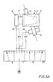
- 5A shows a manual sequence control.
- the air supply is switched off without operation (position I).
- position II of the valve set by hand only the air turbine is supplied with compressed air via line 27.
- the valve is then switched to a further operating position III.
- position III the suction device 24 is acted upon via line 22 with the essential part of the available compressed air quantity, while the turbine now receives a reduced quantity via a throttle. It is also possible to completely shut off the supply line to the turbine via the throttle.
- the valve is switched so that the suction device 24 is only supplied with compressed air via another throttle, while the essential part of the compressed air is supplied to the turbine.
- the rotation of the roller 1 contributes in particular to the formation of eddies and the thread transport with axial feed from the thread inlet to the thread outlet.
- the thread inlet can lie on the same normal plane as the thread outlet.
- the risk of winder formation is somewhat coarser.
- Fin axial feed is achieved in particular by _ thread inlet channel, as is also shown in FIG. 5 and thread suction channel are axially offset from one another and that the suction device lies behind the roller, that is to say in the thread suction channel, so that a defined suction flow results from the thread inlet into the thread outlet. This reduces the risk of winders.
- the air flow in the channel strip consisting of thread inlet duct 14, groove 12 and thread suction duct 16 can be substantially reduced, since the thread conveyance now takes place essentially by frictional contact with the conical roller 1.
- the cone roller has a continuously decreasing diameter towards its free end in the entire area that comes into contact with the thread.
- the coefficient of friction and the cone angle are coordinated so that the thread cannot be held on the surface by self-locking, but in any case slips when it is under the corresponding thread tension. For this reason, it is excluded that a winder forms on the cone roller 1. Fin winder will automatically tend to slip towards the free end of the roller. The winder must also pass the groove end 15 or the entrance of the thread suction channel 16. Most winders are therefore already caught here and suctioned through the thread suction channel 16 by means of the injectors 21.
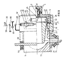
- FIGS. 8 and 9. 8 is constructed as follows:
- the housing 5 has a bore which is conical in its lower part 9.
- the housing 5 is closed on its upper face by a cover 77.
- the cover 77 is connected to the housing by screws 74.
- a socket 8 of the cover 77 which is concentric with the pipe 9 in the housing 5, there is the position 4 of the winding body 1.
- the winding body 1 is part of a structural unit with the shaft 2, the turbine wheel 3 and the winding body 1.
- the shaft 2 is firmly connected to an end face 25 of the turbine wheel and is freely rotatably supported in the bushing 8 by two ball bearings.
- the turbine wheel 3 consists of the two end disks 25, between which the turbine blades 26 (section according to FIG. 7) are fastened, for example by welding.
- the winding body 1 is seated on one end disk 25 of the turbine wheel 3.
- the winding body 1 is a bonus which has essentially the same conicity as the bore 9 in the housing 5.
- the winding body forms an annular thread chamber 9 in this bore, which also tapers conically towards the free end of the winding body 1 with respect to its mean diameter.
- the cone angle of the winding body 1 is smaller than the cone angle of the bore 9.
- the width of the thread chamber 9 also tapers towards the end of the winding body 1.
- the winding body 1 has a bead 38 which forms a narrow channel in the form of an annular nozzle 79 with the cylindrical part of the bore in the housing 5.
- the upper cylindrical part of the bore in the housing 5 forms an annular channel 80 with and around the turbine wheel 3.
- the compressed air channel 27 opens into this annular channel 80.
- the compressed air channel 27 is directed essentially tangentially into the annular channel. Its orientation and the shape of its mouth is generally known in the construction of compressed air turbines and is not described in more detail here. Since the bead 38 of the winding body 1 of the cylindrical chamber wall in the housing 5 forms an annular nozzle with strong throttle resistance, the required air pressure can build up in the annular channel 80.
- the turbine wheel can be driven at speeds of up to 10,000 rpm.
- the blades 26 of the turbine wheel leave the outflow channel 28 free in the center of the turbine wheel.
- the outflow channel is closed on the bearing side by the end plate 25.
- the outflow channel 28 opens to the free end of the winding body 1 in its central channel 81, the other end plate 25 also having a correspondingly large hole.
- the pin 73 in the center of the turbine wheel 3 is shaped such that the air passing between the blades 26 is deflected in the direction of the central channel 81 in the winding body 1.
- the thread inlet 14 opens into the housing bore 5.
- the thread inlet 14 lies essentially on a tangential plane of the winding body 1.
- the thread inlet 14 can lie on a normal plane of the winding body 1.
- the thread inlet channel 14 can also be arranged such that it crosses the axis of the winding body 1 at an obtuse angle in the projection according to FIG. 8.
- the thread conveyed by thread inlet 14 can also have a movement component in the direction of the free end of the winding body 1.
- An end piece 68 is attached to the housing 5.
- the thread chamber 9 ends in a conical, rounded blind hole 69.
- the end piece 68 also has a wide incision 70 on its edge.
- the incision is rounded towards the blind hole and, in the installed state, lies in a normal plane in the region of the thinnest end of the rotating body 1.
- the incision 70 is aligned with the suction channel 16, which is flanged to the housing end piece 68 and is fitted with injectors 21.
- the cross section of the suction channel 16 is essentially adapted to the adjacent cross section of the incision 70 with which the incision 70 opens into the suction channel 16.
- the windings collect and as a result of the air flow coming through the central channel 81 _ starting from the turbine wheel 3 _ and as a result of the air flow in the filament chamber 9, the vault falling from the rotating body 1 is not only collected in the blind hole 69, but also due to the air flow to the suction channel 16 at the same time also promoted in the direction of the incision 70 and the suction channel 16.
- the bulge is detected by the injectors 21 and placed under a certain tension. This causes the vault to pull out into a smooth thread again. Since the suction channel 16 lies in a normal plane which intersects the rotary body in the region of its thinnest, the thread is now drawn off tangentially from the rotary body, as indicated by line 71.
- the suction device receives only so much compressed air that a sufficiently high thread tension 52 of the thread running off the roller 1 is generated in order to generate the thread tension resulting from the looping in the thread running towards the roller 1.
- the thread turns which are formed in the normal plane of the thread inlet in the rotating body, continue to slide due to the conicity, the low friction and the air flow on the cone.
- the thread tension in the reverberation of the thread inlet 14 can be adjusted by setting the speed and the torque of the rotating body 1 as desired and so high that a godet (not shown here) can be applied without the winder being formed on the godet.
- the turns slipping on the bonus lose their thread tension, so that the thread can be easily conveyed in the suction channel 16.
- the suction flow required for this can be generated with the injectors 21 without any particular effort.
- the thread pulling device is also suitable for storing a thread in the form of a fleece, felt or as waste.
- FIG. 9 essentially corresponds to the embodiment according to FIG. 8 with regard to the thread guidance.
- This thread take-off device can be used in particular for waste disposal or for the further processing of the thread.
- the housing 5 has a wide slot 61 on its circumference. This slot extends over part of the circumference with such a central angle that the thread can be placed through this slot 61 with a wrap around the winding body 1.
- a casing 62 is displaceable on the housing 5. The jacket is pressed into its outer right position by spring 63. The force of the springs can be adjusted by screw 64.
- the jacket 62 has the thread inlet connector 14 on its circumference.
- the thread inlet nozzle is directed essentially tangentially to the circumference of the rotating body 1 and its thread channel also extends through the jacket 62.
- the thread inlet nozzle 14 can be populated with the indicated injectors 18 which cause a suction flow in the inlet nozzle.
- the thread inlet connector 14 is designed so that it lies in the outer right position, which is shown in Fig. 9, substantially on the normal plane and the working area of the winding body, which has the largest diameter.
- the thread guide 65 is fastened to the jacket 62.
- the thread 59 coming from a spinneret and to be applied to the take-off unit 60 or coming from the take-off unit 60 is tensioned between the fixed thread guides 66 and 67 on the one hand and the thread guide 65 movable with the jacket 62 on the other hand.
- the jacket 62 is shifted to the left against the force of the spring 63 as the thread tension increases.
- Fixed means that the thread guides are immovable with respect to the housing 5 of the thread take-off device.
- Threading in circumferential contact with the rotating body is facilitated if the jacket 62 is moved to the left against the spring force 63 in FIG. 9, so that the thread initially runs onto a smaller diameter of the rotating body 1. After catching, the jacket is released into its right extreme position predetermined by the spring 63 and a stop.
- the thread turns on the rotating body continue to slide due to the taper and the low friction, the thread tension above the thread inlet 14 not only by adjusting the speed of the rotating body 1, but also by shifting the jacket 62 and thus the point of the thread on the roller 1 as desired and can be set so high that the thread can be placed on the delivery godet 30 running at a constant, high peripheral speed without 30 winder being produced on the delivery godet.
- the turns slipping on the cone lose their thread tension, so that the thread, e.g. is guided into the waste or onto a collection or transport container in which the suction channel 16 can easily be conveyed.
- the air flow required for this can be generated with the injectors 21 without any particular effort.
- the thread can also be withdrawn from another delivery plant.
- the thread pulling device can regulate the thread tension between the Delivery godet 30 and the thread take-off device are used.
- the thread is placed around the thread guides 66, 67, 65 in the manner shown, which serve to measure the thread tension.
- the width of the slot 61 determines the working area in which the point of the thread can be moved onto the winding body 1.
- the thread is wound on the winding body 1 at a higher or lower winding speed.
- the thread tension can be controlled and regulated by adjusting the position of the jacket 62.
- the thread guide 65 and thus also the jacket 62 are shifted to the left.
- the thread inlet connector 14 lies on a normal plane with a smaller diameter.
- the winding speed drops and the thread tension decreases. There is therefore an equilibrium state between the thread tension on the one hand and the spring force 63.
- the target value of the thread tension can be specified by setting the spring force 63. This ensures that the thread tension, which is given to the thread by the take-off device, is always sufficient to avoid winders on the take-off mechanism 60 or to exert constant thread forces on the thread to influence the thread properties.
Description
Die Erfindung betrifft ein Fadenabzuggerät zum Abziehen eines kontinuierlich laufenden Fadens mit einer den Faden in einem Luftstrom abführenden Saugvorrichtung. Außerdem betrifft die Erfindung Verfahren zum Anlegen eines frischgesponnenen, von der Spinndüse kommenden Chemiefadens an schnell drehende Maschinenteile.The invention relates to a thread take-off device for pulling a continuously running thread with a suction device which removes the thread in an air stream. In addition, the invention relates to methods for applying a freshly spun chemical thread coming from the spinneret to rapidly rotating machine parts.
Die Erfindung löst die Aufgabe, die sog. Saugpistolen bzw. sonstigen Saugvorrichtungen so auszugestalten, daß sie auch bei hohen Fadengeschwindigkeiten von mehr als 4.000 m/min ausreichend hohe Fadenzugkräfte aufbringen können.The invention solves the problem of designing the so-called suction guns or other suction devices in such a way that they can apply sufficiently high thread tensile forces even at high thread speeds of more than 4,000 m / min.
Saugpistolen bzw. sonstige Saugvorrichtungen dienen dem Zweck, kontinuierlich anfallende Fäden, insbesondere Chemiefasern während der Betriebsunterbrechung, z.B. während des Spulenwechsels in einer Chemiefaser-Spinnmaschine, abzuziehen und dem Abfall zuzuführen. In diesen Saugpistolen wird der Faden einer starken Luftströmung unterworfen. Die Grenze der Einsatzmöglichkeit solcher Geräte liegt jedoch bei Fadengeschwindigkeiten von ca. 4000 m/min (65 bis 70 m/s). Dabei wird es insbesondere unmöglich, die erforderlichen Fadenspannungen aufzubringen, wenn der Faden an Galetten oder Aufwickelmaschinen angelegt werden soll und/oder mittels Galetten gefördert wird. Es besteht hierbei die Gefahr, daß der Faden infolge zu geringer Fadenspannung einen Wickler auf der Galette/Aufwickelmaschine bildet. Bei diesen Fadengeschwindigkeiten stellen zudem die wegen des sehr hohen Leistungsbedarfs erforderlichen Kompressoren oder Vakuumpumpen einen bedeutenden Kostenfaktor dar, obwohl diese Maschinen jeweils nur kurzfristig bei Betriebsunterbrechungen benötigt werden.Suction guns or other suction devices serve the purpose of pulling off continuously occurring threads, in particular man-made fibers during the business interruption, for example during the bobbin change in a man-made fiber spinning machine, and feeding them to the waste. The thread is subjected to a strong air flow in these suction pistols. However, the limit of the possibility of using such devices is at thread speeds of approx. 4000 m / min (65 to 70 m / s). It becomes particularly impossible to apply the necessary thread tensions when the thread is to be placed on godets or winding machines and / or is conveyed by means of godets. There is a risk that the thread will form a winder on the godet / winding machine due to insufficient thread tension. At these thread speeds, the compressors or are required because of the very high power requirement Vacuum pumps represent a significant cost factor, although these machines are only needed for short periods in the event of business interruptions.
Schließlich ist der Wirkungsgrad derartiger Saugpistolen und Luftinjektoren derart gering, daß bei hohen Fadengeschwindigkeiten ein wirtschaftlicher Einsatz nicht mehr gegeben ist.Finally, the efficiency of such suction pistols and air injectors is so low that economical use is no longer possible at high thread speeds.
Um die Grenze von ca. 4000 m/min durch Fadenabsauggeräte überschreiten und ausreichende Fadenzugkräfte erzeugen zu können, wurde vorgeschlagen, die Saugströmung durch eine Flüssigkeit, insbesondere durch Wasser, zu erzeugen, wobei Drücke von ca. 80 bar und mehr genannt wurden. Dieses Verfahren führte jedoch nicht zum Erfolg. Einmal stellte die Notwendigkeit, die anfallenden Wassermengen jeweils ohne übermäßigen Aufwand zu beseitigen, eine kaum zu bewältigende Aufgabe dar. Außerdem ergaben sich strömungstechnische Hindernisse, da selbst für das freie Ausströmen einer reibungsfreien Flüssigkeit ein Druck von 51 bar erforderlich ist, um eine Strömungsgeschwindigkeit von 6000 m/min (100 m/s) zu erhalten. Schließlich muß der Faden zunächst von einer Luft-Saugströmung und dann von dem Flüssigkeitsstrom übernommen werden, was nur unvollständig gelingt.In order to be able to exceed the limit of approx. 4000 m / min with thread suction devices and to be able to generate sufficient thread tensile forces, it was proposed to generate the suction flow through a liquid, in particular through water, wherein pressures of approx. 80 bar and more were mentioned. However, this procedure was unsuccessful. On the one hand, the need to remove the water quantities without excessive effort was a difficult task. In addition, there were flow-related obstacles, since even for the free flow of a friction-free liquid, a pressure of 51 bar is required to achieve a flow rate of 6000 m / min (100 m / s). Finally, the thread must first be taken over by an air suction flow and then by the liquid flow, which is only incomplete.
Nach der Erfindung wird der Saugvorricntung ein Fadenlieferwerk unmittelbar vorgeordnet. Dieses Fadenlieferwerk besteht aus zumindest einer angetriebenen, vom Faden zu umschlingenden Rolle. Die Saugmündung wird in unmittelbarer Nachbarschaft zur Oberfläche der Rolle im Fadenlauf hinter der Rolle und vorzugsweise auf einer Auslauftangente derselben angeordnet.According to the invention, the threading device is arranged directly upstream of the suction device. This thread feed mechanism consists of at least one driven roller to be looped by the thread. The suction mouth is arranged in the immediate vicinity of the surface of the roll in the thread path behind the roll and preferably on an outlet tangent thereof.
Die Erfindung sieht weiterhin Maßnahmen vor, durch die gewährleistet wird, daß der Faden auf dem Fadenlieferwerk keine Wickler bildet. In einer Ausgestaltung werden hierzu zwei mit geringem Abstand nebeneinander angeordnete, gleichsinnig umlaufende Rollen vorgesehen, von denen wenigstens eine antreibbar ist und deren Rollenachsen gegeneinander verschränkt sind oder miteinander einen spitzen Winkel bilden. Der Faden wird so über dieses Lieferwerk geführt, daß er im Bereich des weiten Achsabstandes auf die Rollen aufläuft und daß die Saugvorrichtung im Bereich geringen Rollenabstands angeordnet ist. Bei dieser Ausführung kann sich die Saugvorrichtung im wesentlichen in axialer Richtung an das Tieferwerk anschließen oder das Ende des Lieferwerks umgreifen, wobei ein Fadenführer vorhanden sein muß, der verhindert, daß der Faden sich von dem Lieferwerk über Kopf wieder abwickelt. Alternativ kann die Saugvorrichtung quer zu den Rollenachsen angeordnet sein, so daß der Faden tangential von den Rollen abgezogen wird.The invention further provides measures by which it is ensured that the thread does not form any winders on the thread feed mechanism. In one embodiment, this two rollers arranged at a short distance from one another and rotating in the same direction are provided, at least one of which can be driven and the roller axes of which are interleaved or form an acute angle with one another. The thread is guided over this feed mechanism in such a way that it runs onto the rollers in the area of the wide center distance and that the suction device is arranged in the area of the small roller distance. In this embodiment, the suction device can connect to the lower works substantially in the axial direction or encompass the end of the supply works, whereby a thread guide must be present which prevents the thread from unwinding again overhead from the supply works. Alternatively, the suction device can be arranged transversely to the roll axes, so that the thread is drawn off tangentially from the rolls.
Alternativ wird die Wicklerbildung dadurch vermieden, daß das Fadenlieferwerk aus nur einer Rolle, die konisch ausgeführt ist, gebildet wird. In dieser Ausführung wird die Rolle an ihrem dicken Ende fliegend gelagert, so daß eventuell sich bildende Wickler stets zum dünnen Ende hin abrutschen und, dort beseitigt werden können. Andererseits wird durch die Konizität ein ständiger, axialer Vorschub bewirkt, so daß sich _ ebenso wie bei dem Lieferwerk mit zwei Rollen, deren Achsen zueinander verschränkt sind _ nicht mehrere Windungen übereinander legen.Alternatively, the formation of the winder is avoided in that the thread feed mechanism is formed from only one roll, which is of conical design. In this embodiment, the roll is cantilevered at its thick end, so that any curlers that may form always slide off towards the thin end and can be removed there. On the other hand, due to the taper, a constant, axial feed is effected, so that _ as with the delivery unit with two rollers, the axes of which are interlaced with one another, _ several turns are not superimposed.
Das Fadenabzuggerät nach dieser Erfindung kann als ortsfeste Einheit montiert sein, wobei in diesem Falle gleichzeitig mechanische oder pneumatische Mittel zum Anlegen des Fadens an das Fadenlieferwerk vorgesehen sein müssen. Vor allem aber kann das Fadenabzuggerät als tragbares Handhabungsgerät, vergleichbar den bisherigen Saugpistolen ausgestaltet sein.The thread take-off device according to this invention can be mounted as a stationary unit, in which case mechanical or pneumatic means for applying the thread to the thread feed mechanism must be provided at the same time. Above all, however, the thread take-off device can be designed as a portable handling device, comparable to the previous suction pistols.
Nach der Erfindung stehen zum Anlegen des Fadens an das Fadenlieferwerk des Fadenabzuggeräts mehrere Vorrichtungen und darauf zugeschnittene Vorgehensweisen zur Verfügung.According to the invention, several devices and procedures tailored to them are available for applying the thread to the thread feed mechanism of the thread take-off device.
Wenn die Rolle bzw. die Rollen des Fadenlieferwerks fliegend gelagert werden und die Saugvorrichtung am Bereich des Lagerendes angeordnet wird, wird das folgende Verfahren insbesondere in Chemiefaser-Spinnanlagen vorgeschlagen: Der von der Spinndüse mit verhältnismäßig geringer Geschwindigkeit anfallende Faden wird zunächst von der Saugvorrichtung eingefangen, so daß der Faden mit der von der Saugvorrichtung allein erzeugbaren Zugkraft abgezogen wird. Nunmehr wird das Handhabungsgerät derart verschwenkt, daß die Rollenachse bzw. Rollenachsen den Fadenlauf in einer taumelnden Bewegung einmal oder mehrere Male umfahren. Dadurch bildet der Faden eine oder mehrere Umschlingungen auf der Rolle bzw. den Rollen. Dabei muß das Handhabungsgerät am Ende dieses Vorganges so gehalten werden, oder der Faden muß am Ende dieses Vorganges in einem an dem Handhabungsgerät befindlichen Fadenführer so eingelegt. werden, daß er den Rollen bzw. der Rolle im wesentlichen tangential zuläuft. Auf diese Weise wird vermieden, daß der Auflaufpunkt des Fadens auf das Lieferwerk in axialer Richtung wandert. Nunmehr kann durch das Fadenabzuggerät eine so hohe Fadenspannung auf den Faden ausgeübt werden, daß der Faden ohne die Gefahr der Wicklerbildung an hochtourige Maschinenteile wie Galetten und/oder Aufwickeleinrichtungen angelegt werden kann.If the roll or rolls of the yarn feeder are stored on the fly and the suction device is arranged at the area of the bearing end, the following method is proposed, in particular in chemical fiber spinning systems: the thread which is produced by the spinneret at a relatively low speed is first caught by the suction device, so that the thread is drawn off with the tensile force that can be generated by the suction device alone. Now the handling device is pivoted in such a way that the roller axis or roller axes traverse the thread path once or several times in a wobbling movement. As a result, the thread forms one or more loops on the roll or rolls. The handling device must be held in this way at the end of this process, or the thread must be inserted in a thread guide located on the handling device at the end of this process. be that it tapers to the roles or the role substantially tangentially. In this way it is avoided that the point of run-up of the thread migrates to the feed mechanism in the axial direction. The thread pulling device can now exert such a high thread tension on the thread that the thread can be applied to high-speed machine parts such as godets and / or winding devices without the risk of winder formation.
Auch mechanische Möglichkeiten zum Anlegen des Fadens stehen zur Verfügung. Auch hierbei ist die Vorgehensweise so, daß zunächst der Faden von der Saugvorrichtung eingefangen wird. Dann wird die mechanische Anlegvorrichtung in Betrieb gesetzt. Auch dieses Verfahren eignet sich also vor allem in Spinnanlagen zum Einfangen des von der Düse kommenden Fadens. Nach dem Anlegen des Fadens an das Lieferwerk des Fadenabzuggeräts kann der Faden mit hoher Fadenspannung auch an hochtourige Maschinenteile wie Galetten und/oder Aufwickeleinrichtungen angelegt werden.Mechanical options for threading are also available. Here too, the procedure is such that the thread is first caught by the suction device. Then the mechanical application device is put into operation. This method is also particularly suitable in spinning systems for catching the thread coming from the nozzle. After threading the thread to the Thread take-off device, the thread with high thread tension can also be applied to high-speed machine parts such as godets and / or winding devices.
Wenn der Faden an das Fadenlieferwerk angelegt ist, wird er mit größerer Zugkraft abgezogen, wobei die Zugkraft zum einen dem Drehmoment des Antriebsmotors und zum anderen der Zahl der Umschlingungen entspricht. Die Drehmomentcharakteristik des Motors einerseits und die Anzahl der Umschlingungen müssen so aufeinander abgestimmt sein, daß es nicht zum Fadenbruch kommt. Die Saugvorrichtung dient nunmehr lediglich noch zu dem Zweck, eine geringe Zugkraft im ablaufenden Fadenende aufzubringen. Diese Zugkraft im ablaufenden Fadenende muß lediglich so groß sein, daß eine ausreichende Zugkraft im zulaufenden Fadenende durch Umschlingungsreibung induziert wird. Andererseits kann auch eine nur geringe Zuggraft des ablaufenden Fadenendes kompensiert werden durch zusätzliche Umschlingung.
Eine zusätzliche Möglichkeit zur Einstellung und/oder Regelung der Fadenspannung wird dadurch gegeben, daß der Auflaufpunkt des Fadens axial einstellbar ist und daß das Fadenlieferwerk aus einer konischen Rolle besteht.When the thread is applied to the thread feed mechanism, it is drawn off with greater tensile force, the tensile force corresponding on the one hand to the torque of the drive motor and on the other hand to the number of wraps. The torque characteristics of the motor on the one hand and the number of wraps must be coordinated so that there is no thread breakage. The suction device is now only used for the purpose of applying a low tensile force in the thread end running off. This tensile force in the running thread end only has to be so great that a sufficient tensile force in the incoming thread end is induced by wrap friction. On the other hand, only a low tensile force of the running thread end can be compensated for by additional looping.
An additional possibility for setting and / or regulating the thread tension is given in that the point at which the thread runs up is axially adjustable and in that the thread feed mechanism consists of a conical roller.
Mechanische Vorrichtungen zum Fadenanlegen können so ausgestaltet sein, daß das Fadenabzuggerät nach dem Einfangen des Fadens in der Saugvorrichtung um die Fadenachse verschwenkt wird.Mechanical devices for thread application can be designed such that the thread pulling device is pivoted about the thread axis after the thread has been caught in the suction device.
Durch die Erfindung wird jedoch eine mechanisch einfache und sicher wirkende Anlegeinrichtung vorgeschlagen. Die besteht aus einem Fadenführer, der das Fadenlieferwerk auf einer Einhüllenden umfährt und dabei den Fadenweg im Bereich der Saugvorrichtung durchfährt. Vorzugsweise erteilt der Fadenführer dabei dem Faden auch einen axialen Vorschub. Es kann sich dabei vor allem um einen Flyer-artigen Fadenführer handeln, der koaxial oder parallel zu der Rollenachse oder _ bei einem Fadenlieferwerk, das aus zwei Rollen besteht _ in einer Ebene zwischen den Rollenachsen schwenkbar gelagert ist. Der axiale Vorschub kann dadurch bewirkt werden, daß der Flyer in einem Gewinde gelagert ist oder daß der auf seinem Außenarm befindliche Fadenführer schraubenförmig ausgebildet ist.However, the invention proposes a mechanically simple and safe-acting application device. This consists of a thread guide that bypasses the thread feed mechanism on an envelope and thereby traverses the thread path in the area of the suction device. The thread guide preferably also gives the thread an axial feed. Above all, it can be a flyer-like thread guide that is coaxial or parallel to the roll axis or _ in a yarn feed unit that consists of two rollers _ is pivotally mounted in a plane between the roller axes. The axial feed can be effected in that the flyer is mounted in a thread or in that the thread guide located on its outer arm is of helical design.
Alternativ, stellt die Erfindung pneumatische Mittel zum Fadenanlegen bereit, die mit der Saugvorrichtung zusammenwirken. In einer Ausführung Wer Erfindung, die hohe Fadengeschwindigkeiten bei großer Fangsicherheit gestattet und die überdies in ihrer Handhabung sehr einfach und kleinbauend in ein Handhabungsgerät zu integrieren ist, wird-der den Faden fördernde Luftstrom tangential auf und in einem Wirbel um, eine Walze geführt und sodann tangential wieder abgezogen. Die Walze wird ständig mit der Drehrichtung des Wirbels angetrieben. Bei konisch ausgebildeter Walze trifft der Luftstrom auf den Walzenumfang in einer Normalebene im Bereich des dickeren Endes (Fadeneinlaufebene). In dieser Fadeneinlaufebene ist die Umfangsgeschwindigkeit mindestens gleich der Fadengeschwindigkeit. Der Luftwirbel setzt sich sodann in Richtung auf das dünnere Ende der konischen Walze fort.Alternatively, the invention provides pneumatic threading means which cooperate with the suction device. In one embodiment, whoever invention that allows high thread speeds with high catch safety and that is also very simple and compact to integrate into a handling device, the air flow conveying the thread is guided tangentially on and in a vortex, a roller and then subtracted tangentially. The roller is constantly driven with the direction of rotation of the vortex. With a conical roller, the air flow hits the roller circumference in a normal plane in the area of the thicker end (thread inlet plane). In this thread infeed plane, the peripheral speed is at least equal to the thread speed. The air vortex then continues towards the thinner end of the conical roller.
In einer wirksamen Ausführung ist die Walze zur Erzeugung des Luftwirbels von einem Strömungskanal umgeben, der mit der Walze einen engen Spalt bildet und zur Walze hin so weit offen ist, daß der Faden aus dem Strömungskanal heraus kann. Der Strömungskanal kann ein schraubenförmig gebogenes, geschlitztes Rohr sein. Für die Vermeidung von Wicklern ist es noch günstiger _ aus Gründen, die weiter unten erklärt werden _ wenn die Walze mit einem Gehäuse umgeben wird. Der Innenmantel dieses Gehäuses bildet mit der Walze einen engen Spalt. Die Spaltweite ist so bemessen, daß der Faden auf der Walze auch einen geringen Wickler bilden kann. In den Gehäuseinnenmantel ist als Strömungskanal eine schraubenförmige Nut eingeschnitten, die sich mit mindestens einer halben Windung um die Walze erstreckt. Fadeneinlaufkanal und Fadenauslaufkanal, die das Gehäuse durchdringen, münden jeweils vor bzw. hinter dieser Nut. Vorzugsweise fluchten die Kanäle mit den Nutenden. Die Walze kann zur Erzielung eines axialen Vorschubs der Fadenwindungen wiederum konisch ausgebildet sein. Der Gehäuseinnenraum kann ebenfalls konisch ausgebildet sein.In an effective embodiment, the roller for generating the air vortex is surrounded by a flow channel which forms a narrow gap with the roller and is so wide open to the roller that the thread can leave the flow channel. The flow channel can be a helically curved, slotted tube. For the avoidance of winders, it is even more favorable _ for reasons that are explained below _ if the roller is surrounded by a housing. The inner shell of this housing forms a narrow gap with the roller. The gap width is dimensioned so that the thread on the roller can also form a small winder. In the inner casing is a helical flow channel Cut groove that extends around the roller with at least half a turn. Thread inlet channel and thread outlet channel, which penetrate the housing, open in front of and behind this groove, respectively. The channels are preferably aligned with the groove ends. The roller can in turn be conical in order to achieve an axial advance of the thread turns. The interior of the housing can also be conical.
Konische Walzen haben überdies den Vorteil, daß sich an ihnen die Fadenzugkraft selbsttätig einstellt. Bei Überschreiten einer bestimmten Zugkraft rutschen die Fadenwindungen zum Bereich des dünnen Endes und damit in einen Bereich geringerer Umfangsgeschwindigkeit ab. Dieser Effekt kann _ wie beschrieben _ auch absichtlich durch Einstellung des Auflaufpunktes des Fadens erzielt werden.Conical rollers also have the advantage that the thread tension is automatically set on them. When a certain tensile force is exceeded, the thread turns slip to the area of the thin end and thus to an area of lower peripheral speed. As described, this effect can also be achieved deliberately by adjusting the thread's point of contact.
Eine andere Möglichkeit zur Erzeugung eines Luftwirbels besteht darin, daß die Walze in einem Gehäuse gelagert wird, das dem Walzenumfang mit Spalt angepaßt ist. in dieses Gehäuse münden der Fadenzulaufkanal und der Fadenabfuhrkanal, wobei beide Kanäle jeweils auf einer Tangente zur Walze liegen. Im übrigen ist die Innenwand des Gehäuses glatt. Die Drehrichtung wird dabei so gewählt, daß der Walzenumfang und die Luft gleichgerichtet sind. Infolge der Umdrehung der Walze wird bei dieser Ausführung die durch die Saugvorrichtung erzeugte Luftströmung zunächst an der Walze zu einem Luftwirbel umgelenkt, wobei auch der sog. Coanda-Effekt eine Rolle spielt. Der Faden wird also beim Ansaugen zunächst in einem Luftwirbel um die Walze geführt, bevor er von der Absaugvorrichtung erfaßt wird. Es hat sich überraschenderweise herausgestellt, daß auch mit dieser Ausführung eine erstaunlich gute Fangsicherheit zu erzielen ist.Another possibility for generating an air vortex is that the roller is mounted in a housing which is adapted to the circumference of the roller with a gap. The thread inlet channel and the thread discharge channel open into this housing, both channels lying on a tangent to the roller. Otherwise, the inner wall of the housing is smooth. The direction of rotation is chosen so that the roll circumference and the air are aligned. As a result of the rotation of the roller, in this embodiment the air flow generated by the suction device is first deflected to an air vortex on the roller, the so-called Coanda effect also playing a role. The thread is thus first drawn around the roller in an air vortex before it is caught by the suction device. It has surprisingly been found that surprisingly good catch safety can also be achieved with this embodiment.
Wenn bei dieser Ausführung die Walze konisch ausgebildet wird, kann auch eine mehrfache Umschlingung der Walze bewirkt werden, indem der Fadenabsaugkanal gegenüber dem Fadenzulaufkanal axial zu dem dünnen Ende versetzt wird. Hierbei wird durch Abrutschen der Fadenwindungen gewährleistet, daß das von der Walze eingefangene freie Fadenende in den Bereich des Fadenabsaugkanals gelangt und dort abgezogen wird.If the roller is conical in this embodiment, multiple wrapping of the roller can also be effected by axially displacing the thread suction channel with respect to the thread feed channel to the thin end. Slipping of the thread turns ensures that the free thread end caught by the roller reaches the area of the thread suction channel and is drawn off there.
Eine weitere Möglichkeit des pneumatischen Anlegens des Fadens an das Fadenlieferwerk ist dann gegeben, wenn die Walze des Lieferwerks konisch ausgeführt und fliegend gelagert wird. Hierbei wird der Fadenabsaugkanal auf einer Tangente der Rolle im Bereich des freien Endes angeordnet, ohne daß die Mündung des Fadenabsaugkanals das Abrutschen des auf den Aufwickelkörper aufgewickelten Fadens zum freien Ende des Aufwickelkörpers behindert. Die Mündung des Fadenabsaugkanals wird so ausgebildet, daß sie das freie Ende der konischen Rolle teller- oder topfartig umgreift. Bei dieser Ausführung wird der Faden zum Anlegen zunächst in Umfangskontakt mit der konischen Rolle gebracht. Er bildet sodann auf der konischen Rolle einen Wickler, der zum freien, dünneren Ende hin abrutscht. Dabei fallen die abrutschenden Windungen in die teller- bzw. topfartig ausgestaltete Mündung des Fadenabsaugkanals. Von dort werden sie durch die Saugeinrichtung abgezogen, bis der Faden glatt gezogen ist und tangential von der konischen Rolle abläuft.A further possibility of the pneumatic application of the thread to the thread delivery unit is provided if the roller of the delivery unit is conical and is overhung. Here, the thread suction channel is arranged on a tangent of the roll in the region of the free end without the mouth of the thread suction channel preventing the thread wound on the winding body from slipping off to the free end of the winding body. The mouth of the thread suction channel is designed so that it engages around the free end of the conical roller in a plate or pot-like manner. In this version, the thread is first brought into circumferential contact with the conical roller. It then forms a winder on the conical roller, which slides towards the free, thinner end. The slipping windings fall into the plate or pot-shaped mouth of the thread suction channel. From there they are drawn off by the suction device until the thread is drawn smoothly and runs tangentially from the conical roll.
Die Erfindung beruht auf der Erkenntnis, daß es unproblematisch ist, ein abgeliefertes Fadenende durch eine Saugpistole bzw. eine Luftströmung einzufangen, insbesondere wenn der Faden frisch von der Spinndüse kommt. Die Zugkraft, die erforderlich ist, um an dem der Spinndüse folgenden Lieferwerk Wicklerbildung zu vermeiden, ist nach Erkenntnis der Erfindung nur mit mechanischer Unterstützung der Luftströmung durch ein Lieferwerk möglich. Andererseits bietet die Erfindung durch Verwendung der konischen Walze den Vorteil, daß eine Wicklerbildung an dem Lieferwerk unmöglich wird. Eventuelle Wickler rutschen an der konischen Walze ab und werden stets auch von der durch das Fadenauslaufrohr entweichenden Luftströmung mitgenommen.The invention is based on the knowledge that it is unproblematic to catch a delivered thread end by means of a suction gun or an air flow, especially if the thread comes fresh from the spinneret. According to the knowledge of the invention, the tensile force that is required in order to avoid winder formation at the delivery unit following the spinneret is only possible with mechanical support of the air flow through a delivery unit. On the other hand, offers the invention by using the conical roller the advantage that a winder formation at the delivery plant is impossible. Possible winders slip on the conical roller and are always carried along by the air flow escaping through the thread outlet pipe.
Zur Wicklerbeseitigung ist weiterhin vorgesehen, daß die konische Walze fliegend gelagert und daß das Gehäuse zum freien Ende hin offen ist. Hierdurch wird erreicht, daß eventuelle Wickler über das freie Ende der Walze abrutschen und aus dem Gehäuse herausfallen bzw. herausgezogen werden können. Es ist auch möglich, das offene Ende des Gehäuses an einen weiteren Saugkanal anzuschließen, der sodann in den Abfall mündet.To remove the winder, it is further provided that the conical roller is overhung and that the housing is open towards the free end. This ensures that any winders slide over the free end of the roller and can fall out of the housing or be pulled out. It is also possible to connect the open end of the housing to another suction channel, which then opens into the waste.
Als konische Walze werden in dieser Anmeldung sämtliche Walzen bezeichnet, die von der Fadenauflaufebene bis mindestens zu der Normalebene, in der der Fadenabsaugkanal liegt (Fadenablaufebene), einen stetig abnehmenden Durchmesser besitzen. In Betracht kommen neben Kegelstümpfen auch Paraboloide, Hyperboloid-Stümpfe u.ä.In this application, all rollers are referred to as conical rollers which have a continuously decreasing diameter from the thread run-up level to at least the normal plane in which the thread suction channel lies (thread run-off level). In addition to truncated cones, paraboloids, hyperboloid stumps and the like are also considered.
Zum Antrieb des Fadenlieferwerks können hochtourige Elektromotoren dienen. Vorteilhaft werden auch Luftturbinen eingesetzt. Bei pneumatischem Anlegen des Fadens an das Lieferwerk ist eine Folgesteuerung einsetzbar, durch die zunächst nur die Luftturbine mit dem Fadenlieferwerk in Betrieb gesetzt wird. Erst wenn das Fadenlieferwerk seine Soll-Drehzahl erreicht hat, wird auch die Saugvorrichtung mit Druckluft beaufschlagt. Dabei kann das Fadenlieferwerk im Leerlauf oder mit vermindertem Luftbedarf weiterlaufen, damit die notwendige Saugenergie zur Verfügung steht. Nach Zuschalten der Saugeinrichtung wird der Faden angesaugt, an das Fadenlieferwerk angelegt und abgesaugt. Nunmehr wird wieder die Luftturbine mit dem größeren Teil der zur Verfügung stehenden Luftmenge beaufschlagt, damit durch das Lieferwerk die gewünschte Zugkraft aufgebracht werden kann. Andererseits ist zum Absaugen des Fadens von dem Lieferwerk nur eine geringere Energie erforderlich. Mit dieser Folgeschaltung wirt verhindert, daß der Faden in Umfangskontakt mit dem Fadenlieferwerk gelangt, bevor dieses seine Soll-Drehzahl erreicht hat. Hierdurch wirt die Anlegsicherheit erhöht und die Wicklergefahr vermindert.High-speed electric motors can be used to drive the yarn feed mechanism. Air turbines are also advantageously used. When the thread is pneumatically applied to the supplying unit, a sequence control can be used, by means of which initially only the air turbine with the thread supplying unit is put into operation. Only when the yarn feeder has reached its target speed is the suction device also pressurized with compressed air. The thread feed unit can continue to run idle or with a reduced air requirement so that the necessary suction energy is available. After switching on the suction device, the thread is sucked in, applied to the thread feed mechanism and sucked off. Now the air turbine is again charged with the larger part of the available air volume, so that by the The desired tractive force can be applied. On the other hand, only a lower amount of energy is required to suck the thread from the delivery mechanism. With this sequential circuit, the thread is prevented from coming into circumferential contact with the thread feed mechanism before it has reached its desired speed. This increases the security of the application and reduces the risk of windings.
Im folgenden werden Ausführungsbeispiele der Erfindung anhand der Zeichnung beschrieben.Exemplary embodiments of the invention are described below with reference to the drawing.
Es zeigen
- Fig. 1
- ein Fadenabzuggerät mit einem Fadenlieferwerk, das aus zwei Rollen besteht;
- Fig. 2"
- mit einer Vorrichtung zum Anlegen des Fadens; 3"
- Fig. 4
- Fadenabzuggerät mit einer Vorrichtung zum Anlegen des Fadens;
- Fig. 5,
- Fadenabzuggerät mit pneumatischem Anlegen des 6, 7 Fadens;
- Fig. 8,
- Fadenabzuggerät mit pneumatischem Anlegen des 9 Fadens.
Show it
- Fig. 1
- a thread take-off device with a thread feed mechanism which consists of two rollers;
- Fig. 2 "
- with a device for applying the thread; 3 "
- Fig. 4
- Thread take-off device with a device for applying the thread;
- Fig. 5,
- Thread take-off device with pneumatic application of the 6, 7 thread;
- Fig. 8,
- Thread take-off device with pneumatic feeding of the 9 thread.
Das Fadenabzuggerät nach Fig. 1 besteht aus der Saugvorrichtung 24 und dem Fadenlieferwerk 1. Die Saugvorrichtung besteht aus dem Saugrohr 16 und einem Injektoransatz mit einem Ringkanal 23, der über Luftzufuhr 22 mit einer Druckluftquelle in Verbindung steht. Vom Ringkanal 23 führen Blaskanäle 21 in den Fadenauslaßkanal 31, wo die in diesen ausströmende Druckluft eine starke Saugströmung in Richtung des Pfeils erzeugt.1 consists of the
Vor dem Einlauf des Saugrohres 16 ist quer zur Luftkanalachse 28 das Fadenlieferwerk 1 angeordnet. Die Halterung 40 ist durch Verbindung 41 mit der Wand des Saugrohres 16 verbunden. In der Halterung 40 sind zwei Rollen 32, 33 so gelagert, daß die Rollenachsen 45, 46 zueinander in einem spitzen Winkel 34 verlaufen. Mit besonderem Vorteil ist das Lieferwerk 1 so vor dem Einlauf des Saugrohres 16 angeordnet, daß die Luftkanalachse 48 im wesentlichen in einer die beiden Rollen 32, 33 tangierenden Ebene verläuft. Außerdem trifft die Luftkanalachse 48 das Fadenlieferwerk 1 in dessen End- oder Ablaufbereich 47, während ein wesentlicher Teil der Längserstreckung des Lieferwerks 1 seitlich über das Saugrohr 16 hinausragt. Es ist mithin vorgesehen, daß der Faden im Bereich des geringerem Achsabstandes von dem Lieferwerk 1 abläuft.Before the inlet of the
Der Fadenauslaß 31 ist mit einem flexiblen Rohr verbunden, das in einen Abfallbehälter Führt. Das Fadenabzuggerät bildet eine Handhabungseinheit, die einen nicht dargestellten Handgriff aufweist. Insbesondere kann das Saugrohr 16 und/oder der Fadenauslaßkanal 31 als Handgriff dienen.The
Die Rolle 32 wird durch einen hochtourigen Elektromotor im Antriebsgehäuse 8 angetrieben. Das Antriebsgehäuse 8 ist auf der Halterung 40 befestigt. Die Rolle 33 ist in der Halterung 40 frei drehbar gelagert.The
Zum Fadenanlegen wird der z.B. von der Spinndüse 57 kommende Faden zunächst geradewegs in das Saugrohr 16 der in Betrieb befindlichen Saugvorrichtung 24 eingezogen: Fadenlauf 20.1, gestrichelt dargestellt. Dabei ist zu berücksichtigen, daß der Faden von der Spinndüse 57 nicht mit einer definierten Geschwindigkeit angeliefert wird. Daher reichen die von der Saugvorrichtung 24 aufgebrachten Saugkräfte aus, den Faden abzuziehen und zu verhindern, daß er Verschlingungen und Verknotungen bildet. Inzwischen ist auch die Rolle 32 in Umdrehung versetzt worden, wobei die Drehzahl der Rolle so hoch ist, daß ihre Umfangsgeschwindigkeit im wesentlichen der Sollgeschwindigkeit des Fadens und der Umfangsgeschwindigkeit des Lieferwerks 30, an welches der von der Spinndüse kommende Faden angelegt werden soll, entspricht. Bevor der Faden an das Tieferwerk angelegt wird, wird das Fadenabzuggerät mehrfach so verschwenkt, daß das Lieferwerk 1 um die Fadenachse eine taumelnde Bewegung ausführt, so daß der bis dahin gerade laufende Faden einmal oder mehrfach um die beiden Rollen 32, 33 des Lieferwerks geschlungen wird, Mit zunehmender Umschlingung übt das Lieferwerk und insbesondere die angetriebene Rolle 32 eine zunehmende Reibkraft auf den Faden aus, so daß der Faden nunmehr mit im wesentlichen seiner Sollgeschwindigkeit und hoher Zugkraft abgezogen wird. Nunmehr wird das Fadenabzuggerät mehrfach um die Galette 30 geführt und dadurch der Faden mit der gewünschten Zahl von Umschlingungen an die Galette 30 angelegt (Fadenlauf 20.2). Ebenso kann der Faden nunmehr mit dem Fadenabzuggerät an eine nur schematisch angedeutete Aufwickeleinrichtung 49 angelegt werden (Fadenlauf 20.3).To thread the thread, the thread coming, for example, from the
Bei der Ausführungsform nach Fig. 2 liegen das Lieferwerk 1 und die Saugvorrichtung 24 im wesentlichen koaxial bzw. parallel, wobei das Ablaufende 47 des Lieferwerks 1 zum Einlauf des erweiterten Saugkanals 16 weist. Gezeichnet ist, daß das Ablaufende 47 des Lieferwerks 1 in den erweiterten Einlauf des Saugkanals 16 hineinragt. Möglich und vorteilhaft ist jedoch auch _ wie dies in Fig. 3 gezeichnet ist _ daß der Saugkanal 16 parallel über der Ebene mündet, in der die beiden Rollenachsen 45, 46 liegen. In der gezeichneten Ausführung ist die Halterung 40, in der die Rollen 32, 33 gelagert sind, durch Verbindung 41 mit der Wand des Saugrohres 16 verbunden. Auch bei der in Fig. 2 dargestellten Ausführungsform verlaufen die beiden Rollenachsen 45, 46 des Lieferwerks 1 in einem spitzen Winkel zueinander. Eine Kappe 43 mit Gegenlagerung stützt die beiden Rollen auf ihrem freien Ende und überdeckt die Auflaufenden der beiden Rollen so, daß ihre Kante ein Abrutschen des Fadens von den Rollen 32, 33 weitgehend verhindert.In the embodiment according to FIG. 2, the
Das Saugrohr 16 ist wiederum mit einer Saugeinrichtung 24 verbunden, die aus Ringkanal 23 mit Druckluftanschluß 22 sowie den Blaskanälen 21 besteht und in dem Saugrohr 16 eine starke Saugströmung erzeugen. Durch Fadenauslaßkanal 31 wird der Faden in den Abfall abgeführt.The
Zum Fadenanlegen an die Galette 30 wird der von der Spinndüse kommende Faden zunächst von der Saugvorrichtung 24 in Saugrohr 16 eingefangen und im Fadenlauf 20.1 geradewegs abgezogen. Nunmehr wird das Fadenabzuggerät mehrfach derart verschwenkt, daß die Luftkanalachse 48 und das Lieferwerk eine taumelnde Bewegung um diesen Fadenlauf 20.1 ausführen, so daß eine gewünschte Anzahl von Windungen auf dem Lieferwerk 1 gebildet wird. Zuvor sind die Rollen 32 und 33 des Lieferwerks durch eine in der Halterung 40 befindliche Luftturbine in Betrieb gesetzt worden. Daher wird nun der Faden mit der durch die Luftturbine vorgegebene Geschwindigkeit und Zugkraft von der Spinndüse abgezogen. Dabei dient die Verbindung 41 gleichzeitig als Fadenführer, der es verhindert, daß der Faden von dem Lieferwerk aufgrund der durch die Saugvorrichtung ausgeübten Saugkraft über Kopf von dem Lieferwerk abgezogen wird.To apply the thread to the
Nunmehr kann der Faden im Fadenlauf 20.2 an die Galette 30 angelegt werden.Now the thread can be applied to the
Abgesehen davon, daß der vom Lieferwerk 1 ablaufende Faden in Fig. 1 tangential, in Fig. 2 axial von der Saugvorrichtung 24 übernommen wird, ist das Zusammenwirken des Lieferwerks 1 und der Saugvorrichtung 24 im wesentlichen identisch. Der abzuziehende Faden 20 wird in jedem Fall in mehreren Windungen 36 um die beiden Rollen 32, 33 des in Betrieb befindlichen Fadenlieferwerks 1 geschlungen und infolge des dadurch entstehenden Reibkontakts zwischen den Rollen 32, 33 und dem Faden mit erhöhter Zugkraft abgezogen. Die Anordnung der beiden Rollen 32, 33 in einem Winkel 34 zueinander bewirkt, daß die einzelnen Fadenwindungen 36 gegeneinander axial versetzt sind. Im Bereich des Ablaufendes 47 des Fadenlieferwerks 1 wird der Faden vom Saugstrom des Saugrohres 16 übernommen und abgeführt.Apart from the fact that the thread running from the
In Fig. 1 und 2 bilden die beiden Rollen 32, 33 mit ihren Achsen 45, 46 zueinander einen spitzen Winkel 34. Stattdessen kann die Anordnung auch so erfolgen, daß die Achsen 45 und 46 in zwei im wesentlichen zueinander parallelen Ebenen liegen und so zueinander ausgerichtet verlaufen, daß sie sich in der Projektion in eine der beiden Ebenen im spitzen Winkel schneiden.1 and 2, the two
Wenigstens eine der beiden Rollen 32, 33 ist mit so hoher Drehzahl angetrieben, daß die Umfangsgeschwindigkeit mindestens der Fadengeschwindigkeit entspricht. Dies kann z.B. dadurch erfolgen, daß in der Halterung 40 eine Luftturbine angeordnet wird, Wie geschildert, ist aber auch der Antrieb durch einen Elektromotor möglich.At least one of the two
Mit der erfindungsgemäßen Vorrichtung kann ein Faden an Galetten und sonstige Fadenförderwerke, insbesondere auch an eine Aufwickeleinrichtung, bei Umfangsgeschwindigkeiten angelegt werden, die weit über 4.000 z.B. 7.000 m/min betragen. Dies beruht offenbar darauf, daß die notwendige Fadenspannung durch das Fadenlieferwerk 1 erzeugt und so hoch einstellbar ist, daß sich an der Galette bzw. der Aufwickeleinrichtung keine Wickler bilden. Zur Beseitigung des von dem Lieferwerk 1 ablaufenden Fadens sind sodann zwar hohe Strömungsgeschwindigkeiten, aber nur verhältnismäßig geringe Zugkräfte erforderlich.With the device according to the invention, a thread can be applied to godets and other thread conveyors, in particular also to a winding device, at peripheral speeds which are well over 4,000 e.g. 7,000 m / min. This is obviously due to the fact that the necessary thread tension is generated by the
Die Figuren 3A, 3B, 3C dienen zur Erläuterung eines Fadenabzuggerätes mit einer Anlegvorrichtung für den Faden. An der Halterung 40 sind die Rollen 32 und 33 des Fadenlieferwerks 1 drehbar gelagert. Rolle 33 wird durch eine Turbine, deren Gehäuse mit 8 bezeichnet ist, angetrieben. Die Rollenachsen her Rollen 32 und 33 schneiden sich mit einem spitzen Winkel. Heide Rollen sind in der Halterung 40 derart gelagert, daß ihr Achsabstand von ihrem freien Ende aus zu ihrem Lagerende 47 hin abnimmt. Die Antriebsrichtung der Rolle 33 ist durch Pfeil 35 angezeigt. Die in der Haltevorrichtung 40 liegende Saugvorrichtung, deren Saugrohr 16 zwischen den beiden Rollen 32 und 33 und oberhalb der die Rollenachsen verbindenden Ebene liegt, ist in der Halterung 40 untergebracht. Die Saugvorrichtung besteht _ wie dies bereits zu der Ausführung von Fig. 1 und 2 beschrieben worden ist _ aus einem Ringkanal, her den Saugkanal 16 umgibt und durch Blaskanäle mit diesem verbunden ist. Der Ringkanal wird durch einen Druckluftanschluß 22 mit Druckluft beschickt. Dabei durchdringt der Druckluftanschluß 22 gleichzeitig einen Handgriff 39. Die Kanalführung im Inneren der Halterung 40 ist nicht im einzelnen dargestellt.FIGS. 3A, 3B, 3C serve to explain a thread take-off device with an application device for the thread. The
Die Fadenanlegeinrichtung ist ein U-förmig gebogener Bügel 50. Der Bügel 50 ist mit seinem einen Ende schwenkbar in der Halterung 40 gelagert. Dabei ist das Ende im wesentlichen parallel zu der Winkelhalbierenden zwischen den beiden Rollenachsen angeordnet. Ferner weist die Schwenklagerung in der Halterung 40 sowie das Lagerende des Bügels 50 ein Steilgewinde 51 auf, dessen Funktion später beschrieben wird. An der anderen U-Flanke ist ein Fadenführer 52 gelagert. Dieser Fadenführer 52 ist ein sog. "Wolfszahn", d.h. der Fadenführer 52 weist einen Fangschlitz auf, in den der Faden seitlich hinein, aber nicht wieder heraus kann.The thread application device is a
Der Fadenführer 52 ist um Achse 53 schwenkbar, axial ist der Fadenführer jedoch nicht beweglich.The
Der Bügel 50 ist mit Pfeilrichtung 54, d.h. im Drehsinne des Fadenlieferwerks schwenkbar.The
Die Absaugvorrichtung endet in einem Fadenauslaßkanal 31, an den ein Abfallsack 44 angeklemmt ist. Das Steilgewinde 51 ist so ausgeführt, daß bei der Schwenkung des Bügels 50 im Sinne von Pfeil 54 der Bügel eine Axialbewegung in Richtung des Pfeils 55 ausführt.The suction device ends in a
Zum Fadenfangen und zum Fadenanlegen des Fadens an eine Galette wird das Fadenabzuggerät wie folgt gehandhabt; Zunächst wird der von einer nicht dargestellten Spinndüse kommende Faden in den Bereich der Mündung des Saugrohrs 16 gebracht und abgesogen. Das ist möglich, weil der Faden nicht mit einer definierten und besonders hohen Geschwindigkeit von der Spinndüse angeliefert wird. Zwischenzeitlich wurde auch die Luftturbine im Gehäuse 8 mit Druckluft beaufschlagt und folglich die Rolle 33 in Umdrehung versetzt, so daß die Rolle im wesentlichen mit der Sollumfangsgeschwindigkeit der Galette 30 (Fig. 3C) angetrieben wird, an die der Faden angelegt werden soll. Der Faden hat Dabei einen Fadenlauf 20.1 (Fig. 3A). Nunmehr wird der Bügel 50 gegen die Pfeilrichtung 54 verdreht. Dabei gelangt der Fadenführer 52 in den Fadenlauf und fängt mit seinem "Wolfszahn" den Faden (Fig. 3A). Nunmehr wird der Bügel 50 in Pfeilrichtung 54 verdreht. Wie Fig. 3B zeigt, kann sich dabei der Fadenführer 52 durch schwenken um Achse 53 auf den Faden einstellen. Durch die Schwenkbewegung des Bügels 50 in Pfeilrichtung 54 wird der Faden um die Rollen 33 und 32 herumgeschlungen. Da bei der Drehbewegung in Richtung 54 der Bügel 50 gleichzeitig eine Axialbewegung in Richtung des Pfeils 55 infolge der Steigung des Steilgewindes 51 ausführt, werden _ wie Fig. 3C zeigt _ mehrere axial versetzte Fadenwindungen 36 um die Rollen 32, 33 geschlungen. Der nunmehr eingehaltene Fadenlauf 20.3 ist dadurch gekennzeichnet, daß der zulaufende Faden zunächst durch den Fadenführer 52 geleitet, durch diesen Fadenführer 52 auf die Walze 33 umgeleitet, sodann in zwei im wesentlichen vollständigen Umschlingungen um die Walzen 32 und 33 geführt und sodann im Bereich des Ablaufendes 47 der Walze von der Walze 33 in der Saugöffnung 16 abgesogen und in den Abfallsack 44 geführt wird. Nunmehr kann der Faden an die mit hoher Umfangsgeschwindigkeit umlaufende Galette 30 (Fig. 3C) und eventuell auch eine nachfolgende Aufwickeleinrichtung angelegt werden.The thread pulling device is handled as follows for thread catching and for threading the thread on a godet; First, the thread coming from a spinneret, not shown, is brought into the area of the mouth of the
Dadurch, daß die Achsen der Rollen 32, 33 sich unter einem spitzen Winkel schneiden, werden die Fadenwingungen 36 axial nebeneinandergelegt, so daß es nicht zu einer Wicklerbildung kommen kann.Characterized in that the axes of the
Das Fadenabzuggerät nach Fig. 4 weist an einer Halterung 40 als Fadenlieferwerk lediglich eine drehbar angetriebene, zylindrische Rolle 33 auf. Das Saugrohr 16 der im übrigen nicht dargestellten Saugvorrichtung mündet im Bereich des Ablaufendes 47 der Rolle 33, Die Rolle 33 wird mit Drehrichtung 35 angetrieben. Zum Antrieb kann eine Luftturbine dienen, die ebenso wie die Saugvorrichtung durch Druckluftanschluß 22 mit Druckluft gespeist wird. Die Saugvorrichtung ist beispielsweise so aufgebaut, wie dies im Zusammenhang mit den Ausführungsbeispielen nach Fig. 1 bis 3 beschrieben wurde.4 has only a rotatably driven,
Die Anlegeinrichtung besteht wiederum aus einem U-förmigen Bügel 50. Die eine U-Flanke ist koaxial in, jedoch unabhängig von der Rolle 33 schwenkbar mit Schwenkrichtung 54 gelagert. Die andere freie U-Flanke weist an ihrem Ende einen gewindeförmigen Fadenführer 56 auf. Zum Fadenfangen wird der Faden zunächst von der Mündung der Saugeinrichtung 16 gefangen und mit Fadenlauf 20.1 abgezogen (gestrichelt). Nunmehr wird der Bügel in die Position 50.1 verschwenkt, in der der Gewindedraht 56 mit seinem äußersten Ende den Faden im Fadenlauf 20.1 hintergreift. Nunmehr wird der Bügel 50 mit Schwenkrichtung 54 weitergedreht. Dabei ist die Steigung des Gewindedrahts 56 so gewählt, daß der Faden in den Gewindegängen mit Pfeilrichtung 55 aufsteigt. Dadurch wird der Faden _ im dargestellten Falle _ in ca. 3 Windungen um die Rolle 33 geschlungen und im übrigen durch den Gewindedraht 56 als Fadenführer in dem Fadenlauf 20.3 gehalten. Es sei bemerkt, daß auf der zylindrischen Walze 33 nur wenige Umschlingungen möglich sind, da anderenfalls die Gefahr der Wicklerbildung besteht. Es ist jedoch auch möglich, mit dieser Anlegvorrichtung die Walze 33 konisch auszuführen. Es sei ferner erwähnt, daß gerade im letztgenannten Fall der U-Schenkel, um den der Bügel 50 schwenkbar ist, statt koaxial auch achsparallel zu der Walze 33 liegen kann.The application device in turn consists of a
Zu dem Anlegverfahren wird im übrigen auf die Beschreibung der vorhergehenden Ausführungsbeispiele Bezug genommen.For the rest of the application procedure, reference is made to the description of the preceding exemplary embodiments.
Das Ausführungsbeispiel nach Fig. 5 bis 7 zeichnet sich aus durch pneumatische Mittel zum Fadenanlegen. Die konische Walze 33 des Fadenlieferwerks 1 ist mit der Welle 2 und dem Turbinenrad 3 fest verbunden. Die Welle 2 ist zwischen der konischen Walze 33 und dem Turbinenrad 3 durch Lager 4 im Gehäuse 5 drehbar gelagert. Das Gehäuse 5 besteht aus einem Abzuggehäuse 6, einem Lagergehäuse 7 und einem Antriebsgehäuse 8. In dem Abzuggehäuse 6 ist eine konische Bohrung 9 eingebracht, die in einer zylindrischen Bohrung 10 ausläuft. Die konische Bohrung umgibt die konische Walze 33 mit einem engen Spalt 11. Der Spalt 11 ist z.B. 1 mm breit. In den Innenmantel der konischen Bohrung ist eine Nut 12 eingeschnitten, die schraubenförmig angelegt ist. Das Einlaufende 13 der Nut 12 fluchtet mit dem Fadeneinlaßkanal 14. Das Auslaufende 15 der Nut 12 fluchtet mit dem Fadenabsaugkanal 16.The embodiment of FIGS. 5 to 7 is characterized by pneumatic means for threading. The
Der Fadeneinlaufkanal 14 kann mit Injektordüsen 17 besetzt sein, die über Luftanschluß 18 und Ringkanal 19 gespeist werden. Der Injektor 17, 18, 19 erzeugt im Eingang des Fadeneinlaßkanals 14 einen Unterdruck, so daß ein angeliefertes Fadenende 20 hier eingesaugt wird.The
Insbesondere ist aber eine Saugvorrichtung 24 hinter der Walze 1 angeordnet. Hierzu ist der Fadenabsaugkanal 16 mit den Injektordüsen 21 besetzt, die ebenfalls in Fadenlaufrichtung weisen und die durch Lufteinlaßrohr 22 und Ringkanal 23 gespeist werden. Der Injektor 21, 22, 23 erzeugt bzw. unterstützt die Saugluftströmung in dem Kanalzug, der aus Fadeneinlaßkanal 14, Nut 12 und Fadenabsaugkanal 16 besteht.In particular, however, a
An dem Wellenende 2, das von der konischen Walze 1 abgewandt ist, ist das Turbinenrad 3 fest angebracht. Das Turbinenrad 3 besteht aus den beiden Stirnscheiben 25, zwischen denen die Turbinenschaufeln 26 (Schnitt nach Fig. 7) befestigt sind, z.B. durch Schweißen. Die eine Stirnscheibe 25 des Turbinenrades 3 sitzt fest an der Welle 2. Das Turbinengehäuse 8 bildet mit dem und um das Turbinenrad 3 einen Ringkanal 80. In diesen Ringkanal mündet der Druckluftkanal 27. Der Druckluftkanal 27 ist im wesentlichen tangential in den Ringkanal gerichtet. Seine Ausrichtung und die Formung seiner Mündung ist beim Bau von Druckluftturbinen allgemein bekannt und wird hier nicht näher beschrieben. In dem Ringkanal 80 kann sich der erforderliche Luftdruck aufbauen. Das Turbinenrad kann mit Drehzahlen bis zu 10.000 U/s angetrieben werden.The
Die Schaufeln 26 des Turbinenrades 3 lassen im Zentrum des Turbinenrades den Abströmkanal 28 frei. Der Abströmkanal ist zur Lagerseite durch die eine Stirnscheibe 25 verschlossen. Der Abströmkanal 18 mündet zum freien Ende der Welle 2 in den axialen Luftauslaß 29 des Gehäuses, wobei auch die Stirnscheibe 25 ein entsprechend großes Loch aufweist.The
Es muß besonders vermerkt werden, daß nach den vorliegenden Erfahrungen die Nut 12 im Mantel der konischen Bohrung 9 für das Fadenanlegen, insbesondere für die Fangsicherheit und die Reproduzierbarkeit des Fadenfangens besonders vorteilhaft ist. Durch die Nut entsteht nämlich im Querschnittsbereich der Nut ein Strömungsfeld hoher Energie, dessen Strömungsrichtung durch die Nutgeometrie gut definiert ist. Hierdurch wird erreicht, daß der Faden vom Fadeneinlaßkanal 14 und dem Einlaßende 13 der Nut zum Auslaßende 15 der Nut und damit in den Fadenabsaugkanal 16 gefördert wird.It must be noted in particular that, according to the experience available, the
Zur Inbetriebnahme des Fadenabzuggerätes wird der Druckluftkanal 27 mit Druckluft beaufschlagt und hierdurch das Turbinenrad 3 mit Welle 2 und Aufwickelkörper 1 in Umdrehung versetzt, bis die Umfangsgeschwindigkeit der Galette 30 erreicht ist. Nunmehr werden über Luftanschlußleitungen 18 und insbesondere 22 die Injektordüsen 17 bzw. 21 mit Druckluft beschickt. Dadurch entsteht am Eingang des Fadeneinlaßkanals 14 eine Saugströmung, die sich als Wirbelströmung um die Walze 1 und als Luftströmung im Auslaßkanal 16 fortsetzt. Die Luftgeschwindigkeit ist höher als die Fadengeschwindigkeit. Zum Einfangen des von z.B. einer Spinndüse angelieferten Fadens ist allerdings nur erforderlich, daß die Luft mindestens mit der Fadengeschwindigkeit strömt. Es ist nicht erforderlich, daß auch große Impulskräfte auf den Faden ausgeübt werden. Vielmehr wird der Faden in Bruchteilen einer Sekunde in einem Luftwirbel um die Konuswalze 1 geschlungen. Dabei kann es nicht ausbleiben, daß der Faden in Kontakt mit der Konuswalze gerät. Nunmehr wird der Faden durch reibschlüssigen Kontakt mit der Konuswalze 1 abgezogen. Dabei ist zu beachten, daß die Umfangsgeschwindigkeit der Konuswalze 1 im Bereich der Fadeneinlaufebene mindestens gleich der durch Lieferwerk 30 vorgegebenen Fadengeschwindigkeit ist. Vorzugsweise ist die Umfangsgeschwindigkeit der Konuswalze 1 auch im Bereich des Fadenauslaufs (Nutende 15) größer als die Fadengeschwindigkeit. Daher wird durch den Konus eine erhebliche Reibkraft auf den Faden ausgeübt. Diese Reibkraft reicht aus, um den Faden mit so hoher Fadenzugkraft von dem Tieferwerk 30 abzuziehen, daß er an das Lieferwerk 30 angelegt werden kann, ohne daß sich an dem Lieferwerk 30 ein Fadenwickler bildet.To start up the thread take-off device, the
Fig. 5A zeigt hierzu eine handbediente Folgesteuerung. Ohne Bedienung ist die Luftzufuhr abgestellt (Stellung I). In der von Hand eingestellten Stellung II des Ventils wird über Leitung 27 nur die Luftturbine mit Druckluft beschickt. Sodann wird das Ventil in eine weitere Bedienungsstellung III weitergeschaltet. In Stellung III wird die Saugeinrichtung 24 über Leitung 22 mit dem wesentlichen Teil der zur Verfügung stehenden Druckluftmenge beaufschlagt, während die Turbine nun über eine Drossel eine verminderte Menge erhält. Es ist auch möglich, die Zuleitung zur Turbine über die Drossel ganz abzuschalten. Zur Bildung der Fadenwindung auf dem Fadenlieferwerk ist es nämlich meistens ausreichend, wenn das Fadenlieferwerk im Teerlauf läuft. In der weiteren Stellung IV ist das Ventil so geschaltet, daß die Saugeinrichtung 24 nur über eine andere Drossel mit Druckluft beaufschlagt wird, während der wesentliche Teil der Druckluft der Turbine zugeführt wird.5A shows a manual sequence control. The air supply is switched off without operation (position I). In the position II of the valve set by hand, only the air turbine is supplied with compressed air via
Es wurde bereits erwähnt, daß durch die Nut die Wirbelbildung und der Fadentransport mit axialem Vorschub befördert und daher die Fangsicherheit erhöht wird, Wider Erwarten haben Versuche jedoch ergeben, daß eine gute Fangsicherheit auch ohne diese Nut, d.h. mit einer Walze mit glattem Gehäuseinnenmantel 9 erzielt wird.It has already been mentioned that the groove promotes vortex formation and thread transport with an axial feed and therefore the safety of catching is increased. Contrary to expectations, however, tests have shown that good safety of catching even without this groove, i.e. is achieved with a roller with a smooth
Zur Wirbelbildung und zum Fadentransport mit axialem Vorschub vom Fadeneinlaß zum Fadenauslaß trägt insbesondere die Rotation der Walze 1 bei. Dabei kann der Fadeneinlaß auf derselben Normalebene wie der Fadenauslaß liegen. Hierbei ist die Gefahr der Wicklerbildung allerdings etwas gröber. Fin axialer Vorschub wird insbesondere dadurch erzielt, daß _ wie dies auch in Fig. 5 gezeigt ist _ Fadeneinlaßkanal und Fadenansaugkanal axial gegeneinander versetzt sind und daß die Saugvorrichtung hinter der Walze, also im Fadenabsaugkanal liegt, so daß sich eine definierte Saugströmung vom Fadeneinlaß bis in den Fadenauslaß ergibt. Hierdurch wird die Wicklergefahr vermindert.The rotation of the
Nach dem Einfangen kann die Luftströmung in dem Kanalzug aus Fadeneinlaßkanal 14, Nut 12 und Fadenabsaugkanal 16 wesentlich herabgesetzt werden, da die Fadenförderung nunmehr im wesentlichen durch reibschlüssigen Kontakt mit der Konuswalze 1 erfolgt.After trapping, the air flow in the channel strip consisting of
Von Bedeutung ist, daß die Konuswalze in dem gesamten Bereich, der in Kontakt mit dem Faden gerät, einen zu ihrem freien Ende hin stetig abnehmenden Durchmesser besitzt. Dabei sind Reibungskoeffizient und Kegelwinkel so aufeinander abgestimmt, daß der Faden nicht durch Selbsthemmung auf der Oberfläche festgehalten werden kann, sondern jedenfalls abrutscht, wenn er unter der entsprechenden Fadenspannung steht. Aus diesem Grunde ist es ausgeschlossen, daß sich auf der Konuswalze 1 ein Wickler bildet. Fin Wickler wird automatisch die Tendenz haben, zum freien Ende der Walze abzurutschen. Dabei muß der Wickler auch das Nutende 15 bzw. den Eingang des Fadenabsaugkanals 16 passieren. Die meisten Wickler werden daher bereits hier aufgefangen und durch den Fadenabsaugkanal 16 mittels der Injektoren 21 abgesaugt. Wenn der Wickler hierfür zu hartnäckig ist, rutscht er weiter bis an das freie Ende der Konuswalze 1, wo er von der Konuswalze 1 abfällt und entweder aus dem Gehäuse Herausfällt oder herausgenommen werden kann. Wie durch 31 angedeutet, kann an das freie Ende des Gehäuses auch ein flexibler Schlauch angeschlossen werden, der in den Abfall führt. Es ist davon auszugehen, daß in dem Spalt 11 zwischen der Gehäuseinnenwand 9 und dem Konus 1 ein beträchtlicher Luftdruck besteht infolge der Luftströmung in dem Kanalzug 14, Nut 12, Fadenauslaß 16. Daher befindet sich in diesem Spalt 11 eine ausreichende Luftströmung zum freien Ende, um Fadenreste und Wicklerreste abzutransportieren. Darüberhinaus wurde festgestellt, daß ein eventueller Wickler den Spalt 11 kolbenartig versperrt und daher durch den Luftdruck, der sich hinter ihm aufbaut, in Richtung auf das freie Ende gefördert wird.It is important that the cone roller has a continuously decreasing diameter towards its free end in the entire area that comes into contact with the thread. The coefficient of friction and the cone angle are coordinated so that the thread cannot be held on the surface by self-locking, but in any case slips when it is under the corresponding thread tension. For this reason, it is excluded that a winder forms on the
Weitere Ausführungsbeispiele mit der Möglichkeit des pneumatischen Fadenanlegens sind in Fig. 8 und Fig. 9 gezeigt. Das Ausführungsbeispiel nach Fig. 8 ist wie folgt aufgebaut:Further exemplary embodiments with the possibility of pneumatic thread application are shown in FIGS. 8 and 9. 8 is constructed as follows:
Das Gehäuse 5 besitzt eine Bohrung, die in ihrem unteren Teil 9 konisch ausgebildet ist. Das Gehäuse 5 wird auf seiner oberen Stirnseite durch einen Deckel 77 abgeschlossen. Der Deckel 77 ist durch Schrauben 74 mit dem Gehäuse verbunden. In einer Buchse 8 das Deckels 77, die zu der Rohrung 9 im Gehäuse 5 konzentrisch liegt, befindet sich die Lagenung 4 des Aufwickelkörpers 1. Der Aufwickelkörper 1 ist Bestandteil einer Baueinheit mit der Welle 2, dem Turbinenrad 3 und dem Aufwickelkörper 1. Die Welle 2 ist mit einer Stirnseite 25 des Turbinenrades fest verbunden und in der Buchse 8 durch zwei Kugellager frei drehbar gelagert. Das Turbinenrad 3 besteht aus den beiden Stirnscheiben 25, zwischen denen die Turbinenschaufeln 26 (Schnitt nach Fig. 7) befestigt sind, z.B. durch Schweißen. An der einen Stirnscheibe 25 des Turbinenrades 3 sitzt der Aufwickelkörper 1. Der Aufwickelkörper 1 ist ein Bonus, der im wesentlichen dieselbe Konizität wie die Bohrung 9 im Gehäuse 5 besitzt. Dadurch bildet der Aufwickelkörper in dieser Bohrung eine ringförmige Fadenkammer 9, die sich zum freien Ende des Aufwickelkörpers 1 hin bezüglich ihres mittleren Durchmessers ebenfalls konisch verjüngt. In dem Ausführungsbeispiel nach Fig. 8 ist der Kegelwinkel des Aufwickelkörpers 1 kleiner als der Kegelwinkel der Bohrung 9. Dadurch verjüngt sich auch die Weite der Fadenkammer 9 zum Ende des Aufwickelkörpers 1 hin. An seinem oberen, eingespannten Ende besitzt der Aufwickelkörper 1 eine Wulst 38, die mit dem zylindrischen Teil der Bohrung im Gehäuse 5 einen engen Kanal in Form einer Ringdüse 79 bildet.The
Der obere zylindrische Teil der Bohrung im Gehäuse 5 bildet mit dem und um das Turbinenrad 3 einen Ringkanal 80. In diesen Ringkanal 80 mündet der Druckluftkanal 27. Der Druckluftkanal 27 ist im wesentlichen tangential in den Ringkanal gerichtet. Seine Ausrichtung und die Formung seiner Mündung ist beim Bau von Druckluftturbinen allgemein bekannt und wird hier nicht näher beschrieben. Da die Wulst 38 des Aufwickelkörpers 1 der zylindrischen Kammerwandung im Gehäuse 5 eine Ringdüse mit starkem Drosselwiderstand bildet, kann sich in dem Ringkanal 80 der erforderliche Luftdruck aufbauen. Das Turbinenrad kann mit Drehzahlen bis zu 10.000 U/s angetrieben werden.The upper cylindrical part of the bore in the
Die Schaufeln 26 des Turbinenrades lassen im Zentrum des Turbinenrades den Abströmkanal 28 frei. Der Abströmkanal ist zur Lagerseite durch die Stirnscheibe 25 verschlossen. Der Abströmkanal 28 mündet zum freien Ende des Aufwickelkörgers 1 in dessen Zentralkanal 81, wobei auch die andere Stirnscheibe 25 ein entsprechend großes Loch aufweist. Der Zapfen 73 im Zentrum des Turbinenrades 3 ist so geformt, daß die zwischen den Schaufeln 26 hin durchtretende Luft in Richtung des Zentralkanals 81 im Aufwickelkörper 1 umgelenkt wird.The
Auf der vom Ringkanal 80 abgewandten Seite der Wulst 38 mündet der Fadeneinlauf 14 in die Gehäusebohrung 5. Der Fadeneinlauf 14 liegt im wesentlichen auf einer Tangentialebene des Aufwickelkörpers 1. Dabei kann der Fadeneinlauf 14 auf einer Normalebene des Aufwickelkörpers 1 liegen. Der Fadeneinlaufkanal 14 kann jedoch auch so angeordnet sein, daß er die Achse des Aufwickelkörpers 1 unter einem stumpfen Winkel _ in der Projektion nach Fig. 8 _ kreuzt. Mit anderen Worten: Der durch Fadeneinlauf 14 geförderte Faden kann auch eine Bewegungskomponente in Richtung auf das freie Ende des Aufwickelkörpers 1 haben.On the side of the
An das Gehäuse 5 ist ein Endstück 68 angesetzt. In diesem Endstück läuft die Fadenkammer 9 in einem konischen, ausgerundeten Sackloch 69 aus. Das Endstück 68 weist ferner einen breiten Einschnitt 70 an seinem Rand auf. Der Einschnitt ist zu dem Sackloch hin ausgerundet und liegt im eingebauten Zustand in einer Normalebene im Bereich des dünnsten Endes des Drehkörpers 1. Der Einschnitt 70 fluchtet mit dem Saugkanal 16, der an das Gehäuseendstück 68 angeflanscht und mit Injektoren 21 besetzt ist. Dabei ist der Querschnitt des Saugkanals 16 im wesentlichen dem benachbarten Querschnitt des Einschnitts 70 angepaßt, mit dem der Einschnitt 70 in dem Saugkanal 16 mündet.An
Zum Fadenanlegen wird dieselbe Folgesteuerung, die oben zu Fig. 5 und Fig. 5A beschrieben wurde, angewandt. Zunächst wird die Turbine mit dem Drehkörper 1 angelassen. Dann wird die Druckluftzufuhr zur Turbine im wesentlichen abgeschaltet und die Saugeinrichtung im Saugrohr 16 mit Druckluft beschickt. Nunmehr wird der Faden vor den Fadeneinlaß 14 gehalten und angesaugt. Die Umfangsgeschwindigkeit des Drehkörpers 1 entspricht mindestens der Fadengeschwindigkeit. Der Faden gerät nun in Umfangskontakt mit dem Drehkörper und wird zu Windungen geformt, dip sich um den Drehkörper legen. Infolge der Konizität des Drehkörpers und infolge der Luftströmung, die von dem Ringkanal 80 über Wulst 38 ausgeht, werden die Windungen zum dünnen Ende hin befördert. Dort sammeln sich die Windungen und infolge der Luftströmung, die durch den Zentralkanal 81 _ ausgehend von dem Turbinenrad 3 _ kommt sowie infolge der Luftströmung in der Fadenkammer 9 wird das von dem Drehkörper 1 abfallende Gewölle nicht nur in dem Sackloch 69 gesammelt, sondern infolge der Luftströmung zum Saugkanal 16 gleichzeitig auch in Richtung auf den Einschnitt 70 und den Saugkanal 16 gefördert. Dort wird das Gewölle von den Injektoren 21 erfaßt und unter eine gewisse Spannung versetzt. Dadurch zieht sich das Gewölle wieder zu einem glatten Faden aus. Da der Saugkanal 16 in einer Normalebene liegt, die den Drehkörper im Bereich seines dünnsten indes schneidet, wird der Faden nunmehr tangential von dem Drehkörper abgezogen, wie mit Linie 71 angedeutet. Nunmehr wird der wesentliche Teil der Druckluft wieder der Turbine zugeführt. Die Saugeinrichtung erhält nur so viel Druckluft, daß eine ausreichend hohe Fadenspannung 52 des von der Walze 1 ablaufenden Fadens erzeugt wird, um die durch Umschlingung entstehende Fadenspannung in dem der Walze 1 zulaufenden Faden zu erzeugen.The same sequence control described above for FIGS. 5 and 5A is used for thread application. First, the turbine with the
Die Fadenwindungen, die in der Normalebene des Fadeneinlasses in dem Drehkörper gebildet werden, rutschen nun weiterhin infolge der Konizität, der geringen Reibung und der Luftströmung an dem Konus ab. Die Fadenspannung oberhall des Fadeneinlasses 14 kann durch Einstellung der Drehzahl und des Drehmoments des Drehkörpers 1 nach Wunsch und so hoch eingesteilt werden kann, daß an eine _ hier nicht dargestellte _ Galette angelegt werden kann, ohne daß an der Galette Wickler entstehen. Die an dem Bonus abrutschenden Windungen verlieren dagegen ihre Fadenspannung, so daß der Faden in dem Saugkanal 16 leicht gefördert werden kann. Die hierfür erforderliche Saugströmung kann mit den Injektoren 21 ohne besonderen Aufwand erzeugt werden.The thread turns, which are formed in the normal plane of the thread inlet in the rotating body, continue to slide due to the conicity, the low friction and the air flow on the cone. The thread tension in the reverberation of the
In dieser Ausführung eignet sich das Fadenabzuggerät auch zur Ablage eines Fadens in Form eines Vlieses, Filzes oder auch als Abfall.In this version, the thread pulling device is also suitable for storing a thread in the form of a fleece, felt or as waste.
Das Ausführungsbeispiel nach Fig. 9 entspricht hinsichtlich der Fadenführung im wesentlichen dem Ausführungsbeispiel nach Fig. 8.The embodiment according to FIG. 9 essentially corresponds to the embodiment according to FIG. 8 with regard to the thread guidance.
Dieses Fadenabzuggerät kann insbesondere für die Abfallbeseitigung oder für die Weiterverarbeitung des Fadens benutzt werden.This thread take-off device can be used in particular for waste disposal or for the further processing of the thread.
Zur Beschreibung des Ausführungsbeispiels nach Fig. 9 wird auf Fig. 8 Bezug genommen. her Aufbau des Fadenabzuggeräts kann der Beschreibung zu Fig. 8 entnommen werden mit folgender Ergänzung:
Als Fadeneinlauf besitzt das Gehäuse 5 auf seinem Umfang einen breiten Schlitz 61. Dieser Schlitz erstreckt sich über einen Teil des Umfangs mit einem solchen Zentriwinkel, daß der Faden durch diesen Schlitz 61 mit Umschlingung an den Aufwickelkörper 1 gelegt werden kann. Auf dem Gehäuse 5 ist ein Mantel 62 verschiebbar. Der Mantel wird durch Feder 63 in seine äußere rechte Lage gedrückt. Die Kraft der Federn ist durch Schraube 64 einstellbar. Der Mantel 62 besitzt auf seinem Umfang den Fadeneinlaufstutzen 14.For a description of the exemplary embodiment according to FIG. 9, reference is made to FIG. 8. The structure of the thread take-off device can be found in the description of FIG. 8 with the following addition:
As a thread inlet, the
Der Fadeneinlaufstutzen ist im wesentlichen tangential auf den Umfang des Drehkörpers 1 gerichtet und sein Fadenkanal erstreckt sich auch durch den Mantel 62. Der Fadeneinlaufstutzen 14 kann mit den angedeuteten Injektoren 18 besetzt sein, die in dem Einlaufstutzen eine Saugströmung hervorrufen. Der Fadeneinlaufstutzen 14 ist so angelegt, daß er in der äußeren rechten Lage, die in Fig. 9 dargestellt ist, im wesentlichen auf der Normalebene und dem Arbeitsbereich des Aufwickelkörpers liegt, der den größten Durchmesser hat.The thread inlet nozzle is directed essentially tangentially to the circumference of the
An dem Mantel 62 ist der Fadenführer 65 befestigt. Der von einer Spinndüse kommende und an das Abzugswerk 60 anzulegende bzw. von dem Abzugswerk 60 kommende Faden 59 wird zwischen den ortsfesten Fadenführern 66 und 67 einerseits und den mit dem Mantel 62 beweglichen Fadenführer 65 andererseits verspannt. Dadurch wird der Mantel 62 gegen die Kraft der Feder 63 bei steigender Fadenzugkraft nach links verschoben. Ortsfest heißt, daß die Fadenführer bzgl. des Gehäuses 5 des Fadenabzuggeräts unbeweglich sind.The
Zur Funktion wird ebenfalls auf die Beschreibung von Fig. 8 Bezug genommen. Es ergeben sich folgende Abweichungen und Ergänzungen:For the function, reference is also made to the description of FIG. 8. The following deviations and additions result:
Das Fadenanlegen in Umfangskontakt mit dem Drehkörper wird erleichtert, wenn der Mantel 62 gegen die Federkraft 63 _ in Fig. 9 _ nach links verschoben wird, so daß der Faden zunächst auf einen geringeren Durchmesser des Drehkörpers 1 aufläuft. Nach dem Fangen wird der Mantel in seine durch die Feder 63 und einen Anschlag vorgegebene rechte Extremstellung entlassen.Threading in circumferential contact with the rotating body is facilitated if the
Da der Saugkanal 16 in einer Normalebene liegt, die dem Drehkörper im Bereich seines dünnsten Endes schneidet, wird der Faden nach dem Anlegen tangential von dem Drehkörper abgezogen, wie mit Linie 71 angedeutet.Since the
Die Fadenwindungen auf dem Drehkörper rutschen nun weiterhin infolge der Konizität und der geringen Reibung ab, wobei die Fadenspannung oberhalb des Fadeneinlaufs 14 nicht nur durch Einstellung der Drehzahl des Drehkörpers 1, sondern auch durch Verschiebung des Mantels 62 und damit des Auflaufpunktes des Fadens auf die Walze 1 nach Wunsch und so hoch eingestellt werden kann, daß der Faden an das mit konstanter, hoher Umfangsgeschwindigkeit laufende Liefergalette 30 angelegt werden kann, ohne daß an der Liefergalette 30 Wickler entstehen. Die an dem Konus abrutschenden Windungen verlieren dagegen ihre Fadenspannung, so daß der Faden, der z.B. in den Abfall oder auf einen Sammel- oder Transportbehälter geführt wird, in dem Saugkanal 16 leicht gefördert werden kann. Die hierfür erforderliche Luftströmung kann mit den Injektoren 21 ohne besonderen Aufwand erzeugt werden.The thread turns on the rotating body continue to slide due to the taper and the low friction, the thread tension above the
Wie in Fig. 9 angedeutet, kann der Faden auch von einem weiteren Lieferwerk abgezogen werden. Weiter kann das Fadenabzuggerät der Regelung der Fadenzugkraft zwischen der Liefergalette 30 und dem Fadenabzuggerät dienen. Hierzu wird der Faden in der gezeigten Weise um die Fadenführer 66, 67, 65 gelegt, die der Messung der Fadenspannung dienen.As indicated in Fig. 9, the thread can also be withdrawn from another delivery plant. Furthermore, the thread pulling device can regulate the thread tension between the Delivery godet 30 and the thread take-off device are used. For this purpose, the thread is placed around the thread guides 66, 67, 65 in the manner shown, which serve to measure the thread tension.
Die Breite des Schlitzes 61 bestimmt den Arbeitsbereich, in dem der Auflaufpunkt des Fadens auf den Aufwickelkörper 1 verschoben werden kann. Je nach Lage des Fadenführers 65 und des Fadeneinlaufstutzens 14 wird der Faden auf dem Aufwickelkörper 1 mit höherer oder niedrigerer Aufwickelgeschwindigkeit aufgewickelt. Dadurch kann die Fadenspannung durch Einstellung der Lage des Mantels 62 gesteuert und geregelt werden. Wenn die Fadenspannung steigt, so wird der Fadenführer 65 und damit auch der Mantel 62 nach links verschoben. Dadurch legt sich der Fadeneinlaufstutzen 14 auf eine Normalebene mit geringerem Durchmesser. Infolgedessen sinkt die Aufwickelgeschwindigkeit und die Fadenspannung läßt nach. Es stellt sich mithin ein Gleichgewichtszustand zwischen der Fadenspannung einerseits und der Federkraft 63 ein. Daher kann der Sollwert der Fadenspannung durch Einstellung der Federkraft 63 vorgegeben werden. Hiermit wird gewäbrleistet, daß die Fadenspannung, die dem Faden durch das Abzugsgerät erteilt wird, stets ausreichend ist, um Wickler am Abzugswerk 60 zu vermeiden oder um konstante Fadenkräfte zur Beeinflussung der Fadeneigenschaften auf den Faden auszuüben.


Claims (17)
Applications Claiming Priority (8)
| Application Number | Priority Date | Filing Date | Title |
|---|---|---|---|
| DE3613040 | 1986-04-17 | ||
| DE19863613040 DE3613040A1 (en) | 1986-04-17 | 1986-04-17 | Thread draw-off appliance |
| DE3614864 | 1986-05-02 | ||
| DE3614864 | 1986-05-02 | ||
| DE3621139 | 1986-06-24 | ||
| DE3621139 | 1986-06-24 | ||
| DE3641849 | 1986-12-08 | ||
| DE19863641849 DE3641849A1 (en) | 1986-12-08 | 1986-12-08 | Thread draw-off appliance |
Publications (3)
| Publication Number | Publication Date |
|---|---|
| EP0241850A2 EP0241850A2 (en) | 1987-10-21 |
| EP0241850A3 EP0241850A3 (en) | 1988-07-27 |
| EP0241850B1 true EP0241850B1 (en) | 1991-07-03 |
Family
ID=27433574
Family Applications (1)
| Application Number | Title | Priority Date | Filing Date |
|---|---|---|---|
| EP87105166A Expired - Lifetime EP0241850B1 (en) | 1986-04-17 | 1987-04-08 | Device for drawing off a thread |
Country Status (3)
| Country | Link |
|---|---|
| US (1) | US4817880A (en) |
| EP (1) | EP0241850B1 (en) |
| DE (1) | DE3771107D1 (en) |
Families Citing this family (20)
| Publication number | Priority date | Publication date | Assignee | Title |
|---|---|---|---|---|
| DE3737960A1 (en) * | 1987-11-07 | 1989-05-24 | Barmag Barmer Maschf | Thread take-up appliance |
| DE3875419D1 (en) * | 1987-07-30 | 1992-11-26 | Barmag Barmer Maschf | THREAD DRAWER. |
| DE3825272C2 (en) * | 1987-08-03 | 1994-02-24 | Barmag Barmer Maschf | Process for spinning a polyamide thread |
| US4880177A (en) * | 1987-11-07 | 1989-11-14 | Barmag, Ag | Yarn withdrawal apparatus |
| US5110061A (en) * | 1990-12-03 | 1992-05-05 | Berry Roger P | Pneumatic reel fiber pay out system |
| DE4104863A1 (en) * | 1991-02-16 | 1992-08-20 | Fritz Stahlecker | DEVICE FOR THE STORAGE OF A THREAD |
| US5475907A (en) * | 1994-08-12 | 1995-12-19 | American Line Corporation | Apparatus and method for forming coils of yarn and for heat setting the same |
| EP0937672A1 (en) * | 1998-02-20 | 1999-08-25 | E.I. Du Pont De Nemours And Company | Apparatus and method for cutting of a web, feeding it into a processing line and threading it up through that line |
| US6370747B1 (en) * | 2000-09-13 | 2002-04-16 | Owens Corning Fiberglas Technology, Inc. | Method and apparatus for the bulk collection of texturized strand |
| CN1313343C (en) * | 2000-11-09 | 2007-05-02 | 苏拉有限及两合公司 | Texturing machine and method for spreading a running thread |
| US6669130B2 (en) * | 2001-10-26 | 2003-12-30 | Kimberly-Clark Worldwide, Inc. | Feeding string |
| US6830172B2 (en) | 2001-10-26 | 2004-12-14 | Kimberly-Clark Worldwide, Inc. | Apparatus and method for feeding string |
| US8474115B2 (en) * | 2009-08-28 | 2013-07-02 | Ocv Intellectual Capital, Llc | Apparatus and method for making low tangle texturized roving |
| JP5642441B2 (en) * | 2010-07-13 | 2014-12-17 | Tmtマシナリー株式会社 | Threading method for spinning winder, spinning winder, and suction gun |
| TW201221256A (en) * | 2010-11-23 | 2012-06-01 | Ind Tech Res Inst | Transmitting wire module |
| JP2014125349A (en) * | 2012-12-27 | 2014-07-07 | Murata Mach Ltd | Yarn storage apparatus and spinning unit |
| KR101868216B1 (en) | 2012-12-28 | 2018-06-15 | 주식회사 쿠라레 | Drawing device and drawing method |
| US10071871B2 (en) * | 2013-03-14 | 2018-09-11 | Gpcp Ip Holdings Llc | Air knife configured to improve rolling of paper product |
| EP3753885A1 (en) * | 2019-06-19 | 2020-12-23 | Heberlein AG | Suction device for a textile machine, textile machine with a suction device, use of two cyclone elements and method for suctioning yarns |
| US11214450B1 (en) * | 2021-03-11 | 2022-01-04 | Cciip Llc | Method of proofing an innerduct/microduct and proofing manifold |
Family Cites Families (25)
| Publication number | Priority date | Publication date | Assignee | Title |
|---|---|---|---|---|
| US1962029A (en) * | 1932-06-21 | 1934-06-05 | Dunlop Rubber Co | Supplying thread under extension, for example in covering machines |
| US2350182A (en) * | 1941-12-20 | 1944-05-30 | Du Pont | Yarn production |
| US2539978A (en) * | 1949-04-25 | 1951-01-30 | American Enka Corp | Drying yarn |
| CH289657A (en) * | 1949-06-02 | 1953-03-31 | Lebocey Machines | Hosiery machine fitted with a self-regulating device for delivering the feed thread. |
| US2885257A (en) * | 1951-04-18 | 1959-05-05 | Filament drawing mechanism | |
| US2744399A (en) * | 1954-06-18 | 1956-05-08 | Stibbe G & Co Ltd | Yarn feeding mechanism for knitting machines |
| GB861140A (en) * | 1957-10-25 | 1961-02-15 | Ici Ltd | Treatment of yarns |
| US2929179A (en) * | 1959-02-24 | 1960-03-22 | Willard S George | Strand curling method and apparatus |
| US3083924A (en) * | 1959-09-11 | 1963-04-02 | Textile Devices Corp | Yarn furnishing device |
| BE629015A (en) * | 1962-03-01 | |||
| US3272416A (en) * | 1964-09-16 | 1966-09-13 | Du Pont | Yarn handling mechanism |
| DE1220637B (en) * | 1965-01-23 | 1966-07-07 | Bayer Ag | Device for successive pulling off, measuring, knitting and severing of a thread |
| US3564958A (en) * | 1967-07-17 | 1971-02-23 | Leesona Corp | Yarn handling apparatus |
| DE1966159B2 (en) * | 1968-10-14 | 1972-09-28 | Textile machine yarn supply system - with storage and delivery drum holding loose coils for overend take off | |
| US3666431A (en) * | 1969-11-10 | 1972-05-30 | Owens Corning Fiberglass Corp | Apparatus for advancing glass fibers |
| US3706407A (en) * | 1970-10-07 | 1972-12-19 | Bouligny Inc R H | Piddler mechanism for strand material |
| FR2200834A5 (en) * | 1972-09-25 | 1974-04-19 | Rhone Poulenc Textile | |
| JPS5244661Y2 (en) * | 1973-01-12 | 1977-10-11 | ||
| BR7601196A (en) * | 1975-03-07 | 1976-09-14 | Barmag Barmer Maschf | TRANSPORTATION DEVICE FOR SYNTHETIC FIBER CABLE AND THE PROCESS OF ITS OPERATION |
| DE2633474C3 (en) * | 1976-07-26 | 1980-06-04 | Franz Fourne | Device for depositing a thread-like material or a thread cable in a container or the like. endless, or in the form of parts of limited length |
| DE2648621C3 (en) * | 1976-10-27 | 1981-11-26 | Palitex Project-Company Gmbh, 4150 Krefeld | Two-for-one twisting machine |
| BE890315A (en) * | 1981-09-11 | 1982-01-04 | Inventa Ag | METHOD FOR DRAWING AND DEPOSITING AN ENDLESS MATERIAL LIKE A CABLE, A CORD OR A FILAMENT |
| DE3324947C1 (en) * | 1983-06-16 | 1984-10-25 | Bernd Dipl-Ing Scheffel | Yarn storage device for weaving machines and process for operating it |
| US4638955A (en) * | 1984-03-27 | 1987-01-27 | Barmag Barmer Maschinenfabrik Ag | Yarn handling apparatus for winding machine |
| DE3632338A1 (en) * | 1985-09-27 | 1987-05-27 | Barmag Barmer Maschf | Device for the storage and elimination of thread waste |
-
1987
- 1987-04-08 EP EP87105166A patent/EP0241850B1/en not_active Expired - Lifetime
- 1987-04-08 DE DE8787105166T patent/DE3771107D1/en not_active Expired - Fee Related
- 1987-04-14 US US07/038,334 patent/US4817880A/en not_active Expired - Fee Related
Also Published As
| Publication number | Publication date |
|---|---|
| EP0241850A2 (en) | 1987-10-21 |
| DE3771107D1 (en) | 1991-08-08 |
| EP0241850A3 (en) | 1988-07-27 |
| US4817880A (en) | 1989-04-04 |
Similar Documents
| Publication | Publication Date | Title |
|---|---|---|
| EP0241850B1 (en) | Device for drawing off a thread | |
| DE60009402T2 (en) | Spinning device and spinning process | |
| DE2615909A1 (en) | METHOD FOR CATCHING, SEPARATING AND ATTACHING A THREAD AND A DEVICE FOR CARRYING OUT THE METHOD | |
| EP0565878B1 (en) | Suction device for a multitude of running yarns | |
| DE2533655A1 (en) | METHOD AND DEVICE FOR BEGINNING, INTERRUPTING AND STOPPING THE SPINNING PROCESS OF A YARN WRAPPED WITH A TAPE | |
| DE2648621B2 (en) | Two-for-one twisting machine | |
| EP3153612A1 (en) | Method for preparing a yarn end for spinning on to a rotor spinning device of a rotor spinning machine and rotor spinning machine | |
| DE2753349A1 (en) | METHOD AND DEVICE FOR SPINNING UP A WRAPPING YARN | |
| EP3276057B1 (en) | Thread guide unit, open-end spinning machine and method for operating a spinning station | |
| EP0365472B1 (en) | Device for threading a thread in a loom | |
| DE60103721T2 (en) | Piecing method and piecing apparatus for a spinning machine | |
| EP0230974B1 (en) | Device for drawing off a thread | |
| EP0162367B2 (en) | Method and device for performing the piecing operation in an open-end spinning machine | |
| DE2817478C2 (en) | Device for introducing at least one thread into a texturing nozzle | |
| DE3430369A1 (en) | METHOD AND DEVICE FOR PRODUCING A MODIFIED WOVEN YARN | |
| WO1990011396A1 (en) | Device for drawing a yarn into the weft yarn store of an automatic loom | |
| WO2004018749A1 (en) | Texturing machine | |
| DE4225349A1 (en) | Device for removing end windings, in particular foot windings and / or thread ends in the region of the tube foot of spinning cops | |
| EP3546406B1 (en) | Method of forming a thread loop and for separating a thread piece to be applied and a thread piece to be removed and pressure roller unit | |
| EP1112218B1 (en) | Texturing machine for texturing and taking up a thread | |
| EP0222101B1 (en) | Method for piecing a yarn in a friction-spinning device | |
| CH438112A (en) | Device for detecting the beginning of the thread of a cop | |
| EP0018577B1 (en) | Method and device for the automatic take-up of a yarn on to a bobbin | |
| DE3146263A1 (en) | "METHOD AND WINDING MACHINE FOR REWINDING A THREADED DELIVERY CONTINUOUSLY WITH HIGH SPEED ON A REEL" | |
| DE2331114A1 (en) | High-speed fibre travel - having rotating angled tubular unit to decelerate travel rate to collecting point |
Legal Events
| Date | Code | Title | Description |
|---|---|---|---|
| PUAI | Public reference made under article 153(3) epc to a published international application that has entered the european phase |
Free format text: ORIGINAL CODE: 0009012 |
|
| AK | Designated contracting states |
Kind code of ref document: A2 Designated state(s): CH DE FR GB IT LI |
|
| PUAL | Search report despatched |
Free format text: ORIGINAL CODE: 0009013 |
|
| AK | Designated contracting states |
Kind code of ref document: A3 Designated state(s): CH DE FR GB IT LI |
|
| 17P | Request for examination filed |
Effective date: 19880730 |
|
| 17Q | First examination report despatched |
Effective date: 19900307 |
|
| ITF | It: translation for a ep patent filed |
Owner name: DE DOMINICIS & MAYER S.R.L. |
|
| GRAA | (expected) grant |
Free format text: ORIGINAL CODE: 0009210 |
|
| AK | Designated contracting states |
Kind code of ref document: B1 Designated state(s): CH DE FR GB IT LI |
|
| ET | Fr: translation filed | ||
| REF | Corresponds to: |
Ref document number: 3771107 Country of ref document: DE Date of ref document: 19910808 |
|
| GBT | Gb: translation of ep patent filed (gb section 77(6)(a)/1977) | ||
| PLBE | No opposition filed within time limit |
Free format text: ORIGINAL CODE: 0009261 |
|
| STAA | Information on the status of an ep patent application or granted ep patent |
Free format text: STATUS: NO OPPOSITION FILED WITHIN TIME LIMIT |
|
| 26N | No opposition filed | ||
| PGFP | Annual fee paid to national office [announced via postgrant information from national office to epo] |
Ref country code: FR Payment date: 19950322 Year of fee payment: 9 |
|
| PGFP | Annual fee paid to national office [announced via postgrant information from national office to epo] |
Ref country code: GB Payment date: 19950329 Year of fee payment: 9 |
|
| PGFP | Annual fee paid to national office [announced via postgrant information from national office to epo] |
Ref country code: CH Payment date: 19950508 Year of fee payment: 9 |
|
| PG25 | Lapsed in a contracting state [announced via postgrant information from national office to epo] |
Ref country code: GB Effective date: 19960408 |
|
| PG25 | Lapsed in a contracting state [announced via postgrant information from national office to epo] |
Ref country code: LI Effective date: 19960430 Ref country code: CH Effective date: 19960430 |
|
| PGFP | Annual fee paid to national office [announced via postgrant information from national office to epo] |
Ref country code: DE Payment date: 19960612 Year of fee payment: 10 |
|
| GBPC | Gb: european patent ceased through non-payment of renewal fee |
Effective date: 19960408 |
|
| REG | Reference to a national code |
Ref country code: CH Ref legal event code: PL |
|
| PG25 | Lapsed in a contracting state [announced via postgrant information from national office to epo] |
Ref country code: FR Effective date: 19961227 |
|
| REG | Reference to a national code |
Ref country code: FR Ref legal event code: ST |
|
| PG25 | Lapsed in a contracting state [announced via postgrant information from national office to epo] |
Ref country code: DE Free format text: LAPSE BECAUSE OF NON-PAYMENT OF DUE FEES Effective date: 19980101 |
|
| PG25 | Lapsed in a contracting state [announced via postgrant information from national office to epo] |
Ref country code: IT Free format text: LAPSE BECAUSE OF NON-PAYMENT OF DUE FEES;WARNING: LAPSES OF ITALIAN PATENTS WITH EFFECTIVE DATE BEFORE 2007 MAY HAVE OCCURRED AT ANY TIME BEFORE 2007. THE CORRECT EFFECTIVE DATE MAY BE DIFFERENT FROM THE ONE RECORDED. Effective date: 20050408 |