EP0241723A2 - Mélangeur - Google Patents
Mélangeur Download PDFInfo
- Publication number
- EP0241723A2 EP0241723A2 EP87103699A EP87103699A EP0241723A2 EP 0241723 A2 EP0241723 A2 EP 0241723A2 EP 87103699 A EP87103699 A EP 87103699A EP 87103699 A EP87103699 A EP 87103699A EP 0241723 A2 EP0241723 A2 EP 0241723A2
- Authority
- EP
- European Patent Office
- Prior art keywords
- joints
- trough
- tiles
- individual tile
- mixing
- Prior art date
- Legal status (The legal status is an assumption and is not a legal conclusion. Google has not performed a legal analysis and makes no representation as to the accuracy of the status listed.)
- Granted
Links
Images


Classifications
-
- B—PERFORMING OPERATIONS; TRANSPORTING
- B01—PHYSICAL OR CHEMICAL PROCESSES OR APPARATUS IN GENERAL
- B01F—MIXING, e.g. DISSOLVING, EMULSIFYING OR DISPERSING
- B01F35/00—Accessories for mixers; Auxiliary operations or auxiliary devices; Parts or details of general application
- B01F35/50—Mixing receptacles
- B01F35/511—Mixing receptacles provided with liners, e.g. wear resistant or flexible liners
Definitions
- the invention relates to a mixer with at least one mixing shaft comprising a mixing trough with an approximately cylindrical inner trough surface occupied by wear protection tiles and at least one mixing element lying adjacent to the trough inner surface and rotating around the mixing trough axis with one of the lining organ surfaces approximately formed by the wear protection tiles and following an angle of attack against has a surface line of the lining inner surface which is parallel to the mixer axis and intersects the edge of the mixer organ, the wear protection tiles being arranged in rows which are approximately parallel to the surface line approximately mutually parallel line separating joints between adjacent rows and with individual tile separating joints extending at an angle to the row separating joints are arranged between the individual tiles of each row.
- Such a mixer is known for example from DE-PS 12 37 936.
- the wear protection tiles are generally interchangeable and can be replaced as intended after wear, so that the mixing trough construction is retained.
- Such trough linings are used in particular in compulsory mixers for mixing powdery, granular and plastic materials, for. B. in mixers for processing building material mixtures.
- the wear protection tiles are designed with a rectangular outline, the individual tile separating joints of adjacent rows lying in circumferential alignment with one another.
- the invention has for its object to design a mixer of the type mentioned in such a way that the premature wear of the individual tile separating joints running transverse to the longitudinal direction of the tile lining is largely avoided.
- the individual tile joints are perpendicular to the row joints. If you then additionally ensure that the individual tile separating joints of adjacent rows are offset by half the individual tile dimensions in the row longitudinal direction, you can get by with a single type of compensation pieces, namely compensation pieces whose length in the row longitudinal direction is equal to half the tile length in the row longitudinal direction .
- the individual tile separating joints are inclined against a circumferential line
- an interruption of the line flow along the individual tile separating joints is achieved and, on the other hand, this measure ensures that an inner trough surface can be lined with a single compensating tile in addition to the normal tiles.
- the leveling tile then differs from the normal tiles only in that one of its end edges running transverse to the longitudinal direction of the row runs parallel to the associated circumferential line.
- the wear protection tiles can rest against the inner surface of the trough in an abutment area surrounding an approximately central fastening point and can have a short, approximately constant distance from the inner surface of the trough outside this abutment area.
- This embodiment ensures that when the wear protection tile is fastened, for example by means of a clamping screw, no bending stresses can be introduced into the tile. however, it is possible to support the tiles on the inner surface of the trough.
- the tiles on their outer surfaces i. H. those areas that lie against the inner surface of the trough be provided with recesses.
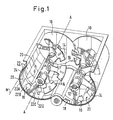
- the double-shaft compulsory mixer shown by way of example in FIG. 1 comprises a double-chamber mixing trough which is composed of two mixing troughs 10.
- a mixing shaft 12 is arranged in each of the two mixing troughs 10.
- the mixing shafts 12 carry in their central axial section mixing elements 14 in the form of mixing blades, which are arranged in such a way that they convey the mix in the two mixing troughs 10 in opposite directions and at the same time move from mixing trough to mixing trough, while at the ends of the two mixing shafts 12 transfer elements 16 are arranged, which ensure that at the ends of the two mixing troughs 10, the mix is transferred from one mixing trough to the other mixing trough. It is only of interest for the present consideration that the transfer organs 16 have a different angle of attack with respect to the mixing elements 14.
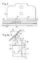
- a mixing trough 10 has a cylindrical inner trough surface 18, which has a circumferential line U and a surface line M.
- the surface line M is parallel to the axis A of the mixing shaft 12.
- the inner trough surface 18 is covered with a tile lining 20.
- the tile lining 20 is formed by wear protection tiles 22.
- the wear protection tiles 22 are arranged in rows of tiles 22A, 22B etc. It can be seen that the wear protection tiles 22 of the rows 22A and 22B are offset from one another, with row butt joints 24 being formed parallel to the surface line M between the rows 22A, 22B etc. and between the individual wear protection tiles 22 of each row of individual tile separating joints 26.
- the single tile parting lines 26 are in the longitudinal direction, i. H. offset from each other in the generatrix line direction M and measured by half the length of a wear protection tile in the generatrix line direction M.
- the wear protection tiles 22 were arranged such that the individual tile separating joints 26 were aligned with one another, in contrast to the offset arrangement according to FIG. 1.
- the mixing elements 14 are arranged with their mixing element edges 28 at an angle ⁇ against the surface line M.
- the peripheral speed of the edge of the mixer organ is designated v u .
- v u The peripheral speed of the edge of the mixer organ.
- v g The resulting speed of the mixed material at the location X of the mixing organ edge 28 is denoted by v r .
- This resulting speed v r results from vectorial superimposition of the peripheral speed v u and the sliding speed v g , the size of which in turn is dependent on the angle of attack ⁇ and on the coefficient of friction of the material to be mixed along the edge of the mixing element 28.
- 2a also shows the normal line N to the single tile separating joint 26.
- the angle enclosed between the normal line N and the speed vector v r of the resulting speed is denoted by ⁇ . It can be seen that, assuming an angle of attack ⁇ of approximately 45 ° and given the circumferential speed v u and the sliding speed v g, the angle ⁇ between the normal line N and the resulting speed vector v r is considerably greater than 45 °.
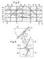
- the wear protection tiles 22 are again arranged in rows 22A, 22B, etc., the row separating joints 24 again running parallel to the surface line M.
- the tiles 22 within the individual rows 22A, 22B etc. are now offset by half their length in the direction of the surface line, so that the individual tile parting lines 26 in the direction of the surface line M are mutually offset are offset, as also indicated in Fig. 4.
- the inclination ⁇ of the resulting speed v r compared to the normal N on the single tile butt joint 26 has now remained the same as in the known embodiment according to FIG. 2a.
- the individual tile separating joints 26 are inclined at an angle ⁇ with respect to the circumferential line U, as shown in FIG. 6.
- the pronounced line movement takes place along the individual tile separating joints 26 and the material is pushed essentially vertically over the individual tile separating joint 26 through the mixing organ edge 28. It has been shown that in this way the leveling out along the individual tile separating joint 26 which occurred in the prior art according to FIG. 2 and the resulting damage to the mixing organ edge 28 is further reduced.
- the offset of the individual tiles 22 in the longitudinal direction of the row, ie in the direction of Surface line M is equal to the projection p of a single tile separating joint 26 onto a row separating joint 24.
- compensation tiles 34 are provided, the end edges 36 of which extend transversely to the surface line M and form a 90 ° angle with the surface line. It can also be seen from FIG. 5 that a single type of compensating tile 34 can be used at both ends of the rows 22A, 22B etc.
- the improvement is achieved only by the offset of the individual tile separating joints by the dimension p in the surface line direction M, which is also present here. You then have the advantage that you can get by with a single normal tile and with a single compensation tile. If the individual tile separating joints located in the area of the transfer members 16 are worn out prematurely and thus a loss of service life occurs, the advantage still remains that one can in the larger area of the mixing members 14 (see Fig. 1) the wear protection tiles 22 are maintained longer and thus the extent of the necessary replacement repair remains reduced.
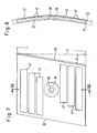
- a normal tile 22 for the embodiment of FIGS. 5 and 6 is shown.
- the angle of the individual tile separating joint 26 against the circumferential line direction U is drawn in with ⁇ and is assumed to be approximately 9 °.
- the normal tile 22 has a projecting central contact surface 38 in the area of a central fastening opening 40 on its rear side. It can also be seen that the normal tile 22 is designed with recesses 42 on the back.
- the compensation tile 34 shown in FIG. 9 is designed accordingly.
- the row parting line 24 is designed as a parallel gap which extends from the inner surface of the tile lining to the inner surface of the cylindrical trough.
- the mounting holes 40 are arranged in the corner points of a rectangular grid.
- compensation tiles are designated by 23 there.
- These compensation tiles 23 have in the row longitudinal direction, i. H. in the surface line direction M half the length as the normal tiles 22.
Landscapes
- Chemical & Material Sciences (AREA)
- Chemical Kinetics & Catalysis (AREA)
- Mixers Of The Rotary Stirring Type (AREA)
- Accessories For Mixers (AREA)
- Confectionery (AREA)
- External Artificial Organs (AREA)
- Processing Of Solid Wastes (AREA)
- Preparation Of Clay, And Manufacture Of Mixtures Containing Clay Or Cement (AREA)
Priority Applications (1)
| Application Number | Priority Date | Filing Date | Title |
|---|---|---|---|
| AT87103699T ATE64546T1 (de) | 1986-03-26 | 1987-03-13 | Mischer. |
Applications Claiming Priority (2)
| Application Number | Priority Date | Filing Date | Title |
|---|---|---|---|
| DE19863610319 DE3610319A1 (de) | 1986-03-26 | 1986-03-26 | Mischer |
| DE3610319 | 1986-03-26 |
Publications (3)
| Publication Number | Publication Date |
|---|---|
| EP0241723A2 true EP0241723A2 (fr) | 1987-10-21 |
| EP0241723A3 EP0241723A3 (en) | 1989-04-12 |
| EP0241723B1 EP0241723B1 (fr) | 1991-06-19 |
Family
ID=6297372
Family Applications (1)
| Application Number | Title | Priority Date | Filing Date |
|---|---|---|---|
| EP87103699A Expired - Lifetime EP0241723B1 (fr) | 1986-03-26 | 1987-03-13 | Mélangeur |
Country Status (5)
| Country | Link |
|---|---|
| EP (1) | EP0241723B1 (fr) |
| JP (1) | JPS62237933A (fr) |
| AT (1) | ATE64546T1 (fr) |
| DE (2) | DE3610319A1 (fr) |
| ES (1) | ES2023130B3 (fr) |
Cited By (12)
| Publication number | Priority date | Publication date | Assignee | Title |
|---|---|---|---|---|
| EP0676235A1 (fr) * | 1994-04-05 | 1995-10-11 | ELBA-WERK Maschinen-Gesellschaft mbH & Co. | Revêtement anti-usure pour un mélangeur à bac des matériau de construction |
| EP0850684A3 (fr) * | 1996-12-31 | 1998-07-08 | BHS-Sonthofen Maschinen- und Anlagenbau GmbH | Revêtement carrelé de la surface intérieur cylindrique d'un mélangeur |
| EP0856354A3 (fr) * | 1997-01-29 | 1998-09-02 | Heissenberger & Pretzler Ges.m.b.H. | Dispositif pour le traitement des déchets organiques |
| DE19856622A1 (de) * | 1998-12-08 | 2000-06-15 | Bhs Sonthofen Maschinen & Anlagenbau Gmbh | Mischer und Mischschaufel |
| GB2362113A (en) * | 2000-05-08 | 2001-11-14 | Gaia Co Ltd | Heated agitator for crushing colloidal fermented garbage |
| WO2002076596A1 (fr) * | 2001-03-28 | 2002-10-03 | Bhs-Sonthofen Maschinen- Und Anlagenbau Gmbh | Revetement de melangeur presentant un certain profil d'usure |
| WO2003097225A1 (fr) * | 2002-05-17 | 2003-11-27 | Bhs-Sonthofen Gmbh | Ailette laterale, melangeur a arbre double dote d'une ailette laterale |
| AU2006200735B2 (en) * | 2005-03-03 | 2011-05-19 | Metso Outotec Finland Oy | Wear Protection System |
| CN102438925A (zh) * | 2009-03-09 | 2012-05-02 | 布赖恩投资有限公司 | 磨耗板 |
| EP3608014A1 (fr) | 2018-08-07 | 2020-02-12 | Pioonier GmbH | Mélangeur thermocinétique destiné au mélange à l'état fondu des produits déchets en matière plastique |
| WO2021155875A1 (fr) | 2020-02-04 | 2021-08-12 | Reimund Dann | Mélangeur thermocinétique pour mélanger à l'état fondu des déchets de plastique |
| US20210252741A1 (en) * | 2020-02-14 | 2021-08-19 | RockSolid Concrete Products Inc. | Mobile twin shaft mixer and methods for use thereof |
Families Citing this family (1)
| Publication number | Priority date | Publication date | Assignee | Title |
|---|---|---|---|---|
| CA2974304C (fr) * | 2015-01-19 | 2021-01-26 | Flsmidth A/S | Systeme de panneaux resistant a l'usure avec imbrication |
Family Cites Families (6)
| Publication number | Priority date | Publication date | Assignee | Title |
|---|---|---|---|---|
| US1591938A (en) * | 1922-11-18 | 1926-07-06 | Allis Chalmers Mfg Co | Liner fastening |
| GB257218A (en) * | 1926-07-06 | 1926-08-26 | Smidth & Co As F L | Improvements in liners for tube and like mills |
| DE1237936B (de) * | 1963-12-06 | 1967-03-30 | Elba Werk Maschinen Gmbh & Co | Verschleissschutz fuer Baustoffmischer, insbesondere Trogmischer |
| US3619439A (en) * | 1969-02-07 | 1971-11-09 | Champion Spark Plug Co | Method of making a brick with wear indicator |
| DE2351771C2 (de) * | 1973-10-16 | 1985-08-01 | Schmelzbasaltwerk Kalenborn - Dr.-Ing. Mauritz KG, 5461 Vettelschoß | Befestigungsausbildung für das Halten von Verschleißauflageplatten, insbesondere für Schachtwendeln |
| US4046326A (en) * | 1975-11-06 | 1977-09-06 | Minneapolis Electric Steel Castings Company | Shell liner assembly |
-
1986
- 1986-03-26 DE DE19863610319 patent/DE3610319A1/de active Granted
-
1987
- 1987-03-13 EP EP87103699A patent/EP0241723B1/fr not_active Expired - Lifetime
- 1987-03-13 AT AT87103699T patent/ATE64546T1/de not_active IP Right Cessation
- 1987-03-13 DE DE8787103699T patent/DE3770856D1/de not_active Expired - Lifetime
- 1987-03-13 ES ES87103699T patent/ES2023130B3/es not_active Expired - Lifetime
- 1987-03-26 JP JP62070554A patent/JPS62237933A/ja active Granted
Cited By (18)
| Publication number | Priority date | Publication date | Assignee | Title |
|---|---|---|---|---|
| EP0676235A1 (fr) * | 1994-04-05 | 1995-10-11 | ELBA-WERK Maschinen-Gesellschaft mbH & Co. | Revêtement anti-usure pour un mélangeur à bac des matériau de construction |
| EP0677324A1 (fr) * | 1994-04-05 | 1995-10-18 | ELBA-WERK Maschinen-Gesellschaft mbH & Co. | Revêtement anti-usure pour un mélangeur à bac de matériaux de construction avec des plaques d'usure haubanées à la manière d'un arc de support |
| EP0850684A3 (fr) * | 1996-12-31 | 1998-07-08 | BHS-Sonthofen Maschinen- und Anlagenbau GmbH | Revêtement carrelé de la surface intérieur cylindrique d'un mélangeur |
| EP0856354A3 (fr) * | 1997-01-29 | 1998-09-02 | Heissenberger & Pretzler Ges.m.b.H. | Dispositif pour le traitement des déchets organiques |
| DE19856622A1 (de) * | 1998-12-08 | 2000-06-15 | Bhs Sonthofen Maschinen & Anlagenbau Gmbh | Mischer und Mischschaufel |
| DE19856622C2 (de) * | 1998-12-08 | 2001-11-15 | Bhs Sonthofen Maschinen & Anlagenbau Gmbh | Mischer und Mischorgan |
| GB2362113A (en) * | 2000-05-08 | 2001-11-14 | Gaia Co Ltd | Heated agitator for crushing colloidal fermented garbage |
| GB2362113B (en) * | 2000-05-08 | 2002-06-19 | Gaia Co Ltd | Agitator |
| WO2002076596A1 (fr) * | 2001-03-28 | 2002-10-03 | Bhs-Sonthofen Maschinen- Und Anlagenbau Gmbh | Revetement de melangeur presentant un certain profil d'usure |
| WO2003097225A1 (fr) * | 2002-05-17 | 2003-11-27 | Bhs-Sonthofen Gmbh | Ailette laterale, melangeur a arbre double dote d'une ailette laterale |
| CN1305554C (zh) * | 2002-05-17 | 2007-03-21 | Bhs桑托芬有限公司 | 侧向叶片以及包含侧向叶片的双轴混合机 |
| AU2006200735B2 (en) * | 2005-03-03 | 2011-05-19 | Metso Outotec Finland Oy | Wear Protection System |
| CN102438925A (zh) * | 2009-03-09 | 2012-05-02 | 布赖恩投资有限公司 | 磨耗板 |
| EP3608014A1 (fr) | 2018-08-07 | 2020-02-12 | Pioonier GmbH | Mélangeur thermocinétique destiné au mélange à l'état fondu des produits déchets en matière plastique |
| DE102018119218B4 (de) | 2018-08-07 | 2025-01-09 | Pioonier GmbH | Thermokinetischer Mischer zum Schmelzmischen von Kunststoffabfallprodukten |
| WO2021155875A1 (fr) | 2020-02-04 | 2021-08-12 | Reimund Dann | Mélangeur thermocinétique pour mélanger à l'état fondu des déchets de plastique |
| US20210252741A1 (en) * | 2020-02-14 | 2021-08-19 | RockSolid Concrete Products Inc. | Mobile twin shaft mixer and methods for use thereof |
| US12036699B2 (en) * | 2020-02-14 | 2024-07-16 | RockSolid Concrete Products Inc. | Mobile twin shaft mixers formed of a flexible sheath and methods for use thereof |
Also Published As
| Publication number | Publication date |
|---|---|
| JPS62237933A (ja) | 1987-10-17 |
| ES2023130B3 (es) | 1992-01-01 |
| DE3610319A1 (de) | 1987-10-01 |
| ATE64546T1 (de) | 1991-07-15 |
| JPH046414B2 (fr) | 1992-02-05 |
| EP0241723B1 (fr) | 1991-06-19 |
| EP0241723A3 (en) | 1989-04-12 |
| DE3610319C2 (fr) | 1989-05-03 |
| DE3770856D1 (en) | 1991-07-25 |
Similar Documents
| Publication | Publication Date | Title |
|---|---|---|
| EP0241723B1 (fr) | Mélangeur | |
| EP1278594B1 (fr) | Malaxeur a melange force a deux arbres, son utilisation et procede pour faire fonctionner un malaxeur a melange force a deux arbres | |
| DE2113182C3 (de) | Misch- und Knetmaschine | |
| DE3344531A1 (de) | Mischvorrichtung | |
| EP0422272B1 (fr) | Dispositif de malaxage et pétrissage | |
| DE2822778A1 (de) | Mischvorrichtung | |
| DE211789C (fr) | ||
| DE19703495C2 (de) | Trogmischer | |
| EP0584151B1 (fr) | Outil melangeur | |
| DE3144305C2 (de) | Vorrichtung zum Mischen von körnigem oder pulverförmigem Material | |
| DE8634964U1 (de) | Verschleißschutzkachelsatz für die Auskleidung eines Mischtrogs | |
| DE2953699C2 (de) | Mischer, insbesondere Betonmischer | |
| DE8608356U1 (de) | Mischer | |
| DE4206219A1 (de) | Vorrichtung zum mischen und/oder kneten von werkstoffen | |
| DE2339058A1 (de) | Rost fuer eine muehle oder eine andere verarbeitungsanlage | |
| DE8634963U1 (de) | Viereckige Verschleißschutzkachel für die Auskleidung eines Mischtrogs | |
| DD266465A3 (de) | Vorrichtung zum mischen | |
| DE3715542C1 (fr) | ||
| DE2710215B1 (de) | Vorrichtung zum kontinuierlichen Herstellen von Moertel o.dgl. | |
| DE3311715A1 (de) | Klumpenbrecher | |
| DE19810649C2 (de) | Vorrichtung zum Behandeln von Papierfaserstoffen | |
| DE2012689A1 (en) | Double conical rotating drum blender | |
| AT390594B (de) | Kettenfoerderer | |
| DE19800195A1 (de) | Vorrichtung zum Behandeln von fließfähigen Massen | |
| DE29503018U1 (de) | Mischer, nämlich Tellermischer bzw. Ringtellermischer |
Legal Events
| Date | Code | Title | Description |
|---|---|---|---|
| PUAI | Public reference made under article 153(3) epc to a published international application that has entered the european phase |
Free format text: ORIGINAL CODE: 0009012 |
|
| 17P | Request for examination filed |
Effective date: 19870313 |
|
| AK | Designated contracting states |
Kind code of ref document: A2 Designated state(s): AT BE CH DE ES FR IT LI NL SE |
|
| PUAL | Search report despatched |
Free format text: ORIGINAL CODE: 0009013 |
|
| AK | Designated contracting states |
Kind code of ref document: A3 Designated state(s): AT BE CH DE ES FR IT LI NL SE |
|
| 17Q | First examination report despatched |
Effective date: 19900920 |
|
| GRAA | (expected) grant |
Free format text: ORIGINAL CODE: 0009210 |
|
| AK | Designated contracting states |
Kind code of ref document: B1 Designated state(s): AT BE CH DE ES FR IT LI NL SE |
|
| REF | Corresponds to: |
Ref document number: 64546 Country of ref document: AT Date of ref document: 19910715 Kind code of ref document: T |
|
| ITF | It: translation for a ep patent filed | ||
| REF | Corresponds to: |
Ref document number: 3770856 Country of ref document: DE Date of ref document: 19910725 |
|
| ET | Fr: translation filed | ||
| REG | Reference to a national code |
Ref country code: ES Ref legal event code: FG2A Ref document number: 2023130 Country of ref document: ES Kind code of ref document: B3 |
|
| PLBE | No opposition filed within time limit |
Free format text: ORIGINAL CODE: 0009261 |
|
| STAA | Information on the status of an ep patent application or granted ep patent |
Free format text: STATUS: NO OPPOSITION FILED WITHIN TIME LIMIT |
|
| 26N | No opposition filed | ||
| EAL | Se: european patent in force in sweden |
Ref document number: 87103699.2 |
|
| REG | Reference to a national code |
Ref country code: CH Ref legal event code: PUE Owner name: SKW TROSTBERG AKTIENGESELLSCHAFT TRANSFER- BHS-SON Ref country code: CH Ref legal event code: PFA Free format text: BHS - BAYERISCHE BERG-, HUETTEN- UND SALZWERKE AKTIENGESELLSCHAFT TRANSFER- SKW TROSTBERG AKTIENGESELLSCHAFT |
|
| PGFP | Annual fee paid to national office [announced via postgrant information from national office to epo] |
Ref country code: FR Payment date: 20040126 Year of fee payment: 18 |
|
| PGFP | Annual fee paid to national office [announced via postgrant information from national office to epo] |
Ref country code: NL Payment date: 20040227 Year of fee payment: 18 |
|
| PGFP | Annual fee paid to national office [announced via postgrant information from national office to epo] |
Ref country code: SE Payment date: 20040302 Year of fee payment: 18 |
|
| PGFP | Annual fee paid to national office [announced via postgrant information from national office to epo] |
Ref country code: AT Payment date: 20040303 Year of fee payment: 18 |
|
| PGFP | Annual fee paid to national office [announced via postgrant information from national office to epo] |
Ref country code: CH Payment date: 20040308 Year of fee payment: 18 |
|
| PGFP | Annual fee paid to national office [announced via postgrant information from national office to epo] |
Ref country code: ES Payment date: 20040319 Year of fee payment: 18 |
|
| PGFP | Annual fee paid to national office [announced via postgrant information from national office to epo] |
Ref country code: BE Payment date: 20040512 Year of fee payment: 18 |
|
| PG25 | Lapsed in a contracting state [announced via postgrant information from national office to epo] |
Ref country code: AT Free format text: LAPSE BECAUSE OF NON-PAYMENT OF DUE FEES Effective date: 20050313 |
|
| PG25 | Lapsed in a contracting state [announced via postgrant information from national office to epo] |
Ref country code: SE Free format text: LAPSE BECAUSE OF NON-PAYMENT OF DUE FEES Effective date: 20050314 Ref country code: ES Free format text: LAPSE BECAUSE OF NON-PAYMENT OF DUE FEES Effective date: 20050314 |
|
| PG25 | Lapsed in a contracting state [announced via postgrant information from national office to epo] |
Ref country code: LI Free format text: LAPSE BECAUSE OF NON-PAYMENT OF DUE FEES Effective date: 20050331 Ref country code: CH Free format text: LAPSE BECAUSE OF NON-PAYMENT OF DUE FEES Effective date: 20050331 Ref country code: BE Free format text: LAPSE BECAUSE OF NON-PAYMENT OF DUE FEES Effective date: 20050331 |
|
| BERE | Be: lapsed |
Owner name: *BHS-BAYERISCHE BERG-, HUTTEN- UND SALZWERKE A.G. Effective date: 20050331 |
|
| PG25 | Lapsed in a contracting state [announced via postgrant information from national office to epo] |
Ref country code: NL Free format text: LAPSE BECAUSE OF NON-PAYMENT OF DUE FEES Effective date: 20051001 |
|
| EUG | Se: european patent has lapsed | ||
| REG | Reference to a national code |
Ref country code: CH Ref legal event code: PL |
|
| PG25 | Lapsed in a contracting state [announced via postgrant information from national office to epo] |
Ref country code: FR Free format text: LAPSE BECAUSE OF NON-PAYMENT OF DUE FEES Effective date: 20051130 |
|
| NLV4 | Nl: lapsed or anulled due to non-payment of the annual fee |
Effective date: 20051001 |
|
| PGFP | Annual fee paid to national office [announced via postgrant information from national office to epo] |
Ref country code: DE Payment date: 20051215 Year of fee payment: 20 |
|
| REG | Reference to a national code |
Ref country code: FR Ref legal event code: ST Effective date: 20051130 |
|
| PGFP | Annual fee paid to national office [announced via postgrant information from national office to epo] |
Ref country code: IT Payment date: 20060331 Year of fee payment: 20 |
|
| REG | Reference to a national code |
Ref country code: ES Ref legal event code: FD2A Effective date: 20050314 |
|
| BERE | Be: lapsed |
Owner name: *BHS-BAYERISCHE BERG-, HUTTEN- UND SALZWERKE A.G. Effective date: 20050331 |