EP0241723A2 - Mixer - Google Patents
Mixer Download PDFInfo
- Publication number
- EP0241723A2 EP0241723A2 EP87103699A EP87103699A EP0241723A2 EP 0241723 A2 EP0241723 A2 EP 0241723A2 EP 87103699 A EP87103699 A EP 87103699A EP 87103699 A EP87103699 A EP 87103699A EP 0241723 A2 EP0241723 A2 EP 0241723A2
- Authority
- EP
- European Patent Office
- Prior art keywords
- joints
- trough
- tiles
- individual tile
- mixing
- Prior art date
- Legal status (The legal status is an assumption and is not a legal conclusion. Google has not performed a legal analysis and makes no representation as to the accuracy of the status listed.)
- Granted
Links
Images


Classifications
-
- B—PERFORMING OPERATIONS; TRANSPORTING
- B01—PHYSICAL OR CHEMICAL PROCESSES OR APPARATUS IN GENERAL
- B01F—MIXING, e.g. DISSOLVING, EMULSIFYING OR DISPERSING
- B01F35/00—Accessories for mixers; Auxiliary operations or auxiliary devices; Parts or details of general application
- B01F35/50—Mixing receptacles
- B01F35/511—Mixing receptacles provided with liners, e.g. wear resistant or flexible liners
Definitions
- the invention relates to a mixer with at least one mixing shaft comprising a mixing trough with an approximately cylindrical inner trough surface occupied by wear protection tiles and at least one mixing element lying adjacent to the trough inner surface and rotating around the mixing trough axis with one of the lining organ surfaces approximately formed by the wear protection tiles and following an angle of attack against has a surface line of the lining inner surface which is parallel to the mixer axis and intersects the edge of the mixer organ, the wear protection tiles being arranged in rows which are approximately parallel to the surface line approximately mutually parallel line separating joints between adjacent rows and with individual tile separating joints extending at an angle to the row separating joints are arranged between the individual tiles of each row.
- Such a mixer is known for example from DE-PS 12 37 936.
- the wear protection tiles are generally interchangeable and can be replaced as intended after wear, so that the mixing trough construction is retained.
- Such trough linings are used in particular in compulsory mixers for mixing powdery, granular and plastic materials, for. B. in mixers for processing building material mixtures.
- the wear protection tiles are designed with a rectangular outline, the individual tile separating joints of adjacent rows lying in circumferential alignment with one another.
- the invention has for its object to design a mixer of the type mentioned in such a way that the premature wear of the individual tile separating joints running transverse to the longitudinal direction of the tile lining is largely avoided.
- the individual tile joints are perpendicular to the row joints. If you then additionally ensure that the individual tile separating joints of adjacent rows are offset by half the individual tile dimensions in the row longitudinal direction, you can get by with a single type of compensation pieces, namely compensation pieces whose length in the row longitudinal direction is equal to half the tile length in the row longitudinal direction .
- the individual tile separating joints are inclined against a circumferential line
- an interruption of the line flow along the individual tile separating joints is achieved and, on the other hand, this measure ensures that an inner trough surface can be lined with a single compensating tile in addition to the normal tiles.
- the leveling tile then differs from the normal tiles only in that one of its end edges running transverse to the longitudinal direction of the row runs parallel to the associated circumferential line.
- the wear protection tiles can rest against the inner surface of the trough in an abutment area surrounding an approximately central fastening point and can have a short, approximately constant distance from the inner surface of the trough outside this abutment area.
- This embodiment ensures that when the wear protection tile is fastened, for example by means of a clamping screw, no bending stresses can be introduced into the tile. however, it is possible to support the tiles on the inner surface of the trough.
- the tiles on their outer surfaces i. H. those areas that lie against the inner surface of the trough be provided with recesses.
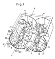
- the double-shaft compulsory mixer shown by way of example in FIG. 1 comprises a double-chamber mixing trough which is composed of two mixing troughs 10.
- a mixing shaft 12 is arranged in each of the two mixing troughs 10.
- the mixing shafts 12 carry in their central axial section mixing elements 14 in the form of mixing blades, which are arranged in such a way that they convey the mix in the two mixing troughs 10 in opposite directions and at the same time move from mixing trough to mixing trough, while at the ends of the two mixing shafts 12 transfer elements 16 are arranged, which ensure that at the ends of the two mixing troughs 10, the mix is transferred from one mixing trough to the other mixing trough. It is only of interest for the present consideration that the transfer organs 16 have a different angle of attack with respect to the mixing elements 14.
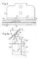
- a mixing trough 10 has a cylindrical inner trough surface 18, which has a circumferential line U and a surface line M.
- the surface line M is parallel to the axis A of the mixing shaft 12.
- the inner trough surface 18 is covered with a tile lining 20.
- the tile lining 20 is formed by wear protection tiles 22.
- the wear protection tiles 22 are arranged in rows of tiles 22A, 22B etc. It can be seen that the wear protection tiles 22 of the rows 22A and 22B are offset from one another, with row butt joints 24 being formed parallel to the surface line M between the rows 22A, 22B etc. and between the individual wear protection tiles 22 of each row of individual tile separating joints 26.
- the single tile parting lines 26 are in the longitudinal direction, i. H. offset from each other in the generatrix line direction M and measured by half the length of a wear protection tile in the generatrix line direction M.
- the wear protection tiles 22 were arranged such that the individual tile separating joints 26 were aligned with one another, in contrast to the offset arrangement according to FIG. 1.
- the mixing elements 14 are arranged with their mixing element edges 28 at an angle ⁇ against the surface line M.
- the peripheral speed of the edge of the mixer organ is designated v u .
- v u The peripheral speed of the edge of the mixer organ.
- v g The resulting speed of the mixed material at the location X of the mixing organ edge 28 is denoted by v r .
- This resulting speed v r results from vectorial superimposition of the peripheral speed v u and the sliding speed v g , the size of which in turn is dependent on the angle of attack ⁇ and on the coefficient of friction of the material to be mixed along the edge of the mixing element 28.
- 2a also shows the normal line N to the single tile separating joint 26.
- the angle enclosed between the normal line N and the speed vector v r of the resulting speed is denoted by ⁇ . It can be seen that, assuming an angle of attack ⁇ of approximately 45 ° and given the circumferential speed v u and the sliding speed v g, the angle ⁇ between the normal line N and the resulting speed vector v r is considerably greater than 45 °.
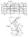
- the wear protection tiles 22 are again arranged in rows 22A, 22B, etc., the row separating joints 24 again running parallel to the surface line M.
- the tiles 22 within the individual rows 22A, 22B etc. are now offset by half their length in the direction of the surface line, so that the individual tile parting lines 26 in the direction of the surface line M are mutually offset are offset, as also indicated in Fig. 4.
- the inclination ⁇ of the resulting speed v r compared to the normal N on the single tile butt joint 26 has now remained the same as in the known embodiment according to FIG. 2a.
- the individual tile separating joints 26 are inclined at an angle ⁇ with respect to the circumferential line U, as shown in FIG. 6.
- the pronounced line movement takes place along the individual tile separating joints 26 and the material is pushed essentially vertically over the individual tile separating joint 26 through the mixing organ edge 28. It has been shown that in this way the leveling out along the individual tile separating joint 26 which occurred in the prior art according to FIG. 2 and the resulting damage to the mixing organ edge 28 is further reduced.
- the offset of the individual tiles 22 in the longitudinal direction of the row, ie in the direction of Surface line M is equal to the projection p of a single tile separating joint 26 onto a row separating joint 24.
- compensation tiles 34 are provided, the end edges 36 of which extend transversely to the surface line M and form a 90 ° angle with the surface line. It can also be seen from FIG. 5 that a single type of compensating tile 34 can be used at both ends of the rows 22A, 22B etc.
- the improvement is achieved only by the offset of the individual tile separating joints by the dimension p in the surface line direction M, which is also present here. You then have the advantage that you can get by with a single normal tile and with a single compensation tile. If the individual tile separating joints located in the area of the transfer members 16 are worn out prematurely and thus a loss of service life occurs, the advantage still remains that one can in the larger area of the mixing members 14 (see Fig. 1) the wear protection tiles 22 are maintained longer and thus the extent of the necessary replacement repair remains reduced.
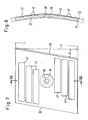
- a normal tile 22 for the embodiment of FIGS. 5 and 6 is shown.
- the angle of the individual tile separating joint 26 against the circumferential line direction U is drawn in with ⁇ and is assumed to be approximately 9 °.
- the normal tile 22 has a projecting central contact surface 38 in the area of a central fastening opening 40 on its rear side. It can also be seen that the normal tile 22 is designed with recesses 42 on the back.
- the compensation tile 34 shown in FIG. 9 is designed accordingly.
- the row parting line 24 is designed as a parallel gap which extends from the inner surface of the tile lining to the inner surface of the cylindrical trough.
- the mounting holes 40 are arranged in the corner points of a rectangular grid.
- compensation tiles are designated by 23 there.
- These compensation tiles 23 have in the row longitudinal direction, i. H. in the surface line direction M half the length as the normal tiles 22.
Landscapes
- Chemical & Material Sciences (AREA)
- Chemical Kinetics & Catalysis (AREA)
- Mixers Of The Rotary Stirring Type (AREA)
- Accessories For Mixers (AREA)
- Confectionery (AREA)
- External Artificial Organs (AREA)
- Processing Of Solid Wastes (AREA)
- Preparation Of Clay, And Manufacture Of Mixtures Containing Clay Or Cement (AREA)
Abstract
Es wird vorgeschlagen, bei einer Kachelauskleidung für den zylindrischen Mischtrog einer Mischers die Einzelkacheln (22) benachbarter, in Mantellinienrichtung verlaufender Kachelreihen (22B, 22C. 22D) in dieser Mantellinienrichtung (M) gegeneinander zu versetzen. 
Description
Die Erfindung betrifft einen Mischer mit mindestens einer Mischwelle umfassend einen Mischtrog mit einer von Verschleißschutzkacheln belegten, annähernd zylindrischen Troginnenfläche und mindestens ein der Troginnenfläche benachbart liegendes, um die Mischtrogachse umlaufendes Mischorgan mit einer der von den Verschleißschutzkacheln gebildeten Auskleidungsinnenfläche angenähert folgenden Mischorgankante, welche einen Anstellwinkel gegen eine zur Mischerachse parallele, die Mischorgankante schneidende Mantellinie der Auskleidungsinnenfläche aufweist, wobei die Verschleißschutzkacheln in annähernd mantellinienparallelen Reihen mit annähernd mantellinienparallelen Reihentrennfugen zwischen benachbarten Reihen und mit unter einem Winkel zu den Reihentrennfugen verlaufenden Einzelkacheltrennfugen zwischen den Einzelkacheln jeder Reihe angeordnet sind.The invention relates to a mixer with at least one mixing shaft comprising a mixing trough with an approximately cylindrical inner trough surface occupied by wear protection tiles and at least one mixing element lying adjacent to the trough inner surface and rotating around the mixing trough axis with one of the lining organ surfaces approximately formed by the wear protection tiles and following an angle of attack against has a surface line of the lining inner surface which is parallel to the mixer axis and intersects the edge of the mixer organ, the wear protection tiles being arranged in rows which are approximately parallel to the surface line approximately mutually parallel line separating joints between adjacent rows and with individual tile separating joints extending at an angle to the row separating joints are arranged between the individual tiles of each row.
Ein solcher Mischer ist beispielsweise aus der DE-PS 12 37 936 bekannt. Die Verschleißschutzkacheln sind in der Regel austauschbar und können nach eingetretenem Verschleiß bestimmungsgemäß ausgetauscht werden, so daß die Mischtrogkonstruktion erhalten bleibt. Solche Mischtrogauskleidungen werden insbesondere bei Zwangsmischern zum Vermischen von pulvrigen, körnigen und plastischen Mischgütern angewandet, z. B. bei Mischern zum Verarbeiten von Baustoffmischungen.Such a mixer is known for example from DE-PS 12 37 936. The wear protection tiles are generally interchangeable and can be replaced as intended after wear, so that the mixing trough construction is retained. Such trough linings are used in particular in compulsory mixers for mixing powdery, granular and plastic materials, for. B. in mixers for processing building material mixtures.
Bei der bekannten Ausführungsform nach der DE-PS 12 37 936 sind die Verschleißschutzkacheln mit rechteckigem Umriß ausgebildet, wobei die Einzelkacheltrennfugen benachbarter Reihen in Umfangsflucht miteinander liegen.In the known embodiment according to DE-PS 12 37 936, the wear protection tiles are designed with a rectangular outline, the individual tile separating joints of adjacent rows lying in circumferential alignment with one another.
Es wurde nun festgestellt, daß bei der bekannten Ausführungsform an den Einzelkacheltrennfugen ein rascherer Verschleiß eintritt als an den in Mantellinienrichtung liegenden Reihentrennfugen und als an den die Auskleidungsinnenfläche bildenden Innenflächen der Kacheln.It has now been found that, in the known embodiment, wear occurs more rapidly on the individual tile separating joints than on the row separating joints lying in the direction of the surface line and on the inner surfaces of the tiles forming the lining inner surface.
Der Erfindung liegt die Aufgabe zugrunde, einen Mischer der eingangs bezeichneten Art so auszugestalten, daß der vorzeitige Verschleiß der quer zur Reihenlängsrichtung der Kachelauskleidung verlaufenden Einzelkacheltrennfugen weitgehend vermieden wird.The invention has for its object to design a mixer of the type mentioned in such a way that the premature wear of the individual tile separating joints running transverse to the longitudinal direction of the tile lining is largely avoided.
Zur Lösung dieser Aufgabe wird vorgeschlagen, daß die Einzelkacheltrennfugen einzelner Reihen gegen die Einzel kacheltrennfugen anderer Reihen in Reihenlängsrichtung, d. h. in Mantellinienrichtung versetzt sind.To solve this problem it is proposed that the individual tile joints of individual rows against the individual Tile dividing joints of other rows in the row longitudinal direction, ie are offset in the surface line direction.
Es wurde gefunden, daß durch diese Maßnahme der Verschleiß der Kacheln im Bereich der Einzelkacheltrennfugen wesentlich vermindert werden kann. Die Ursache für diesen vorteilhaften Effekt ist nicht voll geklärt. Es könnte sein, daß dieser vorteilhafte Effekt darauf zurückzuführen ist, daß der Linientransport von Mischgut längs der Einzelkacheltrennfugen durch deren Versatz im Bereich aufeinanderfolgender Reihentrennfugen unterbrochen wird und damit die abrasive Wirkung des Mischguts auf die die Einzelkacheltrennfugen bildenden Bereiche der Kacheln herabgesetzt wird. Es hat sich jedenfalls gezeigt, daß durch die versetzte Anordnung der Einzelkacheltrennfugen einzelner Reihen gegenüber den Einzelkacheltrennfugen anderer Reihen die Standzeit sämtlicher Kachelbereiche einander angenähert wird und damit die Standzeit der Verschleißschutzkacheln insgesamt verlängert wird.It was found that this measure can significantly reduce the wear on the tiles in the area of the individual tile joints. The cause of this beneficial effect is not fully understood. It could be that this advantageous effect is due to the fact that the line transport of mixed material along the individual tile separating joints is interrupted by their offset in the area of successive row separating joints and thus the abrasive effect of the mixed material on the areas of the tiles forming the individual tile separating joints is reduced. In any case, it has been shown that the staggered arrangement of the individual tile separating joints of individual rows compared to the individual tile separating joints of other rows approximates the service life of all tile areas and thus extends the service life of the wear protection tiles as a whole.
Besonders günstige Ergebnisse hinsichtlich der Standzeitverlängerung werden dann erreicht, wenn die Einzelkacheltrennfugen jeder Reihe gegenüber den Einzelkacheltrennfugen der dieser Reihe unmittelbar benachbarten Reihen in Mantellinienrichtung versetzt sind. Dieses Ergebnis stützt die oben angegebene Theorie, daß die Unterbrechung des Linienflusses des Mischguts längs der Einzelkacheltrennfugen für die Verringerung der Abnutzungserscheinungen an den Kacheln im Bereich der Einzelkacheltrennfugen verantwortlich sein könnte.Particularly favorable results with regard to the extension of the service life are achieved if the individual tile separating joints of each row are offset in the direction of the generatrix in relation to the individual tile separating joints of the rows immediately adjacent to this row. This result supports the theory given above that the interruption of the line flow of the mixed material along the individual tile separating joints could be responsible for the reduction in the wear on the tiles in the area of the individual tile separating joints.
Der Ausführung des Erfindungsgedankens stand die Überlegung entgegen, daß man bei Versetzung der Einzel kacheltrennfugen in Reihenlängsrichtung gegeneinander an den Enden der jeweiligen Reihen Fehlstellen erhalten würde, in denen die Auskleidung unterbrochen ist und daß man dort für eine andere Form der Auskleidung sorgen müßte. Es hat sich aber nun gezeigt, daß sich auch dieses Problem in verhältnismäßig einfacher Weise dadurch lösen läßt, daß an den Enden mindestens eines Teils der Reihen Ausgleichskacheln vorgesehen werden.The execution of the inventive idea was opposed to the consideration that when transferring the individual tile separating joints in the row longitudinal direction against each other at the ends of the respective rows would receive defects in which the lining is interrupted and that one would have to take care of a different form of the lining there. However, it has now been shown that this problem can also be solved in a relatively simple manner by providing compensating tiles at the ends of at least part of the rows.
Nach einem Ausführungsbeispiel der Erfindung stehen die Einzelkacheltrennfugen senkrecht zu den Reihentrennfugen. Wenn man dann noch zusätzlich dafür sorgt, daß die Einzelkacheltrennfugen benachbarter Reihen jeweils um die halbe Einzelkachelabmessung in Reihenlängsrichtung gegeneinander versetzt sind, so kommt man mit einem einzigen Typ von Ausgleichsstücken aus, nämlich Ausgleichsstücken, deren Länge in Reihenlängsrichtung gleich der Hälfte der Kachellänge in Reihenlängsrichtung ist.According to one embodiment of the invention, the individual tile joints are perpendicular to the row joints. If you then additionally ensure that the individual tile separating joints of adjacent rows are offset by half the individual tile dimensions in the row longitudinal direction, you can get by with a single type of compensation pieces, namely compensation pieces whose length in the row longitudinal direction is equal to half the tile length in the row longitudinal direction .
Überraschenderweise hat sich weiter ergeben, daß eine wesentliche Verringerung des Verschleißes der Verschleißschutzkacheln an den Einzelkacheltrennfugen auch dadurch erzielt werden kann, daß die Einzelkacheltrennfugen gegen eine Umfangslinie des Troges geneigt angeordnet werden, und zwar im Sinne einer Verkleinerung des Winkels zwischen dem Geschwindigkeitsvektor der resultierenden Mischgutbewegung im Bereich der Mischorgankante und einer der Auskleidungsinnenfläche folgenden Normallinie auf die jeweilige Einzelkacheltrennfuge. Auch diese Erscheinung ist nicht voll erklärt. Sie könnte darauf zurückzuführen sein, daß durch die Winkelannäherung des Geschwindigkeitsvektros der resultierenden Mischgutbewegung im Bereich der Mischorgankante an eine der Troginnenfläche folgende Normallinie auf die jeweilige Einzelkacheltrennfuge die Linienbewegung des Mischguts längs der jeweiligen Einzelkacheltrennfuge weitgehend unterdrückt wird.Surprisingly, it has also been found that a significant reduction in wear of the wear protection tiles on the individual tile joints can also be achieved in that the individual tile joints are arranged inclined against a circumferential line of the trough, in the sense of a reduction in the angle between the speed vector of the resulting mixture movement in the Area of the mixing organ edge and a normal line following the inner lining surface onto the respective individual tile joint. This phenomenon is also not fully explained. It could be due to the fact that the angular approximation of the speed vector of the resulting mixture movement in the area of the mixer organ edge to a normal line following the inner surface of the trough to the respective one Single tile joint the line movement of the mix along the respective single tile joint is largely suppressed.
Der Gedanke, die Einzelkacheltrennfugen gegen die Umfangslinie der Troginnenfläche zu neigen, soll unabhängig von der Versetzung der Einzelkacheltrennfugen einzelner Reihen gegen die Einzelkacheltrennfugen anderer Reihen in Mantellinienrichtung geschützt werden, d. h. es soll auch insbesondere diejenige Möglichkeit durch den Schutz erfaßt sein, bei der die gegen die Umfangslinie geneigten Einzelkacheltrennfugen aufeinanderfolgender Reihen sämtliche in Flucht miteinander liegen.The idea of inclining the individual tile separating joints against the circumferential line of the inner trough surface should be protected against the individual tile separating joints of other rows in the direction of the generatrix, irrespective of the displacement of the individual tile separating joints. H. in particular, the possibility is to be covered by the protection in which the individual tile separating joints inclined against the circumferential line of successive rows are all in alignment with one another.
Bei der Ausführungsform, bei der die Einzelkacheltrennfugen gegen eine Umfangslinie geneigt sind, empfiehlt es sich, die Einzelkacheltrennfugen jeweils um die Länge ihrer Projektion auf die Reihenlängsfugen gegeneinander in Reihenlängsrichtung zu versetzen. Damit wird zum einen wieder eine Unterbrechung des Linienflusses längs der Einzelkacheltrennfugen erreicht und zum anderen wird durch diese Maßnahme erreicht, daß mit einer einzigen Ausgleichskachel neben den Normalkacheln eine Troginnenfläche ausgekleidet werden kann. Die Ausgleichskachel unterscheidet sich dann von den Normalkacheln nur dadurch, daß die eine ihrer quer zur Reihenlängsrichtung verlaufenden Endkanten parallel zur zugehörigen Umfangslinie verläuft.In the embodiment in which the individual tile separating joints are inclined against a circumferential line, it is advisable to offset the individual tile separating joints from one another in the longitudinal direction of the row by the length of their projection onto the longitudinal longitudinal joints. Thus, on the one hand, an interruption of the line flow along the individual tile separating joints is achieved and, on the other hand, this measure ensures that an inner trough surface can be lined with a single compensating tile in addition to the normal tiles. The leveling tile then differs from the normal tiles only in that one of its end edges running transverse to the longitudinal direction of the row runs parallel to the associated circumferential line.
Bei Ausrüstung des Mischers mit Mischorganen unterschiedlicher Anstellwinkel kann man durch entsprechende Kachelanordnung im Bereich eines jeden Mischorgans einerseits für die Versetzung der Einzelkacheltrennfugen einzelner Reihen gegen die Einzelkacheltrennfugen benachbarter Reihen sorgen und andererseits die Forderung erfüllen, daß die Einzelkacheltrennfugen gegen eine Umfangslinie geneigt sind im Sinne einer Winkelannäherung des Geschwindigkeitsvektors der resultierenden Mischgutbewegung im Bereich der jeweiligen Mischorgankante an eine der Auskleidungsinnenfläche folgende Normallinie auf die jeweilige Einzelkacheltrennfuge. Dies würde zu einer optimalen Standzeit der gesamten Auskleidung führen. Man kann sich aber kompromißweise auch mit einer Lösung abfinden dahin, daß bei Ausrüstung des Mischers mit Mischorganen unterschiedlichen Anstellwinkels die Neigung der Einzelkacheltrennfugen gegen die Umfangslinie für sämtliche Kacheln die gleiche ist und auf den Anstellwinkel der in größter Zahl vorhandenen Mischorgane gleichen Anstellwinkels abgestimmt ist. Diese Lösung kann man beispielsweise wählen, wenn bei einem Doppelwellenzwangsmischer an den beiden Enden jeder Welle Materialüberführungsorgane zur Mischgutüberführung von dem Bereich der einen Welle in den Bereich der anderen Welle vorgesehen sind und diese Überführungsorgane eine den normalen Mischorganen entgegengesetzte Anstellwinkelneigung besitzen. Auf jeden Fall kann auch dann, wenn der Mischer mit Misch- oder Überführungsorganen unterschiedlichen Anstellwinkels ausgerüstet ist, der Vorteil ausgenutzt werden, der sich aus der Versetzung der Einzelkacheltrennfugen aufeinanderfolgender Reihen in Reihenlängsrichtung gegeneinander ergibt.When equipping the mixer with mixing elements with different angles of attack, appropriate tile arrangements in the area of each mixing element can on the one hand ensure the displacement of the individual tile separating joints of individual rows against the individual tile separating joints of adjacent rows and, on the other hand, meet the requirement that the individual tile separating joints are inclined in the sense of a circumferential line Angle approximation of the speed vector of the resulting mixture movement in the area of the respective mixer organ edge to a normal line following the inner lining surface onto the respective individual tile joint. This would lead to an optimal service life of the entire lining. However, one can also compromise with a solution to the fact that when the mixer is equipped with mixing elements with different angles of attack, the inclination of the individual tile separating joints against the circumferential line is the same for all tiles and is matched to the angle of attack of the large number of mixing elements with the same angle of attack. This solution can be chosen, for example, if material transfer devices for transferring the mix from the area of one shaft to the area of the other shaft are provided at the two ends of each shaft in a double-shaft compulsory mixer and these transfer devices have a pitch angle opposite to that of the normal mixing devices. In any case, even if the mixer is equipped with mixing or transfer elements of different angles of attack, the advantage can be exploited that results from the displacement of the individual tile separating joints of successive rows in the longitudinal direction of the row.
Die Verschleißschutzkacheln können an der Troginnenfläche in einem eine jeweils annähernd zentrale Befestigungsstelle umgebenden Anlagebereich an der Troginnenfläche anliegen und außerhalb dieses Anlagebereichs von der Troginnenfläche einen kurzen, annähernd konstanten Abstand haben. Bei dieser Ausführungsform ist gewährleistet, daß beim Befestigen der Verschleißschutzkachel beispielsweise mittels einer Spannschraube keine Biegebeanspruchungen in die Kachel eingeleitet werden können, gleichwohl aber eine Abstützung der Kacheln an der Troginnenfläche möglich ist.The wear protection tiles can rest against the inner surface of the trough in an abutment area surrounding an approximately central fastening point and can have a short, approximately constant distance from the inner surface of the trough outside this abutment area. This embodiment ensures that when the wear protection tile is fastened, for example by means of a clamping screw, no bending stresses can be introduced into the tile. however, it is possible to support the tiles on the inner surface of the trough.
Es empfiehlt sich, daß die Kacheln längs der Reihentrennfugen an der Auskleidungsinnenfläche annähernd mit ihren Kantflächen zusammenstoßen und zur Troginnenfläche hin sich erweiternde Spalte bilden. Auf diese Weise wird den Kacheln eine gewisse Taumelfähigkeit belassen und die Gefahr einer Zerstörung durch gegenseitige Aufprägung innerer Spannungen verhindert.It is recommended that the tiles along the row joints on the lining inner surface meet approximately with their edge surfaces and form widening gaps towards the inner surface of the trough. In this way, the tiles are left with a certain degree of tumbling and the risk of destruction due to mutual imprinting of internal tensions is avoided.
Zur leichteren Ausgestaltung und zur Vermeidung von innerer Spannungen können die Kacheln auf ihren Außenflächen, d. h. denjenigen Flächen, die an der Troginnenfläche anliegen mit Aussparungen versehen sein.For easier design and to avoid internal stresses, the tiles on their outer surfaces, i. H. those areas that lie against the inner surface of the trough be provided with recesses.
Die beiliegenden Figuren erläutern die Erfindung anhand von Ausführungsbeispielen. Es stellen dar:
- Fig. 1 eine perspektivische Ansicht eines Doppelwellenzwangsmischers mit erfindungsgemäßer Gestaltung der Kachelauskleidung;
- Fig. 2 ein Mischorgan im Bereich einer Einzelkacheltrennfuge;
- Fig. 2a eine Abwicklung zu Fig. 1 mit einem Mischorgan und einer Kachelauskleidung entsprechend dem Stand der Technik;
- Fig. 3 eine erste Ausführungsform einer erfindungsgemäß gestalteten Kachelauskleidung in Abwicklung;
- Fig. 4 ein Schema entsprechend demjenigen der Fig. 2a bei der Kachelauskleidung gemäß Fig. 3;
- Fig. 5 eine weitere Ausführungsform einer erfindungsgemäßen Kachelauskleindung bei einem Doppelwellenzwangsmischer mit zwei Mischorganen unterschiedlichen Anstellwinkels;
- Fig. 6 ein Schema gemäß Fig. 2a zu dem linken Mischorgan in Fig. 5;
- Fig. 7 eine Rückansicht einer Verschleißschutzkachel zu der Auskleidung gemäß Fig. 5;
- Fig. 8 einen Schnitt nach Linie VIII-VIII der Fig. 7 und
- Fig. 9 eine Rückansicht auf eine Ausgleichskachel zu der Auskleidung gemäß Fig. 5.
- Figure 1 is a perspective view of a double shaft positive mixer with inventive design of the tile lining.
- 2 shows a mixing element in the area of a single tile separating joint;
- 2a shows a development of FIG. 1 with a mixing element and a tile lining according to the prior art;
- 3 shows a first embodiment of a tile lining designed according to the invention in development;
- Fig. 4 is a diagram corresponding to that of Fig. 2a in the tile lining according to FIG. 3;
- 5 shows a further embodiment of a tile lining according to the invention in a double-shaft compulsory mixer with two mixing elements of different angles of attack;
- FIG. 6 shows a diagram according to FIG. 2a for the left mixing element in FIG. 5;
- FIG. 7 shows a rear view of a wear protection tile for the lining according to FIG. 5;
- Fig. 8 is a section along line VIII-VIII of Fig. 7 and
- 9 is a rear view of a compensation tile for the lining according to FIG. 5.
Der in Fig. 1 beispielhaft dargestellte Doppelwellenzwangsmischer umfaßt einen Doppelkammermischtrog, der aus zwei Mischtrögen 10 zusammengesetzt ist. In jedem der beiden Mischtröge 10 ist eine Mischwelle 12 angeordnet. Die Mischwellen 12 tragen in ihrem mittleren axialen Abschnitt Mischorgane 14 in Form von Mischschaufeln, welche so angeordnet sind, daß sie das Mischgut in den beiden Mischtrögen 10 gegenläufig befördern und gleichzeitig von Mischtrog zu Mischtrog aufeinanderzubewegen, während an den Enden der beiden Mischwellen 12 Überführungsorgane 16 angeordnet sind, welche defür sorgen, daß an den Enden der beiden Mischtröge 10 das Mischgut von dem jeweils einen Mischtrog in den jeweils anderen Mischtrog überführt wird. Für die vorliegende Betrachtung ist hierbei nur von Interesse, daß die Überführungsorgane 16 einen unterschiedlichen Anstellwinkel gegenüber den Mischorganen 14 besitzen.The double-shaft compulsory mixer shown by way of example in FIG. 1 comprises a double-chamber mixing trough which is composed of two mixing
Ein Mischtrog 10 besitzt eine zylindrische Troginnenfläche 18, welche eine Umfangslinie U und eine Mantellinie M aufweist. Die Mantellinie M ist parallel zur Achse A der Mischwelle 12. Die Troginnenfläche 18 ist mit einer Kachelauskleidung 20 belegt. Die Kachelauskleidung 20 ist von Verschleißschutzkacheln 22 gebildet. Die Verschleißschutzkacheln 22 sind in Kachelreihen 22A, 22B usw. angeordnet. Man erkennt, daß die Verschleißschutzkacheln 22 der Reihen 22A und 22B gegeneinander versetzt sind, wobei zwischen den Reihen 22A, 22B usw. Reihenstoßfugen 24 parallel zur Mantellinie M gebildet sind und zwischen den einzelnen Verschleißschutzkacheln 22 jeder Reihe Einzelkacheltrennfugen 26 gebildet sind. Die Einzelkacheltrennfugen 26 sind in Reihenlängsrichtung, d. h. in Mantellinienrichtung M gegeneinander versetzt und zwar jeweils um die halbe Länge einer Verschleißschutzkachel in Mantellinienrichtung M gemessen.A mixing
Bei der zum Stand der Technik gehörigen Ausführungsform, die in Fig. 2a in Abwicklung dargestellt ist, waren die Verschleißschutzkacheln 22 so angeordnet, daß die Einzelkacheltrennfugen 26 miteinander fluchteten, dies im Gegensatz zu der versetzten Anordnung gemäß Fig. 1.In the embodiment belonging to the prior art, which is shown in development in FIG. 2a, the
Gemäß Fig. 2a sind die Mischorgane 14 mit ihren Mischorgankanten 28 unter einem Winkel α gegen die Mantellinie M angeordnet. Die Umfangsgeschwindigkeit der Mischorgankante ist mit vu bezeichnet. Zufolge des Anstellwinkels α findet eine Gleitbewegung des Mischguts längs der Mischorgankante 28 statt, und zwar mit einer Gleit geschwindigkeit vg. Die resultierende Geschwindigkeit des Mischguts am Orte X der Mischorgankante 28 ist mit vr bezeichnet. Diese resultierende Geschwindigkeit vr ergibt sich durch vektorielle Überlagerung der Umfangsgeschwindigkeit vu und der Gleitgeschwindigkeit vg, deren Größe wiederum vom Anstellwinkel α und vom Reibungskoeffizienten des Mischguts längs der Mischorgankante 28 abhängig ist. In der Fig. 2a erkennt man ferner die Normallinie N zu der Einzelkacheltrennfuge 26. Der zwischen der Normallinie N und dem Geschwindigkeitsvektor vr der resultierenden Geschwindigkeit eingeschlossene Winkel ist mit γ bezeichnet. Man erkennt, daß bei Annahme eines Anstellwinkels α von etwa 45° und bei den angegebenen Größen der Umfangsgeschwindigkeit vu und der Gleitgeschwindigkeit vg der Winkel γ zwischen der Normallinie N und dem resultierenden Geschwindigkeitsvektor vr erheblich größer ist als 45°. Dies bedeutet, daß es eine erhebliche Komponente der resultierenden Geschwindigkeit vr in Richtung der Einzelkacheltrennfuge 26 gibt. Diese Komponente parallel zur Einzelkacheltrennfuge 26 des resultierenden Geschwindigkeitsvektors vr führt dazu, daß eine ausgeprägte Linienbewegung des Mischguts längs der Einzelkacheltrennfugen 26 stattfindet, die zu einer vorzeitigen Abnutzung der Verschleißschutzkacheln 22 längs der Einzelkacheltrennfugen 26 führt. Diese Linienbewegung des Mischguts längs der Einzelkacheltrennfugen 26 ist bei der bekannten Ausführungsform gemäß Fig. 2a umso ausgeprägter, als die Einzelkacheltrennfugen 26 miteinander in Flucht parallel zu der Umfangslinie U liegen. Dies führt gemäß Fig. 2 zu einer Abnutzung der Verschleißschutzkacheln 22 längs der Einzelkacheltrennfuge 26 zwischen den einander zugekehrten Kantflächen 30 der Verschleißschutzkacheln. Dieser Verschleiß führt zu Auskolkungen, in denen sich Mischgutteilchen 32 fest setzen können, so daß sie von der Mischorgankante 28 längs der ausgekolkten Einzelkacheltrennfugen 26 transportiert werden. Dies kann weiter zu Beschädigungen an der Mischorgankante 28 führen, wie in Fig. 2 gestrichelt eingezeichnet. Auf diese Weise kommt es zu Standzeitverlusten sowohl durch vorzeitigen Verbrauch der Verschleißschutzkacheln 22 als auch - was noch schwerwiegender ist - zu einer vorzeitigen Abnutzung der kostspieligen Mischorgange 14.According to FIG. 2a, the mixing
Man erkennt aus der Fig. 2a, daß die Reihenstoßfugen 24 weniger gefährdet sind als die Einzelkachelstoßfugen 26, weil die Geschwindigkeitskomponente der resultierenden Geschwindigkeit vr in Richtung der Reihenstoßfugen 24 (diese Geschwindigkeitskomponente ist nicht eingezeichnet) wesentlich geringer ist als die Geschwindigkeitskomponente in Richtung der Einzelkachelstoßfugen 26. Diese Tatsache muß aufgrund der üblicherweise bei ca. 45° liegenden Werte des Anstellwinkels α und der üblichen Reibungskoeffizienten zwischen dem Mischgut und den Mischorgankanten 28 als gegeben hingenommen werden. Dies bedeutet, daß in erster Linie die Einzelkacheltrennfugen 26 anfällig gegen vorzeitigen Verschleiß sind, und daß es bei Versuchen um die Erhöhung der Standzeit der Kachelauskleidung insbesondere darum geht, im Bereich der Einzelkacheltrennfugen 26 eine Verbesserung zu erzielen. In der Fig. 2a und in den folgenden Fig. 3, 4, 5 und 6 ist der Winkel zwischen den Einzelkacheltrennfugen 26 und den Reihentrennfugen 24 jeweils mit ε bezeichnet.It can be seen from Fig. 2a that the
Bei der Ausführungsform nach den Fig. 3 und 4 sind die Verschleißschutzkacheln 22 wieder in Reihen 22A, 22B usw. angeordnet, wobei die Reihentrennfugen 24 wiederum parallel zu der Mantellinie M verlaufen. Die Kacheln 22 innerhalb der einzelnen Reihen 22A, 22B usw. sind aber nunmehr jeweils um die Hälfte ihrer Länge in Richtung der Mantellinie versetzt, so daß auch die Einzelkacheltrennfugen 26 in Richtung der Mantellinie M gegeneinander versetzt sind, wie auch in Fig. 4 angedeutet. Zwar ist nun bei der Ausführungsform gemäß Fig. 4 die Neigung γ der resultierenden Geschwindigkeit vr gegenüber der Normalen N auf die Einzelkachelstoßfuge 26 genauso groß geblieben wie gemäß der bekannten Ausführungsform nach Fig. 2a. Da aber die Einzelkacheltrennfugen 26 gegeneinander versetzt sind, kann die bei der Ausführungsform gemäß Fig. 2a auftretende ausgeprägte Linienbewegung über mehrere miteinander fluchtende Einzelkacheltrennfugen nicht mehr stattfinden und es ist deshalb die gemäß Fig. 2 zu erwartende Auskolkung wesentlich reduziert und damit auch die Gefahr einer Beschädigung der Mischorgankante 28.In the embodiment according to FIGS. 3 and 4, the
Bei der zweiten erfindungsgemäßen Ausführungsform gemäß Fig. 5 und 6 sind die Einzelkacheltrennfugen 26 gegenüber der Umfangslinie U unter einem Winkel β geneigt, wie in Fig. 6 dargestellt. Dies bedeutet, daß der Geschwindigkeitsvektor vr an die Normallinie N auf die Einzelkacheltrennfuge 26 angenähert ist; der Winkel γ ist kleiner geworden. Dies führt dazu, daß die Geschwindigkeitskomponente des resultierenden Geschwindigkeitsvektors vr parallel zu der Einzelkacheltrennfuge 26 wesentlich kleiner geworden ist. Mit anderen Worten: es findet nach mehr die ausgeprägte Linienbewegung längs der Einzelkacheltrennfugen 26 statt und das Gut wird im wesentlichen senkrecht über die Einzelkacheltrennfuge 26 durch die Mischorgankante 28 hinweggeschoben. Es hat sich gezeigt, daß auf diese Weise die beim Stand der Technik gemäß Fig. 2 eingetretene Auskolkung längs der Einzelkacheltrennfuge 26 und die daraus resultierende Beschädigung der Mischorgankante 28 noch weiter reduziert ist.5 and 6, the individual
Man erkennt in Fig. 5 und 6, daß der Versatz der Einzelkacheln 22 in Reihenlängsrichtung, d. h. in Richtung der Mantellinie M gleich der Projektion p einer Einzelkacheltrennfuge 26 auf eine Reihentrennfuge 24 ist. An den Enden der Reihen 22A, 22B usw. sind Ausgleichskacheln 34 vorgesehen, deren quer zur Mantellinie M verlaufende Endkanten 36 mit der Mantellinie einen 90° Winkel bilden. Man erkennt aus der Fig. 5 weiter, daß man an beiden Enden der Reihen 22A, 22B usw. mit einem einzigen Typ von Ausgleichskacheln 34 auskommt.5 and 6 that the offset of the
Man erkennt in der Fig. 5, und zwar in ihrer rechten Hälfte, auch das Überführungsorgan 16 aus Fig. 1, dessen Anstellwinkel mit δ bezeichnet ist. Wegen des anderen Anstellwinkels δ (auch dieser ist z.B. mit etwa 45° angenommen) sind die Verhältnisse an der Kante des Überführungsorgans 16 wesentlich ungünstiger als in Fig. 6 für die Mischorgankante 28 des Mischorgans 14 dargestellt. Dies bedeutet, daß die im Bereich der Überführungsorgane 16 vorgesehenen Einzelkacheltrennfugen 26 einer verstärkten Abnutzung unterliegen, sofern nicht andere Maßnahmen zur Abnutzungsverhinderung getroffen werden. Man könnte natürlich im Bereich der Überführungsorgane 16 die Heigung der Einzelkacheltrennfugen 26 zur Umfangslinie U verändern, um auch hier die vorteilhaften Ergebnisse gemäß Fig. 6 zu erzielen. Man kann sich aber auch damit abfinden, daß im Bereich der Überführungsorgane 16 die Verbesserung nur durch den auch hier vorhandenen Versatz der Einzelkacheltrennfugen um das Maß p in Mantellinienrichtung M erzielt wird. Man hat dann den Vorteil, daß man mit einer einzigen Normalkachel und mit einer einzigen Ausgleichskachel auskommt. Wenn wirklich die im Bereich der Überführungsorgane 16 gelegene Einzelkacheltrennfugen vorzeitig abgenutzt werden und damit ein Standzeitverlust eintritt, so bleibt immerhin noch der Vorteil, daß man in dem größeren Bereich der Mischorgane 14 (siehe Fig. 1) die Verschleißschutzkacheln 22 länger erhalten bleiben und damit das Ausmaß der notwendigen Ersatzreparatur verringert bleibt.5, namely in its right half, also the
In den Fig. 7 und 8 ist eine Normalkachel 22 für die Ausführungsform nach den Fig. 5 und 6 dargestellt. Der Winkel der Einzelkacheltrennfuge 26 gegen die Umfangslinienrichtung U ist mit β eingezeichnet und ist mit ca. 9° angenommen. Man erkennt aus Fig. 8, daß die Normalkachel 22 auf ihrer Rückseite eine vorspringende zentrale Anlagefläche 38 im Bereich einer zentralen Befestigungsöffnung 40 aufweist. Ferner erkennt man, daß die Normalkachel 22 auf der Rückseite mit Ausnehmungen 42 ausgeführt ist.7 and 8, a
Die in Fig. 9 dargestellte Ausgleichskachel 34 ist entsprechend ausgebildet.The
Gemäß Fig. 8 ist die Reihentrennfuge 24 als paralleler Spalt ausgebildet, der sich von der Innenfläche der Kachelauskleidung zur Innenfläche des zylindrischen Trogs hin erstreckt.According to FIG. 8, the
Wie aus Fig. 5 ersichtlich, sind die Befestigungsbohrungen 40 in den Eckpunkten eines Rechteckrasters angeordnet.5, the mounting
Zur Ausführungsform nach den Fig. 3 und 4 ist noch nachzutragen, daß dort die Ausgleichskacheln mit 23 bezeichnet sind. Diese Ausgleichskacheln 23 haben in Reihenlängsrichtung, d. h. in Mantellinienrichtung M die halbe Länge wie die Normalkacheln 22.For the embodiment according to FIGS. 3 and 4, it must also be added that the compensation tiles are designated by 23 there. These
Claims (12)
Priority Applications (1)
| Application Number | Priority Date | Filing Date | Title |
|---|---|---|---|
| AT87103699T ATE64546T1 (en) | 1986-03-26 | 1987-03-13 | MIXER. |
Applications Claiming Priority (2)
| Application Number | Priority Date | Filing Date | Title |
|---|---|---|---|
| DE19863610319 DE3610319A1 (en) | 1986-03-26 | 1986-03-26 | MIXER |
| DE3610319 | 1986-03-26 |
Publications (3)
| Publication Number | Publication Date |
|---|---|
| EP0241723A2 true EP0241723A2 (en) | 1987-10-21 |
| EP0241723A3 EP0241723A3 (en) | 1989-04-12 |
| EP0241723B1 EP0241723B1 (en) | 1991-06-19 |
Family
ID=6297372
Family Applications (1)
| Application Number | Title | Priority Date | Filing Date |
|---|---|---|---|
| EP87103699A Expired - Lifetime EP0241723B1 (en) | 1986-03-26 | 1987-03-13 | Mixer |
Country Status (5)
| Country | Link |
|---|---|
| EP (1) | EP0241723B1 (en) |
| JP (1) | JPS62237933A (en) |
| AT (1) | ATE64546T1 (en) |
| DE (2) | DE3610319A1 (en) |
| ES (1) | ES2023130B3 (en) |
Cited By (12)
| Publication number | Priority date | Publication date | Assignee | Title |
|---|---|---|---|---|
| EP0676235A1 (en) * | 1994-04-05 | 1995-10-11 | ELBA-WERK Maschinen-Gesellschaft mbH & Co. | Wear-resistant liner for a building material trough mixer |
| EP0850684A3 (en) * | 1996-12-31 | 1998-07-08 | BHS-Sonthofen Maschinen- und Anlagenbau GmbH | Tile liner for a cylindrical inner surface of mixer |
| EP0856354A3 (en) * | 1997-01-29 | 1998-09-02 | Heissenberger & Pretzler Ges.m.b.H. | Apparatus for treating organic waste |
| DE19856622A1 (en) * | 1998-12-08 | 2000-06-15 | Bhs Sonthofen Maschinen & Anlagenbau Gmbh | Composite paddle, for trough type solids mixer, has stiffened core and resilient overlay |
| GB2362113A (en) * | 2000-05-08 | 2001-11-14 | Gaia Co Ltd | Heated agitator for crushing colloidal fermented garbage |
| WO2002076596A1 (en) * | 2001-03-28 | 2002-10-03 | Bhs-Sonthofen Maschinen- Und Anlagenbau Gmbh | Mixer lining with abrasion layer |
| WO2003097225A1 (en) * | 2002-05-17 | 2003-11-27 | Bhs-Sonthofen Gmbh | Lateral blade, and double-shaft mixer comprising a lateral blade |
| AU2006200735B2 (en) * | 2005-03-03 | 2011-05-19 | Metso Outotec Finland Oy | Wear Protection System |
| CN102438925A (en) * | 2009-03-09 | 2012-05-02 | 布赖恩投资有限公司 | Wear plate |
| EP3608014A1 (en) | 2018-08-07 | 2020-02-12 | Pioonier GmbH | Thermokinetic mixer for melt mixing of plastic waste products |
| WO2021155875A1 (en) | 2020-02-04 | 2021-08-12 | Reimund Dann | Thermokinetic mixer for melt-mixing waste plastic products |
| US20210252741A1 (en) * | 2020-02-14 | 2021-08-19 | RockSolid Concrete Products Inc. | Mobile twin shaft mixer and methods for use thereof |
Families Citing this family (1)
| Publication number | Priority date | Publication date | Assignee | Title |
|---|---|---|---|---|
| CA2974304C (en) * | 2015-01-19 | 2021-01-26 | Flsmidth A/S | Interlocking wear-resistant panel system |
Family Cites Families (6)
| Publication number | Priority date | Publication date | Assignee | Title |
|---|---|---|---|---|
| US1591938A (en) * | 1922-11-18 | 1926-07-06 | Allis Chalmers Mfg Co | Liner fastening |
| GB257218A (en) * | 1926-07-06 | 1926-08-26 | Smidth & Co As F L | Improvements in liners for tube and like mills |
| DE1237936B (en) * | 1963-12-06 | 1967-03-30 | Elba Werk Maschinen Gmbh & Co | Wear protection for building material mixers, especially trough mixers |
| US3619439A (en) * | 1969-02-07 | 1971-11-09 | Champion Spark Plug Co | Method of making a brick with wear indicator |
| DE2351771C2 (en) * | 1973-10-16 | 1985-08-01 | Schmelzbasaltwerk Kalenborn - Dr.-Ing. Mauritz KG, 5461 Vettelschoß | Fastening training for holding wear plates, especially for shaft helices |
| US4046326A (en) * | 1975-11-06 | 1977-09-06 | Minneapolis Electric Steel Castings Company | Shell liner assembly |
-
1986
- 1986-03-26 DE DE19863610319 patent/DE3610319A1/en active Granted
-
1987
- 1987-03-13 EP EP87103699A patent/EP0241723B1/en not_active Expired - Lifetime
- 1987-03-13 AT AT87103699T patent/ATE64546T1/en not_active IP Right Cessation
- 1987-03-13 DE DE8787103699T patent/DE3770856D1/en not_active Expired - Lifetime
- 1987-03-13 ES ES87103699T patent/ES2023130B3/en not_active Expired - Lifetime
- 1987-03-26 JP JP62070554A patent/JPS62237933A/en active Granted
Cited By (18)
| Publication number | Priority date | Publication date | Assignee | Title |
|---|---|---|---|---|
| EP0676235A1 (en) * | 1994-04-05 | 1995-10-11 | ELBA-WERK Maschinen-Gesellschaft mbH & Co. | Wear-resistant liner for a building material trough mixer |
| EP0677324A1 (en) * | 1994-04-05 | 1995-10-18 | ELBA-WERK Maschinen-Gesellschaft mbH & Co. | Wear-resistant liner for a building material trough mixer with braced wear plates of supporting arch type |
| EP0850684A3 (en) * | 1996-12-31 | 1998-07-08 | BHS-Sonthofen Maschinen- und Anlagenbau GmbH | Tile liner for a cylindrical inner surface of mixer |
| EP0856354A3 (en) * | 1997-01-29 | 1998-09-02 | Heissenberger & Pretzler Ges.m.b.H. | Apparatus for treating organic waste |
| DE19856622A1 (en) * | 1998-12-08 | 2000-06-15 | Bhs Sonthofen Maschinen & Anlagenbau Gmbh | Composite paddle, for trough type solids mixer, has stiffened core and resilient overlay |
| DE19856622C2 (en) * | 1998-12-08 | 2001-11-15 | Bhs Sonthofen Maschinen & Anlagenbau Gmbh | Mixer and mixing element |
| GB2362113A (en) * | 2000-05-08 | 2001-11-14 | Gaia Co Ltd | Heated agitator for crushing colloidal fermented garbage |
| GB2362113B (en) * | 2000-05-08 | 2002-06-19 | Gaia Co Ltd | Agitator |
| WO2002076596A1 (en) * | 2001-03-28 | 2002-10-03 | Bhs-Sonthofen Maschinen- Und Anlagenbau Gmbh | Mixer lining with abrasion layer |
| WO2003097225A1 (en) * | 2002-05-17 | 2003-11-27 | Bhs-Sonthofen Gmbh | Lateral blade, and double-shaft mixer comprising a lateral blade |
| CN1305554C (en) * | 2002-05-17 | 2007-03-21 | Bhs桑托芬有限公司 | Lateral blade, and double-shaft mixer comprising a lateral blade |
| AU2006200735B2 (en) * | 2005-03-03 | 2011-05-19 | Metso Outotec Finland Oy | Wear Protection System |
| CN102438925A (en) * | 2009-03-09 | 2012-05-02 | 布赖恩投资有限公司 | Wear plate |
| EP3608014A1 (en) | 2018-08-07 | 2020-02-12 | Pioonier GmbH | Thermokinetic mixer for melt mixing of plastic waste products |
| DE102018119218B4 (en) | 2018-08-07 | 2025-01-09 | Pioonier GmbH | Thermokinetic mixer for melt mixing of plastic waste products |
| WO2021155875A1 (en) | 2020-02-04 | 2021-08-12 | Reimund Dann | Thermokinetic mixer for melt-mixing waste plastic products |
| US20210252741A1 (en) * | 2020-02-14 | 2021-08-19 | RockSolid Concrete Products Inc. | Mobile twin shaft mixer and methods for use thereof |
| US12036699B2 (en) * | 2020-02-14 | 2024-07-16 | RockSolid Concrete Products Inc. | Mobile twin shaft mixers formed of a flexible sheath and methods for use thereof |
Also Published As
| Publication number | Publication date |
|---|---|
| JPS62237933A (en) | 1987-10-17 |
| ES2023130B3 (en) | 1992-01-01 |
| DE3610319A1 (en) | 1987-10-01 |
| ATE64546T1 (en) | 1991-07-15 |
| JPH046414B2 (en) | 1992-02-05 |
| EP0241723B1 (en) | 1991-06-19 |
| EP0241723A3 (en) | 1989-04-12 |
| DE3610319C2 (en) | 1989-05-03 |
| DE3770856D1 (en) | 1991-07-25 |
Similar Documents
| Publication | Publication Date | Title |
|---|---|---|
| EP0241723B1 (en) | Mixer | |
| EP1278594B1 (en) | Two-shaft compulsory mixer, use of the two-shaft compulsory mixer and method for operating a two-shaft compulsory mixer | |
| DE2113182C3 (en) | Mixing and kneading machine | |
| DE3344531A1 (en) | MIXING DEVICE | |
| EP0422272B1 (en) | Mixing and kneading device | |
| DE2822778A1 (en) | MIXING DEVICE | |
| DE211789C (en) | ||
| DE19703495C2 (en) | Trough mixer | |
| EP0584151B1 (en) | Mixing tool | |
| DE3144305C2 (en) | Device for mixing granular or powdered material | |
| DE8634964U1 (en) | Wear protection tile set for the lining of a mixing trough | |
| DE2953699C2 (en) | Mixers, especially concrete mixers | |
| DE8608356U1 (en) | mixer | |
| DE4206219A1 (en) | DEVICE FOR MIXING AND / OR KNOWING MATERIALS | |
| DE2339058A1 (en) | RUST FOR A MILL OR OTHER PROCESSING PLANT | |
| DE8634963U1 (en) | Square wear protection tile for lining a mixing trough | |
| DD266465A3 (en) | DEVICE FOR MIXING | |
| DE3715542C1 (en) | ||
| DE2710215B1 (en) | Device for the continuous production of Moertel or the like. | |
| DE3311715A1 (en) | Lump-breaker | |
| DE19810649C2 (en) | Device for treating paper pulp | |
| DE2012689A1 (en) | Double conical rotating drum blender | |
| AT390594B (en) | CHAIN CONVEYOR | |
| DE19800195A1 (en) | Mixer for pastes such as chocolate | |
| DE29503018U1 (en) | Mixers, namely plate mixers or ring plate mixers |
Legal Events
| Date | Code | Title | Description |
|---|---|---|---|
| PUAI | Public reference made under article 153(3) epc to a published international application that has entered the european phase |
Free format text: ORIGINAL CODE: 0009012 |
|
| 17P | Request for examination filed |
Effective date: 19870313 |
|
| AK | Designated contracting states |
Kind code of ref document: A2 Designated state(s): AT BE CH DE ES FR IT LI NL SE |
|
| PUAL | Search report despatched |
Free format text: ORIGINAL CODE: 0009013 |
|
| AK | Designated contracting states |
Kind code of ref document: A3 Designated state(s): AT BE CH DE ES FR IT LI NL SE |
|
| 17Q | First examination report despatched |
Effective date: 19900920 |
|
| GRAA | (expected) grant |
Free format text: ORIGINAL CODE: 0009210 |
|
| AK | Designated contracting states |
Kind code of ref document: B1 Designated state(s): AT BE CH DE ES FR IT LI NL SE |
|
| REF | Corresponds to: |
Ref document number: 64546 Country of ref document: AT Date of ref document: 19910715 Kind code of ref document: T |
|
| ITF | It: translation for a ep patent filed | ||
| REF | Corresponds to: |
Ref document number: 3770856 Country of ref document: DE Date of ref document: 19910725 |
|
| ET | Fr: translation filed | ||
| REG | Reference to a national code |
Ref country code: ES Ref legal event code: FG2A Ref document number: 2023130 Country of ref document: ES Kind code of ref document: B3 |
|
| PLBE | No opposition filed within time limit |
Free format text: ORIGINAL CODE: 0009261 |
|
| STAA | Information on the status of an ep patent application or granted ep patent |
Free format text: STATUS: NO OPPOSITION FILED WITHIN TIME LIMIT |
|
| 26N | No opposition filed | ||
| EAL | Se: european patent in force in sweden |
Ref document number: 87103699.2 |
|
| REG | Reference to a national code |
Ref country code: CH Ref legal event code: PUE Owner name: SKW TROSTBERG AKTIENGESELLSCHAFT TRANSFER- BHS-SON Ref country code: CH Ref legal event code: PFA Free format text: BHS - BAYERISCHE BERG-, HUETTEN- UND SALZWERKE AKTIENGESELLSCHAFT TRANSFER- SKW TROSTBERG AKTIENGESELLSCHAFT |
|
| PGFP | Annual fee paid to national office [announced via postgrant information from national office to epo] |
Ref country code: FR Payment date: 20040126 Year of fee payment: 18 |
|
| PGFP | Annual fee paid to national office [announced via postgrant information from national office to epo] |
Ref country code: NL Payment date: 20040227 Year of fee payment: 18 |
|
| PGFP | Annual fee paid to national office [announced via postgrant information from national office to epo] |
Ref country code: SE Payment date: 20040302 Year of fee payment: 18 |
|
| PGFP | Annual fee paid to national office [announced via postgrant information from national office to epo] |
Ref country code: AT Payment date: 20040303 Year of fee payment: 18 |
|
| PGFP | Annual fee paid to national office [announced via postgrant information from national office to epo] |
Ref country code: CH Payment date: 20040308 Year of fee payment: 18 |
|
| PGFP | Annual fee paid to national office [announced via postgrant information from national office to epo] |
Ref country code: ES Payment date: 20040319 Year of fee payment: 18 |
|
| PGFP | Annual fee paid to national office [announced via postgrant information from national office to epo] |
Ref country code: BE Payment date: 20040512 Year of fee payment: 18 |
|
| PG25 | Lapsed in a contracting state [announced via postgrant information from national office to epo] |
Ref country code: AT Free format text: LAPSE BECAUSE OF NON-PAYMENT OF DUE FEES Effective date: 20050313 |
|
| PG25 | Lapsed in a contracting state [announced via postgrant information from national office to epo] |
Ref country code: SE Free format text: LAPSE BECAUSE OF NON-PAYMENT OF DUE FEES Effective date: 20050314 Ref country code: ES Free format text: LAPSE BECAUSE OF NON-PAYMENT OF DUE FEES Effective date: 20050314 |
|
| PG25 | Lapsed in a contracting state [announced via postgrant information from national office to epo] |
Ref country code: LI Free format text: LAPSE BECAUSE OF NON-PAYMENT OF DUE FEES Effective date: 20050331 Ref country code: CH Free format text: LAPSE BECAUSE OF NON-PAYMENT OF DUE FEES Effective date: 20050331 Ref country code: BE Free format text: LAPSE BECAUSE OF NON-PAYMENT OF DUE FEES Effective date: 20050331 |
|
| BERE | Be: lapsed |
Owner name: *BHS-BAYERISCHE BERG-, HUTTEN- UND SALZWERKE A.G. Effective date: 20050331 |
|
| PG25 | Lapsed in a contracting state [announced via postgrant information from national office to epo] |
Ref country code: NL Free format text: LAPSE BECAUSE OF NON-PAYMENT OF DUE FEES Effective date: 20051001 |
|
| EUG | Se: european patent has lapsed | ||
| REG | Reference to a national code |
Ref country code: CH Ref legal event code: PL |
|
| PG25 | Lapsed in a contracting state [announced via postgrant information from national office to epo] |
Ref country code: FR Free format text: LAPSE BECAUSE OF NON-PAYMENT OF DUE FEES Effective date: 20051130 |
|
| NLV4 | Nl: lapsed or anulled due to non-payment of the annual fee |
Effective date: 20051001 |
|
| PGFP | Annual fee paid to national office [announced via postgrant information from national office to epo] |
Ref country code: DE Payment date: 20051215 Year of fee payment: 20 |
|
| REG | Reference to a national code |
Ref country code: FR Ref legal event code: ST Effective date: 20051130 |
|
| PGFP | Annual fee paid to national office [announced via postgrant information from national office to epo] |
Ref country code: IT Payment date: 20060331 Year of fee payment: 20 |
|
| REG | Reference to a national code |
Ref country code: ES Ref legal event code: FD2A Effective date: 20050314 |
|
| BERE | Be: lapsed |
Owner name: *BHS-BAYERISCHE BERG-, HUTTEN- UND SALZWERKE A.G. Effective date: 20050331 |