EP0218205A1 - Thermodrucker - Google Patents
Thermodrucker Download PDFInfo
- Publication number
- EP0218205A1 EP0218205A1 EP86113632A EP86113632A EP0218205A1 EP 0218205 A1 EP0218205 A1 EP 0218205A1 EP 86113632 A EP86113632 A EP 86113632A EP 86113632 A EP86113632 A EP 86113632A EP 0218205 A1 EP0218205 A1 EP 0218205A1
- Authority
- EP
- European Patent Office
- Prior art keywords
- thermal printer
- heat pipe
- thermoelectric transducer
- thermal
- heat
- Prior art date
- Legal status (The legal status is an assumption and is not a legal conclusion. Google has not performed a legal analysis and makes no representation as to the accuracy of the status listed.)
- Granted
Links
Images


Classifications
-
- B—PERFORMING OPERATIONS; TRANSPORTING
- B41—PRINTING; LINING MACHINES; TYPEWRITERS; STAMPS
- B41J—TYPEWRITERS; SELECTIVE PRINTING MECHANISMS, i.e. MECHANISMS PRINTING OTHERWISE THAN FROM A FORME; CORRECTION OF TYPOGRAPHICAL ERRORS
- B41J2/00—Typewriters or selective printing mechanisms characterised by the printing or marking process for which they are designed
- B41J2/315—Typewriters or selective printing mechanisms characterised by the printing or marking process for which they are designed characterised by selective application of heat to a heat sensitive printing or impression-transfer material
- B41J2/32—Typewriters or selective printing mechanisms characterised by the printing or marking process for which they are designed characterised by selective application of heat to a heat sensitive printing or impression-transfer material using thermal heads
- B41J2/335—Structure of thermal heads
- B41J2/34—Structure of thermal heads comprising semiconductors
-
- B—PERFORMING OPERATIONS; TRANSPORTING
- B41—PRINTING; LINING MACHINES; TYPEWRITERS; STAMPS
- B41J—TYPEWRITERS; SELECTIVE PRINTING MECHANISMS, i.e. MECHANISMS PRINTING OTHERWISE THAN FROM A FORME; CORRECTION OF TYPOGRAPHICAL ERRORS
- B41J2/00—Typewriters or selective printing mechanisms characterised by the printing or marking process for which they are designed
- B41J2/315—Typewriters or selective printing mechanisms characterised by the printing or marking process for which they are designed characterised by selective application of heat to a heat sensitive printing or impression-transfer material
- B41J2/32—Typewriters or selective printing mechanisms characterised by the printing or marking process for which they are designed characterised by selective application of heat to a heat sensitive printing or impression-transfer material using thermal heads
- B41J2/325—Typewriters or selective printing mechanisms characterised by the printing or marking process for which they are designed characterised by selective application of heat to a heat sensitive printing or impression-transfer material using thermal heads by selective transfer of ink from ink carrier, e.g. from ink ribbon or sheet
-
- B—PERFORMING OPERATIONS; TRANSPORTING
- B41—PRINTING; LINING MACHINES; TYPEWRITERS; STAMPS
- B41J—TYPEWRITERS; SELECTIVE PRINTING MECHANISMS, i.e. MECHANISMS PRINTING OTHERWISE THAN FROM A FORME; CORRECTION OF TYPOGRAPHICAL ERRORS
- B41J29/00—Details of, or accessories for, typewriters or selective printing mechanisms not otherwise provided for
- B41J29/377—Cooling or ventilating arrangements
Definitions
- This invention relates to a thermal type printer, and particularly to a thermal type printer which enables the prevention of malprinting caused by overheating resulting from the printing or from the external temperature, or caused by overcooling.
- FIG. 1 shows an example of a thermal transfer printer.
- a roll of thermal transfer carbon ribbon 1 is mounted on a feed spindle 2.
- the thermal transfer carbon ribbon 1 is paid out therefrom and passes via guide roller 3, thermal print head 4, platen 5 and pinch rollers 6 to a take-up spindle 7.
- the thermal transfer carbon ribbon 1 together with a label strip 8 is held between the thermal print head 4 and the platen 5 where, in accordance with the specific printing signals, heating elements 10 of the thermal print head 4 heat up and cause carbon ink to be transferred from the ribbon onto the label strip 8.
- the label strip 8 is paid out from the feed spindle 11 and passes via the thermal print head 4, platen 5 and guide roller 12 to the take-up spindle 13.
- Both types of thermal printer require a heating section of some type, and are provided with a temperature control means or circuit (not shown) to control the heat in the printing zone 14.
- the printer when the printer is used for extended periods of time or when the ambient temperature exceeds the functional limits of the temperature control means, malprinting occurs. For example, if the printer is located where the ambient temperature becomes abnormally high, the thermosensitive paper or the thermal transfer carbon ribbon becomes abnormally hot, smudging the print, and in extreme cases the entire surface of the printing paper may be blackened completely in the printing process. When the printer is located in abnormally cold locations, such as for example a cold storage warehouse or the like, it may be difficult to attain the requisite printing temperature, resulting in the print becoming blurred.
- thermosensitive paper and with thermal transfer carbon ribbon types.
- the object of the present invention is to provide a thermal printer which enables the requisite print quality to be obtained even when the printer is used continuously for long periods or when it is located in factories or cold storage facilities where the temperatures exceed the normal limits.
- the present invention comprises a thermal printer wherein the printing region or a printer housing is provided with a thermal transfer means comprising a heat pipe having a very high thermal transfer rate and a thermoelectric transducer which enable either heating or cooling to be carried out in accordance with the direction of flow of an electric current therein, thereby enabling temperature control to be exercised by absorbing heat from or supplying heat to the printing region or housing.
- a thermal transfer means comprising a heat pipe having a very high thermal transfer rate and a thermoelectric transducer which enable either heating or cooling to be carried out in accordance with the direction of flow of an electric current therein, thereby enabling temperature control to be exercised by absorbing heat from or supplying heat to the printing region or housing.
- a heat pipe 20 is used as the heat transfer means. This embodiment shows an example of when the area of the thermal print head 4 is to be cooled.
- the heat absorbing portion 20a of the heat pipe 20 is attached to the upper portion of the thermal print head 4 by means of an adhesive 21 that has good thermal conductivity, and the heat discharge portion 20b thereof is located at a position above the heat absorbing portion 20a which is away from the area of the thermal print head 4.
- the heat pipe 20 After air is removed from the cylindrical member 20c the heat pipe 20 is charged with a specific amount of operating fluid 22 and is then sealed shut.
- the steam 22a Upon reaching the heat discharge portion 20b the steam 22a is turned to liquid 22b, discharging heat, and returns back to the heat absorbing portion 20a in the heat pipe 20.
- the interior of the heat pipe 20 is provided with grooving or a wick (not shown) or the like to provide a capillary action which facilitates the return of the liquid 22b.
- the heat discharge portion 20b is provided with a large number of fins 23, increasing the heat discharge area.
- a fan 24 is also provided to enhance the heat discharge effect.
- the heat generated at the thermal print head 4 portion which constitutes the printing zone 14 is transferred at a very high speed to a position remote therefrom, so that the heat produced at the thermal print head 4 and platen 5 portion is absorbed to provide a cooling of the said portion to the required temperature.
- thermal print head 4 can be heated by heat from elsewhere.
- FIG. 3 illustrates another embodiment wherein a thermoelectric transducer such as for example a thermo-module 30 is used as the heat transfer means.
- a thermoelectric transducer such as for example a thermo-module 30 is used as the heat transfer means.
- thermo-module 30 comprises n-type semiconductors 31 and p-type semiconductors 32 connected in series by electrical conductors 33 and in series with a power supply 34 and switch 35.
- the outer surfaces of each of the electrical conductors 33 are provided with electrical insulators 36 and 37.
- thermo-module 30 is bonded via the surface of the electrical insulators 37 to the thermal print head 4 by means of an adhesive 21 which has good conductivity, similarly to the case of the first embodiment.
- the surface of the electrical insulators 36 is provided with fins 23.
- thermo-module 30 applies the heating/cooling produced by the Peltier effect between the n-type semiconductors 31 and p-type semiconductors 32; with the direction of current flow illustrated in Figure 3 the side with the insulators 37 is cooled and the insulators 36 on the other side give off heat, which is to say the arrangement provides heating. Therefore, heat produced at the thermal print head 4 is cooled by the cooling provided by the insulators 37 of the thermo-module 30 and the heat of the heat portion is discharged by the fan 24, cooling the thermal print head 4.
- thermo-module 30 Changing the direction of the current flow in the thermo-module 30 will cause heat to be produced at the insulators 37 and the insulators 36 to have a cooling effect.
- all that is required to be done is to reverse the direction of the current flow illustrated in Figure 3 so that the region around the print head 4 is heated.
- the degree of the heating and cooling can be controlled by the strength of the current used.
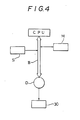
- a sensor S is embedded in the thermal print head 4 ( Figure 3) and connected via a bus B with a CPU. Also connected to the CPU via the bus B are a RAM M, in which are stored the optimum printing temperature conditions for the thermal print head 4, and a driver circuit D for the thermo-module 30.
- the direction of the driver circuit D current flow is set so that at the start of the printing the thermal print head 4 is heated.
- the sensor S detects that the temperature has reached the required level the direction of the current flow in the driver circuit D is controlled so as to cool the thermal print head 4.
- thermo-module 30 can be controlled by software or by a hard-wired logic circuit which employs an operational amplifier and other such devices.
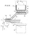
- the effect aimed at by the present invention is attained by providing the heat pipe 20 and thermo-module 30 shown in Figures 2 and 3 in the printing zone 14 which includes the thermal print head 4 and platen 5, and it is also possible to use the two in combination as is shown in Figures 5 and 6.
- Figure 5 shows a third embodiment wherein the [heat absorbing portion 20a of the] heat pipe 20 is located on the thermal print head 4 and the thermo-module 30 is arranged at the heat discharge portion 20b located away from the thermal print head 4.
- thermo-module 30 can be suitably located for the transferring of heat even with printers which are laid out in such a way that the thermo-module 30 cannot be located at the printing zone 14.
- thermo-module 30 If as indicated by the phantom line in Figure 5 the vertical arrangement of the heat pipe 20 is reversed, and the direction of current flow is reversed, the thermal print head 4 can be heated by heat from the thermo-module 30.
- thermo-module 30 is affixed to the thermal print head 4 portion and the heat pipe 20 is affixed to the thermo-module 30.
- the thermal print head 4 can be cooled directly by the thermo-module 30, providing even more effective cooling than is provided by the third embodiment.
- Figure 7 shows a fifth embodiment wherein the heat pipe 20 and the thermo-module 30 are used together and in addition it is possible to switch between heating and cooling as desired.
- removable retainers 38 are used to fasten the heat discharge portion 20b of the heat pipe 20 so the vertical orientation relative to the thermal print head 4 can be changed.
- the thermal print head 4 can be cooled, while in the arrangement indicated by the phantom lines the thermal print head 4 can be heated.
- the heat pipe 20 shown in Figures 2, 5, 6 and 7 may be of various shapes. In accordance with the requirements of the fixing position or the mode of use it may for example be flat, or long and thin, or curved, and may be of any desired size or length.
- the positioning of the heat pipe 20 is likewise not restricted to the upper part of the thermal print head 4; it may be provided anywhere that is effective in the vicinity of the thermal print head 4 and platen 5 which constitute the printing zone 14.
- the arrangement may for example be as shown in Figure 8 in which a bearing 40 is provided inside the platen 5 so the heat pipe 20 is supported rotatably relative to the platen 5, so that even when the platen 5 is rotated by a timing belt 41 the heat pipe 20 is maintained in the same position so as to be able to transfer heat from heat absorbing portion 20a to heat the discharge portion 20b.
- the heat absorbing portion 20a of the heat pipe 20 is shown incorporated integrally into the thermal print head 4 with the heat discharge portion 20b located away from the thermal print head 4.
- the numeral 50 denotes a support bracket for the heat pipe 20.
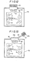
- Figures 10 to 13 show embodiments of a second aspect of the invention which enables the overall temperature of the printer to be controlled.
- Figure 10 shows the first embodiment thereof wherein an entire printer 60 is shut away from contact with the outside atmosphere in an openable housing 70, the heat absorbing portion 20a of the heat pipe 20 being provided inside the housing 70 and the heat discharge portion 20b outside.
- the heat generated by the printer 60 is discharged by being conducted at high speed from heat absorbing portion 20a of the heat pipe 20 to the heat discharge portion 20b. This allows the inside of the housing 70 to be maintained at a constant temperature.
- thermo-module 30 is provided on the end of the heat pipe 20, thereby providing the same type of active cooling as the arrangement shown in Figure 5.
- Figure 12 illustrates a third embodiment wherein the interior of the housing 70 is actively cooled by locating the cooling side of the thermo-module 30 inside the housing 70 and the heat discharge side outside.
- the heat absorbing portion 20a of the heat pipe 20 is provided on the heat discharge side of the thermo-module 30, thereby providing, similarly to the embodiment shown in Figure 6, a transfer of heat to the heat discharge portion 20b which is at high speed as well as active.
- the printer 60 may also be heated by changing the direction of the current flow in the thermo-module 30.
- thermo-module As the temperature control can be carried out with the entire printer 60 sealed off, outside dust and dirt can also be prevented from getting inside.
- a housing provide with heat transfer means such as heat pipe, thermo-module and the like is not limited to printers but may be used to house any desired device for temperature control.
Applications Claiming Priority (2)
| Application Number | Priority Date | Filing Date | Title |
|---|---|---|---|
| JP222768/85 | 1985-10-08 | ||
| JP60222768A JPH0667655B2 (ja) | 1985-10-08 | 1985-10-08 | 熱記録式プリンタ |
Publications (2)
| Publication Number | Publication Date |
|---|---|
| EP0218205A1 true EP0218205A1 (de) | 1987-04-15 |
| EP0218205B1 EP0218205B1 (de) | 1990-05-09 |
Family
ID=16787589
Family Applications (1)
| Application Number | Title | Priority Date | Filing Date |
|---|---|---|---|
| EP86113632A Expired - Lifetime EP0218205B1 (de) | 1985-10-08 | 1986-10-02 | Thermodrucker |
Country Status (5)
| Country | Link |
|---|---|
| US (1) | US4819011A (de) |
| EP (1) | EP0218205B1 (de) |
| JP (1) | JPH0667655B2 (de) |
| AU (1) | AU568254B2 (de) |
| DE (2) | DE218205T1 (de) |
Cited By (4)
| Publication number | Priority date | Publication date | Assignee | Title |
|---|---|---|---|---|
| EP0450641A2 (de) * | 1990-04-06 | 1991-10-09 | Canon Kabushiki Kaisha | Temperaturregler und Aufzeichnungsgerät |
| EP0515224A2 (de) * | 1991-05-24 | 1992-11-25 | Mitsubishi Denki Kabushiki Kaisha | Papierzuführvorrichtung für Druckgerät |
| FR2702705A1 (fr) * | 1993-01-19 | 1994-09-23 | Intermec Corp | Tête d'impression thermique. |
| US5921687A (en) * | 1991-05-24 | 1999-07-13 | Mitsubishi Denki Kabushiki Kaisha | Printing apparatus |
Families Citing this family (31)
| Publication number | Priority date | Publication date | Assignee | Title |
|---|---|---|---|---|
| JP2683126B2 (ja) * | 1988-12-28 | 1997-11-26 | キヤノン株式会社 | インクジェット記録装置 |
| US5451989A (en) * | 1989-07-28 | 1995-09-19 | Canon Kabushiki Kaisha | Ink jet recording apparatus with a heat pipe for temperature stabilization |
| US5231423A (en) * | 1989-10-20 | 1993-07-27 | Canon Kabushiki Kaisha | Ink jet recording apparatus with heat exchange means |
| GB2240514B (en) * | 1990-02-02 | 1994-04-20 | Canon Kk | Ink jet recording apparatus and ink jet recording head |
| US5272491A (en) * | 1990-10-31 | 1993-12-21 | Hewlett-Packard Company | Thermal ink jet print device having phase change cooling |
| EP0513585A3 (en) * | 1991-05-14 | 1993-05-26 | Rohm Co., Ltd. | Printing unit incorporating thermal head |
| US5211493A (en) * | 1992-06-05 | 1993-05-18 | Eastman Kodak Company | Cooling system for a thermal printing head |
| US5374944A (en) * | 1992-09-02 | 1994-12-20 | Eastman Kodak Company | Thermal printing with improved temperature control |
| US5802855A (en) * | 1994-11-21 | 1998-09-08 | Yamaguchi; Sataro | Power lead for electrically connecting a superconducting coil to a power supply |
| US6089311A (en) * | 1995-07-05 | 2000-07-18 | Borealis Technical Limited | Method and apparatus for vacuum diode heat pump |
| JPH1058726A (ja) * | 1996-06-13 | 1998-03-03 | Ricoh Co Ltd | 画像記録装置 |
| US6193349B1 (en) | 1997-06-18 | 2001-02-27 | Lexmark International, Inc. | Ink jet print cartridge having active cooling cell |
| US6044899A (en) * | 1998-04-27 | 2000-04-04 | Hewlett-Packard Company | Low EMI emissions heat sink device |
| JP3788798B2 (ja) * | 2003-10-03 | 2006-06-21 | 船井電機株式会社 | 電子機器装置および画像形成装置 |
| US6917522B1 (en) * | 2003-12-29 | 2005-07-12 | Intel Corporation | Apparatus and method for cooling integrated circuit devices |
| JP4518323B2 (ja) * | 2005-01-05 | 2010-08-04 | セイコーインスツル株式会社 | 熱活性化装置、プリンタ、熱活性化方法、および粘着ラベル製造方法 |
| ES2401437T3 (es) * | 2005-04-04 | 2013-04-19 | Roche Diagnostics Gmbh | Termociclado de un bloque que comprende múltiples muestras |
| DE102005036099A1 (de) * | 2005-08-01 | 2007-02-08 | Heidelberger Druckmaschinen Ag | Vorrichtung zur Temperierung eines Lasermodus in einen Druckplattenbelichter |
| US7825945B2 (en) * | 2006-09-18 | 2010-11-02 | Zink Imaging, Inc. | Thermal printer with auxiliary heat sink and methods for printing using same |
| WO2009111008A1 (en) | 2008-03-05 | 2009-09-11 | Sheetak, Inc. | Method and apparatus for switched thermoelectric cooling of fluids |
| CN102510990B (zh) * | 2009-07-17 | 2015-07-15 | 史泰克公司 | 热管以及热电冷却装置 |
| US8411121B2 (en) | 2011-06-14 | 2013-04-02 | Rohm Semiconductor USA, LLC | Thermal printhead with optimally shaped resistor layer |
| JP6052763B2 (ja) * | 2011-06-14 | 2016-12-27 | ローム株式会社 | サーマルプリントヘッドおよびサーマルプリンタ |
| US8305411B1 (en) | 2011-06-14 | 2012-11-06 | Rohm Semiconductor USA, LLC | Thermal printhead with temperature regulation |
| US8395646B2 (en) | 2011-06-14 | 2013-03-12 | Rohm Semiconductors USA, LLC | Thermal printer with energy save features |
| US20140111595A1 (en) | 2012-10-19 | 2014-04-24 | Zink Imaging, Inc. | Thermal printer with dual time-constant heat sink |
| US9498858B2 (en) * | 2014-08-08 | 2016-11-22 | SEAKR Engineering, Inc. | System and method for dissipating thermal energy |
| WO2016110480A1 (en) * | 2015-01-07 | 2016-07-14 | Oce-Technologies B.V. | Print head assembly |
| JP6576163B2 (ja) * | 2015-08-25 | 2019-09-18 | 大成建設株式会社 | 空調システム |
| EP4107005A4 (de) * | 2020-02-20 | 2024-03-06 | Control Print Ltd | Thermischer tintenstrahldrucker mit integrierter kühlung |
| CN115782423B (zh) * | 2023-01-30 | 2023-05-09 | 北京英特达系统技术有限公司 | 一种彩票终端打印故障检测预警方法 |
Citations (4)
| Publication number | Priority date | Publication date | Assignee | Title |
|---|---|---|---|---|
| EP0020169A1 (de) * | 1979-06-01 | 1980-12-10 | Nec Corporation | Kühlsystem für einen Zeilendrucker |
| EP0121218A1 (de) * | 1983-03-31 | 1984-10-10 | Kabushiki Kaisha Toshiba | Druckvorrichtung |
| EP0155975A1 (de) * | 1984-03-24 | 1985-10-02 | HONEYWELL BULL ITALIA S.p.A. | Vorrichtung zum Kühlen für Punktmatrixanschlagdruckkopf |
| US4552470A (en) * | 1982-11-24 | 1985-11-12 | Tokyo Shibaura Denki Kabushiki Kaisha | Thermal transfer color printer for printing on sheets of paper |
Family Cites Families (19)
| Publication number | Priority date | Publication date | Assignee | Title |
|---|---|---|---|---|
| JPS5198977A (de) * | 1975-02-26 | 1976-08-31 | ||
| US4253515A (en) * | 1978-09-29 | 1981-03-03 | United States Of America As Represented By The Secretary Of The Navy | Integrated circuit temperature gradient and moisture regulator |
| US4673030A (en) * | 1980-10-20 | 1987-06-16 | Hughes Aircraft Company | Rechargeable thermal control system |
| JPS57101040U (de) * | 1980-12-12 | 1982-06-22 | ||
| JPS57112099A (en) * | 1980-12-29 | 1982-07-12 | Fujitsu Ltd | Structure for cooling communication unit |
| US4405961A (en) * | 1981-08-06 | 1983-09-20 | International Business Machines | Thermoelectric cooling of magnetic head assemblies |
| JPS5866950U (ja) * | 1981-10-30 | 1983-05-07 | 富士写真フイルム株式会社 | インクジエツト記録装置 |
| US4402185A (en) * | 1982-01-07 | 1983-09-06 | Ncr Corporation | Thermoelectric (peltier effect) hot/cold socket for packaged I.C. microprobing |
| JPS58188676A (ja) * | 1982-04-30 | 1983-11-04 | Sato :Kk | 感熱印字装置の温度制御方式 |
| US4449033A (en) * | 1982-12-27 | 1984-05-15 | International Business Machines Corporation | Thermal print head temperature sensing and control |
| JPS59145162A (ja) * | 1983-02-08 | 1984-08-20 | Toppan Printing Co Ltd | サ−マルヘツド |
| US4620421A (en) * | 1983-05-26 | 1986-11-04 | Texaco Inc. | Temperature stabilization system |
| JPS6046706A (ja) * | 1983-08-25 | 1985-03-13 | 日新電機株式会社 | 配電盤用除湿装置 |
| JPS60116469A (ja) * | 1983-11-29 | 1985-06-22 | Matsushita Electric Ind Co Ltd | サ−マルヘツド |
| US4524343A (en) * | 1984-01-13 | 1985-06-18 | Raychem Corporation | Self-regulated actuator |
| JPS60119546U (ja) * | 1984-01-24 | 1985-08-13 | ソニー株式会社 | サ−マルヘツド装置 |
| JPS60248364A (ja) * | 1984-05-25 | 1985-12-09 | Canon Inc | サ−マルヘツド |
| JPS6112360A (ja) * | 1984-06-29 | 1986-01-20 | Ricoh Co Ltd | 熱転写記録装置 |
| US4639883A (en) * | 1984-11-28 | 1987-01-27 | Rca Corporation | Thermoelectric cooling system and method |
-
1985
- 1985-10-08 JP JP60222768A patent/JPH0667655B2/ja not_active Expired - Lifetime
-
1986
- 1986-09-30 AU AU63288/86A patent/AU568254B2/en not_active Expired
- 1986-10-02 DE DE198686113632T patent/DE218205T1/de active Pending
- 1986-10-02 DE DE8686113632T patent/DE3670983D1/de not_active Expired - Lifetime
- 1986-10-02 EP EP86113632A patent/EP0218205B1/de not_active Expired - Lifetime
- 1986-10-06 US US06/915,700 patent/US4819011A/en not_active Expired - Lifetime
Patent Citations (4)
| Publication number | Priority date | Publication date | Assignee | Title |
|---|---|---|---|---|
| EP0020169A1 (de) * | 1979-06-01 | 1980-12-10 | Nec Corporation | Kühlsystem für einen Zeilendrucker |
| US4552470A (en) * | 1982-11-24 | 1985-11-12 | Tokyo Shibaura Denki Kabushiki Kaisha | Thermal transfer color printer for printing on sheets of paper |
| EP0121218A1 (de) * | 1983-03-31 | 1984-10-10 | Kabushiki Kaisha Toshiba | Druckvorrichtung |
| EP0155975A1 (de) * | 1984-03-24 | 1985-10-02 | HONEYWELL BULL ITALIA S.p.A. | Vorrichtung zum Kühlen für Punktmatrixanschlagdruckkopf |
Cited By (9)
| Publication number | Priority date | Publication date | Assignee | Title |
|---|---|---|---|---|
| EP0450641A2 (de) * | 1990-04-06 | 1991-10-09 | Canon Kabushiki Kaisha | Temperaturregler und Aufzeichnungsgerät |
| EP0450641A3 (en) * | 1990-04-06 | 1992-08-05 | Canon Kabushiki Kaisha | Temperature regulator and recording apparatus |
| EP0663298A1 (de) * | 1990-04-06 | 1995-07-19 | Canon Kabushiki Kaisha | Temperaturregler und Aufzeichnungsgerät |
| US5486849A (en) * | 1990-04-06 | 1996-01-23 | Canon Kabushiki Kaisha | Thermal recording device with heat exchanger |
| EP0515224A2 (de) * | 1991-05-24 | 1992-11-25 | Mitsubishi Denki Kabushiki Kaisha | Papierzuführvorrichtung für Druckgerät |
| EP0515224A3 (en) * | 1991-05-24 | 1993-09-29 | Mitsubishi Denki Kabushiki Kaisha | Paper feed for printing apparatus |
| US5474394A (en) * | 1991-05-24 | 1995-12-12 | Mitsubishi Denki Kabushiki Kaisha | Printing apparatus |
| US5921687A (en) * | 1991-05-24 | 1999-07-13 | Mitsubishi Denki Kabushiki Kaisha | Printing apparatus |
| FR2702705A1 (fr) * | 1993-01-19 | 1994-09-23 | Intermec Corp | Tête d'impression thermique. |
Also Published As
| Publication number | Publication date |
|---|---|
| EP0218205B1 (de) | 1990-05-09 |
| DE218205T1 (de) | 1987-12-17 |
| JPS6283154A (ja) | 1987-04-16 |
| AU568254B2 (en) | 1987-12-17 |
| JPH0667655B2 (ja) | 1994-08-31 |
| DE3670983D1 (de) | 1990-06-13 |
| AU6328886A (en) | 1987-05-07 |
| US4819011A (en) | 1989-04-04 |
Similar Documents
| Publication | Publication Date | Title |
|---|---|---|
| EP0218205A1 (de) | Thermodrucker | |
| US5512924A (en) | Jet apparatus having an ink jet head and temperature controller for that head | |
| US4462035A (en) | Non-impact recording device | |
| WO1995016569A1 (en) | Temperature controller for ink jet printing | |
| CN211106405U (zh) | 一种医用干式胶片热敏打印机 | |
| JPH02258346A (ja) | インクジェット記録装置 | |
| JP3673698B2 (ja) | インクジェットプリンタ | |
| JP3229380B2 (ja) | 記録装置 | |
| KR101321047B1 (ko) | 닥터 블레이드의 온도 조절 장치 및 이를 이용한 건조 장치 | |
| US7724274B2 (en) | Thermal printer | |
| JP2000025253A (ja) | サーマルプリンタ | |
| JP4248041B2 (ja) | インクジェット装置 | |
| JPH03126561A (ja) | サーマルプリンタ | |
| JPS6168269A (ja) | 予熱手段を設けたサ−マルプリンタ− | |
| JPH02538A (ja) | 感熱プリンタ | |
| JPH11134453A (ja) | カードリーダライタ | |
| JPS6013650Y2 (ja) | 熱転写フイルム再生機構 | |
| JPH01139281A (ja) | 感熱記録装置 | |
| JPS63178063A (ja) | 感熱記録装置 | |
| JPH02209251A (ja) | サーマルプリンタ | |
| JPH0314689Y2 (de) | ||
| JP2003284366A (ja) | 加熱・吸熱部を有する球面アクチュエータ | |
| JP2001121759A (ja) | サーマルプリンタ | |
| JPS62246749A (ja) | 熱転写記録装置 | |
| JPS62253465A (ja) | 感熱記録装置 |
Legal Events
| Date | Code | Title | Description |
|---|---|---|---|
| PUAI | Public reference made under article 153(3) epc to a published international application that has entered the european phase |
Free format text: ORIGINAL CODE: 0009012 |
|
| AK | Designated contracting states |
Kind code of ref document: A1 Designated state(s): CH DE GB LI |
|
| 17P | Request for examination filed |
Effective date: 19870717 |
|
| DET | De: translation of patent claims | ||
| 17Q | First examination report despatched |
Effective date: 19881212 |
|
| GRAA | (expected) grant |
Free format text: ORIGINAL CODE: 0009210 |
|
| AK | Designated contracting states |
Kind code of ref document: B1 Designated state(s): CH DE GB LI |
|
| REF | Corresponds to: |
Ref document number: 3670983 Country of ref document: DE Date of ref document: 19900613 |
|
| PLBE | No opposition filed within time limit |
Free format text: ORIGINAL CODE: 0009261 |
|
| STAA | Information on the status of an ep patent application or granted ep patent |
Free format text: STATUS: NO OPPOSITION FILED WITHIN TIME LIMIT |
|
| 26N | No opposition filed | ||
| REG | Reference to a national code |
Ref country code: GB Ref legal event code: IF02 |
|
| PGFP | Annual fee paid to national office [announced via postgrant information from national office to epo] |
Ref country code: GB Payment date: 20050927 Year of fee payment: 20 |
|
| PGFP | Annual fee paid to national office [announced via postgrant information from national office to epo] |
Ref country code: CH Payment date: 20051024 Year of fee payment: 20 |
|
| PGFP | Annual fee paid to national office [announced via postgrant information from national office to epo] |
Ref country code: DE Payment date: 20051129 Year of fee payment: 20 |
|
| PG25 | Lapsed in a contracting state [announced via postgrant information from national office to epo] |
Ref country code: GB Free format text: LAPSE BECAUSE OF EXPIRATION OF PROTECTION Effective date: 20061001 |
|
| REG | Reference to a national code |
Ref country code: GB Ref legal event code: PE20 |
|
| REG | Reference to a national code |
Ref country code: CH Ref legal event code: PL |