EP0199780B1 - Apparatus for displaying a map - Google Patents
Apparatus for displaying a map Download PDFInfo
- Publication number
- EP0199780B1 EP0199780B1 EP85905470A EP85905470A EP0199780B1 EP 0199780 B1 EP0199780 B1 EP 0199780B1 EP 85905470 A EP85905470 A EP 85905470A EP 85905470 A EP85905470 A EP 85905470A EP 0199780 B1 EP0199780 B1 EP 0199780B1
- Authority
- EP
- European Patent Office
- Prior art keywords
- street
- vehicle
- map
- display
- streets
- Prior art date
- Legal status (The legal status is an assumption and is not a legal conclusion. Google has not performed a legal analysis and makes no representation as to the accuracy of the status listed.)
- Expired - Lifetime
Links
Images


Classifications
-
- G—PHYSICS
- G01—MEASURING; TESTING
- G01C—MEASURING DISTANCES, LEVELS OR BEARINGS; SURVEYING; NAVIGATION; GYROSCOPIC INSTRUMENTS; PHOTOGRAMMETRY OR VIDEOGRAMMETRY
- G01C21/00—Navigation; Navigational instruments not provided for in groups G01C1/00 - G01C19/00
- G01C21/26—Navigation; Navigational instruments not provided for in groups G01C1/00 - G01C19/00 specially adapted for navigation in a road network
- G01C21/34—Route searching; Route guidance
- G01C21/36—Input/output arrangements for on-board computers
- G01C21/3667—Display of a road map
- G01C21/3673—Labelling using text of road map data items, e.g. road names, POI names
Definitions
- the present invention relates generally to an apparatus and method for displaying a map as a navigational aid in a vehicle movable over streets and, more particularly, to a computer system and method for controlling a digital map data base used for the map display.
- Navigational aids are useful to assist the driver of a vehicle in locating his current position and for locating and moving to a desired destination.
- the navigational aid used by the driver is a conventional paper street map of a given area which is read to determine the present location of the vehicle relative to the desired location.
- Another navigational aid for the driver includes a transparency of a street map placed over a monitor which shows the approximate path of a vehicle. The map transparency is visually similar to the paper street map in that, for example, it shows the same detail of streets and landmarks and the same size of lettering of names or labels for the streets and landmarks.
- Yet another navigational aid is a video image of a map which appears on a monitor and accurately reproduces the image of a paper street map.
- the details shown in the paper map or the map transparencies may not enable the driver to grasp quickly "the lay of the land” and get a feel for his or her location and orientation with respect to the street network and/or destination. For example, the driver may not easily perceive his current position or the current heading or direction of movement of the vehicle relative to surrounding streets or landmarks.
- Yet another object of the present invention is to provide a map display whose complexity is consistent with the needs of the driver for navigational purposes.
- Still another object of the present invention is to provide a map display that always has an orientation to facilitate easy understanding by the driver and to adjust the labels so that they appear predominantly upright independent of map orientation and to label streets of interest to the driver.
- the present invention is characterised by the database further having data in the form of labels for streets, and by the apparatus further comprising:
- the driver By providing a display of a map based on a scale-dependent priority scheme, the driver will always see a map of limited complexity since only selected streets are displayed that are dependent on a selected scale level.
- the driver By providing the selective labelling, the driver will see only those labels that provide sufficient information for the current navigational need, and need not view all labels corresponding to the streets currently being displayed.
- the streets of said map database are stored as street segments each having endpoints, and said means for producing a map display showing the certain streets and the certain labels for the streets computes the slopes of the street segments from the endpoints defining the respective street segments to provide the map display.
- the driver By providing a destination symbol on the display, the driver will be able to determine easily the direction to, location of and route required to reach the desired destination. And, by providing a moving map display, the driver will view a changing map corresponding to the geographical area over which the vehicle is moving and one which is always oriented in a manner to provide ease of reading and understanding.
- the present invention will be discussed specifically in relation to a map display used in a vehicle movable over streets to provide a navigational and other informational aid for the driver or passenger.
- the vehicle that will be discussed may be a motor vehicle such as a car, a recreational vehicle (RV), a motorcycle, a bus, a truck or other such type of vehicle primarily moveable over streets.
- RV recreational vehicle
- map display features any one or more of which may be incorporated in an overall map display system in the vehicle. These features are generally identified as (1) a moving map display, (2) a scale-dependent street prioritization scheme; (3) a selective and dynamic labelling scheme, and (4) an index/destination location technique.
- Fig. 1 shows one frame of a map display M on, for example, a monitor screen MS that is used to explain generally the above-mentioned four features of the present invention. Illustrated on the monitor screen MS for a given map display M bounded by a changeable viewing window W, which is described more fully below, are a plurality of streets generally shown by reference symbol St and/or street labels, such as "ELKO” and "237". For example, "ELKO" may be a local street, while “237” may be a highway.
- the map display M shows a symbol S v representing the current location and heading of a vehicle V as the vehicle V moves over the actual streets St, a symbol S d indicating the location of a desired destination of the vehicle V and a distance-to-go (DTG) number indicating the distance between the current vehicle location and desired destination.
- a symbol S v representing the current location and heading of a vehicle V as the vehicle V moves over the actual streets St
- a symbol S d indicating the location of a desired destination of the vehicle V
- a distance-to-go (DTG) number indicating the distance between the current vehicle location and desired destination.
- the moving-map display feature is indicated schematically by the fourheaded arrow A 1 and the doubleheaded arrow A 2 .
- Arrow A 1 indicates that the map display M will move on the monitor screen MS in translation relative to the symbol S v as the vehicle V moves over the area depicted by the map display M along a street St, such as "LAWRENCE STATION".
- Arrow A 2 indicates that the map display M will rotate on the monitor screen MS about the symbol S v , and, thereby, have an orientation or heading H M as the vehicle V changes direction or heading H v .
- the symbol S v remains fixed where shown on the map display M as the vehicle V moves, with the map display M shifting in translation and/or rotation.
- the map display M is a "heading-up" map display M, in which the fixed symbol S v always is pointing upwardly.
- An arrow N is displayed in the upper right hand corner of the monitor screen MS to show the direction of true north.
- the arrow N rotates with the map display M to continually show the north direction as the vehicle V changes heading H v .
- a "north-up" map display M can be provided, in which the orientation or heading H M of the map display M is set to true north and the vehicle symbol S v is rotated to correspond to the actual vehicle heading H v .
- the scale-dependent street prioritization scheme is only indicated in Fig. 1 by the fact that the map display M is at a given scale level Z i .
- the scale level Z i can be decreased to show a larger geographical area or increased to show a smaller geographical area on the monitor screen MS.
- the complexity of the map display M will be limited by presenting only streets St of the priority appropriate for that scale level Z i .
- the feature of selective and dynamic labelling of the streets St involves a number of factors. For a given frame of a map display M, only certain of the streets St are labelled. Furthermore, the street labels are positioned on the map display M so as not to interfere with other labels and otherwise be easily readable as the map display M moves in translation and/or rotation. Moreover, the size of the labels will remain constant independent of the scale level Z i of the map M. And, each label is placed close to and parallel to its corresponding street St and with an orientation closest to right side up.
- the index/destination location feature is indicated in Fig. 1 by the destination symbol S d , and by the distance-to-go DTG from the current vehicle position represented by symbol S v to the desired destination represented by symbol S d , as shown.
- the vehicle operator or a passenger will have entered information such as an address corresponding to the desired destination, which may result in the appearance on the map display M of the symbol S d at the desired destination and a number on the map display M indicating the distance-to-go DTG in units of, for example, miles.
- a desired destination is at a location beyond the currently displayed map M for the current map display viewing window W, then the destination symbol S d will not be displayed, but the direction to the desired destination will be displayed along with the distance-to-go DTG as a navigational aid, as will be further described.
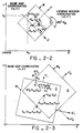
- the Map Display Viewing Window W Fig. 2-1 shows the outline of a generalized map area MA of a base map BM in a general coordinate system (X,Y) of a geographical area over which the vehicle V may move.
- the map display M presented on the monitor screen MS as the vehicle V moves can be thought of as that part or area of the base map BM that is inside a changeable viewing window W as shown, for example, in Fig. 2-1 as the box labelled W 1 or the box labelled W 2 .
- the viewing window W is defined by its four straight line boundaries.
- the viewing window W must be correspondingly rotated and translated, as described below.
- the viewing window W will grow or shrink in size accordingly and more or less base map BM will be presented on the map display M, which also will be described below.
- Symbol S V1 of Fig. 2-1 indicates the position (X V1 ,Y V1 ) and heading (H V1 ) of the vehicle V at time t 1 .
- the position (X V1 ,Y V1 ) and heading (H V1 ) are relative to the general coordinate system (X,Y).
- One viewing window W 1 shows a region of width w and height h around the vehicle V and oriented with its Y-axis along H V1 .
- the streets St (not shown) contained in the viewing window W 1 are part of the map display M on the monitor screen MS at time t 1 .
- FIG. 1 Assume now that the vehicle V moves to a new position (X V2 ,Y V2 ) and new heading (H V2 ) at a time t 2 , as indicated by symbol S V2 .
- another viewing window W 2 of the same size as window W 1 , shows a region of width w and height h around the vehicle V and oriented with its Y-axis along H V2 .
- the streets St (not shown) contained in the viewing window W 2 are part of the map display M on the monitor screen MS at time t 2 .
- Fig. 2-2 shows the general concept of a linear transformation of coordinates from the base map BM (X,Y) coordinate system to a new viewing window coordinate system (X'Y') used to define the origin and orientation of the viewing window W.
- the new axes of the viewing window W are defined by a translation of the origin of the base map BM coordinate system to a point (X o ,Y o ) and the rotation of the axes of the base map BM coordinate system by an angle (H M -90°)
- Fig 2-3 shows two vehicle positions S V1 and S V2 and two viewing windows W 1 and W 2 , respectively, with respect to the base map coordinate system (X,Y).
- the origin (X o ,Y o ) of each window W 1 and W 2 is the vehicle position (X V1 ,Y V1 ) and (X V2 ,Y V2 ), respectively
- the map headings H M are the vehicle headings H V1 and H V2 , respectively.
- a street St made up of straight line segments S 0 -S 2 defined by the XY coordinates of their end points EP, as will be described more fully below.
- the monitor screen MS remains upright and stationary in the moving vehicle V; however, the viewing window W changes as the vehicle V moves (as also illustrated in Fig. 2-1).
- the position and orientation of the street St will change within the viewing window W and hence on the monitor screen MS as the vehicle V moves, i.e., as the viewing window W translates (shifts) and rotates from W 1 to W 2 as shown in Fig. 2-3.
- This change can be computed using the linear transformation equations (1) and (2).
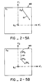
- Fig. 2-3A shows how, after the linear transformation, the street St of Fig. 2-3 will appear on the monitor screen MS with respect to the viewing window W 1 of Fig. 2-3
- Fig. 2-3B shows how the same street St will appear on the monitor screen MS with respect to the viewing window W 2 of Fig. 2-3.
- new coordinates (X' E ,Y' E ) for an end point EP of a segment S of the street St can be calculated with reference to a given viewing window W when the base map coordinates (X E ,Y E ) of the endpoints EP are known and the linear transformation parameters (X o ,Y o and H M ) of the viewing window W are known.
- the axes of a given viewing window W are defined by its origin (X o ,Y o ) which in general is the known vehicle position (X V ,Y V ), i.e., the position of S V , and its orientation H M which in general is the known vehicle heading H V -90°.
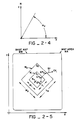
- Vehicle heading H V is defined by the angle between east (the X-axis of the base map coordinate system) and the direction of travel of the vehicle V, and is measured in a counter clockwise rotation (see Fig. 2-4).
- the subtraction of 90° in equations (1) and (2) is required because the heading-up display puts the heading H V at the vertical or 90° axis.
- the arrow N in the upper right corner of each viewing window W e.g., W 1 or W 2 of Figs. 2-3A and 2-3B, respectively
- the scale level Z i of the viewing window W defines how much of the base map BM can be seen at once on the monitor screen MS.
- Fig. 2-5 shows two viewing windows W 1 and W 2 at the same vehicle position (X V ,Y V ) represented by S V and orientation H V , but at two different scale levels Z 1 and Z 2 , respectively.
- Fig. 2-5A shows how the street St of Fig. 2-5 will appear on the screen MS in the viewing window W 1 at scale level Z 1 and Fig. 2-5B shows how the same street St will appear on the screen MS in the larger viewing window W 2 at scale level Z 2 .
- This scale adjustment is part of the linear transformation as described below.
- Equation (1) and (2) can be modified by a scale factor to adjust the map scale as given by the general linear transformation equations (3) and (4):
- X' E [(X E -X o ) cos (H M -90°)+(Y E -Y o ) sin (H M 90°)] ⁇ 2 -i
- Y' E [-(X E -X o ) sin (H M -90°)+(Y E -Y o ) cos (H M -90°)] ⁇ 2 -i
- 2 -i defines the ith power of 2 as the scale factor applied for the scale level Z i and the remaining terms are as defined in equations (1) and (2)
- the map data base is stored in the computer 12 in scale units defined here as the base map BM scale, Z o .
- the monitor screen MS has addressable locations which define its display coordinate system.
- a scale factor adjustment has to be made as shown in equations (3) and (4).
- i can be positive or negative integers, allowing the map display M to change scale by successive powers of 2.
- Other embodiments could use other fixed or variable scale factors.
- the map viewing window W is the area of the base map BM that will be seen on the monitor screen MS. It is defined by the viewing window coordinate center (X o Y o ) which is often the vehicle position (X V ,Y V ), the viewing window coordinate orientation H M which is often the vehicle heading H V , and the viewing window scale level Z i which is usually selected by the operator, as discussed more fully below. Given the addressable height and width of the monitor screen MS and the center, orientation and scale level of the viewing window W, the four straight line boundaries of the viewing window W can be defined. And the portion of the base map BM enclosed by the viewing window W can be translated, rotated and scaled according to the linear transformation equations (3) and (4) to present the map display M as on the monitor screen MS.
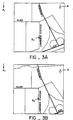
- Figs 3A-3D individually show one frame of the map display M, but in sequence show the map translation as the vehicle V moves over a given street St.
- S V the vehicle V is moving along the street St labelled as "LAWRENCE STATION” in a direction towards the street St labelled as "ELKO”.
- Figs. 3A-3D individually show one frame of the map display M, but in sequence show the map translation as the vehicle V moves over a given street St.
- the moving map display M will translate downwardly as shown by arrow A 1 with the symbol S V remaining fixed, so that another street St such as "TASMAN” comes into the map display viewing window W and is displayed on the monitor screen MS, while the street St labelled "237” moves out of the display viewing window W and hence off the monitor screen MS.
- the map display M is shifted in translation to reflect the changing positions of the vehicle V and moves as the vehicle V moves.
- Figs. 3E-3G individually show one frame of the map display M, but in sequence illustrate the rotation of the map display M as the vehicle V changes heading H V .
- the map display M will rotate in the direction shown by the arrow A 2 with the symbol S V remaining fixed.
- the map display M appears as shown in Fig. 3G.
- the map display M will translate as was described in Section IIB1 above and illustrated in Figs. 3A-3D.
- the present invention uses data identifying the heading H V of the vehicle V and data identifying the map orientation H M to accomplish this map rotation. Because the map display M can change orientation H M in correspondence with the vehicle orientation H V , the present invention may continually display true north by the arrow N shown on the map display M, as previously mentioned, to assist the driver in understanding the current heading or movement of the vehicle V.
- an alphanumeric number could appear on the monitor screen MS giving the heading H V of the vehicle V in degrees or other units. This number could be shown alone or in addition to the arrow N or other compass symbol.
- Linear Transformation In general, as previously described, the vehicle V may move in a way which changes its position (translation) and heading (rotation) individually or simultaneously.
- the viewing window W and hence the moving map display M on the monitor screen MS will change according to the linear transformation.
- the scale level Z i may be different than the base scale level Z o .
- the monitor screen MS will show a map display M of the viewing window W appropriately scaled according to equations (3) and (4).
- Figs. 3H-3J illustrate individually one frame of the map display M with the vehicle V being at a given position indicated by the symbol S V , but collectively illustrate a plurality of scale levels Z i of the map display M relative to the vehicle V being at the given position.
- Fig. 3H shows a scale level Z 2 in which the map display M shows a certain complexity of streets St. The different streets St are displayed with different intensities pursuant to their priority category described below and the scale level Z 2 .
- Fig. 3I shows a map display M at a scale level Z 3 resulting in the display of a larger geographical area surrounding the symbol S V .
- Fig. 3J shows yet another scale level Z 4 , in which an even greater geographical area surrounding the symbol S V is shown relative to the map display M of Fig. 3H (i.e., the map display viewing window W is still further enlarged).
- streets St such as "ELKO” are no longer displayed, and only more major streets St such as "CENTRAL EXPRESSWAY” and "FAIR OAKS” are displayed.
- the street "LAWRENCE STATION” on which the vehicle V is moving is not even displayed.
- the intensities of the streets St are adjusted in dependence on the street priority category and scale level Z 4 .
- the complexity of this map display M remains limited and is substantially the same as the complexity of the map displays M at scale levels Z 2 -Z 3 .
- the scale level Z i can be changed by the vehicle operator.
- Figs. 3A-3J illustrate the feature of the present invention relating to the selective and dynamic labelling scheme.
- the overall result of this selective and dynamic labelling scheme is that street labels are displayed in a manner to enable the driver to quickly and easily find the navigational information that is being sought from the map display M.
- the several selective and dynamic labelling features that provide for this result are discussed below, but not in any order of priority.
- streets St will be selected for labelling in the following priority order of categories:
- the labels are always positioned so that they are easy to read at a glance.
- the labels are always displayed along and parallel to a street St in a substantially upright orientation. This can be further explained by reference to Fig. 4 which shows various orientations A-G of the street St, and the label "ELKO" as may be displayed on monitor screen MS.
- the label “ELKO” is applied to several street segments S at different orientations, with each segment S having two endpoints EP1 and EP2.
- One endpoint is defined as the FROM node.
- the label “ELKO” is written slightly above and parallel to the segment S in the direction of the FROM node to the TO node which defines the other endpoint.
- the FROM node is generally defined as the left end point (algebraic least X value) unless the slope of the segment S (given by
- either node could be the FROM node and the determination is based upon which node was the FROM node on the last frame of the map display M.
- the labels also are positioned on the monitor screen MS so that there is a minimum interference with other labels for the other streets St, as will be described below. Labelling continues according to the above example of a priority scheme until all selected streets St are labelled or a total of, for example, five streets St are labelled, whichever comes first.
- the size of the labels remains constant irrespective of the scale level Z i of the map display M.
- the size of the labels is the same for ease of reading. In other words, the size of the labels is not disproportionately large or small as a function of the scale level Z i of the map display M.
- the driver of the vehicle V can specify a street address or select the intersection of two streets St from an index of streets St.
- the desired destination location will be shown via the symbol S d on the map display M, with the scale level Z i automatically selected to show the least area for displaying both the vehicle symbol S V and the destination symbol S d , as will be described later. If the driver subsequently changes the scale level Z i such that the desired destination location is beyond the viewing window W, the direction to that destination location is displayed by an arrow, together with the numeric distance-to-go (DTG) to that destination, as will be described below.
- TSG numeric distance-to-go
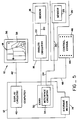
- Fig. 5 illustrates one embodiment of system hardware 10.
- the computer 12 accesses a data storage medium 14, such as a tape cassette or floppy or hard disk, which stores data including a map data base and software for processing the data in accordance with a map display algorithm, as will be described below.
- a data storage medium 14 such as a tape cassette or floppy or hard disk
- the computer 12 can be an IBM personal computer (PC) currently and widely available in the marketplace, and executes program instructions disclosed below.
- PC IBM personal computer
- Another example can be circuitry which executes the same instruction set (at the same clock rate) as the IBM PC.
- System 10 also includes means 16 for sensing the distance traveled by the vehicle V.
- the means 16 can constitute one or more wheel sensors 18 which sense the rotation of the non-driven wheels (not shown) respectively of the vehicle V and generate analog distance data over lines 20.
- Analog circuitry 22 receives and conditions the analog distance data on lines 20 in a conventional manner, and then outputs the processed data over a line 24.
- System 10 also includes means 26 for sensing the heading H V of the vehicle V.
- means 26 can constitute a conventional flux gate compass 28 which generates heading data over a line 30 for determining the vehicle heading H V .
- the computer 12 has installed in it an interface card 32 which receives the analog distance data from means 16 over line 24 and the analog heading data from means 26 over line 30.
- Interface circuitry 34 on the card 32 converts and conditions these analog data to digital data, identifying, respectively, the distance traveled by the vehicle V and heading H V of the vehicle V.
- the interface card 32 may be the commercially available Tec-Mar Lab Tender Part No. 20028, manufactured by Tec-Mar, Solon, (Cleveland) Ohio.
- Another example is custom made circuitry which performs the above-described functions.
- the system 10 also includes a display means 36, such as a CRT display or xyz monitor 38 (corresponding to monitor screen MS previously described), for displaying the map M, as well as non-map displays D such as the index of streets St, as will be further described.
- Display circuitry 40 is installed in the computer 12 and is coupled to and controls the display means 36 over lines 42, so as to display the map M, the symbol S V , the movement of the map display M relative to the symbol S V , the destination symbol S d , the street labels and the other information previously described, as well as the non-map displays D.
- the display circuitry 40 responds to data processed and provided by the card 32 in the overall computer 12 in accordance with the display algorithm of the present invention to provide the map display M and the non-map displays D.
- the display means 36 and the display circuitry 40 may be one unit sold commercially by the Hewlett-Packard Company, Palo Alto, California as model 1345A (instrumentation digital display) or may be circuitry designed especially for this function.
- the system 10 also includes an operator-controlled console means 44 having buttons 46 by which the vehicle operator may enter command and other data to the system 10, such as a desired scale level Z i , as will be further described below.
- Console means 44 communicates over a line 48 with the means 32 to input the data to the computer 12.
- the system 10 may be installed in a car.
- monitor 38 may be positioned in the interior of the car near the dashboard for viewing by the driver or front passenger. The driver will see on the monitor 38 the map display M and the other information described above.
- the console means 44 may be co-located with the monitor 38, as shown in Fig. 5A.
- the base map BM is stored on the storage medium 14 as part of the map data base which is accessed by the computer 12.
- the viewing window W is defined principally by the vehicle position (X V ,Y V ), orientation H V and scale level Z i , as previously mentioned, as well as by any PAN offsets to be described below. Once the viewing window W is defined, street segments S within the viewing window W or intersecting the straight line boundaries of the viewing window W can be retrieved from the storage medium 14 along with other related data to be used to generate the map display M.
- Data in the map data base include, as will be further described, data identifying (1) a set of line segments ⁇ S ⁇ defining the set of streets ⁇ St ⁇ , (2) street names identifying the streets St and address fields identifying numeric addresses along the streets, and (3) a code identifying each street by priority category.
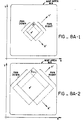
- Fig. 6A is used to explain the data stored on medium 14 that identify a set of line segments ⁇ S ⁇ defining the set of streets ⁇ St ⁇ .
- Each such street St is stored on the medium 14 as an algebraic representation of the street St.
- each street St is stored as one or more arc segments, or, more particularly, as one or more straight line segments S. As shown in Fig.
- each line segment S has two end points, for example, EP 1 , EP 2 for S 1 and EP 2 , EP 3 for S 2 , respectively, which are defined by coordinates (X 1 Y 1 ,X 2 Y 2 ) and (X 2 Y 2 ,X 3 Y 3 ) respectively, as previously mentioned, and it is these coordinate data that are stored on the medium 14 as part of the base map BM.
- These coordinate data are stored at a base map scale Z o where, for example, this scale may be such that 1 unit represents 5 feet.
- LABEL Associated with almost every street St in the map data base is its name for labeling purposes, which is shown as "LABEL" in Fig. 6A.
- a numeric address is associated with some endpoints EP defining the street address at that point. Addresses are associated to end points EP in such a way that linear interpolation can be used to approximate the location of any real address along the street St.
- Each street St has a code associated with it which identifies the priority category of the street. These categories include, for example, freeways, expressways, arterial roads, collectors, residential streets, alleys, highway access ramps and non-driveable boundaries. This code is used in connection with the scale-dependent prioritization scheme described below. Thus, for example, a 4-bit code can be used to define 16 priority categories of streets St.
- the map data base also has an alphabetical listing or index of the labels or names of streets St. Parts of this index may be called on the monitor screen MS of monitor 38 by depressing the buttons 46. One or more of these streets St may then be selected to input the desired destination data for displaying the destination symbol S d .
- Fig. 6B illustrates a portion of the index as it is displayed on the monitor 38. In addition to using two intersecting street names, one street name and a numeric address can be used to position the destination symbol S d along the street St on the map display M.
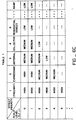
- Fig. 6C shows a lookup Table I that is stored on the storage medium 14 as part of the computer program of the present invention described below.
- the Table I shows the plurality of street priority categories versus a plurality of scale levels, e.g., levels Z 0 -Z 5 .
- For each scale level Z 0 -Z 5 there are entries corresponding to the street priority.
- the entries are indicated as "-" or “low” or “medium” or "high”. These, as will be further described, correspond to the relative brightness or intensity of the corresponding streets that are displayed or not displayed on the monitor 38 for a given scale level Z 0 -Z 10 . Where the Table I shows "-", the corresponding street St for the given scale level Z 0 -Z 10 will not be displayed.
- a residential street St will be displayed with low intensity or brightness.
- the same residential street St will not be displayed at all. Similar variations of the display intensities in dependence on the scale levels Z 0 -Z 5 can be seen by a review of the Table I.
- a street St is determined to be within the map display viewing window W of the vehicle V, then the priority category code associated with the given street St is read to determine the category of this street St. Then, a table lookup procedure is performed by the computer 12, whereby Table I is read for the current scale level Z i to determine the brightness for the given street St.
- Table I is just one embodiment of a scale-dependent priority map display M designed to limit the complexity (and maximize driver utility) of the map display M in the vehicle V.
- Figs. 7A-7C show three block diagrams which together constitute an overall computer program structure that is utilized by the system 10.
- Fig. 7A references a main program, with Figs. 7B-7C referencing interrupt programs.
- the main program of Fig. 7A computes the map display M and non-map display D for the monitor 38, as will be described in more detail below.
- the interrupt program of Fig. 7B is used to refresh the monitor 38 and to provide an operator interface via the console means 46.
- the interrupt program of Fig. 7C is a program performing a vehicle navigation algorithm, one example of which is described in detail as part of a co-pending patent application Serial No. 618,041, filed June 7, 1984, and assigned to the assignee of the present invention.
- FIG. 7C interrupts the main program of Fig. 7A about once per second and computes the current position of the vehicle V and other navigational parameters, as described in the co-pending patent application.
- the navigation program of Fig. 7C then provides the main program of Fig. 7A with input data identifying the current position (X V Y V ) for the symbol S V and the heading H V of the vehicle V. These input data are used, as will be further described, to enable the main program of Fig. 7A to compute the map display M. While a detailed understanding of the vehicle navigation program is not believed to be essential for understanding the present invention, nevertheless the above-identified co-pending application Serial No. 618,041 is, in its entirety, herein incorporated by reference.
- Data about the heading H V of the vehicle V may be obtained from the reading of the sensor 28.
- the navigation program of Fig. 7C determines that the vehicle V is on a street St, again as described in detail in the above-mentioned co-pending patent application, the identification or name of the street St and the XY coordinate data of the endpoints EP of the particular segment S (see Fig. 6A) of that street St on which the vehicle V is moving can be passed to the main program of Fig. 7A.
- the latter then may use this input data to compute a map orientation H M from the street heading H S derived from such XY coordinate data, where H S ⁇ H V , such that small changes in the sensor reading from the sensor 18 that might change H V do not change the map orientation H M .
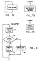
- Fig. 8 is a flow chart of the overall main program of Fig. 7A.
- the computer 12 determines the DISPLAY STATE of the system 10 (Block 8A), as will be described in Fig. 8A.
- the DISPLAY STATE represents a sequence of vehicle conditions (moving or non-moving) or operator selections via console means 44, which define the display presentation on monitor 38.
- the monitor 38 may be in one of two MAP DISPLAY STATES for displaying the map M or in a NON-MAP DISPLAY STATE for displaying alphanumeric data, such as the index of street names shown in Fig. 6B.
- the computer 12 tests the DISPLAY STATE (Block 8B) to determine if the system 10 is in a MAP DISPLAY STATE. If in a MAP DISPLAY STATE, then the computer 12 computes the map display M (Block 8C) and a return is made to Block 8A. If the system 10 is in a NON-MAP DISPLAY STATE, then the computer 12 computes the non-map display D (Block 8D), and the routine returns to Block 8A. These computations result in data which are used by the interrupt program of Fig. 7B to generate the display M or D.
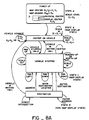
- Fig. 8A is used to explain the several DISPLAY STATES (see Block 8A of Fig. 8).
- the computer 12 causes a power-up STATE A (non-display), while computing initial map display parameters.
- the display origin is not at the physical center of the monitor 38, but, as indicated in STATE A of Fig.
- the map orientation H M defines the compass direction that is vertically up on the monitor 38 with reference to the display viewing window W and defines the orientation of the north arrow N on the monitor 38.
- the map orientation H M of a given frame of the map display M may be such that the compass direction southwest is pointing or heading up.
- the power-up STATE A is then automatically changed to a MAP DISPLAY STATE B termed a "center-on-vehicle" DISPLAY STATE B.
- the display parameters (1)-(3) and, hence, the map display M can change by motion of the vehicle V, as was illustrated in Figs. 3A-3G, and by the vehicle driver selecting a scale level Z i , as was shown in Figs. 3H-3J.
- the navigation program of Fig. 7C computes a new position (X V Y V ) which is used to define the parameters described above.
- the new heading H V of the vehicle V and which street St the vehicle V is on are combined to compute H M , where:
- the DISPLAY STATE B is automatically switched to a DISPLAY STATE C ("vehicle stopped") when the vehicle V is stopped, as may be determined, for example, from the navigation program of Fig. 7C which is calculating the distance traveled by the vehicle V.
- MAP DISPLAY STATE C in addition to the SCALE COMMANDS IN or OUT, the operator can enter commands via the buttons 46 to cause the map display M to PAN UP, PAN DOWN, PAN LEFT and PAN RIGHT.
- Each PAN command results in the computer 12 calculating a new origin (X o Y o ) of a new display viewing window W pursuant to equations 6 below and with reference to Fig. 8A-1 which shows the results of a PAN RIGHT command (dashed lines) and a PAN DOWN command (dotted lines):
- the operator can view a window W of any part of the map area MA at any scale level Z i .
- the vehicle symbol S V may no longer appear at the display center (X o Y o ); see, for example, PAN RIGHT of Fig. 8A-2.
- the computer 10 stores the coordinates (X V Y V ) of the current vehicle position.
- the display viewing window W will again be translated so that the vehicle symbol S V appears at the display center (X o Y o ) by using (X V Y V ) in equations (3) and (4) to center the viewing window W on the vehicle position (X V Y V ).
- a NORTH-UP command can be entered to select "north-up" map orientation H M , which results in the setting of the map orientation H M to true north.
- H M 90° or north and the vehicle symbol S V is rotated on the map display M corresponding to the vehicle heading H V .
- the north-up map orientation H M can be reset to the heading-up map orientation H M by entering a HEADING-UP command by which the symbol S V points up, and the map display M rotates appropriately.
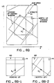
- the heading-up and north-up display viewing windows W are shown in Fig. 8B.
- the resulting map displays M are shown, respectively, in Figs. 8B-1 and 8B-2.
- the computer 12 changes between heading-up and north-up map displays M by recomputing end points EP according to equations (3) and (4) and by changing H M to H V for heading up or to 90° for north up.
- DISPLAY STATE C While in the DISPLAY STATE C, should the vehicle V move, the system 10 automatically reverts to the center-on-vehicle DISPLAY STATE B. This motion is determined if the distance between the current vehicle position X V ,Y V and the vehicle position X V ,Y V stored when STATE C was first entered, exceeds a threshold distance. Concommitantly, DISPLAY STATE C is entered if the vehicle V has not moved the threshold distance in a threshold period of time.
- DISPLAY STATE C While in DISPLAY STATE C, the operator can call a DISPLAY STATE D for entering desired destination data, as described more fully below.
- DISPLAY STATE D the operator will view on the monitor 38 and can index through by depressing appropriate buttons 46, the listing of street names of the map data base (see Fig. 6B). Once a desired destination is selected a new scale level Z i is automatically calculated. Then, the computer 12 will automatically return to DISPLAY STATE B with the current vehicle position (X V Y V ) and display heading H M to calculate the viewing window W so as to display both S d and S V , position the destination symbol S d and calculate the distance-to-go DTG data.
- Fig. 9 is a flow chart used to determine the DISPLAY STATE (see Block 8A of Fig. 8)
- the computer 12 calculates a new DISPLAY STATE (Block 9B). If the operator has not pressed a button 46 (Block 9A), but the parameters indicating motion of the vehicle V have changed (Block 9C), then the computer 12 calculates a new DISPLAY STATE (Block 9B). If such car motion parameters have not changed (Block 9C), then the computer 12 maintains the same DISPLAY STATE on the monitor 38 (Block 9D).
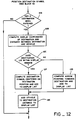
- Fig. 10 is a flow chart used to explain the computing by the computer 12 of the map display M (See Block 8C).
- the computer 12 fetches the three state parameters (Block 10A) which, as previously mentioned, uniquely define the map display viewing window W to be displayed. From these parameters, the four straight lines defining the boundary of the viewing window W are computed. Then, the position of the vehicle symbol S V is determined (Block 10B), as will be further described in Fig. 11. Next, the position of the destination symbol S d , if any, or a "direction-to-destination" DTD arrow (see Fig. 12A) is calculated along with the distance-to-go DTG data (Block 10C), as will be described in conjunction with Fig. 12.
- the map segments S within the display viewing window W are fetched from the map data base (Block 10D), as will be described more fully in relation to Fig. 14.
- the computer 12 based on the scale-dependent prioritization scheme shown in Table I, computes the intensities of the streets St (Block 10E) that lie within the map display viewing window W, as found from Block 10D.
- the computer 12 selects the labels for the streets St of the map display viewing window W (Block 10F), as will be described in relation to Figs. 16-17.
- the main program of Fig. 7A constructs a "map display file" (Block 10G) from the results of Blocks 10A-10F to be used by the refresh display program of Fig. 7B which outputs to the display hardware the map display M.
- Fig. 11 is a flow chart used to explain the computation of the position and orientation on the map display M of the vehicle symbol S V (See Block 10B).
- the map coordinates (X' V Y' V ) for the symbol S V are computed from the base map coordinates (X V ,Y V ) taken from the vehicle navigation algorithm of Fig. 7C and the linear transformation of the display viewing window W (Block 11A).
- the PAN commands can shift or translate the viewing window origin from the vehicle V, as described above.
- the current vehicle position (x' V ,y' V ), i.e., the symbol S V can be displaced from the display origin (X o ,Y o ) and, possibly, outside the viewing window W, as previously mentioned.
- the computer 12 determines if the vehicle V lies within the map display viewing window W (Block 11B) .
- Fig. 12 is a flow chart used to explain the calculation of the position of the destination symbol S d and distance-to-go DTG data (see Block 10C).
- the computer 12 determines if a destination location has been entered by the operator (Block 12A), as will be described in detail below with reference to Fig. 13 and Fig. 13A. If not, the remaining routine of Fig. 12 is bypassed.
- the computer 12 has determined the base map coordinates of the destination symbol (x d ,Y d ) , as will be explained below.
- Destination display coordinates (X' d ,Y' d ) of the destination symbol S d are determined using equations (3) and (4).
- Distance-to-go (DTG) is computed as the distance between the desired destination and the current position of the vehicle V (Block 12B), as given by equation (8).
- DTG (X V -X d ) 2 + (Y V -Y d ) 2
- the computer 12 determines if the position of the destination symbol S d lies within the map display viewing window W currently on the monitor 38 (Block 12C), the computations for which will be described below in relation to Fig. 12A. If not, the computer 12 computes a direction- to-destination arrow DTD (shown in Fig. 12A) pointing towards the desired destination and adds this to the map display file (Block 12D). Thereafter, the computer 12 adds to the map display file the distance-to-go DTG from the current position (X V ,Y V ) of the vehicle V to the desired destination (X d ,Y d ) (Block 12E). If the desired destination does lie within the map display viewing window W (Block 12C), then the computer 12 computes the position of the destination symbol S d (Block 12F) and DTG (Block 12E) and adds these data to the map display file.
- DTD shown in Fig. 12A
- Fig. 12A shows two viewing windows W i and W i+1 with two respective scale levels Z i and Z i+1 , and illustrates the calculation for determining if S d is in the viewing window W and for determining DTG. Equation (7) is used to determine if S d is in the viewing window by replacing (X' V ,Y' V ) with (X' d ,Y' d ). In this case the test will fail for viewing window W i of scale level Z i (and hence the DTD arrow is shown) and will pass for viewing window W i+1 of scale level Z i+1 .
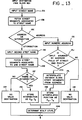
- destination data can be displayed, as will now be described in relation to the flow chart of Fig. 13 and the illustration of Fig. 13A.
- the segments S associated to that street name are fetched from the map data base (Block 13B).
- the computer 12 asks the driver to select which destination option he desires (destination by street intersection or destination by street address) (Block 13C). If the driver selects destination by street intersection by depressing a button 46, the index controls are reset and the driver may input a second street name (Block 13D). The computer 12 then fetches from the map data base the segments S associated to that name (Block 13E).
- the computer 12 then tests each segment S from the first street St against each segment S of the second street St to determine if any pair of segments S intersect (Block 13F). For example, in Fig. 13A two streets St are shown as St 1 and St 2 . St 1 has five segments S 1 -S 5 and St 2 has three segments S 1 -S 3 . According to the routine of Block 13F, the computer 12 takes the first segment S 1 of Street St 1 and the first segment S 1 of Street St 2 and determines their intersection by solving for the intersection of two straight lines. If this line intersection lies between end points of both segments, then the two segments (and hence the two streets) intersect and the search is completed. If not, S 1 of St 1 is tested against successive segments of St 2 . If still no segment intersection is found, S 2 of St 1 is tested against each segment S of St 2 and so on. In this case S 3 of St 1 and S 2 of St 2 intersect at I.
- the computer 12 stores the location of the intersection as the destination position (X d ,Y d ) (Block 13G). If no intersection is found, then no destination is computed (Block 13H) and the routine exits without specifying a destination.
- Block 13C If the driver selects the address destination option (Block 13C) by depressing a button 46, he or she then will input a numeric address (Block 13I). This address is tested against the address field data associated with the named street to see if the address number lies within (i.e., is bounded by) two address numbers associated with two segment endpoints EP (Block 13J). If it does not, then no destination is computed (Block 13K) and the routine exits without specifying one. If it is bounded, then a distance along the street St between the bounding end points EP is computed as the linear interpolation (according to street path length) of the numeric address (Block 13L). This point is stored as the destination position (X d ,Y d ) (Block 13M).
- the computer 12 computes the scale level Z i (Block 13N) to show the least area for displaying both the vehicle V centered on the monitor 38 and the destination symbol S d .
- the position of the vehicle (X V Y V ) and heading H V are used to specify the origin of the viewing window W and the orientation of its axes. This defines the display axes X' and Y'.
- the distance between S d and S V (the distance-to-go) can be broken into its orthogonal components ⁇ X' and ⁇ Y' as shown on Fig. 13B.
- the length w/2 . 2 -i defines the length from S V that can be seen in the viewing window W for the scale level Z i .
- this length is computed and compared with ⁇ X' until the first scale level is found such that this length is greater than ⁇ X' (and hence in the viewing window W).
- a height computation is compared with ⁇ Y' until a scale level is found such that the height value is greater than ⁇ Y'. The minimum of the two scale levels thus computed will determine the appropriate scale level.
- Fig. 14 is a flow chart used to explain the processing of the appropriate segments S (see Block 10D) to construct the map display M in the viewing window W.
- the computer 12 fetches the straight line boundaries of the map display viewing window W computed in Block 10A based on the parameters (1) - (3) (Block 14A).
- the computer 12 fetches a segment S of the map data base (Block 14B).
- the computer 12 then computes the XY display coordinates of each segment S and tests to see if the segment S wholly or partially lies within the viewing window W (block 14C).
- FIG. 14A A viewing window W is shown (solid box of four boundary lines) in the map area MA and the base map coordinate system X,Y. As previously indicated, there are four straight lines defining the edges of the viewing window W. Also shown in Fig. 14A are segments S 1 -S 4 . Each is defined by its endpoints EP 1 and EP 2 . Each straight line segment S 1 -S 4 is tested to determine if it intersects any of the straight lines defining the window boundary, as follows.
- segment S For a segment S, the computer 12 computes the four intersections of the segment line and the four boundary lines (segment lines parallel to boundary lines have either two or an infinite number of intersections). If the segment S intersects one or more straight lines defining the boundary of window W then the segment S falls, in part, in the viewing window W and is kept for further processing. This is the case for segment S 1 with one such intersection, and segment S 2 with two such intersections.
- Segments S 3 and S 4 do not intersect with any of the boundary lines of window W. For these cases a second test is made to see if both end points EP are on the same side of either set of parallel lines. If they are as in segment S 3 , the segment is not in the viewing window W and is discarded. If they are not as in segment S 4 , the segment is wholly within the viewing window W and is kept for further processing.
- the segments S are cropped, as described below, to match the viewing window boundary (Block 14D).
- Segments S that lie wholly inside the viewing window W are used directly in constructing the map display file.
- a new end point (EP' 1 ) is computed at the intersection and the segment S 1 is cropped or shortened to S' 1 to match the window boundary.
- two new end points (EP' 1 ,EP' 2 ) are computed and S 2 is cropped to S' 2 to match the window boundary.
- the resulting XY display coordinates of the segments S are then linearly transformed using equations (3) and (4) (Block 14E) and used to prepare the map display file, as described below.
- a segment S is either discarded (Block 14C) or transformed (Block 14E)
- a test is made to see if it was the last segment S (Block 14F). If not, another segment S is fetched (Block 14B), and the routine is repeated until all segments S are tested.
- Fig. 15 is a flow chart for explaining the computation of the display intensities of the streets St pursuant to the scale dependent prioritization scheme summarized in Table I (See Block 10E).
- the corresponding priority code is fetched from the map data base (Block 15A).
- the intensity of the corresponding street St via the look-up procedure for the current scale level Z i is determined via the Table I (Block 15B).
- This intensity is added to the display file in such a way as to instruct the display means 36 to display that given street St at the selected intensity (Block 15C).
- Block 15D a return is made to Block 15A. Otherwise, the routine is done.
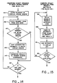
- Fig. 16 shows a flow chart for selecting the street labels (See Block 10F).
- the streets St within the map display viewing window W are placed in a certain order (Block 16A) in accordance with an ordering scheme.
- An ordering scheme will now be described in conjunction with Fig. 17.
- a street St in the viewing window W is fetched (Block 17A). That street St is tested to see if it is named (block 17B). Some streets St such as highway off-ramps are not named. If the fetched street St is not named it will not be labelled. The street St is not scored for ordering, as described below, and control is passed to fetching the next street St. If it is named (Block 17B) then the total street length within the viewing window W is computed (Block 17C) and as shown in Fig. 17A. If the fetched street St is not long enough for labelling (Block 17D), the street is not scored for ordering and control is passed to fetching the next street St.
- the fetched street St is long enough to warrant a label, it is tested to determine if this street St is the street the vehicle V is currently on (Block 17E) by, for example, comparing its name to that given by the navigation program of Fig. 7C. If it is, then the street St is given a score of 300 (Block 17F) and control is passed to fetching the next street St.
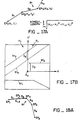
- Fig. 17B shows an example of a viewing window W, the streets St on its encompassed map display M, the vehicle symbol S V and the viewing window coordinate axes X'Y'.
- two vertical test lines TL are drawn above the X' axis and on either side of the vehicle symbol S V . If any segment S of a street St intersects either of these straight test lines TL, then it-is determined that the vehicle V will likely intersect that street St as it moves. If the street St intersects only one test line TL, the Y' coordinate of that endpoint within the test lines TL is taken to calculate a distance (i.e., D 3 of Fig. 17B). If the street St intersects both test lines TL, then the Y' coordinate of the streets' intersection with the Y' axis is taken to calculate the distance (i.e., D 4 of Fig. 17B).
- street St 1 does not intersect the vertical test lines TL.
- Street St 2 is ahead of the vehicle V but does not cross either test line TL.
- Street St 3 does intersect one test line TL and a distance D 3 will be computed.
- Street St 4 intersects twice and the distance D 4 will be computed.
- Block 17H the distance between this intersection and the vehicle V is computed (Block 17H), as shown in Fig. 17B.
- a list of these streets St and such distances is kept (Block 17I) for later processing (see Blocks 17N, 17O, 17P, 17Q). Control is then passed to fetching the next street St.
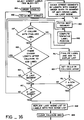
- Streets St not yet scored or disqualified are tested to determine if they are ahead of the vehicle V. This is done by testing if any end point EP is above the vehicle V, i.e., has a Y' value greater than zero for the heading-up display (Block 17J). If the street St is ahead of the vehicle V, the street St (Block 17K) is given a score of 400 plus the street priority. (A number from 1 to 16 defining street priority where 1 is the most major highway and 16 is the most minor street.) Control is then passed to fetching the next street. If it was determined that the street St is not ahead of the vehicle V, then the street St is given a score of 400 plus street priority plus 0.5 (Block 17L). Control is then passed to fetching the next street.
- Block 17M Each time control is passed to fetching the next street St, a test is made to determine if this is the last street (Block 17M). If it is not, then the next street St is fetched (Block 17A). If it is the last street St, then the list of likely intersecting streets St (from Block 17I above) is ordered by distance (Block 17N). The street St closest the vehicle V is given a score of 100 (Block 17O), the second closest street St is given a score of 200 (Block 17P) and the remaining streets St on the intersection list are scored 400 plus the street priority category (Block 17Q). And finally, the list of all scored streets is ordered by numeric score with the lowest score receiving the highest order (Block 17R). If two or more streets St have the same numeric score, the highest order is given to the street St with the longest total street length as computed in Block 17C.
- each street St is individually fetched in sequence (next highest ordered street St) (Block 16B) to determine if the fetched street can be labelled on the monitor 38.
- Each street St is comprised of one or more straight line segments S, as described above. These segments S are further reduced if two or more connecting segments S have a difference in orientations of less than a threshold (see Fig. 18A, e.g., S 1 and S 2 ).
- the resulting segments S are ordered according to their length with the longest segment S given the highest order (Block 16C). If this street St was labelled on the previous frame, the segment S which was labelled is given the highest position in the order. All segments S shorter than a threshold length are too short to label and are dropped from the list.
- the next highest ordered segment S is fetched (Block 16D).
- a tentative label position is computed (Block 16E) in the following way. First, if this segment S is labelled on the last frame the same label position relative to the endpoints EP of the segment S are used. If no label was on this segment S, a tentative position is determined by computing an offset from the FROM endpoint EP (see Fig. 4) and using the street heading H S to compute the label orientation.
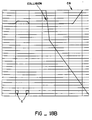
- a collision grid CG is a two-dimensional array of storage which divides the monitor 38 into cells C. At the start of the labelling routine all cells C are clear. When a label position is finalized, each cell C that contains part of the label is set (shown by shaded areas in Fig. 18B around the label "LAWRENCE”). When a tentative label position such as "TASMAN" is computed, the cells C it would occupy are tested. If any one of the cells C is set (already occupied) then a collision occurs and the tentative label position fails (Block 16F).
- the routine looks for the last possible collision cell C (Block 16G) and determines if the current segment S has sufficient length past this last collision cell C to place the label; see Fig. 18C. If the segment S cannot be labelled, a test is made to see if it is the last segment S (Block 16H). If not, the next ordered segment S is fetched (Block 16D). If it is the last segment S, that street is not labelled and a test is made to determine if that is the last ordered street St (Block 16I). If it is not the last, then the next ordered street St is fetched (Block 16B).
- Block 16L If it was the N th label (Block 16L) or the ordered list of streets has been exhausted (Block 16I), then the routine finishes by recording the locations of the finalized labels for use in ordering segments S in the next scene (Block 16M) (as described in Block 16C) and finally the collision grid CG is cleared, ready to start the process over again (Block 16N).
- the resulting map display file constructed through the various routines described above contains all the vector and intensity commands to allow the hardware vector generator card 40 to generate the map display M. Once the display file is complete, it is used by card 40 to continually refresh the monitor 38 through the software of Fig. 7B. At the same time the main program of Fig. 7A is creating a new and separate display file. Once it is complete it is used by the program of Fig. 7B to display a different frame thereby creating the changing or moving map display.
- the present invention presents a map and associated navigation information to a driver (or passenger) of a vehicle.
- This navigation aid enables the driver to extract information at a glance, thereby allowing him or her to navigate while attending to the function of driving.
- the invention allowing for this is composed of four features including a moving map display enabling the immediate vicinity of the vehicle to be displayed at an orientation which matches the vehicle's orientation, a scale-dependent street prioritization scheme which reduces the complexity of the map presentation enabling the driver to comprehend the map at a glance, a selective and dynamic labelling scheme which also simplifies extracting map information at a glance, and an index/destination location technique which enables the driver to quickly locate the position of a destination and to conveniently monitor his or her progress towards reaching that destination.
Applications Claiming Priority (3)
| Application Number | Priority Date | Filing Date | Title |
|---|---|---|---|
| US66386284A | 1984-10-22 | 1984-10-22 | |
| US663862 | 1984-10-22 | ||
| PCT/US1985/002064 WO1986002764A1 (en) | 1984-10-22 | 1985-10-17 | Apparatus and method for displaying a map |
Publications (3)
| Publication Number | Publication Date |
|---|---|
| EP0199780A1 EP0199780A1 (en) | 1986-11-05 |
| EP0199780A4 EP0199780A4 (en) | 1987-02-12 |
| EP0199780B1 true EP0199780B1 (en) | 1996-12-27 |
Family
ID=24663551
Family Applications (1)
| Application Number | Title | Priority Date | Filing Date |
|---|---|---|---|
| EP85905470A Expired - Lifetime EP0199780B1 (en) | 1984-10-22 | 1985-10-17 | Apparatus for displaying a map |
Country Status (12)
| Country | Link |
|---|---|
| EP (1) | EP0199780B1 (ja) |
| JP (9) | JPH0625909B2 (ja) |
| AT (1) | ATE146890T1 (ja) |
| AU (1) | AU5064485A (ja) |
| CA (1) | CA1248630A (ja) |
| DE (1) | DE3588138T2 (ja) |
| ES (1) | ES8900262A1 (ja) |
| IE (1) | IE76913B1 (ja) |
| MX (1) | MX171145B (ja) |
| PT (1) | PT81349B (ja) |
| WO (1) | WO1986002764A1 (ja) |
| ZA (1) | ZA858112B (ja) |
Cited By (4)
| Publication number | Priority date | Publication date | Assignee | Title |
|---|---|---|---|---|
| US7430473B2 (en) | 2004-10-01 | 2008-09-30 | Bose Corporation | Vehicle navigation display |
| DE102008021235A1 (de) * | 2008-02-25 | 2009-09-03 | Navigon Ag | Verfahren zum Betrieb eines Navigationsgeräts |
| DE102012213307A1 (de) | 2012-07-30 | 2014-01-30 | Robert Bosch Gmbh | Verfahren und Vorrichtung zum Bestimmen einer Darstellung von Beschriftungselementen einer digitalen Karte sowie Verfahren und Vorrichtung zum Anzeigen einer digitalen Karte |
| DE19941975B4 (de) * | 1999-09-03 | 2016-09-22 | Volkswagen Ag | Navigationssystem |
Families Citing this family (57)
| Publication number | Priority date | Publication date | Assignee | Title |
|---|---|---|---|---|
| CA1277043C (en) | 1985-07-25 | 1990-11-27 | Marvin S. White, Jr. | Apparatus storing a representation of topological structures and methods of building and searching the representation |
| NL8602654A (nl) * | 1986-10-23 | 1988-05-16 | Philips Nv | Werkwijze voor het in kavels verdelen en in een massageheugen bitsgewijs opslaan van een gegevensbestand, alsook voor het adresseren van een kavel, en inrichting voor het uitvoeren van de werkwijze. |
| JP2530154B2 (ja) * | 1987-04-03 | 1996-09-04 | マツダ株式会社 | 車両用ナビゲ−シヨン装置 |
| US5084822A (en) * | 1987-12-15 | 1992-01-28 | Mitsubishi Denki Kabushiki Kaisha | Navigation apparatus for moving object |
| JP2702742B2 (ja) * | 1988-07-18 | 1998-01-26 | アイシン・エィ・ダブリュ株式会社 | ナビゲーション装置 |
| JP2909626B2 (ja) * | 1988-01-01 | 1999-06-23 | 昭一 阿部 | 車輌走行表示装置 |
| DE3914589A1 (de) * | 1989-05-03 | 1990-11-08 | Bosch Gmbh Robert | Verfahren zur datenreduktion bei strassennamen |
| JP2868275B2 (ja) * | 1990-04-17 | 1999-03-10 | パイオニア株式会社 | 車載用画像情報表示装置 |
| JPH04288584A (ja) * | 1991-03-18 | 1992-10-13 | Pioneer Electron Corp | 地図表示装置 |
| WO1992021937A1 (en) * | 1991-06-05 | 1992-12-10 | Toshio Tsuyuki | Navigation apparatus and navigation method |
| JPH05119701A (ja) * | 1991-10-29 | 1993-05-18 | Clarion Co Ltd | カーナビゲーシヨン用地図表示装置 |
| DE69316898T2 (de) * | 1993-11-05 | 1998-07-30 | Philips Patentverwaltung | Fahrzeugnavigationsanzeigesystem |
| US5612881A (en) * | 1993-12-27 | 1997-03-18 | Aisin Aw Co., Ltd. | Map display system |
| EP0660290B1 (en) * | 1993-12-27 | 2000-07-12 | Nissan Motor Co., Ltd. | Apparatus and method for navigating vehicle to destination using display unit |
| US5793310A (en) * | 1994-02-04 | 1998-08-11 | Nissan Motor Co., Ltd. | Portable or vehicular navigating apparatus and method capable of displaying bird's eye view |
| DE19516647A1 (de) * | 1995-05-05 | 1996-11-07 | Bayerische Motoren Werke Ag | Navigationsvorrichtung für Kraftfahrzeuge |
| JP3393442B2 (ja) * | 1996-02-01 | 2003-04-07 | アイシン・エィ・ダブリュ株式会社 | 車両用ナビゲーション装置 |
| JP4597496B2 (ja) * | 2003-09-04 | 2010-12-15 | 三菱電機株式会社 | 表示装置 |
| ATE337643T1 (de) | 2003-09-30 | 2006-09-15 | Ericsson Telefon Ab L M | In-place entschachtelung von daten |
| JP5006187B2 (ja) * | 2004-03-23 | 2012-08-22 | グーグル インコーポレイテッド | デジタルマッピングシステムにおけるタイルの生成と供給 |
| KR100688018B1 (ko) * | 2005-02-16 | 2007-02-27 | 엘지전자 주식회사 | 도로 명 데이터의 표시위치 결정방법 |
| JP2006293553A (ja) * | 2005-04-07 | 2006-10-26 | Aisin Aw Co Ltd | フォントデータの回転処理装置及び地図表示システム |
| EP1840521A3 (en) | 2006-03-31 | 2009-02-11 | Research In Motion Limited | Methods and apparatus for associating mapping functionality and information in contact lists of mobile communication devices |
| DE602006002873D1 (de) | 2006-03-31 | 2008-11-06 | Research In Motion Ltd | Benutzerschnittstellenverfahren und Vorrichtung zur Steuerung der visuellen Anzeige von Karten mit auswählbaren Kartenelementen bei mobilen Kommunikationsvorrichtungen |
| ATE447160T1 (de) | 2006-03-31 | 2009-11-15 | Research In Motion Ltd | Verfahren und vorrichtung zur dynamischen kennzeichnung von kartenobjekten in visuell angezeigten karten mobiler kommunikationsvorrichtungen |
| US7913192B2 (en) | 2006-03-31 | 2011-03-22 | Research In Motion Limited | Methods and apparatus for retrieving and displaying map-related data for visually displayed maps of mobile communication devices |
| EP1840512B1 (en) | 2006-03-31 | 2013-03-06 | Research In Motion Limited | Method and apparatus for providing map locations in user applications using URL strings |
| ATE462956T1 (de) | 2006-03-31 | 2010-04-15 | Research In Motion Ltd | Verfahren zur kontrolle von kartenversionen und vorrichtung zur aktualisierung der verwendung von über ein netzwerk gewarteten kartendatensätzen für mobile kommunikationsvorrichtungen |
| US8121610B2 (en) | 2006-03-31 | 2012-02-21 | Research In Motion Limited | Methods and apparatus for associating mapping functionality and information in contact lists of mobile communication devices |
| KR101136684B1 (ko) | 2006-06-09 | 2012-04-23 | 도요타지도샤가부시키가이샤 | 데이터 갱신 시스템, 네비게이션 장치, 서버 장치, 및 데이터 갱신 방법 |
| JP4446201B2 (ja) | 2007-03-30 | 2010-04-07 | アイシン・エィ・ダブリュ株式会社 | 画像認識装置及び画像認識方法 |
| US8155826B2 (en) | 2007-03-30 | 2012-04-10 | Aisin Aw Co., Ltd. | Vehicle behavior learning apparatuses, methods, and programs |
| JP4501983B2 (ja) | 2007-09-28 | 2010-07-14 | アイシン・エィ・ダブリュ株式会社 | 駐車支援システム、駐車支援方法、駐車支援プログラム |
| CN101874261B (zh) * | 2007-11-27 | 2012-07-25 | 三菱电机株式会社 | 地图信息处理装置 |
| US8792916B2 (en) | 2008-01-14 | 2014-07-29 | Blackberry Limited | Dynamic prioritization of label downloads |
| US20090263026A1 (en) * | 2008-04-18 | 2009-10-22 | Google Inc. | Content item placement |
| CN103162705B (zh) * | 2011-12-16 | 2017-11-07 | 上海博泰悦臻电子设备制造有限公司 | 道路名称的显示方法和装置、导航系统 |
| US9269178B2 (en) | 2012-06-05 | 2016-02-23 | Apple Inc. | Virtual camera for 3D maps |
| US9230556B2 (en) | 2012-06-05 | 2016-01-05 | Apple Inc. | Voice instructions during navigation |
| US20130321400A1 (en) | 2012-06-05 | 2013-12-05 | Apple Inc. | 3D Map Views for 3D Maps |
| US9159153B2 (en) | 2012-06-05 | 2015-10-13 | Apple Inc. | Method, system and apparatus for providing visual feedback of a map view change |
| US9052197B2 (en) | 2012-06-05 | 2015-06-09 | Apple Inc. | Providing navigation instructions while device is in locked mode |
| US9482296B2 (en) | 2012-06-05 | 2016-11-01 | Apple Inc. | Rendering road signs during navigation |
| US9886794B2 (en) | 2012-06-05 | 2018-02-06 | Apple Inc. | Problem reporting in maps |
| US9311750B2 (en) | 2012-06-05 | 2016-04-12 | Apple Inc. | Rotation operations in a mapping application |
| US10176633B2 (en) | 2012-06-05 | 2019-01-08 | Apple Inc. | Integrated mapping and navigation application |
| US9418672B2 (en) | 2012-06-05 | 2016-08-16 | Apple Inc. | Navigation application with adaptive instruction text |
| US9997069B2 (en) | 2012-06-05 | 2018-06-12 | Apple Inc. | Context-aware voice guidance |
| US11935190B2 (en) | 2012-06-10 | 2024-03-19 | Apple Inc. | Representing traffic along a route |
| US9171464B2 (en) | 2012-06-10 | 2015-10-27 | Apple Inc. | Encoded representation of route data |
| US9418485B2 (en) | 2013-05-31 | 2016-08-16 | Apple Inc. | Adjusting heights for road path indicators |
| US9404766B2 (en) | 2013-06-08 | 2016-08-02 | Apple Inc. | Navigation peek ahead and behind in a navigation application |
| US9500494B2 (en) | 2013-06-09 | 2016-11-22 | Apple Inc. | Providing maneuver indicators on a map |
| US9273980B2 (en) | 2013-06-09 | 2016-03-01 | Apple Inc. | Direction list |
| US9530239B2 (en) | 2013-11-14 | 2016-12-27 | Microsoft Technology Licensing, Llc | Maintaining 3D labels as stable objects in 3D world |
| CN107462253B (zh) * | 2016-06-06 | 2019-01-11 | 腾讯科技(深圳)有限公司 | 一种导航数据处理方法、装置及系统 |
| JP6678609B2 (ja) | 2017-03-01 | 2020-04-08 | 株式会社東芝 | 情報処理装置、情報処理方法、情報処理プログラム、および移動体 |
Family Cites Families (29)
| Publication number | Priority date | Publication date | Assignee | Title |
|---|---|---|---|---|
| GB2115946B (en) * | 1978-12-21 | 1984-02-01 | Redifon Simulation Ltd | Improvements in or relating to visual display apparatus |
| JPS56145498A (en) * | 1980-04-14 | 1981-11-12 | Nippon Soken | Running position indicator |
| JPS5746112A (en) * | 1980-09-04 | 1982-03-16 | Honda Motor Co Ltd | Running cource indicator |
| JPS5773616A (en) * | 1980-10-25 | 1982-05-08 | Furuno Electric Co Ltd | Navigation device |
| JPS5939800B2 (ja) * | 1980-10-27 | 1984-09-26 | 本田技研工業株式会社 | 走行経路表示装置における定距離表示方式 |
| JPS57127808A (en) * | 1981-01-31 | 1982-08-09 | Jeco Co Ltd | Azimuth and traveling distance finder |
| JPS57144589A (en) * | 1981-03-04 | 1982-09-07 | Nissan Motor | Picture display unit |
| JPS6049914B2 (ja) * | 1981-03-27 | 1985-11-05 | 日産自動車株式会社 | 車両用走行誘導装置 |
| JPS6049915B2 (ja) * | 1981-04-01 | 1985-11-05 | 日産自動車株式会社 | 車両用地図表示装置 |
| JPS57169785A (en) * | 1981-04-13 | 1982-10-19 | Nissan Motor | Travelling guidance system for car |
| JPS57186111A (en) * | 1981-05-13 | 1982-11-16 | Nissan Motor Co Ltd | Map display device for vehicle |
| DE3119120A1 (de) * | 1981-05-14 | 1982-12-09 | Robert Bosch Gmbh, 7000 Stuttgart | Verfahren und vorrichtung zur orientierung eines fahrzeugfuehrers, insbesondere in einer stadt |
| JPS57201808A (en) * | 1981-06-08 | 1982-12-10 | Nippon Denso Co Ltd | Navigator to be mounted on car |
| JPS57208583A (en) * | 1981-06-18 | 1982-12-21 | Nippon Denso Co | Navigator on vehicle |
| JPS582611A (ja) * | 1981-06-27 | 1983-01-08 | Nippon Denso Co Ltd | 走行位置表示装置 |
| DE3273841D1 (en) * | 1981-07-07 | 1986-11-20 | Nippon Denso Co | Mobile navigator |
| JPS5853711A (ja) * | 1981-09-25 | 1983-03-30 | Alps Electric Co Ltd | 車載用コ−ス誘導システム |
| JPS5871408A (ja) * | 1981-10-23 | 1983-04-28 | Nippon Denso Co Ltd | 道路地図表示装置 |
| JPS58111969A (ja) * | 1981-12-25 | 1983-07-04 | 日産自動車株式会社 | 車両用走行経路表示装置 |
| JPS58122593A (ja) * | 1982-01-18 | 1983-07-21 | 日産自動車株式会社 | 図形表示装置 |
| JPS58142383A (ja) * | 1982-02-18 | 1983-08-24 | 本田技研工業株式会社 | 図形回転装置 |
| JPS58146814A (ja) * | 1982-02-24 | 1983-09-01 | Honda Motor Co Ltd | 車両用走行位置表示装置 |
| JPS58178213A (ja) * | 1982-04-14 | 1983-10-19 | Hitachi Ltd | 正立形位置表示装置 |
| JPS58193416A (ja) * | 1982-05-07 | 1983-11-11 | Honda Motor Co Ltd | 移動体の現在位置表示装置 |
| JPS58206914A (ja) * | 1982-05-27 | 1983-12-02 | Alps Electric Co Ltd | コ−ス誘導装置 |
| JPS58210512A (ja) * | 1982-06-01 | 1983-12-07 | Alps Electric Co Ltd | 走行位置表示装置 |
| US4523188A (en) * | 1982-10-25 | 1985-06-11 | The United States Of America As Represented By The Secretary Of The Army | Automated map and display alignment |
| DE3474607D1 (en) * | 1983-03-09 | 1988-11-17 | Nippon Denso Co | Map display system |
| JPS59164583A (ja) * | 1983-03-09 | 1984-09-17 | 株式会社デンソー | 地図表示装置 |
-
1985
- 1985-10-17 DE DE3588138T patent/DE3588138T2/de not_active Expired - Lifetime
- 1985-10-17 AU AU50644/85A patent/AU5064485A/en not_active Abandoned
- 1985-10-17 AT AT85905470T patent/ATE146890T1/de not_active IP Right Cessation
- 1985-10-17 JP JP60504810A patent/JPH0625909B2/ja not_active Expired - Lifetime
- 1985-10-17 WO PCT/US1985/002064 patent/WO1986002764A1/en active IP Right Grant
- 1985-10-17 EP EP85905470A patent/EP0199780B1/en not_active Expired - Lifetime
- 1985-10-21 MX MX000337A patent/MX171145B/es unknown
- 1985-10-21 PT PT81349A patent/PT81349B/pt not_active IP Right Cessation
- 1985-10-22 ES ES548848A patent/ES8900262A1/es not_active Expired
- 1985-10-22 CA CA000493521A patent/CA1248630A/en not_active Expired
- 1985-10-22 IE IE261485A patent/IE76913B1/en not_active IP Right Cessation
- 1985-10-22 ZA ZA858112A patent/ZA858112B/xx unknown
-
1997
- 1997-10-06 JP JP9287580A patent/JPH10149096A/ja active Pending
- 1997-10-06 JP JP9287579A patent/JPH10149095A/ja active Pending
- 1997-10-06 JP JP09287574A patent/JP3053377B2/ja not_active Expired - Lifetime
- 1997-10-06 JP JP9287577A patent/JP2883322B2/ja not_active Expired - Lifetime
- 1997-10-06 JP JP9287575A patent/JPH10149094A/ja active Pending
- 1997-10-06 JP JP9287578A patent/JP2813977B2/ja not_active Expired - Lifetime
- 1997-10-06 JP JP9287576A patent/JPH10143068A/ja active Pending
-
1999
- 1999-04-09 JP JP10228999A patent/JP3260722B2/ja not_active Expired - Lifetime
Cited By (5)
| Publication number | Priority date | Publication date | Assignee | Title |
|---|---|---|---|---|
| DE19941975B4 (de) * | 1999-09-03 | 2016-09-22 | Volkswagen Ag | Navigationssystem |
| US7430473B2 (en) | 2004-10-01 | 2008-09-30 | Bose Corporation | Vehicle navigation display |
| DE102008021235A1 (de) * | 2008-02-25 | 2009-09-03 | Navigon Ag | Verfahren zum Betrieb eines Navigationsgeräts |
| DE102008021235B4 (de) * | 2008-02-25 | 2010-09-16 | Navigon Ag | Verfahren zum Betrieb eines Navigationsgeräts |
| DE102012213307A1 (de) | 2012-07-30 | 2014-01-30 | Robert Bosch Gmbh | Verfahren und Vorrichtung zum Bestimmen einer Darstellung von Beschriftungselementen einer digitalen Karte sowie Verfahren und Vorrichtung zum Anzeigen einer digitalen Karte |
Also Published As
| Publication number | Publication date |
|---|---|
| IE76913B1 (en) | 1997-11-05 |
| PT81349A (en) | 1985-11-01 |
| WO1986002764A1 (en) | 1986-05-09 |
| ZA858112B (en) | 1987-06-24 |
| JPH10143068A (ja) | 1998-05-29 |
| JP2813977B2 (ja) | 1998-10-22 |
| JPH10149094A (ja) | 1998-06-02 |
| JPH10143067A (ja) | 1998-05-29 |
| JPH11325924A (ja) | 1999-11-26 |
| JPH10149096A (ja) | 1998-06-02 |
| AU5064485A (en) | 1986-05-15 |
| JPH10143069A (ja) | 1998-05-29 |
| DE3588138D1 (de) | 1997-02-06 |
| JP2883322B2 (ja) | 1999-04-19 |
| DE3588138T2 (de) | 1997-04-17 |
| ES548848A0 (es) | 1989-05-16 |
| JPS62501650A (ja) | 1987-07-02 |
| JPH0625909B2 (ja) | 1994-04-06 |
| JPH10149095A (ja) | 1998-06-02 |
| EP0199780A4 (en) | 1987-02-12 |
| IE852614L (en) | 1986-04-22 |
| PT81349B (pt) | 1987-09-18 |
| EP0199780A1 (en) | 1986-11-05 |
| MX171145B (es) | 1993-10-04 |
| JPH10260629A (ja) | 1998-09-29 |
| ES8900262A1 (es) | 1989-05-16 |
| JP3260722B2 (ja) | 2002-02-25 |
| JP3053377B2 (ja) | 2000-06-19 |
| CA1248630A (en) | 1989-01-10 |
| ATE146890T1 (de) | 1997-01-15 |
Similar Documents
| Publication | Publication Date | Title |
|---|---|---|
| EP0199780B1 (en) | Apparatus for displaying a map | |
| US4914605A (en) | Apparatus and method for displaying a map | |
| US6121900A (en) | Method of displaying maps for a car navigation unit | |
| US4675676A (en) | Map display system | |
| US4677563A (en) | Automotive navigation system | |
| US6760027B2 (en) | Bird's-eye view forming method, map display apparatus and navigation system | |
| EP0066877B1 (en) | Electronic navigator for automotive vehicles | |
| US5729109A (en) | Navigation system and intersection guidance method | |
| US6346942B1 (en) | Bird's-eye view forming method, map display apparatus and navigation system | |
| US6421604B1 (en) | Map display apparatus for motor vehicle | |
| US20030130790A1 (en) | In-vehicle navigation apparatus | |
| EP0829839A1 (en) | Land vehicle navigation system with multi-screen mode selectivity | |
| JPH07113649A (ja) | 車両用ナビゲーション方法および装置 | |
| JPH06273184A (ja) | 車両用経路誘導装置の表示方法 | |
| JPH02140788A (ja) | 地図表示方法 | |
| JP3097377B2 (ja) | 車両用経路誘導装置 | |
| JP3024464B2 (ja) | 走行位置表示装置 | |
| JPH08201092A (ja) | ナビゲーション装置 | |
| JPH04314085A (ja) | 車両用位置表示装置 | |
| JP3011991B2 (ja) | 車載ナビゲータ | |
| JPH05232868A (ja) | ナビゲーション装置 | |
| JP2779076B2 (ja) | 位置情報表示装置 | |
| JP2928374B2 (ja) | 車載ナビゲータ | |
| JP2764652B2 (ja) | 移動体の現在位置表示装置 | |
| JPH05303332A (ja) | 位置情報表示装置 |
Legal Events
| Date | Code | Title | Description |
|---|---|---|---|
| PUAI | Public reference made under article 153(3) epc to a published international application that has entered the european phase |
Free format text: ORIGINAL CODE: 0009012 |
|
| 17P | Request for examination filed |
Effective date: 19860620 |
|
| AK | Designated contracting states |
Kind code of ref document: A1 Designated state(s): AT BE CH DE FR GB IT LI LU NL SE |
|
| RAP1 | Party data changed (applicant data changed or rights of an application transferred) |
Owner name: ETAK, INC. |
|
| A4 | Supplementary search report drawn up and despatched |
Effective date: 19870212 |
|
| 17Q | First examination report despatched |
Effective date: 19900129 |
|
| RAP1 | Party data changed (applicant data changed or rights of an application transferred) |
Owner name: ETAK, INC. |
|
| APAB | Appeal dossier modified |
Free format text: ORIGINAL CODE: EPIDOS NOAPE |
|
| GRAG | Despatch of communication of intention to grant |
Free format text: ORIGINAL CODE: EPIDOS AGRA |
|
| GRAH | Despatch of communication of intention to grant a patent |
Free format text: ORIGINAL CODE: EPIDOS IGRA |
|
| APAU | Communication from the board of appeal sent |
Free format text: ORIGINAL CODE: EPIDOS OBAP |
|
| GRAH | Despatch of communication of intention to grant a patent |
Free format text: ORIGINAL CODE: EPIDOS IGRA |
|
| GRAA | (expected) grant |
Free format text: ORIGINAL CODE: 0009210 |
|
| AK | Designated contracting states |
Kind code of ref document: B1 Designated state(s): AT BE CH DE FR GB IT LI LU NL SE |
|
| REF | Corresponds to: |
Ref document number: 146890 Country of ref document: AT Date of ref document: 19970115 Kind code of ref document: T |
|
| REG | Reference to a national code |
Ref country code: CH Ref legal event code: NV Representative=s name: A. BRAUN, BRAUN, HERITIER, ESCHMANN AG PATENTANWAE |
|
| ITF | It: translation for a ep patent filed |
Owner name: DR. ING. A. RACHELI & C. |
|
| REF | Corresponds to: |
Ref document number: 3588138 Country of ref document: DE Date of ref document: 19970206 |
|
| ET | Fr: translation filed | ||
| PLBQ | Unpublished change to opponent data |
Free format text: ORIGINAL CODE: EPIDOS OPPO |
|
| PLBI | Opposition filed |
Free format text: ORIGINAL CODE: 0009260 |
|
| 26 | Opposition filed |
Opponent name: MANNESMANN AG Effective date: 19970929 |
|
| NLR1 | Nl: opposition has been filed with the epo |
Opponent name: MANNESMANN AG |
|
| PLBF | Reply of patent proprietor to notice(s) of opposition |
Free format text: ORIGINAL CODE: EPIDOS OBSO |
|
| PLBF | Reply of patent proprietor to notice(s) of opposition |
Free format text: ORIGINAL CODE: EPIDOS OBSO |
|
| PLBF | Reply of patent proprietor to notice(s) of opposition |
Free format text: ORIGINAL CODE: EPIDOS OBSO |
|
| PLBF | Reply of patent proprietor to notice(s) of opposition |
Free format text: ORIGINAL CODE: EPIDOS OBSO |
|
| PLBO | Opposition rejected |
Free format text: ORIGINAL CODE: EPIDOS REJO |
|
| APAC | Appeal dossier modified |
Free format text: ORIGINAL CODE: EPIDOS NOAPO |
|
| APAE | Appeal reference modified |
Free format text: ORIGINAL CODE: EPIDOS REFNO |
|
| APAC | Appeal dossier modified |
Free format text: ORIGINAL CODE: EPIDOS NOAPO |
|
| APAE | Appeal reference modified |
Free format text: ORIGINAL CODE: EPIDOS REFNO |
|
| REG | Reference to a national code |
Ref country code: GB Ref legal event code: 732E |
|
| REG | Reference to a national code |
Ref country code: GB Ref legal event code: IF02 |
|
| APBC | Information on closure of appeal procedure deleted |
Free format text: ORIGINAL CODE: EPIDOSDNOA9O |
|
| PGFP | Annual fee paid to national office [announced via postgrant information from national office to epo] |
Ref country code: GB Payment date: 20041008 Year of fee payment: 20 |
|
| PGFP | Annual fee paid to national office [announced via postgrant information from national office to epo] |
Ref country code: NL Payment date: 20041019 Year of fee payment: 20 Ref country code: FR Payment date: 20041019 Year of fee payment: 20 |
|
| PGFP | Annual fee paid to national office [announced via postgrant information from national office to epo] |
Ref country code: BE Payment date: 20041022 Year of fee payment: 20 Ref country code: AT Payment date: 20041022 Year of fee payment: 20 |
|
| PGFP | Annual fee paid to national office [announced via postgrant information from national office to epo] |
Ref country code: SE Payment date: 20041025 Year of fee payment: 20 Ref country code: LU Payment date: 20041025 Year of fee payment: 20 Ref country code: CH Payment date: 20041025 Year of fee payment: 20 |
|
| APBU | Appeal procedure closed |
Free format text: ORIGINAL CODE: EPIDOSNNOA9O |
|
| PLBN | Opposition rejected |
Free format text: ORIGINAL CODE: 0009273 |
|
| STAA | Information on the status of an ep patent application or granted ep patent |
Free format text: STATUS: OPPOSITION REJECTED |
|
| PGFP | Annual fee paid to national office [announced via postgrant information from national office to epo] |
Ref country code: DE Payment date: 20041222 Year of fee payment: 20 |
|
| 27O | Opposition rejected |
Effective date: 20041027 |
|
| NLR2 | Nl: decision of opposition |
Effective date: 20041027 |
|
| APAH | Appeal reference modified |
Free format text: ORIGINAL CODE: EPIDOSCREFNO |
|
| PG25 | Lapsed in a contracting state [announced via postgrant information from national office to epo] |
Ref country code: GB Free format text: LAPSE BECAUSE OF EXPIRATION OF PROTECTION Effective date: 20051016 |
|
| PG25 | Lapsed in a contracting state [announced via postgrant information from national office to epo] |
Ref country code: NL Free format text: LAPSE BECAUSE OF EXPIRATION OF PROTECTION Effective date: 20051017 |
|
| BE20 | Be: patent expired |
Owner name: *ETAK INC. Effective date: 20051017 |
|
| REG | Reference to a national code |
Ref country code: GB Ref legal event code: PE20 |
|
| REG | Reference to a national code |
Ref country code: CH Ref legal event code: PL |
|
| EUG | Se: european patent has lapsed | ||
| NLV7 | Nl: ceased due to reaching the maximum lifetime of a patent |
Effective date: 20051017 |
|
| BE20 | Be: patent expired |
Owner name: *ETAK INC. Effective date: 20051017 |