EP0147087B1 - Stickmaschine - Google Patents
Stickmaschine Download PDFInfo
- Publication number
- EP0147087B1 EP0147087B1 EP84308382A EP84308382A EP0147087B1 EP 0147087 B1 EP0147087 B1 EP 0147087B1 EP 84308382 A EP84308382 A EP 84308382A EP 84308382 A EP84308382 A EP 84308382A EP 0147087 B1 EP0147087 B1 EP 0147087B1
- Authority
- EP
- European Patent Office
- Prior art keywords
- pattern
- stitching
- embroidery machine
- machine according
- display
- Prior art date
- Legal status (The legal status is an assumption and is not a legal conclusion. Google has not performed a legal analysis and makes no representation as to the accuracy of the status listed.)
- Expired
Links
- 239000004744 fabric Substances 0.000 claims abstract description 58
- 238000000034 method Methods 0.000 claims description 85
- 230000006870 function Effects 0.000 claims description 34
- 238000009958 sewing Methods 0.000 claims description 28
- 239000011159 matrix material Substances 0.000 claims description 16
- 238000012545 processing Methods 0.000 claims description 12
- 238000013519 translation Methods 0.000 claims description 6
- 230000009467 reduction Effects 0.000 claims description 3
- 230000004044 response Effects 0.000 claims description 3
- 230000000007 visual effect Effects 0.000 claims description 3
- 238000006243 chemical reaction Methods 0.000 claims description 2
- 238000007639 printing Methods 0.000 claims description 2
- 230000009471 action Effects 0.000 abstract description 13
- 230000008569 process Effects 0.000 description 13
- 238000010586 diagram Methods 0.000 description 8
- 230000008859 change Effects 0.000 description 3
- 230000000994 depressogenic effect Effects 0.000 description 2
- 238000009956 embroidering Methods 0.000 description 2
- 238000005516 engineering process Methods 0.000 description 2
- 238000010606 normalization Methods 0.000 description 2
- 238000003672 processing method Methods 0.000 description 2
- 230000005540 biological transmission Effects 0.000 description 1
- 239000003086 colorant Substances 0.000 description 1
- 238000010276 construction Methods 0.000 description 1
- 238000012937 correction Methods 0.000 description 1
- 238000006073 displacement reaction Methods 0.000 description 1
- 230000006872 improvement Effects 0.000 description 1
- 230000004048 modification Effects 0.000 description 1
- 238000012986 modification Methods 0.000 description 1
- 238000012360 testing method Methods 0.000 description 1
Images


Classifications
-
- G—PHYSICS
- G05—CONTROLLING; REGULATING
- G05B—CONTROL OR REGULATING SYSTEMS IN GENERAL; FUNCTIONAL ELEMENTS OF SUCH SYSTEMS; MONITORING OR TESTING ARRANGEMENTS FOR SUCH SYSTEMS OR ELEMENTS
- G05B19/00—Programme-control systems
- G05B19/02—Programme-control systems electric
- G05B19/18—Numerical control [NC], i.e. automatically operating machines, in particular machine tools, e.g. in a manufacturing environment, so as to execute positioning, movement or co-ordinated operations by means of programme data in numerical form
- G05B19/4093—Numerical control [NC], i.e. automatically operating machines, in particular machine tools, e.g. in a manufacturing environment, so as to execute positioning, movement or co-ordinated operations by means of programme data in numerical form characterised by part programming, e.g. entry of geometrical information as taken from a technical drawing, combining this with machining and material information to obtain control information, named part programme, for the NC machine
- G05B19/40931—Numerical control [NC], i.e. automatically operating machines, in particular machine tools, e.g. in a manufacturing environment, so as to execute positioning, movement or co-ordinated operations by means of programme data in numerical form characterised by part programming, e.g. entry of geometrical information as taken from a technical drawing, combining this with machining and material information to obtain control information, named part programme, for the NC machine concerning programming of geometry
- G05B19/40935—Selection of predetermined shapes and defining the dimensions with parameter input
-
- D—TEXTILES; PAPER
- D05—SEWING; EMBROIDERING; TUFTING
- D05B—SEWING
- D05B19/00—Programme-controlled sewing machines
- D05B19/02—Sewing machines having electronic memory or microprocessor control unit
- D05B19/04—Sewing machines having electronic memory or microprocessor control unit characterised by memory aspects
- D05B19/08—Arrangements for inputting stitch or pattern data to memory ; Editing stitch or pattern data
-
- Y—GENERAL TAGGING OF NEW TECHNOLOGICAL DEVELOPMENTS; GENERAL TAGGING OF CROSS-SECTIONAL TECHNOLOGIES SPANNING OVER SEVERAL SECTIONS OF THE IPC; TECHNICAL SUBJECTS COVERED BY FORMER USPC CROSS-REFERENCE ART COLLECTIONS [XRACs] AND DIGESTS
- Y02—TECHNOLOGIES OR APPLICATIONS FOR MITIGATION OR ADAPTATION AGAINST CLIMATE CHANGE
- Y02P—CLIMATE CHANGE MITIGATION TECHNOLOGIES IN THE PRODUCTION OR PROCESSING OF GOODS
- Y02P90/00—Enabling technologies with a potential contribution to greenhouse gas [GHG] emissions mitigation
- Y02P90/02—Total factory control, e.g. smart factories, flexible manufacturing systems [FMS] or integrated manufacturing systems [IMS]
Definitions
- the present invention relates to an embroidery machine for stitching desired patterns on a fabric.
- Various machines such as those disclosed in US-A-4 352 334, US-A-4 413 574 and DE-A-3 243 313, have been proposed to enhance the aesthetic value of fabrics by stitching patterns on the fabrics.
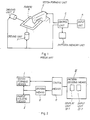
- Fig. 1 of the accompanying drawings is a schematic view showing the construction of such a known pattern forming machine. In Fig.
- A is an input unit through which the operator feeds desired patterns or the like to be formed on a fabric B
- C is a control unit which reads a control procedure previously stored in a pattern memory unit D in accordance with the input signal fed thereto from the input unit A and provides control signals in accordance with the control procedure to a stitch forming unit E and to one or more driving units F which change the relative position between the stitch forming unit E and the fabric B.
- a machine of this kind has a fixed control procedure for each elementary pattern stored in the pattern memory unit D to enable the forming of known aesthetic elementary patterns, such as capital letters and Gothic letters, by the actions of the pattern forming unit E and the driving unit F. The operator is able to select a desired elementary pattern among those stored elementary patterns and to stitch the selected elementary pattern on a fabric.
- pattern forming machines have the following disadvantages.
- the actions of the pattern forming machine responding to the input numerical codes and the resultant patterns formed on the fabric B are known only after the pattern forming machine has completed a series of actions.
- an embroidery machine comprising:
- Such a machine enables the operator to perform free pattern creation while viewing on the display unit the corresponding stitched pattern to be performed on the fabric. This facilitates quick and accurate embroidering regardless of the skill of the operator without failure owing to the previous recognition of the result of embroidering, eliminates the time taken for test stitching which has previously been necessary, and eliminates the necessity for removing stitches once formed on a fabric for correction or modification, which removal spoils the fabric.
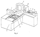
- an embroidery machine embodying the present invention comprises a stitch forming means I which forms stitches on a fabric, a fabric holding means 11 for holding the fabric, a driving means III which changes the relative position between the stitch forming means I and the fabric holding means II, a pattern deciding or determining means IV having a display unit IV-1 for two-dimensionally displaying a pattern and an input unit IV-2 for feeding a pattern to be displayed on the display unit IV-1, and a control means V which -controls the driving means III for operation on the basis of the pattern produced by the pattern deciding means IV and drives the stitch forming means I in synchronism with the actions of the driving means III.
- a known sewing machine 1 i.e., a stitch forming means, having a stitching needle 1', a shuttle (not shown) which cooperates with the stitching needle 1' and a sewing motor (not shown);
- a fabric holding unit 2 i.e., a fabric holding means, which holds a fabric by means of embroidery hoops 2' and moves on rails 3 and 4;
- a sewing table 5 on which are provided the rails 4 for guiding the movement of the fabric holding unit 2 over the sewing table 5;
- a driving unit 6 having, as shown in Fig.
- a sewing motor 6s (designated simply as “s-motor” hereinafter) for driving the stitching needle 1'
- a stepping motor 6y (designated simply as “y-motor” hereinafter) for driving the fabric holding unit 2 for movement along the rails 3
- a stepping motor 6x (designated simply as “x-motor” hereinafter) for driving the fabric holding unit 2 for movement along the rails 4
- rollers, wires and cams for converting the driving power (rotative power) of these motors into power for driving the stitching needle 1' vertically and for driving the fabric holding unit 2 linearly along the rails
- a keyboard 7 of a microprocessor 9 i.e., an input unit, through which input control information of a created pattern is given
- a cathode-ray tube 8 (abbreviated to "CRT” hereinafter), i.e.
- a two-dimensional display unit for enabling the operator to recognize visually a pattern which is nearly the same as a pattern created by operating the keyboard 7 and to be actually formed on the fabric, when the pattern is created, modified or corrected in accordance with the input information given by means of the keyboard 7; the microprocessor 9 which functions as a control means and a pattern deciding means which provide control signals for controlling the three motors 6s, 6x, 6y of the driving unit 6 to form a pattern which is nearly the same as the pattern displayed on the CRT 8 by operating the keyboard 7 on a fabric; a magnetic disk memory 20; and a printer 21.
- Fig. 4 is a block diagram showing the functional relation between the components of the embodiment shown in Fig. 3.
- the keyboard 7 functioning as an input unit
- the CRT 8 functioning as a display unit.
- the driving unit 6 is provided, as explained with reference to Fig. 3, with three motors 6x, 6y and 6s.
- a central processing unit 10 (abbreviated to "CPU” hereinafter) for controlling the entire control system
- ROM read-only memory
- RAM random access memory
- a pattern ROM 13 stores previously a plurality of patterns which are to be selected by input signals given by means of the keyboard 7.
- the pattern ROM 13 includes a basic ROM 13a which functions as a first memory unit and stores geometric pattern elements formed by straight lines and curves, and character pattern ROMs 13b which function as a second memory unit and store alphabetical characters of block letter, Gothic letter and capital letter type.
- a chip select 14 is provided to expand the memory area and the character pattern ROM 13b has a plurality of ROM chips.
- a keyboard interface 15 is provided to enable the transmission of information between the CPU 10 and the keyboard 7.
- a CRT controller 16 controls the CRT 8 in accordance with the instruction given by the CPU 10 to make the CRT 8 display the contents written in a video RAM 17 in accordance with the instruction given by the CPU 10.
- An x-y motor controller 18 controls the x-motor 6x and the y-motor 6y for rotation in the normal direction or the reverse in accordance with an instruction given by the CPU 10 so that the fabric holding unit 2 is moved appropriately.
- a sewing motor controller 19 controls the sewing motor 6s likewise in accordance with an instruction given by the CPU 10 to drive the stitching -needle 1' for vertical movement.
- a DMA controller 22 transfers the data stored in a magnetic disk memory 20 at a high speed to the RAM 12.
- Fig. 5 is a schematic perspective view of the keyboard 7 functioning as an input unit.
- function keys 7a for deciding the mode of keyboard input data
- selection keys 7b such as well-known alphabetical character keys for various selection
- ten keys 7c for facilitating the execution of numeral input operation
- operation keys 7d marked with arrows symbolizing the operation of the system and provided from the view point of practical facility of the system
- light emission diodes 7e (abbreviated to "LED” hereinafter) for visually indicating input admittance for the operation keys 7d to improve the accessibility.
- LED light emission diodes 7e
- These keys constitute a first input unit and a second input unit.
- Indicated at 7f is a connector to transmit information to the microprocessor.
- Fig. 6 shows an example of display on the CRT 8.
- the screen of the CRT 8 is divided into two areas, namely, into a function display area 8a in the left side of the screen for displaying the functions of system and pattern display area 8b in the right side of the screen for visually displaying created patterns.
- a cursor 8c is provided to improve the accessibility of the system by indicating a function indication corresponding to a function selected by means of the function keys 7a of the keyboard 7.
- the pattern display area 8a has a dot matrix of a predetermined dot density.
- a created pattern is displayed by the luminescense of the dots among the dot matrix calculated through a series of procedures for visual recognition of the created pattern.
- Fig. 7 shows the memory system of the character pattern ROM 13b storing pattern elements.
- the memory system for an alphabetic character "A" is shown by way of example.
- each pattern element is stored in a set of a plurality of points with respect to a point CO corresponding to a first reference point defined for each pattern element.
- the reference point CO is located at the middle of the height H and at the middle of the width W of the pattern element, namely, at the center of the pattern element.
- Stitching points 1 S, 2S, 3S, ..., and 12S are defined with respect to the reference point CO and a set of a plurality of columns (closed areas I, II and III in Fig. 7) define a pattern element of a width.
- Such a pattern element defined by a set of columns is stitched actually by controlling the operation of the sewing machine 1 and the driving unit 6 in the following procedure.
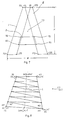
- columns are classified generally, from the nature of pattern elements, into two kinds of columns, namely, columns as shown in Fig. 8 formed by straight lines interconnecting stitching points and columns as shown in Fig. 9 formed by curves interconnecting stitching points. Accordingly, the present system is able to stitch pattern elements surely and correctly even if those two kinds of columns are moved in any manner.
- the column shown in Fig. 8 is defined by stitching points 1S, 2S, 3S and 4S represented by Cartesian coordinates ( X1 , Y 1 ) ' (X 2 , Y 2 ) (x 3 , Y 3 ) and ( X4 , y 4 ) respectively with respect to the reference point CO as the origin. It is understood that this column can be stitched as shown in Fig. 8 by calculating stitching point shifting distances x 1 , Y 1 , X2 and y 2 .
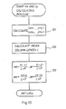
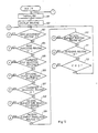
- Fig. 10 shows a flow chart of a procedure for calculating the stitchinq point shifting distances ⁇ x 1 , ⁇ y 1 , Ax 2 and ⁇ y 2 . This proce- .
- Step 101 is executed to obtain the respective middle points of sides between (x i , y 1 ) and ( X2 , y 2 ) and between ( X3 , y 3 ) and (x 4 , y 4 ) which are necessary for calculating the mean length L of the column.
- the mean column length L is calculated by using the result (xm 1 , ym 1 ) and (xm 2 , ym 2 ) of Step 101.
- the objective stitching point shifting distances ⁇ x 1 , ⁇ y 1 , ⁇ x 2 and ⁇ y 2 are calculated on the basis of a predetermined stitching pitch P (stitches/cm) and the mean column length L.
- P stitches/cm
- a control procedure for stitching the curved column shown in Fig. 9 will be described hereinafter in connection with the flow chart of Fig. 11. Differing from the rectangular column showing in Fig. 8, the column of this kind is defined as shown in Fig. 9 by five points: (x 1 , y,), (x 2 , y 2 ), (x 3 , Y 3 ), (X 4 , y 4 ) and (X 2 , y 5 ).
- Step 201 of the flow chart of Fig. 11 is executed.
- Step 201 the respective middle points (xm 3 , ym 3 ) and (xm 4 , ym 4 ) of lines extending between the points (x 1 , y,) and (x 2 , y 2 ) and between the points (x 3 , y 3 ) and (x 4 , Y 4 ) are calculated.
- Step 202 the equation of a circle passing those two middle points and the stitching point (x 3 , y 3 ) is formed and the center (xc, yc) and the radius r of the circle is calculated.
- Step 203 the following two values are calculated on the basis of the circle with the center at (xc, yc) and the radius r and the middle points (xm 3 , ym 3 ) and (xm 4 , ym 4 ). Firstly, an angle a between a straight line segment extending between the points (xc, yc) and (xm 3 , ym 3 ) and secondly a length L of an arc of the circle with the radius r on the angle are calculated.
- Step 204 the angle Aan for an arc formed on the circle with the center at (xc, yc) and with a radius r by each stitch in stitching an arc of the length La at a predetermined pitch is calculated by the use of the values of a and La obtained at Step 203.
- Step 207 the differences ⁇ rn between the actual stitching points (xon, yon), (xin, yin) and the imaginary stitching points (xon, yon), (xin, yin) and the imaginary stitching points (xdn, ydn) are calculated.
- Step 208 (xon, yon) is calculated with respect to the known origin (xdn, ydn) on the basis of ⁇ rn, ⁇ an and an.
- the pattern element storing system of the character pattern ROM 13b i.e., the second memory means of this system, and the process for calculating the stitching points at which the stitching needle 1' forms stitches on a fabric on the basis of stored information have been described in detail.
- the pattern element is displayed visually on the CRT 8 through the same procedures.
- a dot matrix formed of a set of a plurality of regularly arranged dots is provided previously in the pattern display unit of the CRT 8 and the dots corresponding to the stitching points shown in Figs. 8 to 11 are caused to emit light for the visual display of the pattern elements so that a pattern which is practically the same as a pattern to be formed on a fabric under the control of the microcomputer 9 is displayed two-dimensionally on the CRT 8.
- This embodiment is constituted so that a pattern which is practically the same as a pattern to be actually stitched by the stitching needle 1' is displayed through the calculation of straight lines passing the stitching points determined in accordance with the above-mentioned procedure.
- Fig. 12 is a flow chart of the main control routine of the control system according to the present invention.
- Step 301 is an initialization routine for clearing and initializing the controllers of the system, namely, the RAM 12, the video RAM 17, the CRT controller 16, the x-y motor controller 18 and the sewing motor controller 19, which are used for necessary control operations.
- Step 302 is a display routine in which the main processing procedure is started and the ready state of control operations for the following operations is displayed on the CRT 8. The contents of the display on the CRT 8 are those as shown in the function display area 8a in Fig. 6.
- Steps 303 to 312 various function routines are selected upon the input of instructions. That is, when the function keys f1 to f9 are not operated, Steps 301 to 312 are carried out sequentially and the process is returned again to Step 303 to repeat the closed loop. If either of the function keys f1 to f9 is operated, a routine among routines to 19 corresponding to the step corresponding to the operated function key is performed, and then the process is returned to a routine 11 to perform the process of the closed loop of Steps 303 to 312.
- the selection of a routine among the selectable routines 2 to 19 is indicated as mentioned earlier on the function display area 8a by indicating a letter representation corresponding to the function by operating the function keys 7a of the keyboard 7 with the cursor 8c as shown in Fig. 6 so that the operating status of the system can always be recognized.
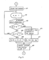
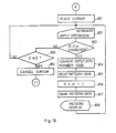
- Fig. 13 is a flow chart of a zero adjust routine selected at Step 303 of Fig. 12.
- the zero adjust routine defines the relative position between a pattern formed on the CRT 8 and the stitching needle 1'.
- Step 402 the decision of either automatic or manual operation for "Zero adjustment” is asked by displaying "A or M?" on the CRT 8 to demand for the input of "A" (Automatic) or "M” (Manual).
- Step 403 the procedure waits for keyboard input and when any key is operated, the procedure advances to Step 404.
- Step 404 decision is made whether or not the input character at Step 403 is "A”. If “A”, the procedure goes to Step 405 and if not "A” the procedure goes to Step 406. At Step 406, decision is made if the input character at the preceding Step 403 is "M" or not. If not "M” the procedure returns to Step 402 to demand for the input either of "A” or of "M".
- Step 405 The routine of Step 405 is implemented when the input is "A" to command the x-motor and the y-motor of the driving unit 6 to move the embroidery hoops 2' unconditionally to the predetermined corner of the sewing table 5, which facilitates mounting a fabric on the embroidery hoops 2'.
- data Nx and Ny are stored as variables Xx and Yx which are necessary to move the embroidery hoops 2' which have previously been moved to the predetermined corner of the sewing table 5 to a position exactly below the stitching needle 1' of the sewing machine 1 when the function "Stitch" is implemented.
- the routine of Step 409 is implemented when (Xs, Ys) are set at Step 407 or 408.
- the indication by the cursor and the representation "A" or "M?" provided at Steps 401 and 402 are cancelled to indicate the completion of the routine of Step 409.
- the procedure returns to the main routine 11 of Fig. 12 as shown in Fig. 13.
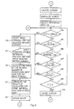
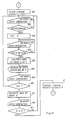
- Fig. 14 is a flow chart of a "Base display” routine selected at Step 304 of Fig. 12.
- This routine is represented by a display "Base” displayed on the CRT 8.
- This "Base display” routine displays basic geometric patterns in the pattern display area 8a to facilitate the creation of a pattern consisting of a set of pattern elements.
- the cursor is located at the head of the representation "Base” on the CRT 8 to indicate that the "Base display” routine has been selected by operating the function key f2.
- Step 502 is a normalization step to set the control system for the processing of numeric inputs on a Cartesian coordinate system with its origin at the center of the pattern display area 8b of the CRT 8.
- the pattern display area 8b of the CRT 8 is provided with a matrix of m lines and n rows which displays a pattern by dots of light emitted by the elements of the matrix. Since assigning the elements of the matrix is a troublesome task, the Cartesian coordinate system with its origin at the center of the pattern display area 8b, i.e., point 0 shown in Fig. 15, is employed for the successive operations.
- the control system normalized at the normalization step causes an element of the matrix represented by a point (no+6, mo-3) on the matrix to emit light.
- the basic ROM 13a storing formulas of basic patterns for forming various geometric patterns is selected by using the chip select 14 and connected to the system including the CPU 10 to enable the implementation of the successive routines on the basis of the data stored in the basic ROM 13a.
- the closed loop of Steps 504 to 509 includes processes for the selection of the formulas of the basic patterns stored in the basic ROM 13a.
- five kinds of formulas namely, formulas for circle, ellipse, straight line, involute and cycloid, are stored in the basic ROM 13a.
- the pattern specified by the operator is calculated on the basis of the basic formula and the necessary data which have been obtained at steps by Step 511 and the calculated result is normalized at Step 513.
- the normalized result is stored in the video RAM 17 as information representing the elements of the matrix.
- the CRT controller 16 makes, on the basis of the data stored in the video RAM 17, the corresponding elements of the matrix formed in the CRT 8 emit light.
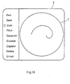
- the pattern selecting and displaying routine is recurrently executable, two or more pattern elements can be displayed on the CRT 8 as shown in Fig. 16.
- the size of the embroidery hoops 2 is shown typically by a circle C, and then an involute is displayed inside the circle C, which enables the creation of a pattern within the range defined by the embroidery hoops 2'.
- Step 509 After a desired geometric pattern has thus been displayed on the CRT 8, an "END" key is depressed to execute Step 509. Then, the procedure leaves the selection Steps 504 through 509 and goes to the successive Step 515. At Step 515, the cursor displayed at Step 501 is cancelled and the procedure returns to the main routine 11 of Fig. 12.
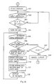
- Fig. 17 is a flow chart of a "Style selection" routine which is executed when selected at Step 305 of Fig. 12.
- Step 602 decision is made whether or not the input information given by operating the keyboard 7 at Step 602 is either one of numerals 1, 2, 3 and 4 and when the input information is other than those numerals, Step 602 is repeated and the same procedure is repeated.
- Step 607 is executed.
- the character pattern ROM 13b consisting of a plurality of ROMs is selected and one of the ROMs is connected electrically to the control system including the CPU 10 to execute control operation by using the data stored in the selected ROM.
- This embodiment employs a chip select 14 for selecting a ROM 13 among a plurality of the ROMs 13, however, the selection may be made likewise through the application of a software.
- the character pattern ROM 13b employed in this embodiment consists of four ROMs to improve the flexibility of the system by constructing part of the character pattern ROM 13b in the cartridge system so that a set of character styles can be stored--in a single cartridge.
- Step 608 the cursor displayed at Step 601 is cancelled to indicate the completion of this. routine. Then, the procedure returns to the main routine 11 of Fig. 12.
- Fig. 18 is a flow chart of a "Pitch setting" routine. This routine is selected at Step 306 of Fig. 12 and is executed by operating the function key f4 of the keyboard 7.
- Step 701 the same actions performed in the above-mentioned routines are performed. The description of those actions are omitted.
- Step 702 keyboard input operation is waited for. When any input operation is performed, the procedure goes to Step 703.
- Step 703 it is decided whether or not the input given at Step 702 is an numeric input within a predetermined range of pitch (stitches/cm). If the input is a numeral within the predetermined range, Step 704 is executed and if not, it is decided that a wrong operation has been made and the procedure is returned to Step 702 to wait for a new input.
- an input numeric data given at Step 702 is set for the variable P when decision is made that the input numeric data is normal.
- Step 705 is identical with that of Step 608, hence the explanation thereof will be omitted.
- Fig. 19 is the same as the above-mentioned Steps 401, 501, 60.1 and 701, hence the explanation thereof will be omitted.
- Step 802 keyboard input operation is waited for and the execution of the routine is suspended until some input is given.
- Step 803 is an input information discriminating step, in which decision is made if the input is one given by means of the selection keys 7b or not. If the input is an input given by means of the selection key 7b, the routine goes to Step 804.
- Step 804 the input given by means of the selection keys 7b is converted into an "Address code" in accordance with a predetermined conversion code system.
- Address codes represent storage locations corresponding to a single character (Fig. 7) stored in each character pattern ROM 13b.
- the character pattern ROM 13b is one ROM selected through the execution of the style selection routine of Fig. 17.
- a desired pattern element is selected through the execution of Step 804.
- the CPU 10 reads the data representing one selected pattern element, namely, the desired data among those stored in the character pattern ROM 13b and stores the same data in a predetermined storage area in the ROM 12.
- Step 806 the variable N is subjected to an incremental operation.
- the variable N is initialized to "0" in the initializing routine of the main routine of Fig. 12.
- the pattern data stored in the predetermined storage area at Step 805 is subjected to ranking using the variable N to enable the designation of the selected pattern data for the control system in -the following processes only by designating the rank.
- the selected pattern element is displayed on the CRT 8.
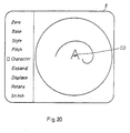
- the pattern data stored in the RAM 12 at Step 805 is calculated to determine the stitching points of the pattern element according to the procedure explained in connection with Figures 8-11, and then the data of the determined stitching points is normalized with respect to the center of the pattern display area 8b as the origin of the x-axis and the y-axis of a Cartesian coordinate system and the normalized data is given to the video RAM 17. For example, if a character "A" is selected when the screen of the CRT 8 is in the state as shown in Fig. 16, the character "A" is displayed on the screen as shown in Fig. 20. As apparent from Fig.
- the center of each pattern element is stored as the center CO of the corresponding pattern data and the pattern data is normalized with the center of the pattern display area 8b of the CRT 8 as the origin of the Cartesian coordinate system at Step 808 of this routine, therefore, the pattern element is displayed in the central position on the screen of the CRT 8 as shown in Fig. 20.
- Step 808 After the operation at Step 808 has been completed, the procedure returns to Step 802. If it is desired to select a plurality of characters, selection of characters by means of the selection keys 7b and the successive execution of the above-mentioned routine including Steps 802 to 808 is repeated.
- Step 809 decides if the key "End" was operated at Step 802. If so, the procedure goes to Step 810 and if not, it is decided that an erroneous operation was made and the procedure is returned again to Step 802.
- Step 810 the procedure is returned to the main routine 11.
- Fig. 21 is a flow chart of the "Character size" routine to be selected at Step 308 shown in Fig. 12.
- Step 901 the selecting of this routine is indicated, similarly to the indication at Steps 401, 501, ... and 801, by the cursor placed at the head of the representation "Expand" on the CRT 8.
- Step 902 waits forthe operation of the keyboard for designating the size of the pattern element.
- the procedure goes to Step 903 when a value corresponding to a desired expansion or reduction within a predetermined range of a pattern element (Fig. 7) is provided by means of the ten keys 7c of the keyboard 7.
- Step 903 the numeric data given at Step 902 is examined to decide if the numeric data is within the predetermined range. If not, the procedure is returned to Step 901 to require the reexecution of the numeric data input operation. If the input numeric data is within the predetermined range, the procedure goes to Step 904.
- the input numeric data is stored in the form of a variable K.
- a pattern element magnifying factor has been decided by executing Steps 901 to 904
- a pattern element to be magnified or reduced by the magnifying factor "K" is given by operating the keyboard 7 at Step 905.
- Step 906 decision that the input numeric data is equal to or less than the variable N is made. If the input numeric data is greater than the variable N, the procedure is returned to Step 905 to require the reexecution of the input operation. If the numeric data is equal to or below the variable N, the procedure goes to Step 907.
- Step 907 data representing the coordinates of a stitching point stored in the pattern storage area with the rank N in the RAM 12 is read, the x-distance and y-distance of the coordinates are multiplied by value K of the variable K and there resultant values are stored temporarily in another area in the RAM 12.
- the pattern data of rank N stored in the RAM 12 is expanded or reduced with the refrence point CO of pattern data by the magnifying factor K.
- the pattern data of rank N expanded or reduced by the magnifying factor K is displayed on the CRT 8. Since this routine only magnifies the data of the stitching point by the magnifying factor K, the pattern data is displayed on the CRT 8 with the first reference point CO of the pattern data of rank N as the center. Accordingly, the character A is displayed as shown in Fig. 20 and when the character A is doubled in size, the character A is expanded around the reference point CO as shown in Fig. 22.
- Step 909 the expanded pattern element displayed on the CRT 8 is examined visually to decide if the expanded pattern element is approvable and an input representing the decision is given.
- Step 910 the input representing the decision is examined. If the input indicates that the expanded pattern element is not approvable, the procedure is returned to Step 902 and the above-mentioned procedure is repeated until a desired pattern is obtained. If the input indicated that the expanded pattern element is approvable, the procedure goes to Step 911.
- Step 911 the data is rewritten.
- the data multiplied by the magnifying factor K and stored at Step 907 is stored again at the data address of each stitching point stored in the pattern storage area of the rank N in the RAM 1?.
- the data mulitplied by the magnifying factor K and stored temporarily is erased, since the data is necessary no longer, for the effective utilization of the storage capacity of the RAM 12.
- Step 912 an input representing the necessity of the expansion or reduction of a further pattern element through this routine or the end of this routine is given.
- the input given at Step 912 is examined at Step 913 to decide if a further pattern element needs to be processed through this routine. If any pattern element needs to be processed through this routine, the procedure goes to Step 902 so that the preceding steps are repeated. If not, Step 914 is executed to cancel the indication by the cursor established at Step 901 to inform the operator of the end of this routine and the procedure is returned to the main routine 11.
- Fig. 23 shows a flow chart of "Character displacement” routine, which is selected by step 309 of the main routine. This routine carries out the translation of pattern elements as designated by "Displace" on the CRT 8.
- Step 1001 the cursor is placed at the head of the indication "Displace" on the CRT 8 to indicate that the control system is prepared for the execution of this routine.
- Step 1002 the rank N attached to a pattern element desired to be moved through the execution of this routine is given.
- Step 1003 decision if the input given at Step 1002 is correct. when a number greater than the rank N presently set in the control system is given or no numeric input is given, the procedure is returned to Step 1002 to require correct input operation. When a correct input is given, the procedure goes to Step 1004.
- Step 1004 among the pattern data of the rank N stored in the RAM 12, the data of the reference point CO of the stitching points of the pattern element is loaded.
- the data of the point CO of each pattern element is the coordinates (xco, yco) on the imaginary Cartesian coordinate system on the CRT 8. Accordingly, the data of the point CO which has just been displayed on the CRT 8 through the execution of the character selection routine shown in Fig. 18 is (0, 0), hence the pattern element is displayed with its center at the zero point of the pattern display area 8b as shown in Fig. 20 or 22.
- Step 1005 the LED 7e is turned on to indicate readiness for the input operation of the operation keys 7d of the keyboard 7.
- This routine is capable only of the translation of pattern elements, the LED provided at the center of the arrangement of arrows indicating upward, downward, rightward and leftward directions respectively and the operation of the keys provided with those arrows indicating those four directions respectively is effective thereafter.
- Step 1006 input operation is waited for and when any input operation is performed, the next Step 1007 is executed.
- Step 1007 the input given at Step 1006 is examined to decide if the input is one that was given by operating either one of those four operation keys, i.e., the keys with arrows.
- the procedure goes to Step 1008. Otherwise, the procedure goes to Step 1013.
- the key input is examined to decide if it is an input given by means of the END key. If the key input is an input other than the input by means of the END key, the key input is identified as a false input and the procedure goes to Step 1002. When an input by means of the END key, the procedure goes to Step 1014.
- Step 1014 the cursor displayed at Step 1001 is cancelled and the LED turned on at Step 1005 is turned off to indicate the completion of the execution of this routine and the procedure is returned to the main routine @ .
- Step 1008 is executed when an input is given by means of the key with arrow to clear the contents of the video RAM 17 corresponding to the rank N of the pattern element provided at Step 1003. That is, since the CRT controller 16 controls the CRT 8 on the basis of the contents of the video RAM 17 to display a picture on the CRT 8, the pattern of the pattern rank N is erased from the CRT 8.
- Step 1009 is executed to update the value of the reference point CO of the pattern element in accordance with the input of the key with arrow through a simple add-subtract operation, namely, when the input is given by the key with the arrow "-" for the translation of the reference point CO in the negative direction of the x-axis of the coordinate system shown in Fig.
- Step 1010 two operations are performed. First, the new coordinates of the point CO is stored in the RAM 12. Secondly, all the stitching points are calculated in accordance with the computing procedure described with reference to Figs. 8 to 11.
- the computed data is normalized appropriately for display on the CRT 8 and the normalized data is stored in the video RAM 17.
- Step 1012 the CRT controller 16 is controlled on the basis of the normalized data stored in the video RAM 17 to display the pattern element on the CRT 8 at a location translated by Ex or Ey from the original location, and then the procedure is returned to Step 1006.
- Steps 1006 through 1012 are executed repeatedly and the pattern element can be translated by the constant Ex or Ey every time the Steps 1006 through 1012 are executed as long as the keys with arrow are operated.
- a pattern element is translated stepwise for a fixed distance at a time, however, the final coordinates (xco, yco) of the pattern element may-be designated directly, in which the point CO is set directly at Step 1009 of thus routine.
- the coordiantes of each stitching point is calculated individually in this embodiment for the effective utilization of the memory area, however, it is also possible to achieve the translation of the pattern element, depending on the capacity of the CPU and the capacity of the storage area, by storing the data normalized at Step 1011 in another storage area and by adding a constant to or subtracting a constant from all the data.
- This processing method enhances the processing speed, however, an appropriate processing method may be selected taking the ability of the system into account, since the enhancement of the processing speed requires an increased storage area.
- Fig. 24 shows a flow chart of a "Character rotation" routine which is selected at Step 310 of the main routine.
- Step 1101 the cursor is placed at the head of indication "Rotate" provided on the CRT 8 representing this routine in an abbreviated form to indicate the readiness of the control system for the execution of this routine.
- Step 1102 keyboard input operation is waited for and when any keyboard input is given, the procedure goes to Step 1103.
- Step 1103 the keyboard input is examined to decide if the keyboard input is an input indicating the rank N attached to the pattern element shown in Fig. 19. If not, the procedure is returned to Step 1102 requiring the repetition of the operation of Step 1102. If so, the next Step 1104 is executed to turn on the LED 7e shown in Fig. 5. In this case, since only the operation keys for pattern rotation are designated, only the LED indicating a pair of keys with arrow on the upper right-hand corner of Fig. 5 is turned on.
- Step 1105 keyboard input is waited for and when the operation key or some key is operated, the procedure goes to Step 1106.
- Step 1106 the keyboard input is examined to decide if the keyboard input is given by means of the operation key, i.e., the key with arrow. If so, the procedure goes to Step 1109 and if not, to Step 1107.
- Step 1107 decision if this routine is to be ended is made.
- Step 1108 is executed to cancel the cursor indicated at Step 1101 and to turn off the LED turned on at Step 1104. Then, the procedure goes to the main routine 11. If the keyboard input was made by means of a key other than the END key, the keyboard input is decided to be a false input and the procedure is returned to Step 1102.
- Step 1109 is executed when an input is given by means of the operation key as mentioned earlier to erase the pattern of rank N which was given at Step 1102 from the CRT 8. That is, the data obtained by normalizing the pattern data of rank N stored in the RAM 12 and stored in the video RAM 17 is cleared.
- the data of stitching points among the pattern data attached with rank N and stored in the RAM 12 is updated on the basis of the reference point CO in accordance with the operation either of the operation key with the arrow " " or of the operation key with the arrow " ⁇ ''.
- the coordinates (xs, ys) of each stitching point are updated to coordinate (xs', ys') by turning the coordinates (xs1, ys) in a counterclockwise direction through an angle 8 about the point CO as shown in Fig.
- This angle ⁇ is a predetermined constant of the control system.
- the updated pattern data of the rank N is normalized for display on the CRT 8 and the normalized updated pattern data is stored in the video RAM 17.
- the CRT controller 16 makes the CRT 8 display the data stored in the video RAM 17.
- the Steps 1104 to 1112 are executed successively. Therefore, the pattern element can be turned successively stepwise by the angle 8 at a time when the key with the arrow " " or " " is kept depressed.
- the data stored in the RAM 12 is updated at each turning of the pattern element.
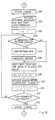
- Fig. 26 shows a flow chart of a "Stitching" routine selected at Step 311 of the main routine. This routine is executed to form a pattern consisting of pattern elements created previously on the display area 8b on a fabric.
- Step 1201 the cursor is placed at the head of an indication "Stitch" on the CRT 8 to indicate the readiness of the control system for the execution of this routine.
- the sequence of pattern elements to be stitched on the fabric by the sewing machine 1 is given when a plurality of pattern elements (the rank N is greater than one) are to be stitched through the execution of this routine, information if it is necessary to stitch points having no connection with the pattern to be stitched (designated as "idle points" hereinafter) by the stitching action of the stitching needle 1' between the completion of stitching one pattern element and the start of stitching the next pattern element and, when it is necessary to stitch idle points, the coordinates (xa, ya) of each idle point (coordinates on the imaginary Cartesian coordinate system on the CRT 8 as shown in Fig. 15) and the timing of stitching each idle point are given as input information to the control system.
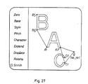
- stitching is performed from the starting point Bfto the last point B1 of the letter B, then from the starting point Af to the last point A1 of the letter A, and then from the starting point Cf to the last point C1 of the letter C.
- the stitching needle 1' is shifted to the starting point Af of the letter A after the completion of the stitching of the letter B, the stiching yarn carried by the stitching needle 1' extends between the last point B1 of the letter B and the starting point Af of the letter A.
- the stitching yarn extends between the last point A1 of the letter A and the starting point Cf of the letter C.
- the yarn extending between the letters the yarn extending between the points B1 and Af has nothing at all to do with stitching those three letters, whereas the yarn extending between the points A1 and Cf is buried beneath the yarn forming the letter C when the letter C is stitched and the removal of the yarn buried beneath the stitching is practically impossible. Therefore, the pattern element stitching sequence needs to be changed or the stitching operation of the sewing machine needs to be interrupted after the completion of the stitching of every pattern element to remove the yarn extending between the last point of the preceding pattern element and the starting point of the succeeding pattern element.
- idle points are provided to obviate the above-mentioned inconvenience.
- an idle point Q is provided. After completing the stitching of the letter A, the sewing machine 1 stitches the point Q, and then starts stitching the letter C.
- a stitching sequence of the letter B, the letter A, the point Q and the letter B, the letter A, the point Q and the letter C and the coordinates (xa, ya) of the point Q are fed into the control system at Step 1202.
- initialization is performed to set the sequence (variable I) at 1 (one).
- Step 1204 decision that the first stitching object is a pattern element or an idle point is made. If the first stitching object is an idle point, the procedure jumps to Steps 1205 and 1206 and goes to Step 1207. If it is a pattern element, the procedure goes to Step 1205.
- Step 1205 the RAM 12 storing the pattern element designated by the sequence I and the stitching points and the coordinates of the reference point CO of the pattern element is read.
- the pattern element is divided into columns on the basis of the data read at Step 1205 and all the stitching points are calculated as explained in connection with Figs. 8 to 11.
- Step 1207 zero adjustment is performed by controlling the x-motor 6x and the y-motor 6y of the driving unit to bring the reference point of the embroidery on the fabric into coincidence with the needle 1'.
- First power is supplied to the driving unit 6 in accordance with the zero data (Xs, Ys) which was described in connection with Fig. 12.
- This embodiment is capable of establishing two zero adjustment modes, namely, manual zero adjustment mode and automatic zero adjustment mode. In the manual zero adjustment mode, no power is supplied to the x-motor 6x and y-motor 6y, since the zero data (Xs, Ys) is (0, 0).
- the embroidery hoops 2' are moved automatically to a position right below the stitching needle 1' since the zero data (Xs, Ys) is (Nx, Ny) (data for controlling the x-motor 6x and the y-motor 6y so that the center of the embroidery hoops 2' located on a corner of the sewing table 5 is shifted to a position right below the stitching needle 1').
- the data of the presently executed sequence I is the data of a pattern element
- the x-motor 6x and the y-motor 6y are driven on the basis of the coordinates (xco, yco) of the reference point CO of the data of the pattern element and when the data of the presently executed sequence I is the data of an idle point, the x-motor 6x and the y-motor 6y are driven on the basis of the coordinates (xa, ya) of the idle point to decide the position of the fabric relative to the stitching needle 1', and then the procedure goes to Step 1208.
- initialization is performed to change the zero point from (Xs, Ys) to (0, 0).
- initialization is performed to perform stitching operation with the zero point of the same data as that of sequence 1.
- stitches are formed actually on the fabric. If the data of sequence I is the data of a pattern element, the x-motor 6x and the y-motor 6y are controlled on the basis of the data of all the stitching points calculated at Step 1206 and if the data of sequence I is the data of an idle point, the x-motor 6x and the y-motor 6y are controlled on the basis of the coordinates of the idle point, to move the fabric holding unit 2. Then a command is given to control the sewing motor 6s for stitching the stitching points or a stitching point by vertically reciprocating the stitching needle 1'.
- Step 1210 an increment is given to the stitching sequence I, that is, an increment of 1 is given to the present stitching sequence I (a variable). Then, the procedure goes to Step 1211.
- Step 1211 it is decided whether or not the sequence I has been executed for all the pattern data and the number of the idle points by using an inequality: I>N+(number of idle points). If the inequality is true, the procedure goes to Step 1212, where the cursor provided at Step 1201 is cancelled to indicate the end of this routine and the procedure is returned to the main routine 11. If the inequality is not true, the procedure is returned to Step 1204 of this routine to repeat the same control actions.
- a well-known light pen as an input device in addition to the keyboard 7 as shown in Fig: 28 for the further functional improvement of the system.
- a light pen When a light pen is provided, the coordinates (xa, ya) of a necessary idle point and the stitching points immediately before and immediately after the idle point (stitching points A1 and Cf in Fig. 27) are indicated with the light pen so that the system is able to decide after which pattern element and before which pattern element the idle point is to be stitched.
- the use of a light pen also enables the highly free creation of patterns.
- the use of a special push-button input device 90 as shown in Fig. 29 will improve the efficiency of data input operation.
- a two-dimensional pattern to be displayed on the CRT 8 is produced by combining aesthetic pattern elements which have previously been prepared and the location on the CRT, the size and the angular position of those pattern elements can freely and selectively be changed. Accordingly, a desired creative pattern can readily be displayed visually on the CRT 8.
- the pattern displayed on the CRT 8 is processed properly by the microprocessor 9 and the sewing machine 1 and the driving unit 6 are controlled in accordance with the output control signals given by the microprocessor 9 so that practically the same pattern as shown on the CRT 8 is formed automatically on a fabric.
- the created pattern can simply be fed into the control system without requiring complicated procedure such as coding and the pattern to be formed actually on the fabric after the completion of a series of actions of the control system can be recognized beforehand on the CRT 8.
- the two-dimensional display of a pattern imaged by the operator on the CRT 8 enables the recognition of the imaged pattern on the same dimension as the dimension of the actual pattern, therefore, time and skill for recognizing the imaged pattern are -unnecessary, hence any person, either skilled or not skilled, is able to create patterns simply and to form the created pattern on a fabric.
- the present invention is applicable also to an embroidery machine equipped with multiple sewing heads and capable of forming each pattern element by yarns of various colors.
- the data (Xs, Ys) for zero adjustment shown in Fig. 13 is set for each sewing head and the zero point of each sewing head is moved to the origin of the Cartesian coordinate system on the CRT 8. Therefore the zero point of each sewing head need not be changed at all as all the pattern data is defined with respect to the origin of the Cartesian coordinate system.
- additional functions to display a pattern element stored in the character pattern ROM 13b on the CRT 8 in association with a geometric pattern displayed on the CRT 8 by processing the geometric pattern data stored in the reference ROM 13a at a tilted position corresponding to the curvature of the geometric pattern by calculating the curvature and the relevant tangent to the geometric pattern at a specific point thereon, such as to display the pattern element on the calculated tangent by defining the angle of rotation of the pattern element, and providing the subroutines of the main routine shown in Fig. 12 with editing function are readily achievable through the utilization of well-known computer graphic technology. Even in the application of the present invention in combination with such well-known computer graphic technology, the present embodiment is not subject to any change and is capable of correctly forming practically the same pattern as that displayed on the CRT 8 on a fabric.
- the magnetic disk memory 20, included in the control system according to the present embodiment is capable of storing patterns displayed on the CRT 8. Accordingly, patterns can simply be corrected on the basis of the patterns stored in the magnetic disk memory 20.
- the printer 21 also included in the control system according to the present embodiment is capable of printing patterns before stitching the same and the copies of the printed patterns can be used as means of information.
Landscapes
- Engineering & Computer Science (AREA)
- Physics & Mathematics (AREA)
- Human Computer Interaction (AREA)
- Textile Engineering (AREA)
- Microelectronics & Electronic Packaging (AREA)
- Geometry (AREA)
- Computer Hardware Design (AREA)
- Manufacturing & Machinery (AREA)
- General Physics & Mathematics (AREA)
- Automation & Control Theory (AREA)
- Sewing Machines And Sewing (AREA)
- Bakery Products And Manufacturing Methods Therefor (AREA)
- Manufacturing And Processing Devices For Dough (AREA)
- Automatic Embroidering For Embroidered Or Tufted Products (AREA)
Claims (21)
dadurch gekennzeichnet,
Priority Applications (1)
| Application Number | Priority Date | Filing Date | Title |
|---|---|---|---|
| AT84308382T ATE36733T1 (de) | 1983-12-01 | 1984-12-03 | Stickmaschine. |
Applications Claiming Priority (2)
| Application Number | Priority Date | Filing Date | Title |
|---|---|---|---|
| JP58227139A JPS60119981A (ja) | 1983-12-01 | 1983-12-01 | 刺繍ミシン |
| JP227139/83 | 1983-12-01 |
Publications (2)
| Publication Number | Publication Date |
|---|---|
| EP0147087A1 EP0147087A1 (de) | 1985-07-03 |
| EP0147087B1 true EP0147087B1 (de) | 1988-08-24 |
Family
ID=16856091
Family Applications (1)
| Application Number | Title | Priority Date | Filing Date |
|---|---|---|---|
| EP84308382A Expired EP0147087B1 (de) | 1983-12-01 | 1984-12-03 | Stickmaschine |
Country Status (5)
| Country | Link |
|---|---|
| US (1) | US4622907A (de) |
| EP (1) | EP0147087B1 (de) |
| JP (1) | JPS60119981A (de) |
| AT (1) | ATE36733T1 (de) |
| DE (1) | DE3473621D1 (de) |
Families Citing this family (65)
| Publication number | Priority date | Publication date | Assignee | Title |
|---|---|---|---|---|
| JPH0657279B2 (ja) * | 1985-04-19 | 1994-08-03 | ウィルコム プラプライテリ リミテッド | ステッチプロセッサ |
| JPH0671504B2 (ja) * | 1985-08-30 | 1994-09-14 | ブラザー工業株式会社 | 文字及び模様等を縫製可能なミシン |
| JPS6253694A (ja) * | 1985-09-03 | 1987-03-09 | ブラザー工業株式会社 | 円形の縫製エリアを設定可能なミシン |
| JPS6253695A (ja) * | 1985-09-03 | 1987-03-09 | ブラザー工業株式会社 | 矩形の縫製エリアを設定可能なミシン |
| JPS6282994A (ja) * | 1985-10-04 | 1987-04-16 | ジューキ株式会社 | 刺繍機の制御装置 |
| US4742786A (en) * | 1985-11-20 | 1988-05-10 | Brother Kogyo Kabushiki Kaisha | Data processing system for sewing machine |
| US4781130A (en) * | 1986-09-12 | 1988-11-01 | Barudan America, Inc. | System for stitching along a curve |
| JPS63122496A (ja) * | 1986-11-13 | 1988-05-26 | ブラザー工業株式会社 | ミシンのためのデ−タ作成装置 |
| JPS63139586A (ja) * | 1986-12-01 | 1988-06-11 | ブラザー工業株式会社 | 刺繍ミシンのための針位置データ処理装置 |
| GB2199165B (en) * | 1986-11-21 | 1991-01-09 | Brother Ind Ltd | Stitch data processing apparatus for embroidery sewing machine |
| JP2808276B2 (ja) * | 1987-01-16 | 1998-10-08 | 蛇の目ミシン工業株式会社 | 刺しゆう縫ミシンのデータ入力装置 |
| JPH0667420B2 (ja) * | 1987-02-14 | 1994-08-31 | ブラザー工業株式会社 | 自動ミシン |
| US4735159A (en) * | 1987-02-17 | 1988-04-05 | Titan-Baratto | Embroidery machine |
| JPS63267387A (ja) * | 1987-04-24 | 1988-11-04 | ブラザー工業株式会社 | ミシン |
| JP2595970B2 (ja) * | 1987-05-19 | 1997-04-02 | ブラザー工業株式会社 | 表示装置を有するミシン |
| IT1217954B (it) * | 1987-06-29 | 1990-03-30 | Tokai Ind Sewing Machine | Macchina per ricamare |
| JP2597496B2 (ja) * | 1988-02-17 | 1997-04-09 | 東海工業ミシン株式会社 | 自動刺繍機 |
| FR2624890B1 (fr) * | 1987-07-14 | 1991-05-24 | Tokai Ind Sewing Machine | Machine a broder |
| DE3823562C2 (de) * | 1987-07-14 | 1996-11-28 | Tokai Ind Sewing Machine | Stick- oder Nähmaschine |
| US5001996A (en) * | 1987-07-22 | 1991-03-26 | Tokai Kogyo Mishin Kabushiki Kaisha | Embroidering machine |
| SE459103B (sv) * | 1987-10-05 | 1989-06-05 | Husqvarna Ab | Symaskin med grafiska instruktioner |
| JP2596028B2 (ja) * | 1987-12-15 | 1997-04-02 | ブラザー工業株式会社 | 自動ミシンのためのデータ作成装置 |
| US4815406A (en) * | 1988-01-11 | 1989-03-28 | Ssmc Inc. | Compound stitch pattern for a sewing machine |
| JP2649540B2 (ja) * | 1988-04-28 | 1997-09-03 | 蛇の目ミシン工業株式会社 | 刺しゅうミシン |
| JPH01287707A (ja) * | 1988-05-16 | 1989-11-20 | Mitsubishi Electric Corp | 数値制御装置の加工データの作成方法 |
| JPH0693945B2 (ja) * | 1988-09-22 | 1994-11-24 | ブラザー工業株式会社 | ミシンのためのデータ作成装置 |
| US4953485A (en) * | 1989-04-10 | 1990-09-04 | Td Quilting Machinery | Automatic quilting machine for specialized quilting of patterns which can be created by utilizing computer graphics in conjunction with a reprogrammable computer |
| CH679407A5 (de) * | 1989-07-11 | 1992-02-14 | Mefina Sa | |
| US5074232A (en) * | 1989-07-27 | 1991-12-24 | Brother Kogyo Kabushiki Kaisha | Pattern sewing machine |
| DE3929948A1 (de) * | 1989-09-08 | 1991-03-21 | Pfaff Haushaltmasch | Naehmaschine mit einer elektronischen steuereinrichtung |
| DE4027364A1 (de) * | 1990-08-30 | 1992-03-05 | Pfaff Haushaltmasch | Verfahren und naehmaschine zur herstellung von naehmustern |
| JPH0738906B2 (ja) * | 1990-10-25 | 1995-05-01 | ブラザー工業株式会社 | ミシンの刺繍データ作成装置 |
| US5261340A (en) * | 1991-02-19 | 1993-11-16 | Mim Industries, Inc. | Detachable template clamp having a removable sewing template |
| US5427043A (en) * | 1991-03-28 | 1995-06-27 | Mim Industries, Inc. | Workpiece pallet having a detachable workpiece holder and method of sewing a workpiece |
| JP2624005B2 (ja) * | 1991-03-29 | 1997-06-25 | 三菱電機株式会社 | ミシンの縫製データ作成装置 |
| US5146859A (en) * | 1991-06-20 | 1992-09-15 | Mim Industries, Inc. | Adjustable clamp for use in a sewing machine |
| US5666895A (en) * | 1991-06-20 | 1997-09-16 | Mim Industries, Inc. | Adjustable clamp |
| US5445090A (en) * | 1991-07-25 | 1995-08-29 | Mim Industries, Inc. | Interchangeable clamp for use in a sewing machine |
| JP2921185B2 (ja) * | 1991-08-08 | 1999-07-19 | ブラザー工業株式会社 | ミシンのための模様データ処理装置 |
| US5163376A (en) * | 1991-09-06 | 1992-11-17 | Mim Industries, Inc. | Tubular seaming system |
| JP2867770B2 (ja) * | 1991-11-05 | 1999-03-10 | ブラザー工業株式会社 | 刺繍ミシン用ステッチデータ作成方法 |
| JPH0731765A (ja) * | 1993-07-26 | 1995-02-03 | Brother Ind Ltd | ミシン |
| JPH0956942A (ja) * | 1995-06-15 | 1997-03-04 | Brother Ind Ltd | 縫製データ処理装置 |
| EP0753614B1 (de) * | 1995-07-14 | 2000-05-10 | Fritz Gegauf Ag Bernina-Nähmaschinenfabrik | Verfahren zur Gestaltung des Programmspeichers einer elektronischen Nähmaschine, Nähmaschine zur Durchführung dieses Verfahrens und Anwendung der Nähmaschine |
| JP4052686B2 (ja) * | 1995-12-05 | 2008-02-27 | 蛇の目ミシン工業株式会社 | 外殻模様縫い機能を有する刺繍縫いミシン及びデータの生成装置 |
| US5896295A (en) * | 1996-09-10 | 1999-04-20 | Brother Kogyo Kabushiki Kaisha | Embroidering apparatus and method |
| JPH10146490A (ja) * | 1996-11-20 | 1998-06-02 | Brother Ind Ltd | シール印刷機能付きミシン |
| JPH11226275A (ja) * | 1998-02-12 | 1999-08-24 | Brother Ind Ltd | パッチワーク編集装置及びパッチワーク編集装置を動作させるためのプログラムを格納した記録媒体 |
| JP2001000761A (ja) * | 1999-06-21 | 2001-01-09 | Brother Ind Ltd | 刺繍縫製可能なミシンの表示装置 |
| SE520388C2 (sv) * | 2002-03-28 | 2003-07-01 | Vsm Group Ab | Broderielement, metod för att brodera ett mönster samt metod för att designa ett mönster |
| GB2387854B (en) | 2002-04-22 | 2005-12-07 | Viking Sewing Machines Ab | Providing character data for use by an embroidery machine |
| JP4153859B2 (ja) * | 2003-10-15 | 2008-09-24 | 株式会社島精機製作所 | 刺繍データ作成装置と刺繍データの作成方法及び刺繍データの作成プログラム |
| JP2007082812A (ja) * | 2005-09-22 | 2007-04-05 | Juki Corp | ミシン |
| SE529489C2 (sv) * | 2006-11-28 | 2007-08-21 | Vsm Group Ab | Symaskin med stor stygnbredd |
| US20110168070A1 (en) * | 2007-08-30 | 2011-07-14 | Pierre Lanquist | Sewing machine modification tools |
| CN101809216B (zh) * | 2007-08-30 | 2015-10-21 | Vsm集团股份公司 | 针脚数据对象的定位 |
| WO2009061258A1 (en) * | 2007-11-09 | 2009-05-14 | Vsm Group Ab | Thread cut with variable thread consumption in a sewing machine |
| WO2009085005A1 (en) * | 2007-12-27 | 2009-07-09 | Vsm Group Ab | Sewing machine having a camera for forming images of a sewing area |
| CN102277696B (zh) | 2010-06-09 | 2015-03-11 | Vsm集团股份公司 | 送料器移动补偿 |
| JP2012179088A (ja) * | 2011-02-28 | 2012-09-20 | Happy Kogyo Kk | 電子ミシン |
| US8960112B2 (en) | 2013-02-01 | 2015-02-24 | Vsm Group Ab | Stitching system and method for stitch stop embellishments |
| US9010259B2 (en) * | 2013-08-06 | 2015-04-21 | Abm International, Inc. | Quilted pattern input digitizing frame |
| JP6494953B2 (ja) * | 2014-08-21 | 2019-04-03 | 蛇の目ミシン工業株式会社 | 刺繍ミシンの刺繍縫い変換装置、刺繍ミシンの刺繍縫い変換方法、刺繍ミシンの刺繍縫い変換プログラム |
| JP6815887B2 (ja) * | 2017-02-15 | 2021-01-20 | 蛇の目ミシン工業株式会社 | ミシン |
| CN113388971B (zh) * | 2021-06-19 | 2022-05-10 | 汝州玛雅机电科技有限公司 | 多花样顺序刺绣控制系统及其方法 |
Family Cites Families (14)
| Publication number | Priority date | Publication date | Assignee | Title |
|---|---|---|---|---|
| AU530956B2 (en) * | 1979-10-25 | 1983-08-04 | Janome Sewing Machine Co. Ltd. | Pattern selecting system of electronic sewing machine |
| DE2938294C2 (de) * | 1978-09-22 | 1985-03-14 | Janome Sewing Machine Co., Ltd., Tokio/Tokyo | Eingabevorrichtung für Steuerinformationen einer automatischen Stickmaschine |
| JPS5636987A (en) * | 1979-09-03 | 1981-04-10 | Mitsubishi Electric Corp | Preparing device for data of sewing pattern for sewing machine |
| JPS6043146B2 (ja) * | 1980-01-11 | 1985-09-26 | ブラザー工業株式会社 | ミシンの縫目位置情報プログラミング装置 |
| DE3102445C2 (de) * | 1980-02-13 | 1987-05-27 | Aisin Seiki K.K., Kariya, Aichi | Steuersystem für mehrere Sticknähmaschinen |
| GB2090436B (en) * | 1980-03-05 | 1984-12-12 | Brother Ind Ltd | Automatic sewing machine with reverse motion capability |
| US4446520A (en) * | 1980-07-30 | 1984-05-01 | Mitsubishi Denki Kabushiki Kaisha | Process of preparing and processing sewing data for an automatic sewing machine |
| US4341170A (en) * | 1981-04-30 | 1982-07-27 | The Singer Company | Pattern display arrangement for an electronically controlled sewing machine |
| US4352334A (en) * | 1981-08-03 | 1982-10-05 | Childs William R | Method and apparatus for stitching material along a curve |
| JPS58190485A (ja) * | 1982-04-30 | 1983-11-07 | 三菱電機株式会社 | ミシン用縫いパタ−ン形成器 |
| JPS58198371A (ja) * | 1982-05-17 | 1983-11-18 | ジューキ株式会社 | 刺繍ミシンのデ−タ作成方法 |
| JPS5914879A (ja) * | 1982-07-15 | 1984-01-25 | 蛇の目ミシン工業株式会社 | 図柄編集機能を有するミシン |
| US4373459A (en) * | 1982-08-11 | 1983-02-15 | The Singer Company | Electronically controlled sewing machine arranged to sew a sequence of stitch patterns |
| US4557207A (en) * | 1984-02-13 | 1985-12-10 | Melco Industries, Inc. | Method and apparatus for improved automatic stitching |
-
1983
- 1983-12-01 JP JP58227139A patent/JPS60119981A/ja active Pending
-
1984
- 1984-11-30 US US06/676,804 patent/US4622907A/en not_active Expired - Lifetime
- 1984-12-03 DE DE8484308382T patent/DE3473621D1/de not_active Expired
- 1984-12-03 EP EP84308382A patent/EP0147087B1/de not_active Expired
- 1984-12-03 AT AT84308382T patent/ATE36733T1/de not_active IP Right Cessation
Also Published As
| Publication number | Publication date |
|---|---|
| DE3473621D1 (en) | 1988-09-29 |
| ATE36733T1 (de) | 1988-09-15 |
| US4622907A (en) | 1986-11-18 |
| EP0147087A1 (de) | 1985-07-03 |
| JPS60119981A (ja) | 1985-06-27 |
Similar Documents
| Publication | Publication Date | Title |
|---|---|---|
| EP0147087B1 (de) | Stickmaschine | |
| US4388883A (en) | Stitch pattern sewing machine | |
| US4943906A (en) | Data setting device for an embroidering machine | |
| US4413574A (en) | Stitch pattern sewing machine | |
| US4446520A (en) | Process of preparing and processing sewing data for an automatic sewing machine | |
| US4998489A (en) | Embroidering machines having graphic input means | |
| US6167822B1 (en) | Pattern sewing machine | |
| US4960061A (en) | Embroidering machine | |
| US5701830A (en) | Embroidery data processing apparatus | |
| US4932342A (en) | Embroidering system | |
| US6256551B1 (en) | Embroidery data production upon partitioning a large-size embroidery pattern into several regions | |
| US5379226A (en) | Sewing data forming device for sewing machining | |
| GB2068145A (en) | Automatic sewing machine | |
| JPS6317474B2 (de) | ||
| US5009176A (en) | Sewing data forming method and device for sewing machine | |
| US4383489A (en) | Embroidery pattern forming machine | |
| US5765496A (en) | Embroidery data processing device and method | |
| GB2197735A (en) | Sewing machine stitch pattern transformation device | |
| US5311439A (en) | Embroidery data processing system and method | |
| US4781130A (en) | System for stitching along a curve | |
| US5383413A (en) | Embroidery pattern processing apparatus | |
| US4388884A (en) | Stitch pattern sewing machine | |
| US5896822A (en) | Embroidery data processing device | |
| US6202001B1 (en) | Embroidery data creating device | |
| US4819573A (en) | Electronic sewing machine |
Legal Events
| Date | Code | Title | Description |
|---|---|---|---|
| PUAI | Public reference made under article 153(3) epc to a published international application that has entered the european phase |
Free format text: ORIGINAL CODE: 0009012 |
|
| AK | Designated contracting states |
Designated state(s): AT BE CH DE FR GB IT LI NL SE |
|
| 17P | Request for examination filed |
Effective date: 19851122 |
|
| 17Q | First examination report despatched |
Effective date: 19870211 |
|
| GRAA | (expected) grant |
Free format text: ORIGINAL CODE: 0009210 |
|
| AK | Designated contracting states |
Kind code of ref document: B1 Designated state(s): AT BE CH DE FR GB IT LI NL SE |
|
| REF | Corresponds to: |
Ref document number: 36733 Country of ref document: AT Date of ref document: 19880915 Kind code of ref document: T |
|
| REF | Corresponds to: |
Ref document number: 3473621 Country of ref document: DE Date of ref document: 19880929 |
|
| ET | Fr: translation filed | ||
| ITF | It: translation for a ep patent filed | ||
| PLBI | Opposition filed |
Free format text: ORIGINAL CODE: 0009260 |
|
| 26 | Opposition filed |
Opponent name: PFAFF INDUSTRIEMASCHINEN GMBH Effective date: 19890524 |
|
| NLR1 | Nl: opposition has been filed with the epo |
Opponent name: PFAFF INDUSTRIEMASCHINEN GMBH |
|
| ITTA | It: last paid annual fee | ||
| PGFP | Annual fee paid to national office [announced via postgrant information from national office to epo] |
Ref country code: GB Payment date: 19911202 Year of fee payment: 8 |
|
| PGFP | Annual fee paid to national office [announced via postgrant information from national office to epo] |
Ref country code: AT Payment date: 19911213 Year of fee payment: 8 |
|
| PGFP | Annual fee paid to national office [announced via postgrant information from national office to epo] |
Ref country code: SE Payment date: 19911216 Year of fee payment: 8 |
|
| PGFP | Annual fee paid to national office [announced via postgrant information from national office to epo] |
Ref country code: BE Payment date: 19911218 Year of fee payment: 8 |
|
| PGFP | Annual fee paid to national office [announced via postgrant information from national office to epo] |
Ref country code: FR Payment date: 19911223 Year of fee payment: 8 |
|
| PGFP | Annual fee paid to national office [announced via postgrant information from national office to epo] |
Ref country code: CH Payment date: 19911227 Year of fee payment: 8 |
|
| PGFP | Annual fee paid to national office [announced via postgrant information from national office to epo] |
Ref country code: NL Payment date: 19911231 Year of fee payment: 8 |
|
| PGFP | Annual fee paid to national office [announced via postgrant information from national office to epo] |
Ref country code: DE Payment date: 19920114 Year of fee payment: 8 |
|
| RDAG | Patent revoked |
Free format text: ORIGINAL CODE: 0009271 |
|
| STAA | Information on the status of an ep patent application or granted ep patent |
Free format text: STATUS: PATENT REVOKED |
|
| 27W | Patent revoked |
Effective date: 19921208 |
|
| GBPR | Gb: patent revoked under art. 102 of the ep convention designating the uk as contracting state |
Free format text: 921208 |
|
| REG | Reference to a national code |
Ref country code: CH Ref legal event code: PL |
|
| NLR2 | Nl: decision of opposition | ||
| BERE | Be: lapsed |
Owner name: BARUDAN CO. LTD Effective date: 19921231 Owner name: RICOH DENSHI KOGYO CO. LTD. Effective date: 19921231 Owner name: NAKANIHON SYSTEM CO. LTD. Effective date: 19921231 |
|
| EUG | Se: european patent has lapsed |
Ref document number: 84308382.5 Effective date: 19930310 |
|
| APAH | Appeal reference modified |
Free format text: ORIGINAL CODE: EPIDOSCREFNO |