EP0127805A1 - Bomblet-Trägerkörper zum Bekämpfen von Zielobjekten mittels Bomblets - Google Patents
Bomblet-Trägerkörper zum Bekämpfen von Zielobjekten mittels Bomblets Download PDFInfo
- Publication number
- EP0127805A1 EP0127805A1 EP84105385A EP84105385A EP0127805A1 EP 0127805 A1 EP0127805 A1 EP 0127805A1 EP 84105385 A EP84105385 A EP 84105385A EP 84105385 A EP84105385 A EP 84105385A EP 0127805 A1 EP0127805 A1 EP 0127805A1
- Authority
- EP
- European Patent Office
- Prior art keywords
- height
- carrier body
- target area
- bomblets
- sensor
- Prior art date
- Legal status (The legal status is an assumption and is not a legal conclusion. Google has not performed a legal analysis and makes no representation as to the accuracy of the status listed.)
- Granted
Links
Images

Classifications
-
- F—MECHANICAL ENGINEERING; LIGHTING; HEATING; WEAPONS; BLASTING
- F42—AMMUNITION; BLASTING
- F42C—AMMUNITION FUZES; ARMING OR SAFETY MEANS THEREFOR
- F42C19/00—Details of fuzes
- F42C19/04—Protective caps
-
- F—MECHANICAL ENGINEERING; LIGHTING; HEATING; WEAPONS; BLASTING
- F41—WEAPONS
- F41G—WEAPON SIGHTS; AIMING
- F41G7/00—Direction control systems for self-propelled missiles
- F41G7/20—Direction control systems for self-propelled missiles based on continuous observation of target position
- F41G7/22—Homing guidance systems
- F41G7/2233—Multimissile systems
-
- F—MECHANICAL ENGINEERING; LIGHTING; HEATING; WEAPONS; BLASTING
- F41—WEAPONS
- F41G—WEAPON SIGHTS; AIMING
- F41G9/00—Systems for controlling missiles or projectiles, not provided for elsewhere
- F41G9/02—Systems for controlling missiles or projectiles, not provided for elsewhere for bombing control
-
- F—MECHANICAL ENGINEERING; LIGHTING; HEATING; WEAPONS; BLASTING
- F42—AMMUNITION; BLASTING
- F42B—EXPLOSIVE CHARGES, e.g. FOR BLASTING, FIREWORKS, AMMUNITION
- F42B12/00—Projectiles, missiles or mines characterised by the warhead, the intended effect, or the material
- F42B12/02—Projectiles, missiles or mines characterised by the warhead, the intended effect, or the material characterised by the warhead or the intended effect
- F42B12/36—Projectiles, missiles or mines characterised by the warhead, the intended effect, or the material characterised by the warhead or the intended effect for dispensing materials; for producing chemical or physical reaction; for signalling ; for transmitting information
- F42B12/56—Projectiles, missiles or mines characterised by the warhead, the intended effect, or the material characterised by the warhead or the intended effect for dispensing materials; for producing chemical or physical reaction; for signalling ; for transmitting information for dispensing discrete solid bodies
- F42B12/58—Cluster or cargo ammunition, i.e. projectiles containing one or more submissiles
- F42B12/62—Cluster or cargo ammunition, i.e. projectiles containing one or more submissiles the submissiles being ejected parallel to the longitudinal axis of the projectile
-
- F—MECHANICAL ENGINEERING; LIGHTING; HEATING; WEAPONS; BLASTING
- F42—AMMUNITION; BLASTING
- F42C—AMMUNITION FUZES; ARMING OR SAFETY MEANS THEREFOR
- F42C9/00—Time fuzes; Combined time and percussion or pressure-actuated fuzes; Fuzes for timed self-destruction of ammunition
- F42C9/14—Double fuzes; Multiple fuzes
- F42C9/148—Proximity fuzes in combination with other fuzes
Definitions
- the invention relates to a method according to the preamble of claim 1 and a carrier body according to the preamble of claim 2.
- the generic method and the generic device are known from DE-AS 17 03 781.
- the ignition of the ejection propellant charge must take place at such a height that the bomblets - essentially parallel to the direction of incidence into the target area - are ejected backwards from the carrier body and whose steep flight into the target area undergoes a mutual fan-shaped widening, a sufficiently large scattering and thus Occupy target area; while, on the other hand, if the target area is too large, the probability of being hit by individual target objects operating in the target area is only low due to the limited number of bomblets in a carrier body.
- the invention has for its object to improve the effect of fighting individual targets in the target area of bomblets.
- the core idea of the solution is therefore to be seen in not only the altitude-dependent control for the Z ü n the ejection propellant charge with a sensor to provide the support body; but also to provide this or an additional sensor for - before dropping the support body to the standard Height for the discharge of the bomblets - to examine an inner area of the target area for whether there is a specific (specified) target object to be combated. If this is the case, the bomblet output is not yet at the standard height, but is delayed; and thus only when a reduced height is reached, from which the bomblet stray field is essentially concentrated on the smaller sensor detection field inside the larger standard target area.
- the effect of the bomblet use is increased because its individual effects are concentrated in the reduced target area and thus in the immediate vicinity of a target object to be specifically combated; with the result that the bomblet carrier body is used more likely.
- the sensor does not identify a specific target object in that inner target area when it enters the target area, the bomblets are ejected without delay; So when the standard height is reached with the correspondingly larger scattering area around the inner target area, in which the normal probability of bomblet hits is given in target objects which are located outside the sensor detection area.
- the warhead of a cruise missile or a ballistic missile can be used as a carrier body, if by its ballistic or controlled flight a sufficiently steep dip of the carrier body into the target area is given. Because then the bomblets can simply be concentrated on the area-reduced, inner target area by (with timely detection of a specific target object to be found therein) the bomblet output is delayed until it reaches a lower height above the target ground. In addition, the design effort for the installation and operation of the sensor is then relatively low because it can be installed rigidly and oriented along the longitudinal axis of the carrier body in the tip thereof.
- the sensor itself can also be simple, that is to say inexpensive, since it does not have to have high resolution or strong bundling. Rather, it is sufficient for the desired improvement of the bomblet use that it covers a detection area from just above the standard discharge height at the bottom, which is smaller than the standard spreading area of the bomblets.
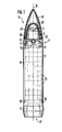
- a bomblet carrier body 1 is outlined in FIG. 1 as a projectile 2 that can be fired by a barrel weapon. It consists of a projectile tip 3 with sensor 4 and electronic signal processing device 5, an intermediate part 6 with ejection propellant 7, a projectile jacket 8 with ejection plate 9 and a projectile floor 10 with guide band 11.
- the bomblets 15 to be transported from the projectile 2 via the target area 12/13 (FIG. 2) and to be ejected there in the direction of the projectile longitudinal axis 14, opposite to the projectile flight direction, are arranged in the projectile casing 8 between the ejection plate 9 and the floor 10 , namely lined up in a rod shape and packed concentrically around the longitudinal axis 14 of the projectile.
- an ignition device 16 in the intermediate part 6 is triggered by the signal processing device 5, which ignites the ejection propellant 7.
- the pressure exerted on the ejection plate 9 in the direction of the projectile rear 17 is transmitted to the floor 10 via the rod-shaped packing of the bomblets 15; whose screw connection 18 shears off with the projectile jacket, so that the bomblets 15 are pushed out of the projectile 2 against the direction of flight by the now opened projectile rear.
- the contour of the projectile tip 8 is given by an aerodynamically shaped outer lens 19 made of highly durable material, in particular based on light metal. It is screwed to the side with an ogive base 20 on the back of the projectile tip 3.
- the detachable charges 21 arranged there can be used to detach the outer goggles 19 from the base 20, controlled from the signal processing device 5.
- the sensor 4 which is preferably designed as a millimeter-wave parabolic mirror 23 with a central axis lying in the longitudinal axis 14 of the floor, is arranged in the floor tip 3 behind the interior lens 22.
- the device for converting received electromagnetic signals into information is expediently structurally combined with this, and is evaluated by the signal processing device 5 arranged behind it for blasting off the ogives 19 and then for ejecting the bomblets 15.
- the carrier body 1 is designed - if necessary in accordance with the final phases - to approach the target area in a relatively steep dive.
- the sensor 4 for the construction and installation of the sensor 4, as mentioned, no particular effort is required; it suffices for a pick-up device which is permanently installed in the projectile tip 3 coaxially to it and oriented in advance, as is provided, for example, by the parabolic mirror 23 for millimeter waves,
- the target area 12 at the base 25 represents an oval-distorted circular area depending on the angle of fall and the flight movements of the support body 1. This area corresponds to the stray field over which the bomblets 15 spread over a standard height 24 of, e.g. Spread 300 m above ground 25.
- the target detection e.g. at a detection height 26 of 400 m above ground 25.
- the object of this target detection is the recording of reflection or intrinsic radiation from target objects 27 in the sensor detection area, which corresponds to an inner, reduced target area on ground 25; to which the stray field of the bomblets 15 could be reduced by delaying the bomblet output until a reduced height 29 above ground 25 is reached. Because of the reduced stray field, the bomblet output at this reduced height 29 results in a concentration of the bomblets 15 on the inner target area 13 and thus on the target object 27 located therein, which is attacked with the high density of almost all bomblets 15 and is most likely out of action is set.
- the effectiveness of the use of bomblets 15 against target objects 27 can be significantly increased by a simple variant of the sensor technology developed for combat observation and target detection here to delay the bomblet output until reaching a lower height 29, if in the inner target area 13 defined target object 27 was detected, is used.
Landscapes
- Engineering & Computer Science (AREA)
- General Engineering & Computer Science (AREA)
- Chemical & Material Sciences (AREA)
- Combustion & Propulsion (AREA)
- Aiming, Guidance, Guns With A Light Source, Armor, Camouflage, And Targets (AREA)
- Radar Systems Or Details Thereof (AREA)
Abstract
Description
- Die Erfindung betrifft ein Verfahren gemäß dem Oberbegriff des Anspruches 1 und einen Trägerkörper gemäß dem Oberbegriff des Anspruches 2.
- Das gattungsgemäße Verfahren und die gattungsgemäße Vorrichtung sind aus der DE-AS 17 03 781 bekannt. Die Zündung der Ausstoßtreibladung muß in solcher Höhe über Grund erfolgen, daß die - im wesentlichen parallel zur Einfallsrichtung in das Zielgebiet - aus dem Trägerkörper nach rückwärts ausgestoßenen Bomblets, deren steiler Flug ins Zielgebiet eine gegenseitige fächerförmige Aufweitung erfährt, eine hinreichend große Streu- und somit Zielfläche belegen; während andererseits, bei zu großflächigem Zielgebiet, aufgrund der beschränkten Anzahl von Bomblets in einem Trägerkörper die Wahrscheinlichkeit von Treffern bei einzelnen im Zielgebiet operierenden Zielobjekten nur gering ist.
- Der Erfindung liegt die Aufgabe zugrunde, die Wirkung der Bekämpfung einzelner Zielobjekte im Zielgebiet von Bomblets zu verbessern.
- Diese Aufgabe wird erfindungsgemäß im wesentlichen dadurch gelöst, daß das Verfahren gattungsgemäßer Art zusätzlich gemäß den Teilmerkmalen des kennzeichnenden Teils des Anspruches 1 ausgestaltet ist, während der Trägerkörper gattungsgemäßer Art auch die Teilmerkmale des kennzeichnenden Teils des Anspruches 2 aufweist.
- Der Kerngedanke der Lösung ist also darin zu sehen, den Trägerkörper nicht nur zur höhenabhängigen Steuerung für das Zün-den der Ausstoßtreibladung mit einem Sensor auszustatten;sondern auch diesen oder einen zusätzlichen Sensor dafür vorzusehen, - vor Herabfallen des Trägerkörpers auf die Standard- Höhe für den Ausstoß der Bomblets - einen inneren Bereich des Zielgebietes daraufhin zu untersuchen, ob sich darin ein spezifisches (vorgegebenes) zu bekämpfendes Zielobjekt befindet. Wenn das der Fall ist, erfolgt der Bomblet-Ausstoß noch nicht in der Standard-Hohe, sondern verzögert; und somit erst bei Erreichen einer reduzierten Höhe, aus der heraus das Bomblet-Streufeld im wesentlichen auf das kleinere Sensor-Erfassungsfeld im Inneren des größeren Standard-Zielgebietes konzentriert ist. In diesem Falle ist die Wirkung des Bomblet-Einsatzes erhöht, weil deren Einzel-Wirkungen im verkleinerten Zielgebiet und damit in unmittelbarer Nähe eines spezifisch zu bekämpfenden Zielobjektes konzentriert werden; mit der Folge entsprechend vergrößerter Wahrscheinlichkeit des erfolgreichen Einsatzes des Bomblet-Trägerkörpers. Wird dagegen beim Einfall in das Zielgebiet vom Sensor kein spezifisch zu bekäopfendes Zielobjekt in jenem inneren Zielgebiet ausgemacht, dann erfolgt der Ausstoß der Bomblets unverzögert; also bei Erreichen der Standard-Höhe mit dem entsprechend größeren Streubereich um das innere Zielgebiet herum, in dem die normale Wahrscheinlichkeit von Bomblet-Treffern in Zielobjekten gegeben ist, welche sich außerhalb des Sensor-Erfassungsgebietes befinden.
- Als Trägerkörper kann gleicherweise der Gefechtskopf eines Marschflugkörpers oder ein ballistisches Geschoß Anwendung finden, wenn durch seine ballistische oder gesteuerte Flugbahn ein genügend steiler Einfall des Trägerkörpers in das Zielgebiet gegeben ist. Denn dann lassen sich die Bomblets einfach auf das flächenmäßig verkleinerte, innere Zielgebiet konzentrieren, indem (bei rechtzeitiger Detektion eines darin befindlichen, spezifisch zu bekämpfenden Zielobjektes) der Bomblet-Ausstoß bis zum Erreichen einer niedrigeren Höhe über Ziel-Grund verzögert wird. Außerdem ist der konstruktive Aufwand für den Einbau und Betrieb des Sensors dann relativ gering, weil dieser starr und längs der Trägerkörper-Längsachse orientiert in dessen Spitze eingebaut werden kann.
- Auch der Sensor selbst kann einfach, also preiswert ausgebildet sein, da er weder hohe Auflösung noch starke Bündelung aufweisen muß. Vielmehr genügt es für die angestrebte Verbesserung des Bomblet-Einsatzes, daß er von knapp oberhalb der Ausstoß-Standardhöhe am Grund ein Erfassungsgebiet bedeckt, das kleiner als.das Standard-Streugebiet der Bomblets ist.
- Zusätzliche Weiterbildungen sowie weitere Merkmale und Vorteile der Erfindung ergeben sich aus nachstehender Beschreibung eines in der Zeichnung unter Beschränkung auf das Wesentliche stark vereinfacht dargestellten Prinzipbeispiels für eine erfindungsgemäße Vorrichtung zum Ausüben des erfindungsgemäßen Verfahrens.
Es zeigt: - Fig. 1 ein Geschoß als Bomblet-Trägerkörper, teilweise geschnitten, und
- Fig. 2 den Trägerkörper nach Absprengen seiner Außenogive in steilem Anflug auf den Ziel-Grund.
- Als Bomblet-Trägerkörper 1 ist in Fig. 1 eineαs einer Rohrwaffe verschießbares Geschoß 2 skizziert. Es besteht aus einer Geschoßspitze 3 mit Sensor 4 und elektronischer Signalverarbeitungseinrichtung 5, einem Zwischenteil 6 mit Ausstoßtreibladung 7, einem Geschoß-Mantel 8 mit Ausstoßplatte 9 sowie einem Geschoß-Boden 10 mit Führungsband 11.
- Die vom Geschoß 2 über das Zielgebiet 12/13 (Fig. 2) zu transportierenden und dort in Richtung der Geschoß-Längsachse 14, der Geschoß-Flugrichtung entgegen, auszustoßenden Bomblets 15 sind im Geschoß-Mantel 8 zwischen der Ausstoßplatte9 und dem Boden 10 angeordnet, nämlich stangenförmig aufgereiht und konzentrisch um die Geschoß-Längsachse 14 herum gepackt. Für den Ausstoß der Bomblets 15 wird von der Signalverarbeitungseinrichtung 5 eine Zündeinrichtung 16 im Zwischenteil 6 angesteuert, die die Ausstoßtreibladung 7 zündet. Der dadurch, in Richtung auf das Geschoß-Heck 17, auf die Ausstoßplatte 9 ausgeübte Druck wird über die stangenförmige Packung der Bomblets 15 auf den Boden 10 übertragen; dessen Verschraubung 18 mit dem Geschoß-Mantel abschert, so daß die Bomblets 15 durch das nun geöffnete Geschoß-Heck entgegen ihrer Flugrichtung aus dem Geschoß 2 herausgedrückt werden.
- Die Kontur der Geschoß-Spitze 8 ist durch eine strömungsgünstig geformte Außenogive 19 aus hoch-beanspruchbarem Werkstoff, insbesondere auf Leichtmetall-Basis, gegeben. Sie ist mit einem Ogiven-Sockel 20 an der Rückseite der Geschoß-Spitze 3 seitlich verschraubt. Mittels dort angeordneter Absprengladungen 21 ist die Außenogive 19 - gesteuert aus der Signalverarbeitungseinrichtung 5 heraus - vom Sockel 20 nach vorne absprengbar. Dadurch wird eine nach vorne als hohle Halbkugel ausgebildete Innenogive 22 freigelegt, deren Geometrie und Material nach Maßgabe der elektromagnetischen Strahlung, mit der der Sensor 4 arbeitet, ausgelegt ist, um Verzerrungen und Verluste beim Strahlungsdurchtritt durch die Innenogive 22 möglichst gering zu halten.
- Hinter der Innenogive 22 ist in der Geschoß-Spitze 3 der Sensor 4 angeordnet, der bevorzugt als Millimeterwellen-Parabolspiegel 23 mit in der Geschoß-Längsachse 14 liegender Mittenachse ausgebildet ist. Zweckmäßigerweise baulich mit diesem vereint ist die Einrichtung zur Umsetzung empfangener elektromagnetischer Signale in Informationen, die von der dahinter angeordneten Signalverarbeitungs-Einrichtung 5 zum Absprengen der Außenogive 19 und danach zum Ausstoßen der Bomblets 15 ausgewertet werden.
- Der Trägerkörper 1 ist dafür ausglegt - gegebenenfalls entsprechend endphasen-gesteuert -, sich in relativ steilem Sturzflug dem Zielgebiet zu nähern. Für den Aufbau und Einbau des Sensors 4 braucht, wie erwähnt, kein besonderer Aufwand getrieben zu werden; es genügt eine in der Geschoß-Spitze 3 koaxial zu ihr fest eingebaute und voraus orientierte Aufnehmereinrichtung, wie sie etwa durch den Parabolspiegel 23 für Millimeterwellen gegeben ist,
- Das Zielgebiet 12 am Grund 25 stellt eine nach Maßgabe des Fallwinkels und der Flugbewegungen des Trägerkörpers 1 zeitabhängig oval-verzerrte Kreisfläche dar. Diese Fläche entspricht dem Streufeld, über das die Bomblets 15 sich bei einem Ausstoß in Standard-Höhe 24 von,z.B. 300 m über Grund 25 verteilen.
- Schon oberhalb dieser Standard-Höhe 24, nachdem die Außenogive 19 abgesprengt wurde, beginnt mittels des Sensors 4 die Zieldetektion, z.B. in einer Detektionshöhe 26 von 400 m über Grund 25. Gegenstand dieser Zieldetektion ist die Aufnahme von Reflexions- oder Eigenstrahlung von Zielobjekten 27 im Sensor-Erfassungsgebiet,dem auf dem Grund 25 ein inneres, reduziertes Zielgebiet entspricht; auf das das Streufeld der Bomblets 15 reduziert werden könnte, indem der Bomblet-Ausstoß bis zum Erreichen einer reduzierten Höhe 29 über Grund 25 verzögert wird. Der Bomblet-Ausstoß in dieser reduzierten Höhe 29 erbringt wegen des reduzierten Streufeldes eine Konzentration der Bomblets 15 auf das innere Zielgebiet 13 und somit auf das darin befindliche Zielobjekt 27, das so mit der hohen Dichte fast aller Bomblets 15 angegriffen und mit größter Wahrscheinlichkeit außer Gefecht gesetzt wird. So ist die Wirksamkeit des Einsatzes von Bomblets 15 gegen Zielobjekte 27 wesentlich vergrößerbar, indem eine einfache Variante der für die Gefechts-Beobachtung und Zieldetektion entwickelten Sensortechnik hier zur Verzögerung des Bomblet-Ausstoßes bis zum Erreichen einer niedrigeren Höhe 29, wenn im inneren Zielgebiet 13 ein definiertes Zielobjekt 27 erfasst wurde, eingesetzt wird.
- Wenn sich dagegen im Inneren 13 des insgesamt von Bomblets 15 erfaßbaren Zielgebietes 12 kein spezifisch zu bekämpfendes Zielobjekt 27 - dessen Strahlungs- oder Geometrie-Parameter in der Signalverarbeitungseinrichtung 5 für eine Zielselektion vorgegeben sind - ausmachen lässt, dann erfolgt wie üblich der Bomblet-Ausstoß schon bei Erreichen der Standard- Höhe 24, zur Verteilung der Bomblets 15 über dieses Standard-Streufeld als dem normalen Zielgebiet 12. Darin vorhandene Zielobjekte 28 können zwar nicht mit der hohen Dichte aller Bomblets 15 bekämpft werden; aber es besteht die normale Wahrscheinlichkeit, wenigstens mit einigen der ausgestreuten Bomblets 15 Treffer zu erzielen und zumindest kampfwertmindernde Beschädigungen an den Zielobjekten 28 hervorzurufen.
-
- 1 Trägerkörper (z.B. 2)
- 2 Geschoß (mit 15)
- 3 Spitze (von 2)
- 4 Sensor (in 3)
- 5 Signalverarbeitungseinrichtung (für 4 und 21/7)
- 6 Zwischenteil (zwischen 3 und 8)
- 7. Ausstoßtreibladung (in 6 vor 9)
- 8 Mantel (um 9 und 15)
- 9 Ausstoßplatte (vor 15)
- 10 Boden (an 8/17 hinter 15)
- 11 FUhrungsband (um 17/10)
- 12 Standard-Zielgebiet (für 24)
- 13 inneres Zielgebiet (für 29)
- 14 Längsachse (von 1, 2, 4)
- 15 Bomblets (in 1/8)
- 16 Zündeinrichtung (für 7)
- 17 Heck (von 2/8)
- 18 Verschraubung (zwischen 10 und 8)
- 19 Außenogive (von 3)
- 20 Sockel (in 3 für 19 und 22)
- 21 Absprengladung (in 20 für 19)
- 22 Innenogive (vor 4)
- 23 Parabolspiegel (von 4 hinter 22)
- 24 Standard-Höhe (zum Ausstoßen von 15 über 12 an 25)
- 25 Grund
- 26 Detektionshöhe (oberhalb 24)
- 27 Zielobjekt (in 13)
- 28 Zielobjekt (außerhalb 13 in 12)
- 29 reduzierte Höhe (zum Ausstoßen von 15 über 13 im Zentrum von 12 an 25)
Claims (7)
dadurch gekennzeichnet,
daß beim Einfall des Trägerkörpers in ein Zielgebiet der Ausstoß der Bomblets bis zum Erreichen einer gegenüber Standard-Höhe reduzierten Höhe verzögert wird, wenn vor Erreichen der Standard-Höhe im flächenmäßig entsprechend kleineren Streu- und Zielgebiet ein Zielobjekt ausgemacht wurde.
daß ein Sensor (4) eingebaut ist, dessen Erfassungsgebiet in einer Detektions-Höhe (26) wesentlich kleiner als das Zielgebiet (12) bei Bomblet-Ausstoß in Standard-Höhe (24) ist und der bei Detektion eines vorgegebenen Zielobjektes (27) in seinem Erfassungsgebiet,vor Erreichen der Standard-Höhe (24),die Ausstoßtreibladung (7) noch nicht in der Standard-Höhe (24) zündet, sondern erst bei einer reduzierten Höhe (29) für ein entsprechend kleineres, inneres Zielgebiet (13), das dem Sensor-Erfassungsgebiet aus der Detektions-Höhe (26) oberhalb der Standard-Hohe (24) etwa entspricht.
daß der Sensor (4) in der Trägerkörper-Spitze (3) koaxial voraus ausgerichtet ist.
daß die Trägerkörper-Spitze (3) mit einer der Sensor-Funktion angepassten Innenogive (22) und einer diese umgebenden, flugdynamisch günstiger gestalteten, absprengbaren Außenogive (19) ausgestattet ist.
daß der Sensor (4) eine Absprengladung (21) zündet, ehe der Trägerkörper (1) auf eine vorgegebene Detektions-Höhe (26) oberhalb der Ausstoß-Standardhöhe (24) herabgefallen ist.
daß der Sensor (4) mit einem Millimeterwellen-Parabolspiegel (23) ausgestattet ist.
daß er als Geschoß (2) ausgebildet ist.
Applications Claiming Priority (2)
| Application Number | Priority Date | Filing Date | Title |
|---|---|---|---|
| DE19833319824 DE3319824A1 (de) | 1983-06-01 | 1983-06-01 | Verfahren zum bekaempfen von zielobjekten mittels bomblets und bomblet-traegerkoerper zum ausueben des verfahrens |
| DE3319824 | 1983-06-01 |
Publications (2)
| Publication Number | Publication Date |
|---|---|
| EP0127805A1 true EP0127805A1 (de) | 1984-12-12 |
| EP0127805B1 EP0127805B1 (de) | 1987-08-26 |
Family
ID=6200390
Family Applications (1)
| Application Number | Title | Priority Date | Filing Date |
|---|---|---|---|
| EP84105385A Expired EP0127805B1 (de) | 1983-06-01 | 1984-05-12 | Bomblet-Trägerkörper zum Bekämpfen von Zielobjekten mittels Bomblets |
Country Status (4)
| Country | Link |
|---|---|
| US (1) | US4583461A (de) |
| EP (1) | EP0127805B1 (de) |
| DE (2) | DE3319824A1 (de) |
| IL (1) | IL71729A (de) |
Cited By (3)
| Publication number | Priority date | Publication date | Assignee | Title |
|---|---|---|---|---|
| EP0162250A1 (de) * | 1984-04-17 | 1985-11-27 | Dynamit Nobel Aktiengesellschaft | Flugkörper mit einem fernwirkenden Gefechtskopf |
| WO1986006470A1 (en) * | 1985-04-25 | 1986-11-06 | Rheinmetall Gmbh | Process for operating a proximity fuse, and device for the implementation of the process |
| FR2701558A1 (fr) * | 1993-02-11 | 1994-08-19 | Diehl Gmbh & Co | Procédé et dispositif pour attaquer des cibles avec des sous-munitions. |
Families Citing this family (10)
| Publication number | Priority date | Publication date | Assignee | Title |
|---|---|---|---|---|
| US4750423A (en) * | 1986-01-31 | 1988-06-14 | Loral Corporation | Method and system for dispensing sub-units to achieve a selected target impact pattern |
| US4750403A (en) * | 1986-01-31 | 1988-06-14 | Loral Corporation | Spin dispensing method and apparatus |
| US4676167A (en) * | 1986-01-31 | 1987-06-30 | Goodyear Aerospace Corporation | Spin dispensing method and apparatus |
| SE452505B (sv) * | 1986-03-27 | 1987-11-30 | Bofors Ab | Substridsdel med svengbart anordnad maldetektor |
| DE3631078A1 (de) * | 1986-09-12 | 1988-03-24 | Diehl Gmbh & Co | Submunitionskoerper mit seitlich herausbewegbarer zieldetektionseinrichtung |
| DE3739370A1 (de) * | 1987-11-20 | 1989-06-01 | Diehl Gmbh & Co | Bomblet-gefechtskopf |
| US6003809A (en) * | 1997-02-25 | 1999-12-21 | Honigsbaum; Richard F. | Process and apparatus for discouraging countermeasures against a weapon transport device |
| DE10249920A1 (de) * | 2002-10-26 | 2004-05-13 | Diehl Munitionssysteme Gmbh & Co. Kg | Nebelgeschoss |
| DE102004053449B4 (de) * | 2004-11-05 | 2010-12-09 | Diehl Bgt Defence Gmbh & Co. Kg | Vorsatzhaube |
| US8141468B2 (en) | 2009-03-17 | 2012-03-27 | Raytheon Company | Adjustable bomb carrier |
Citations (8)
| Publication number | Priority date | Publication date | Assignee | Title |
|---|---|---|---|---|
| US2782716A (en) * | 1953-11-30 | 1957-02-26 | North American Aviation Inc | Destructible cover for fragile dome |
| FR1203886A (fr) * | 1958-07-04 | 1960-01-21 | Aeronautique Soc Ind | Mécanisme autodirecteur à détection optique, notamment pour mobiles du type des engins spéciaux |
| US2961954A (en) * | 1943-02-01 | 1960-11-29 | Harry H Moore | Depth charge firing mechanism |
| FR1605069A (de) * | 1966-12-01 | 1973-01-12 | ||
| US3726223A (en) * | 1970-02-16 | 1973-04-10 | Us Navy | Adaptive warhead |
| DE2364195A1 (de) * | 1973-12-22 | 1975-06-26 | Messerschmitt Boelkow Blohm | Zielbekaempfungsverfahren fuer multi- gefechtskoepfe |
| US4072107A (en) * | 1967-06-07 | 1978-02-07 | The United States Of America As Represented By The Secretary Of The Army | Missile control means |
| EP0049778A1 (de) * | 1980-10-10 | 1982-04-21 | Hüls Troisdorf Aktiengesellschaft | Verfahren zum Verteilen von Gefechtskörpern |
Family Cites Families (7)
| Publication number | Priority date | Publication date | Assignee | Title |
|---|---|---|---|---|
| US4128836A (en) * | 1960-10-14 | 1978-12-05 | The United States Of America As Represented By The Secretary Of The Army | Time delay computer for ordnance fuse |
| US4185560A (en) * | 1962-01-31 | 1980-01-29 | Mayer Levine | Fore and aft fuzing system |
| US4320703A (en) * | 1966-05-27 | 1982-03-23 | United States Of America As Represented By The Secretary Of The Navy | Target detecting device |
| US3611931A (en) * | 1969-05-05 | 1971-10-12 | Murell J Bessey | Sequential burst air drop cluster |
| NO139982C (no) * | 1976-10-26 | 1979-06-13 | Kongsberg Vapenfab As | Missil til utskytning mot et maal. |
| US4444117A (en) * | 1981-03-30 | 1984-04-24 | The Boeing Company | Stacked tube submunition dispenser |
| US4455943A (en) * | 1981-08-21 | 1984-06-26 | The Boeing Company | Missile deployment apparatus |
-
1983
- 1983-06-01 DE DE19833319824 patent/DE3319824A1/de not_active Withdrawn
-
1984
- 1984-05-02 IL IL71729A patent/IL71729A/xx unknown
- 1984-05-12 DE DE8484105385T patent/DE3465624D1/de not_active Expired
- 1984-05-12 EP EP84105385A patent/EP0127805B1/de not_active Expired
- 1984-05-25 US US06/614,742 patent/US4583461A/en not_active Expired - Fee Related
Patent Citations (8)
| Publication number | Priority date | Publication date | Assignee | Title |
|---|---|---|---|---|
| US2961954A (en) * | 1943-02-01 | 1960-11-29 | Harry H Moore | Depth charge firing mechanism |
| US2782716A (en) * | 1953-11-30 | 1957-02-26 | North American Aviation Inc | Destructible cover for fragile dome |
| FR1203886A (fr) * | 1958-07-04 | 1960-01-21 | Aeronautique Soc Ind | Mécanisme autodirecteur à détection optique, notamment pour mobiles du type des engins spéciaux |
| FR1605069A (de) * | 1966-12-01 | 1973-01-12 | ||
| US4072107A (en) * | 1967-06-07 | 1978-02-07 | The United States Of America As Represented By The Secretary Of The Army | Missile control means |
| US3726223A (en) * | 1970-02-16 | 1973-04-10 | Us Navy | Adaptive warhead |
| DE2364195A1 (de) * | 1973-12-22 | 1975-06-26 | Messerschmitt Boelkow Blohm | Zielbekaempfungsverfahren fuer multi- gefechtskoepfe |
| EP0049778A1 (de) * | 1980-10-10 | 1982-04-21 | Hüls Troisdorf Aktiengesellschaft | Verfahren zum Verteilen von Gefechtskörpern |
Non-Patent Citations (1)
| Title |
|---|
| MILITARY MICROWAVES '82, 20.-22. Oktober 1982, London, GB, pages 133-140, Microwave exhibitions and Publishers Ltd., Kent, GB; S.L. JOHNSTON: "Millimeter wave anti-tank guided missiles" * |
Cited By (5)
| Publication number | Priority date | Publication date | Assignee | Title |
|---|---|---|---|---|
| EP0162250A1 (de) * | 1984-04-17 | 1985-11-27 | Dynamit Nobel Aktiengesellschaft | Flugkörper mit einem fernwirkenden Gefechtskopf |
| US4823700A (en) * | 1984-04-17 | 1989-04-25 | Dynamit Nobel Aktiengesellschaft | Missile with remote-controlled warhead |
| WO1986006470A1 (en) * | 1985-04-25 | 1986-11-06 | Rheinmetall Gmbh | Process for operating a proximity fuse, and device for the implementation of the process |
| US4773328A (en) * | 1985-04-25 | 1988-09-27 | Rheinmetall Gmbh | Method of actuating a proximity fuze and device for implementing the method |
| FR2701558A1 (fr) * | 1993-02-11 | 1994-08-19 | Diehl Gmbh & Co | Procédé et dispositif pour attaquer des cibles avec des sous-munitions. |
Also Published As
| Publication number | Publication date |
|---|---|
| DE3319824A1 (de) | 1984-12-06 |
| US4583461A (en) | 1986-04-22 |
| IL71729A (en) | 1991-05-12 |
| DE3465624D1 (en) | 1987-10-01 |
| EP0127805B1 (de) | 1987-08-26 |
Similar Documents
| Publication | Publication Date | Title |
|---|---|---|
| CH626442A5 (de) | ||
| EP0127805A1 (de) | Bomblet-Trägerkörper zum Bekämpfen von Zielobjekten mittels Bomblets | |
| DE3510446A1 (de) | Treibsatz zur bodensogreduzierung | |
| DE102007032112A1 (de) | Verfahren und Abschussvorrichtung zum Schutz eines Objektes vor einer Bedrohung, insbesondere einem Flugkörper, sowie Munition | |
| DE2936861A1 (de) | Kartusche zum ausstreuen elektromagnetischer scheinziele, insbesondere aus einem luftfahrzeug | |
| DE3633535C1 (de) | Gefechtskopf | |
| DE2908217C2 (de) | Einheitsladung zur Vernebelung von Fahrzeugen | |
| DE2034618A1 (de) | Gegen ein Ziel bewegbares Geschoss | |
| DE3228461C2 (de) | Endphasengelenkter Abwurfkörper | |
| CH636696A5 (de) | Geschoss. | |
| DE3326748C2 (de) | ||
| DE3009774A1 (de) | Geschoss, insbesondere panzerbrechendes geschoss | |
| DE3536328A1 (de) | Fremdkoerperabwehrsystem | |
| EP3698097B1 (de) | Täuschkörper | |
| DE69817496T2 (de) | Hohlladungsprojektil und dazugehöriges Waffensystem | |
| DE3821218A1 (de) | Verfahren zum bekaempfen eines zielobjektes von einem ueberflugprojektil aus und ueberflugprojektil zum ausueben des verfahrens | |
| DE4034618C2 (de) | Mine | |
| DE3820183A1 (de) | Flugkoerper mit einem schwenkbaren gefechtskopf | |
| DE3311075C2 (de) | ||
| DE3740412C1 (de) | Gefechtskopf | |
| EP0698774A1 (de) | Drallstabilisiertes Geschoss mit einer Nutzlast | |
| DE2810336C2 (de) | Rauch-, Nebelkörper o.dgl. | |
| DE2533585A1 (de) | Gefechtskopf zur bekaempfung von raeumlichen zielen, insbesondere schiffen | |
| DE2516208C3 (de) | Im Flug zerlegbare Artillerie-Pilotrakete | |
| AT407443B (de) | Splittermine |
Legal Events
| Date | Code | Title | Description |
|---|---|---|---|
| PUAI | Public reference made under article 153(3) epc to a published international application that has entered the european phase |
Free format text: ORIGINAL CODE: 0009012 |
|
| AK | Designated contracting states |
Designated state(s): CH DE FR GB IT LI NL SE |
|
| 17P | Request for examination filed |
Effective date: 19841017 |
|
| 17Q | First examination report despatched |
Effective date: 19860325 |
|
| GRAA | (expected) grant |
Free format text: ORIGINAL CODE: 0009210 |
|
| AK | Designated contracting states |
Kind code of ref document: B1 Designated state(s): CH DE FR GB IT LI NL SE |
|
| REF | Corresponds to: |
Ref document number: 3465624 Country of ref document: DE Date of ref document: 19871001 |
|
| ITF | It: translation for a ep patent filed |
Owner name: STUDIO JAUMANN |
|
| ET | Fr: translation filed | ||
| PLBE | No opposition filed within time limit |
Free format text: ORIGINAL CODE: 0009261 |
|
| STAA | Information on the status of an ep patent application or granted ep patent |
Free format text: STATUS: NO OPPOSITION FILED WITHIN TIME LIMIT |
|
| 26N | No opposition filed | ||
| PGFP | Annual fee paid to national office [announced via postgrant information from national office to epo] |
Ref country code: SE Payment date: 19890530 Year of fee payment: 6 |
|
| PG25 | Lapsed in a contracting state [announced via postgrant information from national office to epo] |
Ref country code: SE Effective date: 19900513 |
|
| PGFP | Annual fee paid to national office [announced via postgrant information from national office to epo] |
Ref country code: CH Payment date: 19910410 Year of fee payment: 8 |
|
| PGFP | Annual fee paid to national office [announced via postgrant information from national office to epo] |
Ref country code: FR Payment date: 19910429 Year of fee payment: 8 |
|
| PGFP | Annual fee paid to national office [announced via postgrant information from national office to epo] |
Ref country code: GB Payment date: 19910502 Year of fee payment: 8 |
|
| ITTA | It: last paid annual fee | ||
| PGFP | Annual fee paid to national office [announced via postgrant information from national office to epo] |
Ref country code: NL Payment date: 19910531 Year of fee payment: 8 |
|
| PGFP | Annual fee paid to national office [announced via postgrant information from national office to epo] |
Ref country code: DE Payment date: 19910719 Year of fee payment: 8 |
|
| PG25 | Lapsed in a contracting state [announced via postgrant information from national office to epo] |
Ref country code: GB Effective date: 19920512 |
|
| PG25 | Lapsed in a contracting state [announced via postgrant information from national office to epo] |
Ref country code: LI Effective date: 19920531 Ref country code: CH Effective date: 19920531 |
|
| PG25 | Lapsed in a contracting state [announced via postgrant information from national office to epo] |
Ref country code: NL Effective date: 19921201 |
|
| GBPC | Gb: european patent ceased through non-payment of renewal fee |
Effective date: 19920512 |
|
| NLV4 | Nl: lapsed or anulled due to non-payment of the annual fee | ||
| PG25 | Lapsed in a contracting state [announced via postgrant information from national office to epo] |
Ref country code: FR Effective date: 19930129 |
|
| REG | Reference to a national code |
Ref country code: CH Ref legal event code: PL |
|
| PG25 | Lapsed in a contracting state [announced via postgrant information from national office to epo] |
Ref country code: DE Effective date: 19930202 |
|
| REG | Reference to a national code |
Ref country code: FR Ref legal event code: ST |
|
| EUG | Se: european patent has lapsed |
Ref document number: 84105385.3 Effective date: 19910115 |