EP0065116B1 - Fahrzeugsitz - Google Patents
Fahrzeugsitz Download PDFInfo
- Publication number
- EP0065116B1 EP0065116B1 EP82103345A EP82103345A EP0065116B1 EP 0065116 B1 EP0065116 B1 EP 0065116B1 EP 82103345 A EP82103345 A EP 82103345A EP 82103345 A EP82103345 A EP 82103345A EP 0065116 B1 EP0065116 B1 EP 0065116B1
- Authority
- EP
- European Patent Office
- Prior art keywords
- shell
- vehicle seat
- longitudinal
- edge
- spar
- Prior art date
- Legal status (The legal status is an assumption and is not a legal conclusion. Google has not performed a legal analysis and makes no representation as to the accuracy of the status listed.)
- Expired
Links
- 239000002184 metal Substances 0.000 claims description 16
- 238000003466 welding Methods 0.000 description 5
- 230000009189 diving Effects 0.000 description 4
- 230000002349 favourable effect Effects 0.000 description 2
- 230000006866 deterioration Effects 0.000 description 1
- 238000007654 immersion Methods 0.000 description 1
- 230000000399 orthopedic effect Effects 0.000 description 1
- 230000001681 protective effect Effects 0.000 description 1
- 230000002787 reinforcement Effects 0.000 description 1
- 230000000284 resting effect Effects 0.000 description 1
- IHQKEDIOMGYHEB-UHFFFAOYSA-M sodium dimethylarsinate Chemical class [Na+].C[As](C)([O-])=O IHQKEDIOMGYHEB-UHFFFAOYSA-M 0.000 description 1
Images
Classifications
-
- B—PERFORMING OPERATIONS; TRANSPORTING
- B60—VEHICLES IN GENERAL
- B60N—SEATS SPECIALLY ADAPTED FOR VEHICLES; VEHICLE PASSENGER ACCOMMODATION NOT OTHERWISE PROVIDED FOR
- B60N2/00—Seats specially adapted for vehicles; Arrangement or mounting of seats in vehicles
- B60N2/02—Seats specially adapted for vehicles; Arrangement or mounting of seats in vehicles the seat or part thereof being movable, e.g. adjustable
- B60N2/0284—Adjustable seat-cushion length
-
- B—PERFORMING OPERATIONS; TRANSPORTING
- B60—VEHICLES IN GENERAL
- B60N—SEATS SPECIALLY ADAPTED FOR VEHICLES; VEHICLE PASSENGER ACCOMMODATION NOT OTHERWISE PROVIDED FOR
- B60N2/00—Seats specially adapted for vehicles; Arrangement or mounting of seats in vehicles
- B60N2/24—Seats specially adapted for vehicles; Arrangement or mounting of seats in vehicles for particular purposes or particular vehicles
- B60N2/42—Seats specially adapted for vehicles; Arrangement or mounting of seats in vehicles for particular purposes or particular vehicles the seat constructed to protect the occupant from the effect of abnormal g-forces, e.g. crash or safety seats
- B60N2/4249—Seats specially adapted for vehicles; Arrangement or mounting of seats in vehicles for particular purposes or particular vehicles the seat constructed to protect the occupant from the effect of abnormal g-forces, e.g. crash or safety seats fixed structures, i.e. where neither the seat nor a part thereof are displaced during a crash
- B60N2/4256—Seats specially adapted for vehicles; Arrangement or mounting of seats in vehicles for particular purposes or particular vehicles the seat constructed to protect the occupant from the effect of abnormal g-forces, e.g. crash or safety seats fixed structures, i.e. where neither the seat nor a part thereof are displaced during a crash the shape of the seat being specially adapted for a particular purpose or for particular vehicles
- B60N2/4263—Seats specially adapted for vehicles; Arrangement or mounting of seats in vehicles for particular purposes or particular vehicles the seat constructed to protect the occupant from the effect of abnormal g-forces, e.g. crash or safety seats fixed structures, i.e. where neither the seat nor a part thereof are displaced during a crash the shape of the seat being specially adapted for a particular purpose or for particular vehicles with anti-submarining systems
-
- B—PERFORMING OPERATIONS; TRANSPORTING
- B60—VEHICLES IN GENERAL
- B60N—SEATS SPECIALLY ADAPTED FOR VEHICLES; VEHICLE PASSENGER ACCOMMODATION NOT OTHERWISE PROVIDED FOR
- B60N2/00—Seats specially adapted for vehicles; Arrangement or mounting of seats in vehicles
- B60N2/62—Thigh-rests
-
- B—PERFORMING OPERATIONS; TRANSPORTING
- B60—VEHICLES IN GENERAL
- B60N—SEATS SPECIALLY ADAPTED FOR VEHICLES; VEHICLE PASSENGER ACCOMMODATION NOT OTHERWISE PROVIDED FOR
- B60N2/00—Seats specially adapted for vehicles; Arrangement or mounting of seats in vehicles
- B60N2/68—Seat frames
Definitions
- the invention relates to a vehicle seat which has the features of the preamble of claim 1.
- the invention has for its object to provide a vehicle seat that allows to achieve the required high stability with minimal ' weight with reduced effort and also to provide adequate diving protection for the upholstery with the least possible effort.
- a circular cylindrical. Pipe as a rear cross member is less expensive than a hollow profile rod made of sheet metal shells and, for the stresses to be absorbed by this cross member, is just as favorable in terms of the ratio of stability and weight as a hollow box made of shells.
- such a tube can serve as a journal for a swiveling backrest, which also enables savings in weight and costs.
- the front cross member as a sheet metal part formed from a single, upwardly curved sheet metal plate, the costs can be reduced without a deterioration in the relationship between stability and weight. Since such a sheet metal part does not require any protruding strips, it is also suitable, without protective covers and the like, to form a diving protection for the upholstery in the event of a crash. This immersion protection is particularly effective if the rear part of the sheet metal plate forming the front cross member forms a support surface inclined backwards and downwards for the associated cushion support.
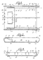
- FIGS. 1 to 3 show a part of the seat frame of a motor vehicle seat in the assembled state, specifically the part of the seat frame assigned to the seat part.
- the frame part assigned to the backrest is not shown.
- the part of the seat frame shown has two longitudinal spars 11 and 13 which run parallel to one another in the longitudinal direction of the seat and which are connected to one another via a front transverse spar and a rear transverse spar and are embodied as mirror images of one another.
- the front cross member is, as can best be seen from FIGS. 1, 4 and 7, formed as a molded part 15 made of sheet metal, which has lateral, raised edges 17, 18 (FIGS. 4 and 7) with the longitudinal members 11 and 13 welded. is.
- the rear cross member is designed in the form of a connecting tube 16 which is welded to the longitudinal members 11 and 13 at its tube ends 19 and 21. The pipe ends 19 and 21 pass through the longitudinal spars 11 and 13, whereby protruding pipe stubs are formed.
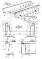
- the longitudinal spars are each formed from an outer shell 23, 25 and an inner shell 27, 29, the outer shells 23 and 25 being mirror images of one another, as is also the case with the inner shells 27 and 29 is the case.
- the outer shells 23, 25 have a substantially flat wall 31 and 33 as the shell bottom, which forms with its outside or back the outer broad side of the relevant longitudinal spar 11 or 13 lying in a vertical plane.
- the walls 31, 33 of the outer shells 23 and 25 are pierced by a plurality of bores, of which the bores 34 and 35 adjacent to the rear end serve for the passage of the tube ends 19 and 21, respectively.
- bores 37 and 39 which are displaced forward, serve as bearings for actuating and / or actuating devices, not shown, of an articulated fitting, not shown, which is also not shown Backrest which can be locked with the projecting tube ends 19 and 21 of the connecting tube 16.
- the walls 31 and 33 forming the shell bottom of the outer shells 23, 25 are bordered on the two narrow sides and on the upper broad side by an inwardly bent, continuous edge 41 and 42 which is bent at right angles in the illustrated embodiment. As can be seen in particular in FIG. 4 for the outer shell 23, this edge 41, 42 merges at its lower ends into a lower edge, which is designated 38 in the outer shell 23 and 40 in the outer shell 25.
- the edges 38 and 40 are widened inward over a large part of the length of the underside, so that horizontally extending, wide fastening strips 43, 44 are formed.
- the inner shells 27 and 29 of the longitudinal spars 11 and 13 also have a substantially flat wall as the shell bottom, which is designated 45 in the inner shell 27 and 46 in the inner shell 29.
- these walls 45 and 46 form the inner broad sides of the longitudinal spars 11 and 13.
- the walls 45 and 46 are, as is also the case with the outer shells 23, 25, bordered by bent edges, on the underside of one right-angled inward edge, which is designated 47 on the inner shell 27 and 49 on the inner shell 29.
- the edges 47 and 49 lie flush on the part of the lower edges 38 and 40 of the associated outer shells 23 and 25 forming the fastening strips 43 and 44, as can best be seen from FIG. 5.
- the edge 50 or 51 enclosing the wall 45 or 46 is bent towards the opposite side, that is to say against the associated outer shell 23 or 25.
- This edge 50 or 51 of the inner shells 27 and 29 has an inwardly bent end region in the form of an inwardly open U-profile 53 or 55.
- the U-profile 53, 55 lies with the outside of its web 57 or 59 on the inside of the wall 31 or 33 of the shell bottom of the outer shell 23 or 25, while the outer leg 61 or 63 of the U- Profile 53 or 55 with its outer side rests on the inner side of the adjacent edge 41, 42 of the associated outer shell 23 or 25.
- the shells are firmly connected to one another along the contact surfaces of their edges, in the exemplary embodiment by spot welding.
- fastening holes 65, 66 are provided in the fastening strips 43 and 44 and in the edges 47 and 49 of the inner shells 27 and 29 resting thereon as reinforcements, which are aligned with one another when the longitudinal spar is assembled and by means of which the longitudinal spars are connected via a Intermediate unit (console or the like) can be connected to the vehicle floor.
- a Intermediate unit (console or the like) can be connected to the vehicle floor.
- depressions 69 and 70 are provided which are pressed in from the rear of the shell bottom of the inner shell and form depressions which allow free access to the holes 66 .
- the shell bottom of the inner shells 27 and 29 are also provided with the holes 37 and 39 aligned holes 71 and 72, which form a continuous support for the already mentioned mechanism intended for the actuation of the backrest on each longitudinal spar 11 and 13.
- a bore 73 and 75 for the passage of the connecting tube 16 is provided in the wall 45 and 46 of each inner shell 27 and 29.
- the molded part 15 provided as the front cross member is, as can be seen in FIGS. 1, 2 and 4, in the form of a curved sheet metal plate which runs from longitudinal to longitudinal beam.
- a step-shaped bulge 20 is formed upward from the support surface 14.
- This bulge has four bores 22 in its rear wall. Together with corresponding bores 12 in the front end face area of the molded part 15, these form four identical guides running in the longitudinal direction of the vehicle, in which support rods are mounted so as to be longitudinally displaceable.
- each front part can be set separately as a base for one lower leg of the user, which u. a. -for example in an orthopedic seat is advantageous.
- FIGS. 4 and 7 The attachment of the front cross member to the longitudinal spars 11 and 13 can be seen most clearly from FIGS. 4 and 7.
- the raised front edge 17 of the molded part 15 lies against the inner surface of the web 57, 59 of the U-profile 53 or 55 of the inner shell 27 or 29 of the associated longitudinal spar, where it is fastened by welding.
Landscapes
- Engineering & Computer Science (AREA)
- Aviation & Aerospace Engineering (AREA)
- Transportation (AREA)
- Mechanical Engineering (AREA)
- Seats For Vehicles (AREA)
Description
- Die Erfindung betrifft einen Fahrzeugsitz, welcher die Merkmale des Oberbegriffs des Anspruches 1 aufweist.
- Bei einem bekannten Fahrzeugsitz dieser Art . (US-A-27 20 914) bestehen sämtliche Holme aus je zwei miteinander verbundenen Blechschalen, die je einen Hohlprofilstab mit zwei von diesem nach außen abstehenden, sich über die gesamte Stablänge erstreckenden Leisten bilden, wobei diese Leisten aus den aneinander anliegenden und miteinander verbundenen Randzonen der beiden Blechschalen bestehen. Derartige Holme lassen zwar ein günstiges Verhältnis zwischen Gewicht und Belastbarkeit erreichen. Sie sind jedoch relativ aufwendig und ihre Leisten können in einem Crash-Fall zumindest dann den Sitzbenutzer gefährden, wenn sie gegen die Bewegungsrichtung des Sitzbenutzers relativ zum Rahmen gerichtet sind, wie dies bei den Leisten des vorderen Querholmes der Fall ist, welche nach oben bzw. gegen den hinteren Querholm weisen.
- Der Erfindung liegt die Aufgabe zugrunde, einen Fahrzeugsitz zu schaffen, der es ermöglicht, mit vermindertem Aufwand die erforderliche hohe Stabilität bei minimalen 'Gewicht zu erreichen und außerdem mit möglichst geringem Aufwand einen ausreichenden Tauchschutz für die Polsterung zu bieten.
- Diese Aufgabe löst ein Fahrzeugsitz mit den Merkmalen des Patentanspruches 1.
- Ein kreiszylindrisches . Rohr als hinterer Querholm ist kostengünstiger als ein aus Blechschalen gebildeter Hohlprofilstab und für die von diesem Querholm aufzunehmenden Beanspruchungen ebenso günstig hinsichtlich des Verhältnisses von Stabilität und Gewicht wir ein aus Schalen gebildeter Hohlkasten. Hinzu kommt, daß ein solches Rohr als Lagerzapfen für eine schwenkbare Rückenlehne dienen kann, was ebenfalls Einsparungen an Gewicht und Kosten ermöglicht. Durch die Gestaltung des vorderen Querholms als ein aus einer einzigen, nach oben gewölbten Blechplatte gebildetes Blechteil lassen sich die Kosten ohne eine Verschlechterung des Verhältnisses zwischen Stabilität und Gewicht reduzieren. Da ein solches Blechteil keine abstehenden Leisten benötigt, ist es ferner ohne Schutzabdeckungen und dergleichen geeignet, einen Tauchschutz für die Polsterung im Crash-Fall zu bilden. Dieser Tauchschutz ist besonders effektiv, wenn der rückwärtige Teil der den vorderen Querholm bildenden Blechplatte eine nach hinten und unten geneigte Auflagefläche für den zugehörigen Polsterträger bildet..
- Weitere vorteilhafte Ausgestaltungsmöglichkeiten der einzelnen Teile des Sitzrahmens sind Gegenstand der Patentansprüche 3-9.
- Die Erfindung wird nachfolgend anhand eines in der Zeichnung dargestellten Ausführungsbeispiels im einzelnen erläutert.
- Es zeigen :
- Figur 1 eine abgebrochen gezeichnete Draufsicht auf den zum Sitzteil gehörenden Teil des Sitzrahmens eines Ausführungsbeispiels des Fahrzeugsitzes ;
- Figur 2 und 3 eine Seitenansicht bzw. eine Vorderansicht des in Fig. 1 gezeigten Teils des Sitzrahmens ;
- Figur 4 eine auseinandergezogen und teils abgebrochen gezeichnete, perspektivische Ansicht der beiden Schalen eines Längsholms und eines Teils des als Formteil aus Blech ausgebildeten Querholms des Sitzrahmens und
- Figur 5 bis 7 teils abgebrochen gezeichnete und gegenüber Fig. 1 in größerem Maßstab dargestellte Schnitte längs der Linien V-V bzw. VI-VI bzw. VII-VII von Fig. 1.
- In den Zeichnungen zeigen die Fig. 1 bis 3 einen Teil des Sitzrahmens eines Kraftfahrzeugsitzes in zusammengebautem Zustand, und zwar den dem Sitzteil zugeordneten Teil des Sitzrahmens. Der der Rückenlehne zugeordnete Rahmenteil ist nicht dargestellt. Der dargestellte Teil des Sitzrahmens weist zwei parallel zueinander in Sitzlängsrichtung verlaufende Längsholme 11 und 13 auf, die über einen vorderen Querholm und einen hinteren Querholm miteinander verbunden und zueinander spiegelbildlich ausgebildet sind. Der vordere Querholm ist, wie am besten aus Fig. 1, 4 und 7 zu ersehen ist, als aus Blech gepreßtes Formteil 15 ausgebildet, das mit seitlichen, hochgestellten Rändern 17, 18 (Fig. 4 und 7) mit den Längsholmen 11 und 13 verschweißt. ist. Der hintere Querholm ist in Form eines Verbindungsrohres 16 ausgebildet, das an seinen Rohrenden 19 und 21 mit den Längsholmen 11 bzw. 13 verschweißt ist. Die Rohrenden 19 und 21 durchgreifen die Längsholme 11 bzw. 13, wobei nach außen überstehende Rohrstummel gebildet werden.
- Wie am deutlichsten aus den Fig. 4 bis 7 zu ersehen ist, sind die Längsholme aus je einer Außenschale 23, 25 und je einer Innenschale 27, 29 gebildet, wobei die Außenschalen 23 und 25 zueinander spiegelbildlich ausgebildet sind, wie dies auch bei den Innenschalen 27 und 29 der Fall ist. Die Außenschalen 23, 25 weisen als Schalenboden eine im wesentlichen ebene Wandung 31 bzw. 33 auf, die mit ihrer Außenseite oder Rückseite die in einer Vertikalebene liegende, äußere Breitseite des betreffenden Längsholms 11 bzw. 13 bildet. Die Wandungen 31, 33 der Außenschalen 23 bzw. 25 sind von mehreren Bohrungen durchbrochen, von denen die dem hinteren Ende benachbarten Bohrungen 34 bzw. 35 für den Durchtritt der Rohrenden 19 bzw. 21 dienen. Zu den Bohrungen 34, 35 in den Wandungen 31 bzw. 33 nach vorn versetzte Bohrungen 37 bzw. 39 dienen als Lagerung für nicht eingezeichnete Stell- und/oder Betätigungseinrichtungen eines nicht dargestellten Gelenkbeschlags der ebenfalls nicht eingezeichneten Rückenlehne, die mit den überstehenden Rohrenden 19 und 21 des Verbindungsrohres 16 verriegelbar ist.
- Die den Schalenboden der Außenschalen 23, 25 bildenden Wandungen 31 bzw. 33 sind an den beiden Schmalseiten und an der oberen Breitseite von einem nach einwärts abgebogenen, durchgehenden Rand 41 bzw. 42 eingefaßt, der beim dargestellten Ausführungsbeispiel rechtwinklig abgebogen ist. Wie insbesondere die Fig. 4 für die Außenschale 23 erkennen läßt, geht dieser Rand 41, 42 an seinen unteren Enden in einen unteren Rand über, der bei der Außenschale 23 mit 38 und bei der Außenschale 25 mit 40 bezeichnet ist. Die Ränder 38 und 40 sind auf einem Großteil der Länge der Unterseite nach einwärts verbreitert, so daß horizontal verlaufende, breite Befestigungsleisten 43, 44 gebildet werden.
- Die Innenschalen 27 und 29 der Längsholme 11 bzw. 13 weisen als Schalenboden ebenfalls eine im wesentlichen ebene Wandung auf, die bei der Innenschale 27 mit 45 und bei der Innenschale 29 mit 46 bezeichnet ist. Bei zusammengebautem Längsholm bilden diese Wandungen 45 und 46 die inneren Breitseiten der Längsholme 11 und 13. Die Wandungen 45 und 46 sind, wie es auch bei den Außenschalen 23, 25 der Fall ist, von abgebogenen Rändern eingefaßt, und zwar an der Unterseite von einem rechtwinklig nach einwärts abgebogenen Rand, der bei der Innenschale 27 mit 47 und bei der Innenschale 29 mit 49 bezeichnet ist. Bei aus beiden Schalen zusammengesetztem Längsholm liegen die Ränder 47 und 49 auf dem die Befestigungsleisten 43 bzw. 44 bildenden Teil der unteren Ränder 38 bzw. 40 der zugehörigen Außenschalen 23 bzw. 25 bündig auf, wie am besten aus Fig. 5 zu ersehen ist. An den übrigen Seiten des Schalenbodens der Innenschalen 27, 29 ist der die Wandung 45 bzw. 46 einfassende Rand 50 bzw. 51 nach der entgegengesetzten Seite hin abgebogen, also gegen die zugeordnete Außenschale 23 bzw. 25 hin. Dieser Rand 50 bzw. 51 der Innenschalen 27 und 29 weist einen nach einwärts zurückgebogenen Endbereich in Form eines nach einwärts offenen U-Profils 53 bzw. 55 auf. In zusammengebautem Zustand liegt das U-Profil 53, 55 mit der Außenseite seines Stegs 57 bzw. 59 an der Innenseite der Wandung 31 bzw. 33 des Schalenbodens der Außenschale 23 bzw. 25 an, während der äußere Schenkel 61 bzw. 63 des U-Profils 53 bzw. 55 mit seiner Außenseite an der Innenseite des benachbarten Randes 41, 42 der zugeordneten Außenschale 23 bzw. 25 anliegt. Die Schalen sind längs der Berührungsflächen ihrer Ränder, beim Ausführungsbeispiel durch Punktschweißen, fest miteinander verbunden.
- Wie Fig. 4 zeigt, sind in den Befestigungsleisten 43 und 44 sowie in den auf diesen als Verstärkung aufliegenden Rändern 47 und 49 der Innenschalen 27 bzw. 29 Befestigungslöcher 65, 66 vorgesehen, die bei zusammengebautem Längsholm miteinander fluchten und mittels denen die Längsholme über eine Zwischeneinheit (Konsole oder dergleichen) mit dem Fahrzeugboden verbindbar sind. Wie am deutlichsten aus Fig. 4 hervorgeht, sind im Zugangsbereich der Befestigungslöcher an den Innenschalen 27 und 29 Mulden 69 und 70 vorgesehen, die von der Rückseite des Schalenbodens der Innenschale her eingedrückt sind und Vertiefungen bilden, die den freien Zugang zu den Löchern 66 ermöglichen. Im Schalenboden der Innenschalen 27 und 29 sind außerdem mit den Bohrungen 37 und 39 fluchtende Bohrungen 71 bzw. 72 vorgesehen, die an jedem Längsholm 11 und 13 eine durchgehende Lagerung für den bereits erwähnten, für die Betätigung der Rückenlehne vorgesehenen Mechanismus bilden. Außerdem ist in der Wandung 45 bzw. 46 jeder Innenschale 27 und 29 eine Bohrung 73 bzw. 75 für den Durchtritt des Verbindungsrohres 16 vorgesehen.
- Das als vorderer Querholm vorgesehene Formteil 15 ist, wie den Fig. 1, 2 und 4 zu entnehmen ist, als gewölbte, von Längsholm zu Längsholm durchgehende Blechplatte gestaltet. Diese bildet in ihrem rückwärtigen Teil eine nach hinten geneigt verlaufende-Auflagefläche 14 für den zugehörigen Teil des nicht gezeigten Polsterträgers, wobei die Auflagefläche 14 durch ihre Neigung als Tauchschutz wirkt, der bei einem Aufprall das Wegtauchen des Polsterträgers nach vorn und . abwärts verhindert. Im zentralen Bereich ist aus der Auflagefläche 14 eine stufenförmige Auswölbung 20 nach oben ausgeformt. Diese Auswölbung weist in ihrer rückwärtigen Wandung vier Bohrungen 22 auf. Diese bilden zusammen mit entsprechenden Bohrungen 12 im vorderen Stirnflächenbereich des Formteils 15 vier gleiche, in Fahrzeuglängsrichtung verlaufende Führungen, in denen Tragstäbe längsverschiebbar gelagert sind. Diese Stäbe, die nicht dargestellt sind, tragen in an sich bekannter Weise einstellbare Vorderteile des im Bereich seines vorderen Endes geteilt und einstellbar ausgebildeten Sitzteils. Durch Verschieben der Stäbe in den durch die Bohrungen 12 und 22 gebildeten Führungen und Verrasten der Stäbe in gewünschter Lage kann jedes Vorderteil als Unterlage für je einen Unterschenkel des Benutzers gesondert eingestellt werden, was u. a. -beispielsweise bei einem orthopädischen Sitz vorteilhaft ist.
- Die Anbringung des vorderen Querholms an den Längsholmen 11 und 13 ist am deutlichsten aus den Fig. 4 und 7 zu ersehen. Wie Fig. 7 zeigt, liegt der vordere hochgestellte Rand 17 des Formteils 15 an der Innenfläche des Stegs 57, 59 des U-Profils 53 bzw. 55 der Innenschale 27 bzw. 29 des zugeordneten Längsholms an, wo er durch Verschweißen befestigt ist. Der gegenüber dem Rand 17 nach einwärts versetzte, weiter rückwärts gelegene Rand 18 liegt an der Wandung 45 bzw. 46 des Schalenbodens der Innenschale 27 bzw. 29 des zugeordneten Längsholms an und ist dort durch Verschweißen befestigt.
- Die durch die Ausbildung der Längsholme als Hohlkastenprofil erreichte Verbesserung der Stabilität des Sitzrahmens wird bei dem hier beschriebenen, speziellen Ausführungsbeispiel noch durch die gezeigte Ausbildung und Anbringung des den vorderen Querholm bildenden Formteils 15 zusätzlich verbessert. Das Einschweißen des hochgestellten Randes 17 des Formteils 15 in den Innenraum der U-Profile am Rand der Innenschalen 27 und 29 des zugeordneten Längsholms 11 bzw. 13 und das Verschweißen des zurückgesetzten Randes 18 des Formteils 15 mit der Rückseite des Schalenbodens der zugeordneten Innenschalen 27, 29 ergibt eine in sich verzahnte Struktur besonders hoher Verwindungssteifigkeit.
Claims (9)
Applications Claiming Priority (2)
| Application Number | Priority Date | Filing Date | Title |
|---|---|---|---|
| DE3119399 | 1981-05-15 | ||
| DE3119399A DE3119399C2 (de) | 1981-05-15 | 1981-05-15 | Fahrzeugsitz |
Publications (2)
| Publication Number | Publication Date |
|---|---|
| EP0065116A1 EP0065116A1 (de) | 1982-11-24 |
| EP0065116B1 true EP0065116B1 (de) | 1987-03-04 |
Family
ID=6132421
Family Applications (1)
| Application Number | Title | Priority Date | Filing Date |
|---|---|---|---|
| EP82103345A Expired EP0065116B1 (de) | 1981-05-15 | 1982-04-21 | Fahrzeugsitz |
Country Status (3)
| Country | Link |
|---|---|
| EP (1) | EP0065116B1 (de) |
| JP (1) | JPS5810013A (de) |
| DE (1) | DE3119399C2 (de) |
Cited By (2)
| Publication number | Priority date | Publication date | Assignee | Title |
|---|---|---|---|---|
| US8528982B2 (en) | 2008-05-28 | 2013-09-10 | Delta Tooling Co., Ltd. | Seat |
| CN105102266A (zh) * | 2013-04-08 | 2015-11-25 | 提爱思科技股份有限公司 | 座椅用框架 |
Families Citing this family (24)
| Publication number | Priority date | Publication date | Assignee | Title |
|---|---|---|---|---|
| US4582361A (en) * | 1983-11-30 | 1986-04-15 | Kennel Stephen W | Lightweight seat frame for vehicles |
| JPS616038A (ja) * | 1984-06-20 | 1986-01-11 | Aisin Seiki Co Ltd | 樹脂製シ−トフレ−ム |
| JPH0613267B2 (ja) * | 1985-09-18 | 1994-02-23 | 日産自動車株式会社 | 乗物用座席 |
| DE3705076A1 (de) * | 1987-02-18 | 1988-09-01 | Teves Gmbh Co Ohg Alfred | Kraftfahrzeugsitz |
| US5240310A (en) * | 1989-11-30 | 1993-08-31 | Bayer Aktiengesellschaft | Seat base for vehicle seats |
| DE4140797C2 (de) * | 1991-12-11 | 1998-07-02 | Lear Corp | Fahrzeugsitz, insbesondere Kraftfahrzeugsitz |
| US5395161A (en) * | 1992-11-12 | 1995-03-07 | Prince Corporation | Armrest |
| JP3537677B2 (ja) * | 1998-10-06 | 2004-06-14 | 本田技研工業株式会社 | 車両用シート |
| JP2003061777A (ja) * | 2001-08-27 | 2003-03-04 | Aisin Seiki Co Ltd | シートフレーム |
| JP2006193040A (ja) * | 2005-01-13 | 2006-07-27 | Recaro Kk | 自動車用シートのシートクッションフレーム |
| DE102005044221B4 (de) * | 2005-09-15 | 2021-07-22 | Adient Luxembourg Holding S.À R.L. | Verstärktes Seitenteil der Tragstruktur eines Kraftfahrzeugsitzes |
| US7360832B2 (en) * | 2006-01-12 | 2008-04-22 | Tachi-S Co. Ltd. | Impact absorption structure of vehicle seat |
| DE102007049752A1 (de) * | 2007-03-21 | 2008-09-25 | Johnson Controls Gmbh | Montageverfahren zur Bildung einer Sitzstruktur eines Fahrzeugsitzes und Sitzstruktur |
| DE102008036646A1 (de) * | 2007-10-26 | 2009-04-30 | C. Rob. Hammerstein Gmbh & Co. Kg | Rahmenseitenteil eines Fahrzeugsitzes |
| JP4996532B2 (ja) * | 2008-04-24 | 2012-08-08 | 本田技研工業株式会社 | シート支持構造 |
| RU2518280C2 (ru) | 2008-12-12 | 2014-06-10 | Формвэй Фурнитуре Лимитед | Кресло и опорная структура |
| WO2010081508A1 (de) | 2009-01-13 | 2010-07-22 | Keiper Gmbh & Co. Kg | Fahrzeugsitz, insbesondere kraftfahrzeugsitz |
| DE102009005130B4 (de) * | 2009-01-13 | 2023-05-04 | Keiper Seating Mechanisms Co., Ltd. | Struktur für einen Fahrzeugsitz |
| JP5447038B2 (ja) * | 2010-03-17 | 2014-03-19 | トヨタ紡織株式会社 | 車両用シート |
| JP5733936B2 (ja) * | 2010-09-30 | 2015-06-10 | テイ・エス テック株式会社 | 車両用シート |
| DE102012108506B4 (de) * | 2012-09-12 | 2024-03-28 | Adient Us Llc | Kraftfahrzeugschalensitz |
| DE102013106410B4 (de) * | 2013-06-19 | 2015-02-12 | Johnson Controls Components Gmbh & Co. Kg | Vorrichtung zur Sitzneigungsverstellung eines Kraftfahrzeugsitzes |
| JP6658276B2 (ja) * | 2016-04-28 | 2020-03-04 | トヨタ紡織株式会社 | 乗物用シート |
| CN108284776A (zh) * | 2018-03-14 | 2018-07-17 | 浙江耀欧汽车零部件有限公司 | 一种通用型汽车座靠背左侧板 |
Family Cites Families (8)
| Publication number | Priority date | Publication date | Assignee | Title |
|---|---|---|---|---|
| US2097976A (en) * | 1937-05-21 | 1937-11-02 | Murray Corp | Seat frame construction |
| US2371407A (en) * | 1941-10-11 | 1945-03-13 | Universal Wire Spring Co | Tubular frame construction |
| US2720914A (en) * | 1952-12-08 | 1955-10-18 | Briggs Mfg Co | Seat structure for vehicles |
| DE1900079A1 (de) * | 1969-01-02 | 1970-08-13 | Claas Maschf Gmbh Geb | Reihensitze |
| DE2400794A1 (de) * | 1974-01-09 | 1975-07-24 | Paulisch Kg | Gefederter sitz |
| JPS5377754A (en) * | 1976-12-20 | 1978-07-10 | Toyota Motor Co Ltd | Seat frame for vehicles |
| DE2739999C3 (de) * | 1977-09-06 | 1981-07-23 | Recaro Gmbh & Co, 7312 Kirchheim | Fahrzeugsitz |
| DE2751110C3 (de) * | 1977-11-11 | 1981-04-09 | WEMA GmbH Werkstatt für Mechanik und Apparate, 1000 Berlin | Fahrgastsitz für Nahverkehrsfahrzeuge |
-
1981
- 1981-05-15 DE DE3119399A patent/DE3119399C2/de not_active Expired
-
1982
- 1982-04-20 JP JP57064867A patent/JPS5810013A/ja active Pending
- 1982-04-21 EP EP82103345A patent/EP0065116B1/de not_active Expired
Cited By (3)
| Publication number | Priority date | Publication date | Assignee | Title |
|---|---|---|---|---|
| US8528982B2 (en) | 2008-05-28 | 2013-09-10 | Delta Tooling Co., Ltd. | Seat |
| CN105102266A (zh) * | 2013-04-08 | 2015-11-25 | 提爱思科技股份有限公司 | 座椅用框架 |
| CN105102266B (zh) * | 2013-04-08 | 2017-11-14 | 提爱思科技股份有限公司 | 座椅用框架 |
Also Published As
| Publication number | Publication date |
|---|---|
| DE3119399A1 (de) | 1982-12-02 |
| JPS5810013A (ja) | 1983-01-20 |
| DE3119399C2 (de) | 1986-04-10 |
| EP0065116A1 (de) | 1982-11-24 |
Similar Documents
| Publication | Publication Date | Title |
|---|---|---|
| EP0065116B1 (de) | Fahrzeugsitz | |
| EP0140177B1 (de) | Fahrzeugsitz | |
| EP0096859B1 (de) | Rückenlehne für Fahrzeugsitze | |
| EP0347842A1 (de) | Fahrzeugsitz mit einem Rückenlehnenrahmen | |
| DE1082138B (de) | Verstellbarer Fahrzeugsitz fuer zwei oder mehr Personen, insbesondere in Kraftfahrzeugen | |
| EP0899152B1 (de) | Sitz, insbesondere für eine dritte Sitzreihe eines Kraftfahrzeuges | |
| DE10012590B4 (de) | Vor einem Laderaum eines Kraftfahrzeuges angeordnete Sitzanordnung | |
| EP0689954A2 (de) | Sitzanordnung, insbesondere für den Lade- bzw. Fahrgastraum eines Kraftfahrzeuges | |
| EP0136374A2 (de) | Stuhl mit neigbarem Sitz- und Lehnenteil | |
| DE4303006C2 (de) | Rückenlehne für Fahrzeugsitze, insbesondere Kraftfahrzeugsitze | |
| EP0775458A1 (de) | Stuhl mit Kniestütze | |
| DE2819867A1 (de) | Armlehne fuer die den mittelgang eines omnibusses begrenzenden sitze | |
| DE3404612A1 (de) | Kopfstuetze eines fahrzeugsitzes mit zwei an der sitzlehne befestigbaren tragholmen | |
| DE3915029C2 (de) | Fahrgastsitz für Kraftfahrzeuge | |
| DE1900079A1 (de) | Reihensitze | |
| DE1580621A1 (de) | Sitz,insbesondere fuer Kraftfahrzeuge | |
| DE3418233C2 (de) | ||
| DE3222506C2 (de) | Rückenlehne für einen Fahrzeugsitz | |
| DE1074416B (de) | ||
| DE102015111844A1 (de) | Passagiersitz für ein Luftfahrzeug | |
| EP4114733B1 (de) | Fluggastsitz und sitzreihe | |
| DE2332238A1 (de) | Vorrichtung zur hoehen- und neigungsverstellung von fahrzeugsitzen | |
| CH662492A5 (de) | Sitzbank. | |
| DE702316C (de) | Versteifungsweise fuer Schiffswandungen, insbesondere Tankschiffe | |
| DE2919715C2 (de) | Beinstütze |
Legal Events
| Date | Code | Title | Description |
|---|---|---|---|
| PUAI | Public reference made under article 153(3) epc to a published international application that has entered the european phase |
Free format text: ORIGINAL CODE: 0009012 |
|
| AK | Designated contracting states |
Designated state(s): FR GB IT |
|
| 17P | Request for examination filed |
Effective date: 19830505 |
|
| GRAA | (expected) grant |
Free format text: ORIGINAL CODE: 0009210 |
|
| AK | Designated contracting states |
Kind code of ref document: B1 Designated state(s): FR GB IT |
|
| ET | Fr: translation filed | ||
| ITF | It: translation for a ep patent filed | ||
| PLBE | No opposition filed within time limit |
Free format text: ORIGINAL CODE: 0009261 |
|
| STAA | Information on the status of an ep patent application or granted ep patent |
Free format text: STATUS: NO OPPOSITION FILED WITHIN TIME LIMIT |
|
| 26N | No opposition filed | ||
| ITTA | It: last paid annual fee | ||
| PGFP | Annual fee paid to national office [announced via postgrant information from national office to epo] |
Ref country code: GB Payment date: 19990325 Year of fee payment: 18 |
|
| PGFP | Annual fee paid to national office [announced via postgrant information from national office to epo] |
Ref country code: FR Payment date: 19990415 Year of fee payment: 18 |
|
| PG25 | Lapsed in a contracting state [announced via postgrant information from national office to epo] |
Ref country code: GB Free format text: LAPSE BECAUSE OF NON-PAYMENT OF DUE FEES Effective date: 20000421 |
|
| GBPC | Gb: european patent ceased through non-payment of renewal fee |
Effective date: 20000421 |
|
| PG25 | Lapsed in a contracting state [announced via postgrant information from national office to epo] |
Ref country code: FR Free format text: LAPSE BECAUSE OF NON-PAYMENT OF DUE FEES Effective date: 20001229 |
|
| REG | Reference to a national code |
Ref country code: FR Ref legal event code: ST |