EP0063647A1 - Dispositif pour le séchage par air chaud de matières textiles - Google Patents
Dispositif pour le séchage par air chaud de matières textiles Download PDFInfo
- Publication number
- EP0063647A1 EP0063647A1 EP81110700A EP81110700A EP0063647A1 EP 0063647 A1 EP0063647 A1 EP 0063647A1 EP 81110700 A EP81110700 A EP 81110700A EP 81110700 A EP81110700 A EP 81110700A EP 0063647 A1 EP0063647 A1 EP 0063647A1
- Authority
- EP
- European Patent Office
- Prior art keywords
- drying
- hot air
- textile material
- drying zone
- suction
- Prior art date
- Legal status (The legal status is an assumption and is not a legal conclusion. Google has not performed a legal analysis and makes no representation as to the accuracy of the status listed.)
- Granted
Links
Images

Classifications
-
- F—MECHANICAL ENGINEERING; LIGHTING; HEATING; WEAPONS; BLASTING
- F26—DRYING
- F26B—DRYING SOLID MATERIALS OR OBJECTS BY REMOVING LIQUID THEREFROM
- F26B13/00—Machines and apparatus for drying fabrics, fibres, yarns, or other materials in long lengths, with progressive movement
- F26B13/10—Arrangements for feeding, heating or supporting materials; Controlling movement, tension or position of materials
- F26B13/101—Supporting materials without tension, e.g. on or between foraminous belts
- F26B13/103—Supporting materials without tension, e.g. on or between foraminous belts with mechanical supporting means, e.g. belts, rollers, and fluid impingement arrangement having a displacing effect on the materials
Definitions
- the invention relates to a method and a device for hot air drying of continuously moving textile goods in at least two drying zones successively passed through by the textile goods.
- the invention is therefore based on the object of creating a method which is particularly economical in terms of plant technology and construction enables a very effective and rapid hot air drying of the textile goods (while maintaining a perfect shrinkage).
- the textile material is loosely and loosely guided, since it is not subjected to any significant mechanical stresses due to the hot air convection flow.
- the loose guidance of the textile goods in this drying zone enables the fabric to shrink unhindered.
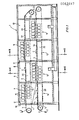
- FIGS. 1 to 3 A first embodiment of the hot air drying device suitable for carrying out the method according to the invention will first be explained with reference to FIGS. 1 to 3.
- Textile material 3 to be dried is transported through the hot air drying device 1 in the direction of the arrow 2 (ie in the longitudinal direction through the device 1).
- two transport belts space above one another (upper transport belt 4 and lower transport belt 5) are provided in this exemplary embodiment, on the upper run 4a or 5a of which the textile goods 3 to be treated are placed loosely.
- the top and the lower conveyor belt 4, 5 or their upper run 4a, 5a form two superimposed drying levels within the device housing 6, so that the textile material 3 passes through the device housing 6 twice during its drying treatment and thus the textile material inlet and the textile goods outlet are arranged on the same end face 1a of the device 1; in the example of Figure 1, the textile material 3 first runs in the upper drying level (on the conveyor belt 4) in the longitudinal direction through the housing 6, is then placed on the lower conveyor belt 5 forming the lower drying level and then runs back to the front side 1a, where it can then be removed or removed in another suitable manner.
- the device 1 or its housing 6 is divided in the longitudinal direction into a plurality of drying zones, and in this exemplary embodiment four drying zones 7, 8, 9, 10 and 11, 12, 13, 14 are provided on each floor, which in the order in accordance with the arrows 2 of the textile material 3 are passed through in succession.
- the drying zones 7 to 14 can be divided into two types with different air supply, namely in the drying zones 7, 9, 11, 13 hot air in the form of a convection flow with at least one side of the loosely guided textile material 3, preferably (in the example the Fig.
- the drying zones 7, 9, 11, 13 are shown as inflation drying zones and the drying zones 8, 10, 12, 14 as suction drying zones due to the air routing types.
- the inflation drying zones 7, 9, 11, 13 and the suction drying zones 8, 10, 12, 14 alternate in the transport direction (arrows 2) of the textile material 3 or in the longitudinal direction of the device 1, so that the textile material 3 is alternately subjected to convection drying and suction drying with hot air.
- the hot air is in each case blown onto the upper and lower side of the textile material 3 in such a way that it can also be removed again on the same side of the perforated carrier, that is to say of the conveyor belt 4 or 5.
- two drying zones with different hot air feeds that is, one inflation drying zone and one suction drying zone
- two drying zones with different hot air feeds that is, one inflation drying zone and one suction drying zone
- Each inflation drying zone 7, 9, 11, 13 is constructed essentially in the same way and has a group of nozzle boxes that can be acted upon by hot air and extend over the entire width of the textile material (upper and below the upper strand 4a, 5a of the conveyor belt 4, 5 carrying the textile material 3 Nozzle boxes 15 and lower nozzle boxes 16).
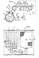
- These nozzle boxes 15, 16 are - cf. 2 and 3 - connected to the pressure side 17a of a circulating air fan 17 which generates the hot air flow, such a fan 17 being associated with each drying section.
- a suitable heat exchanger 18 In front of the suction side 17b or the pressure side 17a of each fan there is also a suitable heat exchanger 18 (FIG. 2) or 19 (Fig.3) arranged to heat the hot air stream (recirculating air stream); the other auxiliary devices usually present (for example for temperature control or the like) are not illustrated in more detail.
- the suction drying zones 8, 10, 12, 14 are also of essentially the same design.
- a vacuum box 20 is arranged under the upper run 4a or 5a of the associated conveyor belt 4, 5, which vacuum box extends over the entire width of the textile goods and has, for example, a perforated upper side 20a which presses against the textile goods 3 or the corresponding conveyor belt run 4a or 5a points. It is particularly important that in each drying section the vacuum box 20 is connected to the suction side 17b of the single circulating air fan 17 present there. In this way, in each drying section (7 and 14, 8 and 13, 9 and 12, 10 and 11) for the inflation drying zone and for the suction drying. zone, a single, common air circulation fan is required.
- the hot air drying device can generally consist of only two drying zones of different hot air supply (i.e. an inflation drying zone and a suction drying zone), these two drying zones then forming a single drying section in the manner described above.
- any number of drying sections of the type mentioned are connected in series and form the hot air drying device.
- the nozzle boxes 15 and 16 of the upper and lower rows in each inflation drying zone are provided with hot air outlet slots and can be arranged opposite one another in such a way that the textile material 3 lying loosely on the conveyor belts 4, 5 can be kept in a loose, wavy state (see Fig. 1).
- a second exemplary embodiment of a hot air drying device suitable for carrying out the method will be described with reference to the very schematic representation in FIG. While in the first exemplary embodiment according to FIGS. 1 to 3, the drying zones successive in the longitudinal direction of the device 1 in each drying level different hot air supply are provided with a common, continuous perforated conveyor belt as a carrier for the textile goods, each drying zone has a separate perforated carrier in the exemplary embodiment in FIG.
- the textile material 23 to be dried passes through at least two drying zones 25, 26 of different hot air supply in the direction of arrow 24 in succession.
- the drying zone first run through by the textile material 23 is designed as a suction drying zone 25 and the subsequent drying zone is designed as an inflation drying zone 26.
- the suction drying zone 25 is essentially formed by a suction drum 27 which can be designed in a manner known per se and whose perforated jacket forms the perforated carrier for the textile material 23.
- a desired wrapping of the drum jacket 27a from the textile material 23 can be achieved by deflecting rollers 28, 29; in the example in FIG. 4, the largest part of the circumference of the jacket is wrapped in the textile material 23 in order to achieve the most intensive possible suction of hot air (dashed arrows 30).
- the inflation drying zone 26 can in principle be designed in the same way as the inflation zones in the first exemplary embodiment (FIGS. 1 to 3).
- a perforated carrier for the textile material 23 a perforated carrier belt or conveyor belt 31 is provided, which is essentially formed only according to the length of this inflation drying zone 26 and loosely receives the textile material 23.
- the two drying zones 25 and 26 can also be successively passed through by the same hot air stream, they are also combined here to form a drying section by the suction drum 27 forming the suction drying zone 25 on the suction side and the upper and lower groups of the nozzle boxes 32, 33 in the inflation drying zone 26 are connected to the pressure side of a common circulating air fan 34, a heat exchanger 35 also being provided on the suction side of this fan 34, which ensures the heating of the hot air flow.
- a supply 36 for fresh air and a discharge 37 for used circulating air can also be provided here.
- the third exemplary embodiment in FIG. 5 also shows a modification of the embodiment shown in FIG. 1 in a very simplified representation (with the omission of a continuous perforated carrier tape provided here and with the textile material being omitted). Therefore, parts that are essentially identical in construction to the device parts of FIG. 1 are also used in FIG. 5 with the same reference numerals as in FIG. 1, but with the addition of a dash.
- each drying section is separated by two drying zones 7 'and 8' which are adjacent to one another or which are directly consecutive in the direction of textile transport (2 ') formed, of which the first drying zone as an inflation drying zone 7 'and the second drying zone as a suction drying zone 8' - each in the manner described (Fig.1).
- the drying zones 7 'and 8' lying in the housing 6 'of the hot air drying device 1', which form a common drying section, are connected to a common circulating air fan 40, the suction side 40a of which is preceded by a corresponding heat exchanger 41 for generating the hot air flow.
- the vacuum box 20 'of the suction drying zone 8' is also connected to the suction side 40a of the air circulation fan 40 via a pipeline 42, while the nozzle boxes 15 'and 16' (upper and lower nozzle boxes), which are combined in groups, are connected to the pressure side 40b of the air circulation fan 40 .
- the circulating air fans in all of the above-described exemplary embodiments, it should also be said that they can be arranged alternately in the longitudinal direction of the hot air drying device on one and the other longitudinal side of the housing, in order thereby to achieve particularly uniform drying over the length of the device.
- any other suitable heating device can also be used, e.g. a corresponding gas or oil burner, as is generally known in drying devices for textile goods.
Landscapes
- Engineering & Computer Science (AREA)
- Textile Engineering (AREA)
- Mechanical Engineering (AREA)
- General Engineering & Computer Science (AREA)
- Treatment Of Fiber Materials (AREA)
- Drying Of Solid Materials (AREA)
Applications Claiming Priority (2)
| Application Number | Priority Date | Filing Date | Title |
|---|---|---|---|
| DE3116836 | 1981-04-28 | ||
| DE19813116836 DE3116836A1 (de) | 1981-04-28 | 1981-04-28 | Verfahren und vorrichtung zur heissluft-trocknung von textilgut |
Publications (2)
| Publication Number | Publication Date |
|---|---|
| EP0063647A1 true EP0063647A1 (fr) | 1982-11-03 |
| EP0063647B1 EP0063647B1 (fr) | 1984-04-11 |
Family
ID=6130992
Family Applications (1)
| Application Number | Title | Priority Date | Filing Date |
|---|---|---|---|
| EP81110700A Expired EP0063647B1 (fr) | 1981-04-28 | 1981-12-22 | Dispositif pour le séchage par air chaud de matières textiles |
Country Status (2)
| Country | Link |
|---|---|
| EP (1) | EP0063647B1 (fr) |
| DE (2) | DE3116836A1 (fr) |
Cited By (5)
| Publication number | Priority date | Publication date | Assignee | Title |
|---|---|---|---|---|
| FR2545852A1 (fr) * | 1983-05-09 | 1984-11-16 | Brueckner Trockentechnik Gmbh | Dispositif de traitement a l'air chaud de produit textile en transport continu |
| WO2009081373A2 (fr) * | 2007-12-21 | 2009-07-02 | Imas S.P.A. | Procédé et appareil pour sécher des produits de granulométrie variable, des copeaux et des granulés |
| CN109425204A (zh) * | 2017-09-04 | 2019-03-05 | 江苏邦琳纺织有限公司 | 一种纺织用烘干箱 |
| CN113639541A (zh) * | 2021-08-23 | 2021-11-12 | 张玉成 | 一种碳纤维材料生产用干燥方法 |
| CN115772759A (zh) * | 2022-12-05 | 2023-03-10 | 辽宁新洪源环保材料有限公司 | 一种织物烘干房、纵向阶梯式织物整理装置及织物整理方法 |
Families Citing this family (1)
| Publication number | Priority date | Publication date | Assignee | Title |
|---|---|---|---|---|
| CN103123209B (zh) * | 2013-03-15 | 2014-12-03 | 东兴市怡诚食品开发有限公司 | 双门热风循环烘箱 |
Citations (4)
| Publication number | Priority date | Publication date | Assignee | Title |
|---|---|---|---|---|
| GB884324A (en) * | 1959-10-15 | 1961-12-13 | Samcoe Holding Corp | Drum dryer |
| CH408845A (de) * | 1963-02-12 | 1966-03-15 | Establishment For Automation | Vorrichtung zum Trocknen von losem Textilgut |
| DE2011567A1 (de) * | 1969-03-13 | 1970-09-17 | K.K. Ichikin Kogyosha, Kusatsu, Shiga (Japan) | Wärmebehandlungsvorrichtung für Stoffe |
| DE2301938A1 (de) * | 1973-01-16 | 1974-07-25 | Brueckner Apparatebau Gmbh | Verfahren und vorrichtung zur heisslufttrocknung einer nassbehandelten warenbahn |
Family Cites Families (3)
| Publication number | Priority date | Publication date | Assignee | Title |
|---|---|---|---|---|
| DE1951625A1 (de) * | 1969-10-14 | 1971-04-29 | Friedrich Haas Gmbh & Co Masch | Trockner fuer Gutsbahnen,vorzugsweise Trikotagen |
| DE2130464C3 (de) * | 1971-06-19 | 1981-01-29 | Vepa Ag, Riehen B. Basel (Schweiz) | Siebbandvorrichtung |
| DE2935373C2 (de) * | 1979-09-01 | 1985-08-08 | Lindauer Dornier Gmbh, 8990 Lindau | Vorrichtung zur Wärmebehandlung von flachen, auf gasdurchlässigen Transportbändern aufliegenden Warenbahnen |
-
1981
- 1981-04-28 DE DE19813116836 patent/DE3116836A1/de not_active Withdrawn
- 1981-12-22 DE DE8181110700T patent/DE3163113D1/de not_active Expired
- 1981-12-22 EP EP81110700A patent/EP0063647B1/fr not_active Expired
Patent Citations (4)
| Publication number | Priority date | Publication date | Assignee | Title |
|---|---|---|---|---|
| GB884324A (en) * | 1959-10-15 | 1961-12-13 | Samcoe Holding Corp | Drum dryer |
| CH408845A (de) * | 1963-02-12 | 1966-03-15 | Establishment For Automation | Vorrichtung zum Trocknen von losem Textilgut |
| DE2011567A1 (de) * | 1969-03-13 | 1970-09-17 | K.K. Ichikin Kogyosha, Kusatsu, Shiga (Japan) | Wärmebehandlungsvorrichtung für Stoffe |
| DE2301938A1 (de) * | 1973-01-16 | 1974-07-25 | Brueckner Apparatebau Gmbh | Verfahren und vorrichtung zur heisslufttrocknung einer nassbehandelten warenbahn |
Cited By (6)
| Publication number | Priority date | Publication date | Assignee | Title |
|---|---|---|---|---|
| FR2545852A1 (fr) * | 1983-05-09 | 1984-11-16 | Brueckner Trockentechnik Gmbh | Dispositif de traitement a l'air chaud de produit textile en transport continu |
| WO2009081373A2 (fr) * | 2007-12-21 | 2009-07-02 | Imas S.P.A. | Procédé et appareil pour sécher des produits de granulométrie variable, des copeaux et des granulés |
| WO2009081373A3 (fr) * | 2007-12-21 | 2009-11-26 | Imas S.P.A. | Procédé et appareil pour sécher des produits de granulométrie variable, des copeaux et des granulés |
| CN109425204A (zh) * | 2017-09-04 | 2019-03-05 | 江苏邦琳纺织有限公司 | 一种纺织用烘干箱 |
| CN113639541A (zh) * | 2021-08-23 | 2021-11-12 | 张玉成 | 一种碳纤维材料生产用干燥方法 |
| CN115772759A (zh) * | 2022-12-05 | 2023-03-10 | 辽宁新洪源环保材料有限公司 | 一种织物烘干房、纵向阶梯式织物整理装置及织物整理方法 |
Also Published As
| Publication number | Publication date |
|---|---|
| DE3116836A1 (de) | 1982-11-11 |
| DE3163113D1 (en) | 1984-05-17 |
| EP0063647B1 (fr) | 1984-04-11 |
Similar Documents
| Publication | Publication Date | Title |
|---|---|---|
| DE3026176C2 (de) | Tunnelofen für die Herstellung von beidseitig mit einem aushärtbaren Material beschichteten plattenartigen Flächengebilden, insbesondere Printplatten | |
| EP0063647A1 (fr) | Dispositif pour le séchage par air chaud de matières textiles | |
| EP0319681B1 (fr) | Dispositif pour le traitement thermique d'une large bande de textile en déplacement continu | |
| DE2032326B2 (de) | Vorrichtung zum kontinuierlichen und gleichförmigen Erhitzen und Kühlen eines angehäuften Kunstfaser-Spinnkabels | |
| EP0063642B1 (fr) | Dispositif pour le séchage par air chaud de matières textiles | |
| EP2092258B1 (fr) | Procédé de séchage de bois assemblé sous forme de piles | |
| DE3202923C2 (fr) | ||
| DE2248808A1 (de) | Vorrichtung zur falschdrall-texturierung und nachfixierung von aus thermoplastischem synthetischem material bestehenden garnen in kontinuierlicher arbeitsweise | |
| DE2056190C3 (de) | Düsentrockner für kontinuierlich durchlaufendes, bahnförmiges Material | |
| DE3202922A1 (de) | Vorrichtung zum trocknen einer laufenden fadenschar | |
| DE1660415B2 (de) | Vorrichtung zur Wärmebehandlung einer Vielzahl von synthetischen Garnen | |
| DE1962089C2 (de) | Mehrfachtogiefianlage | |
| EP0571322B1 (fr) | Dispositif pour le frisage continu des fils thermoplastiques | |
| DE2163285A1 (de) | Vorrichtung zur kontinuierlichen Trocknung und Appretur von Flächenbandmaterialien, insbesondere Textilien | |
| DE3112987C2 (de) | Vorrichtung zum Erwärmen einem kontinuierlich durchlaufenden Materialstranges | |
| DE4028907B4 (de) | Ofen für die kontinuierliche Trocknung von mindestens einem Textilfaden | |
| DE8111908U1 (de) | Vorrichtung zur heissluft-trocknung einer warenbahn | |
| DE7717141U1 (de) | Vorrichtung zur waermebehandlung, insbesondere zum trocknen und/oder fixieren, von kontinuierlich transportierten textilen warenbahnen | |
| DE2449335A1 (de) | Maschine fuer die behandlung eines fadens oder fadenbuendels durch falschdrallen | |
| DE19516127A1 (de) | Behandlungskammer zum kontinuierlichen Wärmebehandeln von Garnen | |
| DE1604953C (de) | Vorrichtung zum Trocknen von Gut in Klimatrocknern bzw. -trocknungsanlagen | |
| DE102021102262A1 (de) | Vorwärmkammer zum Vorwärmen einer textilen Warenbahn mittels Luft, Trockenanordnung sowie Verwendung einer solchen in einer Maschine zur Herstellung oder Bearbeitung einer textilen Warenbahn | |
| DE19803676A1 (de) | Vorrichtung zur Wärmebehandlung einer textilen Warenbahn | |
| WO2006087149A1 (fr) | Dispositif pour guider et manipuler un cable de fibres | |
| AT256605B (de) | Umlenkeinrichtung für bahnförmiges Material |
Legal Events
| Date | Code | Title | Description |
|---|---|---|---|
| PUAI | Public reference made under article 153(3) epc to a published international application that has entered the european phase |
Free format text: ORIGINAL CODE: 0009012 |
|
| AK | Designated contracting states |
Designated state(s): DE FR GB IT |
|
| 17P | Request for examination filed |
Effective date: 19821113 |
|
| ITF | It: translation for a ep patent filed |
Owner name: ING. FERRAROTTI GIOVANNI |
|
| GRAA | (expected) grant |
Free format text: ORIGINAL CODE: 0009210 |
|
| AK | Designated contracting states |
Designated state(s): DE FR GB IT |
|
| REF | Corresponds to: |
Ref document number: 3163113 Country of ref document: DE Date of ref document: 19840517 |
|
| ET | Fr: translation filed | ||
| PLBE | No opposition filed within time limit |
Free format text: ORIGINAL CODE: 0009261 |
|
| STAA | Information on the status of an ep patent application or granted ep patent |
Free format text: STATUS: NO OPPOSITION FILED WITHIN TIME LIMIT |
|
| 26N | No opposition filed | ||
| ITTA | It: last paid annual fee | ||
| PGFP | Annual fee paid to national office [announced via postgrant information from national office to epo] |
Ref country code: FR Payment date: 19981110 Year of fee payment: 18 |
|
| PGFP | Annual fee paid to national office [announced via postgrant information from national office to epo] |
Ref country code: GB Payment date: 19981124 Year of fee payment: 18 |
|
| PGFP | Annual fee paid to national office [announced via postgrant information from national office to epo] |
Ref country code: DE Payment date: 19990226 Year of fee payment: 18 |
|
| PG25 | Lapsed in a contracting state [announced via postgrant information from national office to epo] |
Ref country code: GB Free format text: LAPSE BECAUSE OF NON-PAYMENT OF DUE FEES Effective date: 19991222 |
|
| GBPC | Gb: european patent ceased through non-payment of renewal fee |
Effective date: 19991222 |
|
| PG25 | Lapsed in a contracting state [announced via postgrant information from national office to epo] |
Ref country code: FR Free format text: LAPSE BECAUSE OF NON-PAYMENT OF DUE FEES Effective date: 20000831 |
|
| PG25 | Lapsed in a contracting state [announced via postgrant information from national office to epo] |
Ref country code: DE Free format text: LAPSE BECAUSE OF NON-PAYMENT OF DUE FEES Effective date: 20001003 |
|
| REG | Reference to a national code |
Ref country code: FR Ref legal event code: ST |