EP0049323A1 - Bodenbelag für Fahrbahnen - Google Patents
Bodenbelag für Fahrbahnen Download PDFInfo
- Publication number
- EP0049323A1 EP0049323A1 EP81104486A EP81104486A EP0049323A1 EP 0049323 A1 EP0049323 A1 EP 0049323A1 EP 81104486 A EP81104486 A EP 81104486A EP 81104486 A EP81104486 A EP 81104486A EP 0049323 A1 EP0049323 A1 EP 0049323A1
- Authority
- EP
- European Patent Office
- Prior art keywords
- webs
- floor covering
- sections
- covering according
- edge
- Prior art date
- Legal status (The legal status is an assumption and is not a legal conclusion. Google has not performed a legal analysis and makes no representation as to the accuracy of the status listed.)
- Granted
Links
- 239000011324 bead Substances 0.000 claims abstract description 12
- 239000002184 metal Substances 0.000 claims abstract description 10
- 239000002689 soil Substances 0.000 claims abstract description 4
- 238000005452 bending Methods 0.000 claims description 5
- 238000005520 cutting process Methods 0.000 claims description 3
- 238000009408 flooring Methods 0.000 claims 1
- 210000002105 tongue Anatomy 0.000 description 4
- 238000003466 welding Methods 0.000 description 4
- 238000004519 manufacturing process Methods 0.000 description 2
- 238000000034 method Methods 0.000 description 2
- 238000004080 punching Methods 0.000 description 2
- 238000005096 rolling process Methods 0.000 description 1
- 230000003068 static effect Effects 0.000 description 1
- 239000000758 substrate Substances 0.000 description 1
Images

Classifications
-
- E—FIXED CONSTRUCTIONS
- E01—CONSTRUCTION OF ROADS, RAILWAYS, OR BRIDGES
- E01C—CONSTRUCTION OF, OR SURFACES FOR, ROADS, SPORTS GROUNDS, OR THE LIKE; MACHINES OR AUXILIARY TOOLS FOR CONSTRUCTION OR REPAIR
- E01C5/00—Pavings made of prefabricated single units
- E01C5/005—Individual couplings or spacer elements for joining the prefabricated units
-
- E—FIXED CONSTRUCTIONS
- E01—CONSTRUCTION OF ROADS, RAILWAYS, OR BRIDGES
- E01C—CONSTRUCTION OF, OR SURFACES FOR, ROADS, SPORTS GROUNDS, OR THE LIKE; MACHINES OR AUXILIARY TOOLS FOR CONSTRUCTION OR REPAIR
- E01C9/00—Special pavings; Pavings for special parts of roads or airfields
- E01C9/08—Temporary pavings
- E01C9/083—Temporary pavings made of metal, e.g. plates, network
-
- Y—GENERAL TAGGING OF NEW TECHNOLOGICAL DEVELOPMENTS; GENERAL TAGGING OF CROSS-SECTIONAL TECHNOLOGIES SPANNING OVER SEVERAL SECTIONS OF THE IPC; TECHNICAL SUBJECTS COVERED BY FORMER USPC CROSS-REFERENCE ART COLLECTIONS [XRACs] AND DIGESTS
- Y10—TECHNICAL SUBJECTS COVERED BY FORMER USPC
- Y10S—TECHNICAL SUBJECTS COVERED BY FORMER USPC CROSS-REFERENCE ART COLLECTIONS [XRACs] AND DIGESTS
- Y10S24/00—Buckles, buttons, clasps
- Y10S24/30—Separable-fastener or required component thereof
- Y10S24/31—Separable-fastener or required component thereof with third, detached member completing interlock
- Y10S24/33—Third member includes independently engaged hooks for linking spaced cavities
-
- Y—GENERAL TAGGING OF NEW TECHNOLOGICAL DEVELOPMENTS; GENERAL TAGGING OF CROSS-SECTIONAL TECHNOLOGIES SPANNING OVER SEVERAL SECTIONS OF THE IPC; TECHNICAL SUBJECTS COVERED BY FORMER USPC CROSS-REFERENCE ART COLLECTIONS [XRACs] AND DIGESTS
- Y10—TECHNICAL SUBJECTS COVERED BY FORMER USPC
- Y10S—TECHNICAL SUBJECTS COVERED BY FORMER USPC CROSS-REFERENCE ART COLLECTIONS [XRACs] AND DIGESTS
- Y10S403/00—Joints and connections
- Y10S403/15—Splice plates for co-linear members
-
- Y—GENERAL TAGGING OF NEW TECHNOLOGICAL DEVELOPMENTS; GENERAL TAGGING OF CROSS-SECTIONAL TECHNOLOGIES SPANNING OVER SEVERAL SECTIONS OF THE IPC; TECHNICAL SUBJECTS COVERED BY FORMER USPC CROSS-REFERENCE ART COLLECTIONS [XRACs] AND DIGESTS
- Y10—TECHNICAL SUBJECTS COVERED BY FORMER USPC
- Y10T—TECHNICAL SUBJECTS COVERED BY FORMER US CLASSIFICATION
- Y10T24/00—Buckles, buttons, clasps, etc.
- Y10T24/45—Separable-fastener or required component thereof [e.g., projection and cavity to complete interlock]
- Y10T24/45005—Separable-fastener or required component thereof [e.g., projection and cavity to complete interlock] with third detached member completing interlock [e.g., hook type]
-
- Y—GENERAL TAGGING OF NEW TECHNOLOGICAL DEVELOPMENTS; GENERAL TAGGING OF CROSS-SECTIONAL TECHNOLOGIES SPANNING OVER SEVERAL SECTIONS OF THE IPC; TECHNICAL SUBJECTS COVERED BY FORMER USPC CROSS-REFERENCE ART COLLECTIONS [XRACs] AND DIGESTS
- Y10—TECHNICAL SUBJECTS COVERED BY FORMER USPC
- Y10T—TECHNICAL SUBJECTS COVERED BY FORMER US CLASSIFICATION
- Y10T403/00—Joints and connections
- Y10T403/71—Rod side to plate or side
- Y10T403/7123—Traversed by connector
Definitions
- the invention relates to a floor covering for roadways, in particular for runways, consisting of detachably connected pieces of metal, which is provided on its underside with longitudinal webs engaging in the pre-consolidated soil.
- the longitudinal webs are welded to the underside of the covering plates (DE-AS 23 45 457). This requires considerable effort because the welding must be carried out very carefully. On the one hand, the weld must be sufficiently stable so that the webs do not break off; on the other hand, the lining plate must not warp during welding. In addition, the webs must first be brought into a predetermined position and held in this position during the welding process.
- the invention has for its object to simplify the manufacture of a floor covering of the type mentioned.
- the solution to the problem is primarily that the outer webs through the angled lateral edges of the sections and the inner Bridges are formed by downward-facing compressed beads.
- the webs are formed in a single operation, since only bending operations have to be carried out.
- the inventive design of the sections of the floor covering ensures that the predetermined distances between the webs are exactly maintained. Since the webs are components of the sections of the floor covering, they cannot break off even if the sections or the floor covering are handled improperly, as occurs with welded-on webs.
- further webs are provided on the underside of the sections, which form an angle with the longitudinal webs. This angle can be 90 ° or less.
- the other webs must be welded to the sections, as in the known floor covering. However, since it is sufficient to simply weld the further webs to the longitudinal webs, the sections cannot warp.
- the attachment of the further webs is further facilitated by the fact that the further webs extend over the clear width existing between the outer longitudinal webs of a section and are provided in the areas of the inner longitudinal webs with punched-open openings, the shape of which is the shape of the inner longitudinal webs is adapted. This also prevents the beads forming the longitudinal webs from opening, so that a further welding process on the longitudinal webs in the longitudinal direction is eliminated.
- the sections at a certain distance from each of their edges at least one recess for inserting a connecting clip or an edge piece, wherein the recesses are expediently designed as elongated holes running parallel to the relevant edge of the section.
- Such recesses can be produced, for example, by punching out.
- the assembly of the floor covering is also very simple in that the connecting clip is formed from a metal band, one end of which is bent in a hook shape and the other end of which is angled, the angled end having an inwardly directed bead.
- the connecting clip is formed from a metal band, one end of which is bent in a hook shape and the other end of which is angled, the angled end having an inwardly directed bead.
- the inwardly directed bead causes the connecting clip to be resiliently clamped so that it cannot be released without mechanical intervention.
- the connecting bracket is driven in, its angled end engages in the pre-consolidated soil and braces there in such a way that the connecting bracket does not come loose when the floor covering is loaded. Because of its simple design, the connecting clip can be produced in a single operation.
- the edge piece which may be required, is formed from a metal strip with a downward, longitudinally compressed bead and has at least one on its side facing a section by cutting the edge at at least two closely spaced locations and bending the between the Interfaces located part of the edge formed tongue and is provided on the side facing away from the section with holes.
- the tongue is dimensioned and arranged such that it can be inserted into one of the recesses in the section.
- the holes are used to dowel the edge piece on the substrate.
- the edge piece can also be produced in a single operation, since only bending and punching operations have to be carried out.
- the floor covering according to the invention has the advantages that no unintentional loosening or moving of parts is possible and that the replacement of possibly damaged parts or edge pieces requires very little effort.
- the individual sections of the floor covering are less than 50 kg in weight and can be laid by hand with simple aids without heavy equipment; they ensure a level rolling surface.
- the static function is taken over by the pre-consolidated surface after shaking.
- a further advantage of the floor covering according to the invention with regard to the load-bearing capacity is given by the fact that the sections of the floor covering can also be laid offset.
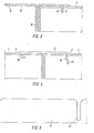
- the floor covering consists of sections 1, which are detachably connected to one another by means of connecting clips 2, and of edge pieces 3.
- the sections 1 are provided on their underside with longitudinal webs 4 and 5, the outer webs 4 being formed by the downwardly angled lateral edges of the sections 1 and the inner webs 5 by downward-pointing compressed beads. Furthermore, further, transverse webs 6 are provided on the underside of the sections 1. The transverse webs 6 can - as shown - run perpendicular to the ' longitudinal webs 4 and 5; but they can also form a different angle with the webs 4 and 5.
- the sections 1 have at a certain distance A vop each of their edges recesses 7, which are formed in the illustrated embodiment as parallel to the relevant edge of the section 1 elongated holes.
- the connecting clips 2 or the edge pieces 3 can be inserted into these recesses 7 (cf. FIGS. 3 and 4).
- the edge piece 3 shown consists of a metal strip which is provided with a downward, longitudinally compressed bead 8.
- the edge piece 3 On its side facing a section 1, the edge piece 3 has a plurality of tongues 9 which, by cutting the edge, each close to two mutually lying points and bending of the part of the edge located between the interfaces 10 are formed (cf. also FIG. 2).
- edge piece 3 On the side facing away from section 1, edge piece 3 is provided with bores 11.
- the tongues 9 are dimensioned and arranged such that they in the recesses? the sections 1 engage and thereby produce a releasable connection between the sections 1 and the edge piece 3.
- the connecting bracket 2 also consists of a metal band.
- One end 12 of the connecting clip 2 is bent in a hook shape, while the other end 13 is angled.
- the angled end 13 of the connecting bracket 2 is provided with an inwardly directed bead 14.
- the hook-shaped end 12 of the connecting clip 2 is first hooked into one of the recesses 7 of one of the sections 1. Then the angled end 13 of the connecting clip 2 is hammered into one of the recesses 7 of the other section 1.
- the transverse web 6 shown in FIG. 5 is provided with punched-open openings 15, the shape of which is adapted to the shape of the longitudinal webs 5 (see FIG. 1).
Landscapes
- Engineering & Computer Science (AREA)
- Architecture (AREA)
- Civil Engineering (AREA)
- Structural Engineering (AREA)
- Road Paving Structures (AREA)
Abstract
Description
- Die Erfindung betrifft einen aus lösbar miteinander verbundenen Teilstücken aus Metall bestehenden Bodenbelag für Fahrbahnen, insbesondere für Start- und Landebahnen, der an seiner Unterseite mit in den vorverfestigten Boden eingreifenden, längsverlaufenden Stegen versehen ist.
- Bei einem bekannten Bodenbelag der vorgenannten Art sind die längsverlaufenden Stege an der Unterseite der Belagplatten angeschweißt (DE-AS 23 45 457). Dies erfordert einen erheblichen Aufwand, weil das Schweißen sehr sorgfältig durchgeführt werden muß. Einerseits muß nämlich die Schweißung ausreichend stabil sein, damit die Stege nicht abbrechen; andererseits darf sich beim Schweißen die Belagplatte nicht verziehen. Darüber hinaus müssen die Stege zunächst in eine vorbestimmte Lage gebracht und während des Schweißvorgangs in dieser Lage gehalten werden.
- Der Erfindung liegt die Aufgabe zugrunde, die Herstellung eines Bodenbelages der eingangs genannten Art zu vereinfachen.
- Die Lösung der gestellten Aufgabe besteht in erster Linie darin, daß die äußeren Stege durch die abgewinkelten seitlichen Ränder der Teilstücke und die inneren Stege durch nach unten weisende zusammengedrückte Sicken gebildet sind. Die Bildung der Stege erfolgt in einem einzigen Arbeitsgang, da nur Biegevorgänge durchzuführen sind. Ferner ist durch die erfindungsgemäße Gestaltung der Teilstücke des Bodenbelages gewährleistet, daß die vorbestimmten Abstände der Stege voneinander genau eingehalten werden. Da die Stege Bestandteile der Teilstücke des Bodenbelages sind, können sie selbst bei unsachgemäßer Behandlung der Teilstücke bzw. des Bodenbelages nicht abbrechen, wie es bei angeschweißten Stegen vorkommt.
- In weiterer Ausgestaltung der Erfindung sind an der Unterseite der Teilstücke weitere Stege vorgesehen, die mit den längsverlaufenden Stegen einen Winkel bilden. Dieser Winkel kann 900 oder auch weniger betragen. Die weiteren Stege müssen zwar, wie bei dem bekannten Bodenbelag, an die Teilstücke angeschweißt werden. Da es aber ausreicht, die weiteren Stege lediglich mit den längsverlaufenden Stegen zu verschweißen, können sich hierbei die Teilstücke nicht verziehen.
- Das Anbringen der weiteren Stege wird ferner noch dadurch erleichtert, daß die weiteren Stege sich über die zwischen den äußeren längsverlaufenden Stegen eines Teilstückes vorhandene lichte Breite erstrecken und in den Bereichen der inneren längsverlaufenden Stege mit nach oben offenen Ausstanzungen versehen sind, deren Form der Form der inneren längsverlaufenden Stege angepaßt ist. Hierdurch wird außerdem das Aufgehen der die längsverlaufenden Stege bildenden Sicken verhindert, so daß ein weiterer Schweißvorgang an den längsverlaufenden Stegen in Längsrichtung entfällt.
- Um auch das Zusammensetzen des Bodenbelages in einfacher Weise durchführen zu können, weisen nach einem weiteren Merkmal der Erfindung die Teilstücke in einem bestimmten Abstand von jedem ihrer Ränder mindestens jeweils eine Ausnehmung zum Einsetzen einer Verbindungsklammer bzw. eines Randstückes auf, wobei die Ausnehmungen zweckmäßigerweise als parallel zu dem betreffenden Rand des Teilstücks verlaufende Langlöcher ausgebildet sind. Die Herstellung derartiger Ausnehmungen kann beispielsweise durch Ausstanzen erfolgen..
- Das Zusammensetzen des Bodenbelages ist ferner dadurch sehr einfach, daß die Verbindungsklammer aus einem Metallband gebildet ist, dessen eines Ende hakenförmig umgebogen und dessen anderes Ende abgewinkelt ist, wobei das abgewinkelte Ende eine nach innen gerichtete Sicke aufweist. Zur Verbindung von zwei Teilstücken des Bodenbelages wird lediglich das hakenförmige Ende der Verbindungsklammer in eine Ausnehmung eines der beiden Teistücke eingehängt, während das abgewinkelte Ende der Verbindungsklammer in eine Ausnehmung des anderen Teilstücks eingeschlagen wird. Die nach innen gerichtete Sicke bewirkt dabei ein federndes Festklemmen der Verbindungsklammer, so daß sich diese ohne mechanischen Eingriff nicht lösen kann. Ferner greift beim Einschlagen der Verbindungsklammer deren abgewinkeltes Ende in den vorverfestigten Boden ein und verspannt sich dort derart, daß sich die Verbindungsklammer bei Belastung des Bodenbelages nicht löst. Die Verbindungsklammer kann wegen ihrer einfachen Gestaltung in einem einzigen Arbeitsgang hergestellt werden.
- Das gegebenenfalls erforderliche Randstück ist aus einem Metallband mit einer nach unten weisenden, längsverlaufenden zusammengedrückten Sicke gebildet und weist an seiner einem Teilstück zugewandten Seite mindestens eine durch Einschneiden des Randes an mindestens zwei nahe beieinanderliegenden Stellen und Umbiegen des zwischen den Schnittstellen befindlichen Teils des Randes gebildete Zunge auf und ist auf der dem Teilstück abgewandten Seite mit Bohrungen versehen. Die Zunge ist dabei so bemessen und derart angeordnet, daß sie in eine der Ausnehmungen des Teilstückes eingesetzt werden kann. Die Bohrungen dienen dazu, das Randstück auf dem Untergrund zu verdübeln. Auch die Herstellung des Randstückes kann in einem einzigen Arbeitsgang erfolgen, da lediglich Biege- und Stanzvorgänge durchzuführen sind.
- Neben der leichten und einfachen Herstellbarkeit weist der erfindungsgemäße Bodenbelag die Vorteile auf, daß kein unbeabsichtigtes Lösen oder Verschieben von Teilen möglich ist und daß das Auswechseln gegebenenfalls beschädigter Teil- oder Randstücke nur einen sehr geringen Aufwand erfordert. Die einzelnen Teilstücke des Bodenbelages liegen im Gewicht unter 50 kg und sind ohne schweres Gerät von Hand mit einfachen Hilfsmitteln zu verlegen; sie gewährleisten eine ebene Rollfläche. Die statische Funktion wird nach dem Einrütteln vom vorverfestigten Untergrund übernommen.
- Ein weiterer Vorteil des erfindungsgemäßen Bodenbelages hinsichtlich der Belastbarkeit ist dadurch gegeben, daß die Teilstücke des Bodenbelages auch im Versatz verlegt werden können.
- Die Erfindung ist anhand der Zeichnung näher erläutert. Es zeigen:
- Fig. 1 einen Ausschnitt eines Bodenbelages in Vorderansicht,
- Fig. 2 eine Draufsicht auf den in Fig. 1 dargestellten Ausschnitt des Bodenbelages,
- Fig. 3 einen Schnitt nach der Linie III-III in Fig. 2, in größerem Maßstab,
- Fig. 4 einen Schnitt nach der Linie IV-IV in Fig. 2, ebenfalls in größerem Maßstab,
- Fig. 5 einen Abschnitt eines querverlaufenden Steges in Vorderansicht, in größerem Maßstab,
- Bei dem dargestellten Ausführungsbeispiel besteht der Bodenbelag aus Teilstücken 1, die mittels Verbindungsklammern 2 lösbar miteinander verbunden sind, sowie aus Randstücken 3.
- Die Teilstücke 1 sind an ihrer Unterseite mit längsverlaufenden Stegen 4 und 5 versehen, wobei die äußeren Stege 4 durch die nach unten abgewinkelten seitlichen Ränder der Teilstücke 1 und die inneren Stege 5 durch nach unten weisende zusammengedrückte Sicken gebildet sind. Ferner sind an der Unterseite der Teilstücke 1 weitere, quer verlaufende Stege 6 vorgesehen. Die querverlaufenden Stege 6 können - wie dargestellt - senkrecht zu den' längsverlaufenden Stegen 4 und 5 verlaufen; sie können aber auch einen anderen Winkel mit den Stegen 4 und 5 bilden.
- Die Teilstücke 1 weisen in einem bestimmten Abstand A vop jedem ihrer Ränder Ausnehmungen 7 auf, die bei dem dargestellten Ausführungsbeispiel als parallel zu dem betreffenden Rand des Teilstücks 1 verlaufende Langlöcher ausgebildet sind. In diese Ausnehmungen 7 können die Verbindungsklammern 2 bzw. die Randstücke 3 eingesetzt werden (vgl. Fig. 3 und 4).
- Aus Fig. 3 ist zu ersehen, daß das dargestellte Randstück 3 aus einem Metallband besteht, das mit einer nach unten weisenden, längsverlaufenden zusammengedrückten Sicke 8 versehen ist. An seiner einem Teilstück 1 zugewandten Seite weist das Randstück 3 mehrere Zungen 9 auf, die durch Einschneiden des Randes an jeweils zwei nahe beieinanderliegenden Stellen und Umbiegen des zwischen den Schnittstellen 10 befindlichen Teils des Randes gebildet sind (vgl. auch Fig. 2). Auf der dem Teilstück 1 abgewandten Seite ist das Randstück 3 mit Bohrungen 11 versehen. Die Zungen 9 sind so bemessen und derart angeordnet, daß sie in die Ausnehmungen ? der Teilstücke 1 eingreifen und dadurch zwischen den Teilstücken 1 und dem Randstück 3 eine lösbare Verbindung herstellen.
- Wie aus Fig. 4 zu ersehen ist, besteht die Verbindungsklammer 2 ebenfalls aus einem Metallband. Das eine Ende 12 der Verbindungsklammer 2 ist hakenförmig umgebogen, während das andere Ende 13 abgewinkelt ist. Das abgewinkelte Ende 13 der Verbindungsklammer 2 ist mit einer nach innen gerichteten Sicke 14 versehen. Um zwei Teilstücke 1 miteinander zu verbinden, wird zunächst das hakenförmige Ende 12 der Verbindungsklammer 2 in eine der Ausnehmungen 7 eines der Teilstücke 1 eingehängt. Sodann wird das abgewinkelte Ende 13 der Verbindungsklammer 2 in eine der Ausnehmungen 7 des anderen Teilstücks 1 eingeschlagen.
- Der in Fig. 5 dargestellte querverlaufende Steg 6 ist mit nach oben offenen Ausstanzungen 15 versehen, deren Form der Form der längsverlaufenden Stege 5 (vgl. Fig. 1) angepaßt ist.
Claims (7)
Applications Claiming Priority (2)
| Application Number | Priority Date | Filing Date | Title |
|---|---|---|---|
| DE3037809 | 1980-10-07 | ||
| DE19803037809 DE3037809A1 (de) | 1980-10-07 | 1980-10-07 | Bodenbelag fuer fahrbahnen |
Publications (2)
| Publication Number | Publication Date |
|---|---|
| EP0049323A1 true EP0049323A1 (de) | 1982-04-14 |
| EP0049323B1 EP0049323B1 (de) | 1984-02-22 |
Family
ID=6113792
Family Applications (1)
| Application Number | Title | Priority Date | Filing Date |
|---|---|---|---|
| EP81104486A Expired EP0049323B1 (de) | 1980-10-07 | 1981-06-11 | Bodenbelag für Fahrbahnen |
Country Status (3)
| Country | Link |
|---|---|
| US (1) | US4440363A (de) |
| EP (1) | EP0049323B1 (de) |
| DE (2) | DE3037809A1 (de) |
Cited By (6)
| Publication number | Priority date | Publication date | Assignee | Title |
|---|---|---|---|---|
| DE3236043A1 (de) * | 1982-09-29 | 1984-03-29 | Kaspar 8940 Memmingen Klaus | Befahrbare flaeche fuer mechanische parkeinrichtungen, rampen, hebebuehnen od. dgl. |
| EP0101599A3 (en) * | 1982-08-17 | 1985-04-17 | Hoesch Aktiengesellschaft | Locking element and pincers for freeing and for withdrawing the same |
| DE19528530A1 (de) * | 1995-08-03 | 1996-03-28 | Herbst Andreesen Jutta | Trittplatte aus Aluminium für Rasen- und Erdflächen, deren Oberfläche ein rutschfestes Profil aufweist |
| WO1997025480A1 (de) * | 1996-01-08 | 1997-07-17 | Knoebel Gerd Franz | Bodenbelag |
| WO2008091879A1 (en) * | 2007-01-24 | 2008-07-31 | Reynolds Consumer Products, Inc. | Portable porous pavement system and method for assembling such a pavement system |
| US8398046B2 (en) | 2007-01-24 | 2013-03-19 | Reynolds Presto Products, Inc. | Clamp device for portable porous pavement system |
Families Citing this family (11)
| Publication number | Priority date | Publication date | Assignee | Title |
|---|---|---|---|---|
| DE3329985A1 (de) * | 1983-08-19 | 1985-03-07 | Klöckner-Werke AG, 4100 Duisburg | Plattenfoermiges element fuer eine fahrstrasse |
| US4584806A (en) * | 1985-03-11 | 1986-04-29 | Graham Jr Andrew S | System for interconnecting panels |
| US4796392A (en) * | 1986-03-19 | 1989-01-10 | Graham Jr Andrew S | System for interconnecting panels of containers |
| US4745666A (en) * | 1987-07-17 | 1988-05-24 | Etco Building Systems, Inc. | Spring clip for sheet metal construction |
| USD304575S (en) | 1987-07-24 | 1989-11-14 | Charles Batzel | Support pad for a recreational vehicle jack or the like |
| US6996946B1 (en) * | 1999-02-26 | 2006-02-14 | Sergio Cazzolaro | Structures which can be dismantled and folded, consisting of interconnecting tubular elements |
| US7204064B2 (en) * | 2000-02-18 | 2007-04-17 | Sergio Cazzolaro | Structures which can be dismantled and folded, consisting of interconnecting tubular elements |
| NL1017348C1 (nl) | 2001-02-13 | 2002-08-14 | Stabag Pcp B V | Panelensysteem. |
| US7021009B2 (en) * | 2003-02-12 | 2006-04-04 | Bruce Johnson | Emergency housing |
| US7329068B2 (en) * | 2005-01-07 | 2008-02-12 | Universal Alloy Corporation | Grid locked stiffened panels with interlocking features |
| WO2025002550A1 (de) * | 2023-06-28 | 2025-01-02 | Haspel Raoul | Verbinder und verfahren zum verbinden einer ersten platte mit einer zweiten platte |
Citations (6)
| Publication number | Priority date | Publication date | Assignee | Title |
|---|---|---|---|---|
| US2294550A (en) * | 1940-09-24 | 1942-09-01 | Carnegie Illionis Steel Corp | Portable deck |
| AT244379B (de) * | 1962-08-04 | 1966-01-10 | Wuppermann Gmbh Theodor | Bodenbelag, vornehmlich zur Verwendung als Notstartbahn für Flugzeuge |
| DE1291762B (de) * | 1964-04-25 | 1969-04-03 | Luitpold Dr Ing | Fahrbahnbelag aus metallenen Bodenbelagplatten |
| DE1910213B2 (de) * | 1969-02-28 | 1973-03-01 | Domnick, Arno, 4451 Holthausen | Aus vorgefertigten teilen bestehende umsetzbare behelfsfahrbahn |
| DE2410331A1 (de) * | 1973-03-23 | 1974-09-26 | Mansfeld Kombinat W Pieck Veb | Transportable baustellen- und bauwegebefestigung |
| DE2737179A1 (de) * | 1977-08-18 | 1979-03-01 | Karl Ohrndorf | Bodenbelag aus metall fuer luftfahrzeug-rollbahnen oder andere verkehrswege |
Family Cites Families (5)
| Publication number | Priority date | Publication date | Assignee | Title |
|---|---|---|---|---|
| GB262845A (en) * | 1925-09-09 | 1926-12-09 | Albert Edward Miller | Improvements in or relating to guide strips or marks to facilitate traffic regulation on roads |
| US2898741A (en) * | 1950-05-09 | 1959-08-11 | Bowerston Shale Company | Spring clip for perforated pipes and the combination |
| US3023470A (en) * | 1957-10-11 | 1962-03-06 | Multifastener Spring Division | Screwless cable clip |
| CA972537A (en) * | 1973-03-07 | 1975-08-12 | Earl J. Cisler | Cabinet clip |
| US4062511A (en) * | 1975-09-03 | 1977-12-13 | Liskey Architectural Mfg. Inc. | Bracket |
-
1980
- 1980-10-07 DE DE19803037809 patent/DE3037809A1/de not_active Withdrawn
-
1981
- 1981-06-11 EP EP81104486A patent/EP0049323B1/de not_active Expired
- 1981-06-11 DE DE8181104486T patent/DE3162360D1/de not_active Expired
- 1981-10-01 US US06/307,592 patent/US4440363A/en not_active Expired - Fee Related
Patent Citations (6)
| Publication number | Priority date | Publication date | Assignee | Title |
|---|---|---|---|---|
| US2294550A (en) * | 1940-09-24 | 1942-09-01 | Carnegie Illionis Steel Corp | Portable deck |
| AT244379B (de) * | 1962-08-04 | 1966-01-10 | Wuppermann Gmbh Theodor | Bodenbelag, vornehmlich zur Verwendung als Notstartbahn für Flugzeuge |
| DE1291762B (de) * | 1964-04-25 | 1969-04-03 | Luitpold Dr Ing | Fahrbahnbelag aus metallenen Bodenbelagplatten |
| DE1910213B2 (de) * | 1969-02-28 | 1973-03-01 | Domnick, Arno, 4451 Holthausen | Aus vorgefertigten teilen bestehende umsetzbare behelfsfahrbahn |
| DE2410331A1 (de) * | 1973-03-23 | 1974-09-26 | Mansfeld Kombinat W Pieck Veb | Transportable baustellen- und bauwegebefestigung |
| DE2737179A1 (de) * | 1977-08-18 | 1979-03-01 | Karl Ohrndorf | Bodenbelag aus metall fuer luftfahrzeug-rollbahnen oder andere verkehrswege |
Cited By (7)
| Publication number | Priority date | Publication date | Assignee | Title |
|---|---|---|---|---|
| EP0101599A3 (en) * | 1982-08-17 | 1985-04-17 | Hoesch Aktiengesellschaft | Locking element and pincers for freeing and for withdrawing the same |
| DE3236043A1 (de) * | 1982-09-29 | 1984-03-29 | Kaspar 8940 Memmingen Klaus | Befahrbare flaeche fuer mechanische parkeinrichtungen, rampen, hebebuehnen od. dgl. |
| DE19528530A1 (de) * | 1995-08-03 | 1996-03-28 | Herbst Andreesen Jutta | Trittplatte aus Aluminium für Rasen- und Erdflächen, deren Oberfläche ein rutschfestes Profil aufweist |
| WO1997025480A1 (de) * | 1996-01-08 | 1997-07-17 | Knoebel Gerd Franz | Bodenbelag |
| WO2008091879A1 (en) * | 2007-01-24 | 2008-07-31 | Reynolds Consumer Products, Inc. | Portable porous pavement system and method for assembling such a pavement system |
| US7544010B2 (en) | 2007-01-24 | 2009-06-09 | Reynolds Consumer Products, Inc. | Portable porous pavement system and methods |
| US8398046B2 (en) | 2007-01-24 | 2013-03-19 | Reynolds Presto Products, Inc. | Clamp device for portable porous pavement system |
Also Published As
| Publication number | Publication date |
|---|---|
| DE3037809A1 (de) | 1982-05-06 |
| DE3162360D1 (en) | 1984-03-29 |
| EP0049323B1 (de) | 1984-02-22 |
| US4440363A (en) | 1984-04-03 |
Similar Documents
| Publication | Publication Date | Title |
|---|---|---|
| EP0049323B1 (de) | Bodenbelag für Fahrbahnen | |
| EP2208835B1 (de) | Paneel, insbesondere Fussbodenpaneel | |
| DE1295579B (de) | Vorrichtung zum UEberbruecken von Dehnungsfugen, insbesondere in Bruecken | |
| DE19623956C1 (de) | Als Blechformteil hergestellter Ausleger | |
| DE3139287A1 (de) | "verbindungsplatte" | |
| DE2720395A1 (de) | Pflug | |
| DE3024511A1 (de) | Schaltafel aus zwei sich zu einem rechteck ergaenzenden teilen | |
| DE202020103509U1 (de) | Vorrichtung zum Reinigen von Reifenlaufflächen | |
| DE4136898A1 (de) | Siebbelag | |
| DE19918824B4 (de) | Siebboden für eine Siebmaschine | |
| DE2950751A1 (de) | Winkeltraeger in geschweisster kastenbauweise | |
| EP0625438B1 (de) | Stegglied für Reifenkette | |
| DE3202468C2 (de) | Halterung für Zaunpfähle | |
| EP0116303B1 (de) | Als Gitterträger ausgebildeter Kalottenfussbalken | |
| EP0326676B1 (de) | Laufrostelement zum Verlegen auf unebenem Boden, insbesondere auf der Sohle von Grubenstrecken im untertägigen Bergbau | |
| EP0101599B1 (de) | Verriegelungselement und Zange zum Lösen und Entfernen des Verriegelungselementes | |
| DE2856180C2 (de) | Zerlegbare Brücke mit Unterspannung | |
| DE1708686C3 (de) | Haupttraeger fuer zerlegbare Bruecken | |
| DE202025100130U1 (de) | Rasenrakel | |
| DE1658524C3 (de) | Abdeckvorrichtung für Dehnungsfugen in Verkehrswegen, insbesondere von Straßenbrücken | |
| DE3218155A1 (de) | Verriegelungselement | |
| DE1634805C3 (de) | Klemmvorrichtung für eine verschiebbar an einem Aufnahmerahmen eines Schleppen heckseitig über einen Tragteil angeschlossene Tiefldffelbaggerausrustung | |
| DE3500977A1 (de) | Geruestelement, insbesondere konsole, mit ansatzstueck zum aufsetzen eines anderen elements, und mit einer bohrung zum einsetzen eines stifts durch diese hindurch | |
| EP0625437A1 (de) | Stegglied für Reifenkette | |
| DE2737179A1 (de) | Bodenbelag aus metall fuer luftfahrzeug-rollbahnen oder andere verkehrswege |
Legal Events
| Date | Code | Title | Description |
|---|---|---|---|
| PUAI | Public reference made under article 153(3) epc to a published international application that has entered the european phase |
Free format text: ORIGINAL CODE: 0009012 |
|
| AK | Designated contracting states |
Designated state(s): BE DE FR GB IT LU NL |
|
| 17P | Request for examination filed |
Effective date: 19820306 |
|
| RBV | Designated contracting states (corrected) |
Designated state(s): BE DE FR GB IT LU NL |
|
| ITCL | It: translation for ep claims filed |
Representative=s name: STUDIO JAUMANN |
|
| TCNL | Nl: translation of patent claims filed | ||
| RBV | Designated contracting states (corrected) |
Designated state(s): BE DE FR GB IT LU NL |
|
| RAP1 | Party data changed (applicant data changed or rights of an application transferred) |
Owner name: HOESCH WERKE AKTIENGESELLSCHAFT |
|
| ITF | It: translation for a ep patent filed | ||
| GRAA | (expected) grant |
Free format text: ORIGINAL CODE: 0009210 |
|
| AK | Designated contracting states |
Designated state(s): BE DE FR GB IT LU NL |
|
| ET | Fr: translation filed | ||
| REF | Corresponds to: |
Ref document number: 3162360 Country of ref document: DE Date of ref document: 19840329 |
|
| PGFP | Annual fee paid to national office [announced via postgrant information from national office to epo] |
Ref country code: FR Payment date: 19840515 Year of fee payment: 4 |
|
| PGFP | Annual fee paid to national office [announced via postgrant information from national office to epo] |
Ref country code: DE Payment date: 19840519 Year of fee payment: 4 |
|
| PG25 | Lapsed in a contracting state [announced via postgrant information from national office to epo] |
Ref country code: LU Free format text: LAPSE BECAUSE OF NON-PAYMENT OF DUE FEES Effective date: 19840630 |
|
| PGFP | Annual fee paid to national office [announced via postgrant information from national office to epo] |
Ref country code: BE Payment date: 19840630 Year of fee payment: 4 |
|
| RAP2 | Party data changed (patent owner data changed or rights of a patent transferred) |
Owner name: HOESCH AKTIENGESELLSCHAFT |
|
| PLBE | No opposition filed within time limit |
Free format text: ORIGINAL CODE: 0009261 |
|
| STAA | Information on the status of an ep patent application or granted ep patent |
Free format text: STATUS: NO OPPOSITION FILED WITHIN TIME LIMIT |
|
| BECN | Be: change of holder's name |
Effective date: 19840222 |
|
| 26N | No opposition filed | ||
| NLT2 | Nl: modifications (of names), taken from the european patent patent bulletin |
Owner name: HOESCH AKTIENGESELLSCHAFT TE DORTMUND, BONDSREPUBL |
|
| PGFP | Annual fee paid to national office [announced via postgrant information from national office to epo] |
Ref country code: NL Payment date: 19870630 Year of fee payment: 7 |
|
| PG25 | Lapsed in a contracting state [announced via postgrant information from national office to epo] |
Ref country code: GB Effective date: 19880611 |
|
| BERE | Be: lapsed |
Owner name: HOESCH A.G. Effective date: 19880630 |
|
| PG25 | Lapsed in a contracting state [announced via postgrant information from national office to epo] |
Ref country code: NL Effective date: 19890101 |
|
| NLV4 | Nl: lapsed or anulled due to non-payment of the annual fee | ||
| GBPC | Gb: european patent ceased through non-payment of renewal fee | ||
| PG25 | Lapsed in a contracting state [announced via postgrant information from national office to epo] |
Ref country code: FR Free format text: LAPSE BECAUSE OF NON-PAYMENT OF DUE FEES Effective date: 19890228 |
|
| PG25 | Lapsed in a contracting state [announced via postgrant information from national office to epo] |
Ref country code: DE Effective date: 19890301 |
|
| REG | Reference to a national code |
Ref country code: FR Ref legal event code: ST |
|
| PG25 | Lapsed in a contracting state [announced via postgrant information from national office to epo] |
Ref country code: BE Effective date: 19890630 |