EP0047861B1 - Farbwerk mit changierenden Farbauftragwalzen - Google Patents
Farbwerk mit changierenden Farbauftragwalzen Download PDFInfo
- Publication number
- EP0047861B1 EP0047861B1 EP81106269A EP81106269A EP0047861B1 EP 0047861 B1 EP0047861 B1 EP 0047861B1 EP 81106269 A EP81106269 A EP 81106269A EP 81106269 A EP81106269 A EP 81106269A EP 0047861 B1 EP0047861 B1 EP 0047861B1
- Authority
- EP
- European Patent Office
- Prior art keywords
- roller
- ink
- shaft
- rollers
- inking unit
- Prior art date
- Legal status (The legal status is an assumption and is not a legal conclusion. Google has not performed a legal analysis and makes no representation as to the accuracy of the status listed.)
- Expired
Links
- 238000007639 printing Methods 0.000 claims abstract description 14
- 238000007645 offset printing Methods 0.000 claims description 4
- 239000011248 coating agent Substances 0.000 description 2
- 238000000576 coating method Methods 0.000 description 2
- 238000004040 coloring Methods 0.000 description 2
- 230000000694 effects Effects 0.000 description 2
- 239000000463 material Substances 0.000 description 2
- 230000001360 synchronised effect Effects 0.000 description 2
- 241000287222 Drupa Species 0.000 description 1
- 230000003542 behavioural effect Effects 0.000 description 1
- 230000005540 biological transmission Effects 0.000 description 1
- 230000008878 coupling Effects 0.000 description 1
- 238000010168 coupling process Methods 0.000 description 1
- 238000005859 coupling reaction Methods 0.000 description 1
- 239000000839 emulsion Substances 0.000 description 1
- 238000009434 installation Methods 0.000 description 1
- 238000007761 roller coating Methods 0.000 description 1
- 239000002352 surface water Substances 0.000 description 1
- 238000001665 trituration Methods 0.000 description 1
- XLYOFNOQVPJJNP-UHFFFAOYSA-N water Substances O XLYOFNOQVPJJNP-UHFFFAOYSA-N 0.000 description 1
Images


Classifications
-
- B—PERFORMING OPERATIONS; TRANSPORTING
- B41—PRINTING; LINING MACHINES; TYPEWRITERS; STAMPS
- B41F—PRINTING MACHINES OR PRESSES
- B41F31/00—Inking arrangements or devices
- B41F31/15—Devices for moving vibrator-rollers
-
- Y—GENERAL TAGGING OF NEW TECHNOLOGICAL DEVELOPMENTS; GENERAL TAGGING OF CROSS-SECTIONAL TECHNOLOGIES SPANNING OVER SEVERAL SECTIONS OF THE IPC; TECHNICAL SUBJECTS COVERED BY FORMER USPC CROSS-REFERENCE ART COLLECTIONS [XRACs] AND DIGESTS
- Y10—TECHNICAL SUBJECTS COVERED BY FORMER USPC
- Y10S—TECHNICAL SUBJECTS COVERED BY FORMER USPC CROSS-REFERENCE ART COLLECTIONS [XRACs] AND DIGESTS
- Y10S101/00—Printing
- Y10S101/38—Means for axially reciprocating inking rollers
Definitions
- the invention relates to an inking unit for printing presses, in particular offset printing machines, in which the ink is metered from an ink reservoir to the inking rollers of the inking unit, individual rollers of this inking unit being in contact with the plate cylinder as changing ink transfer rollers, which are preceded by changing inking rollers.
- Inking units are generally based on the task of feeding the printing plate of an offset printing press a uniform, thin ink film. Depending on the type of printing form, however, these inking units can appear which have a negative impact on the print quality.
- an inking unit in which at least two distribution rollers are provided. However, these are assigned to another area of the inking unit and are practically driven at the same stroke frequency, the stroke movement of the one friction roller being superimposed only by a small oscillating oscillating movement which, seen over several periods of the stroke frequency, practically does not change the same.
- CH-A-603 359 also discloses a device for an oscillating friction roller, with which the stroke frequency can be changed with a constant stroke amplitude.
- Ink rubbing rollers are known from various writings: From DE-OS 1 611 196 z. B. a color distribution roller is known in which a gear is provided in the interior of the roller through which a relatively long stroke period can be achieved.
- the disadvantage of the device is, in particular, that due to the compact internal structure and the complex gear mechanism of the distribution roller, an inadmissibly high weight is created for easy and subsequent installation as an application roller. It should be noted that application rollers must be pivoted away.
- An embodiment of the distributor roller according to DE-OS 2 045 717 cannot be used for a distributor roller, as is to be used in the invention, since the space inside the tube body is cramped. Furthermore, in this embodiment of the applicator roll there is a stroke frequency which does not meet the prerequisite for the invention.
- the object of the invention is to improve a known inking unit by simple measures so that uniform inking of the printing cylinder is possible and faults z. B. are avoided by stenciling, the measures can also be applied to existing inking units if possible.
- the advantage of this device consists primarily in the fact that such a uniform ink film can be applied to the printing plate due to the differing stroke frequency between the friction roller and the application roller, so that perfect printing quality can be achieved as the printing result.
- Another advantage is that due to the special design of the inking rollers it is easy to retrofit existing inking units.
- the simple drive of the inking roller shaft allows the stroke frequency of the inking roller to be dimensioned in a very inexpensive manner in such a way that optimal printing results can be achieved.
- Another advantage with regard to the service life of the printing plate is that this is increased by the use of an application roller coating, as is customary in letterpress machines.
- control gear enables light a continuous adjustment of the stroke frequency of the distribution to different print jobs.
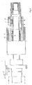
- the ink is metered from an ink reservoir 1 via an ink lifter 2 to a 1st friction roller 3.
- This 1st rubbing roller 3 is assigned a plurality of transfer rollers 4, which take over the ink transport.
- the ink passes through several transfer rollers 4 to further rubbing rollers 6 and 7.
- These rubbing rollers 6 and 7 are assigned inking rollers 8-11, which feed the ink to the plate cylinder 12 in finely divided form.
- the fourth inking roller 11 and at least one further inking roller 8-10 are designed as a rubbing roller.
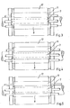
- the friction roller 11 shows in its sectional view a tubular body 13 which is provided with a coating 14.
- the tubular body 13 is freely rotating on the shaft 15.
- a drum curve 16 is fixedly connected to the shaft 15 at one end.
- a cam roller 18 engages in the cam track 17 of the drum cam 16 and sits on a roller bolt 19 fastened to the tubular body 13.
- the friction roller 11 is driven by the friction roller 7 by means of friction. With the shaft 15 at a standstill, the friction roller 11 would execute an oscillating movement in this case, in such a way that one stroke occurs per revolution of the friction roller 11.
- a gearwheel 20 is attached to the shaft 15 and firmly connected to the latter.
- This gear 20 meshes with a gear 21 attached to the grater 7 and sets the shaft 15 in rotation.
- a relative speed occurs between the casing body 13 and the shaft 15, by means of which the drum curve 16 lags behind the tubular body 13.
- the fact that tubular body 13 and drum curve 16 have the same direction of rotation reduces the relative speed between the tubular body 13 and shaft 15 and with the drum curve 16 so that, according to the translation of the gears 20 and 21, only a fraction of the stroke per friction roller revolution is present.
- the gear 21 on the grater 7 is designed as a divided gear which must be screwed onto the grater pin of the grater 7.
- the coating 14 of the tubular body 13 from a material which has the properties of the material commercially available under the name Febolith 01 33/30.
- the friction function of the application roller is switched off, this can be done quite simply by removing the roller bolt 19 together with the cam roller 18.
- the speed of the shaft can be increased so that the speed of the shaft 15 is equal to the speed of the tubular body 13 and thus synchronous movement of the cam roller 18 and drum cam 16 occurs, whereby the friction frequency becomes zero.
- Another possibility of switching off the friction movement of the applicator roller is achieved by arranging a clutch 22 between the gear 20, 21 and the shaft 15.
- the coupling 22 is to be designed in such a way that when the transmission 20, 21 is uncoupled, a relative rotation of the shaft 15 relative to the tubular body 13 and thus a traversing movement of the inking roller is not possible.
Landscapes
- Inking, Control Or Cleaning Of Printing Machines (AREA)
- Ink Jet (AREA)
Priority Applications (1)
| Application Number | Priority Date | Filing Date | Title |
|---|---|---|---|
| AT81106269T ATE10721T1 (de) | 1980-09-13 | 1981-08-12 | Farbwerk mit changierenden farbauftragwalzen. |
Applications Claiming Priority (2)
| Application Number | Priority Date | Filing Date | Title |
|---|---|---|---|
| DE3034644A DE3034644C2 (de) | 1980-09-13 | 1980-09-13 | Farbwerk mit changierenden Farbauftragswalzen |
| DE3034644 | 1980-09-13 |
Publications (2)
| Publication Number | Publication Date |
|---|---|
| EP0047861A1 EP0047861A1 (de) | 1982-03-24 |
| EP0047861B1 true EP0047861B1 (de) | 1984-12-12 |
Family
ID=6111902
Family Applications (1)
| Application Number | Title | Priority Date | Filing Date |
|---|---|---|---|
| EP81106269A Expired EP0047861B1 (de) | 1980-09-13 | 1981-08-12 | Farbwerk mit changierenden Farbauftragwalzen |
Country Status (6)
| Country | Link |
|---|---|
| US (1) | US4397236A (enExample) |
| EP (1) | EP0047861B1 (enExample) |
| JP (1) | JPS57117961A (enExample) |
| AT (1) | ATE10721T1 (enExample) |
| BR (1) | BR8104959A (enExample) |
| DE (2) | DE3034644C2 (enExample) |
Cited By (2)
| Publication number | Priority date | Publication date | Assignee | Title |
|---|---|---|---|---|
| DE102005030127A1 (de) * | 2005-06-28 | 2007-01-04 | Maschinenfabrik Wifag | Gegenläufige Farbreiber |
| DE102006035713B4 (de) * | 2006-08-01 | 2013-09-05 | manroland sheetfed GmbH | Farbwerksantrieb in einer Verarbeitungsmaschine |
Families Citing this family (33)
| Publication number | Priority date | Publication date | Assignee | Title |
|---|---|---|---|---|
| DE8330123U1 (de) * | 1983-10-19 | 1984-01-12 | Heidelberger Druckmaschinen Ag, 6900 Heidelberg | Farbwerk fuer druckmaschinen |
| US4493257A (en) * | 1983-10-25 | 1985-01-15 | Harris Graphics Corporation | Inker for a printing press |
| DE3342877C1 (de) * | 1983-11-26 | 1985-01-10 | M.A.N.- Roland Druckmaschinen AG, 6050 Offenbach | Heberfarbwerk fuer eine Rotationsdruckmaschine |
| DE3419764C2 (de) * | 1984-05-26 | 1986-05-28 | M.A.N.- Roland Druckmaschinen AG, 6050 Offenbach | Vorrichtung zum seitlichen Transportieren überschüssiger Farbe, Farb-/Wasseremulsion oder Wasser |
| DE3424721C2 (de) * | 1984-07-05 | 1986-12-18 | M.A.N.- Roland Druckmaschinen AG, 6050 Offenbach | Farbwerk für eine Druckmaschine |
| DE3519134C1 (de) * | 1985-05-29 | 1988-10-20 | Roland Man Druckmasch | Walze,insbesondere Farb- oder Verreiberwalze,fuer Druckmaschinen sowie deren Verwendung |
| JPS61274944A (ja) * | 1985-05-30 | 1986-12-05 | Toyo Tsusho:Kk | 印刷機 |
| JPS6225546U (enExample) * | 1985-07-30 | 1987-02-17 | ||
| US4887533A (en) * | 1986-05-02 | 1989-12-19 | Airsystems Inc. | Apparatus and method for oscillating the form rollers in a printing press |
| DE3638826A1 (de) * | 1986-11-13 | 1988-05-26 | Roland Man Druckmasch | Lagerung fuer changierende auftragwalzen von druckmaschinen |
| DE3923315A1 (de) * | 1989-07-14 | 1991-04-04 | Roland Man Druckmasch | Antrieb fuer die umlaufende und seitlich hin- und hergehende reibwalze in farb- oder feuchtwerken von offset-druckmaschinen |
| DE3931291C1 (enExample) * | 1989-09-20 | 1991-04-18 | Koenig & Bauer Ag, 8700 Wuerzburg, De | |
| DE3934067C2 (de) * | 1989-10-12 | 1994-06-16 | Miller Johannisberg Druckmasch | Farbwerk einer Druckmaschine mit einer changierenden Auftragwalze |
| DE3934070A1 (de) * | 1989-10-12 | 1991-04-25 | Miller Johannisberg Druckmasch | Changierende auftragwalze eines farbwerks einer druckmaschine |
| US5054393A (en) * | 1990-04-26 | 1991-10-08 | Baldwin Technology Corp. | Internal worm drive and oscillating roller assembly for use in inking systems for printing presses |
| DE4013462A1 (de) * | 1990-04-27 | 1991-11-07 | Heidelberger Druckmasch Ag | Vorrichtung zum lackieren von bedruckten bogen an druckmaschinen |
| DE4113491A1 (de) * | 1991-04-25 | 1992-10-29 | Koenig & Bauer Ag | Verreibwalze fuer druckmaschinen |
| DE4140048C2 (de) * | 1991-12-05 | 1995-09-21 | Roland Man Druckmasch | Farbwerk einer Druckmaschine, insbesondere Bogenoffsetdruckmaschine |
| US5448947A (en) * | 1994-10-11 | 1995-09-12 | Mathot; Ernest R. | Combination liner and spin bearing for press roller mechanism |
| DE4445964B4 (de) * | 1994-12-22 | 2005-12-01 | Heidelberger Druckmaschinen Ag | Farbwerk einer Druckmaschine |
| US5632203A (en) * | 1995-06-14 | 1997-05-27 | Quad Graphics, Inc. | Anti-ghosting roller |
| DE19625029A1 (de) * | 1996-06-22 | 1998-01-08 | Roland Man Druckmasch | Offsetdruckvorrichtung für Rotationsdruckmaschinen |
| DE19756077A1 (de) * | 1997-12-17 | 1999-06-24 | Heidelberger Druckmasch Ag | Verfahren zum Betrieb einer Rotationsdruckmaschine und Vorrichtung in einer Rotationsdruckmaschine |
| US5855172A (en) * | 1998-03-31 | 1999-01-05 | Seratek Llc | Contact cleaning roller oscillated by a barrel cam |
| US6441914B1 (en) | 1999-10-08 | 2002-08-27 | Creoscitex Corporation Ltd. | Prediction and prevention of offset printing press problems |
| DE10146071B4 (de) * | 2001-01-19 | 2006-04-06 | Heidelberger Druckmaschinen Ag | Farbwerk |
| JP4199458B2 (ja) | 2001-01-19 | 2008-12-17 | ハイデルベルガー ドルツクマシーネン アクチエンゲゼルシヤフト | インキ装置 |
| US6672206B2 (en) * | 2002-01-04 | 2004-01-06 | Graphic Specialists, Inc. | Form roller for printing press |
| DE20207179U1 (de) * | 2002-05-07 | 2002-12-05 | MAN Roland Druckmaschinen AG, 63075 Offenbach | Verreibungsantrieb für eine Walze in einer Verarbeitungsmaschine, insbesondere in einer Druckmaschine |
| DE10329426B4 (de) * | 2003-07-01 | 2007-03-22 | Koenig & Bauer Ag | Farbwerk |
| JP2007309508A (ja) * | 2006-04-20 | 2007-11-29 | Kinyosha Co Ltd | 揺動ローラー、転がり軸受、ローラーの揺動方法 |
| US7380498B2 (en) * | 2006-08-30 | 2008-06-03 | Julius Domotor | Offset lithography system |
| DE102022119550A1 (de) * | 2022-08-04 | 2024-02-15 | Koenig & Bauer Ag | Auftragswalze, Druckwerke und Verfahren zum Betrieb einer Auftragswalze |
Family Cites Families (10)
| Publication number | Priority date | Publication date | Assignee | Title |
|---|---|---|---|---|
| US2242214A (en) * | 1939-06-30 | 1941-05-20 | Hoe & Co R | Distributing device for printing machines |
| US3452673A (en) * | 1966-11-28 | 1969-07-01 | Baldwin Gegenheimer Corp | Vibrating roller |
| DE2045717A1 (de) * | 1970-09-16 | 1972-03-23 | Winkler Duennebier Kg Masch | Verreibwalze, insbesondere für Buchdruck- oder Offsetdruckmaschinen |
| US3815498A (en) * | 1971-03-26 | 1974-06-11 | Moore Business Forms Inc | Oscillating roll for printing presses |
| DE2443504C3 (de) * | 1974-09-11 | 1978-11-23 | Roland Offsetmaschinenfabrik Faber & Schleicher Ag, 6050 Offenbach | Farbwerk an Druckmaschinen |
| CH603359A5 (enExample) * | 1976-02-06 | 1978-08-15 | Hinapat Ag | |
| US3994222A (en) * | 1976-04-30 | 1976-11-30 | Rockwell International Corporation | Ink roller vibrator mechanism |
| DE2658362C3 (de) * | 1976-12-23 | 1984-08-09 | Hinterkopf, Kurt G., Dipl.-Ing. (FH), 7332 Eislingen | Farbwerk für eine Druckmaschine, insbesondere zum Bedrucken von Tuben, Hülsen u.dgl. |
| DE2731124C2 (de) * | 1977-07-09 | 1979-11-15 | Heidelberger Druckmaschinen Ag, 6900 Heidelberg | Antrieb zum axialen Hin- und Herbewegen der Reibwalzen eines mehrere Walzen aufweisenden Farbwerkes |
| DD139552A1 (de) * | 1978-10-28 | 1980-01-09 | Hans Johne | Verreibwalze in druckmaschinen |
-
1980
- 1980-09-13 DE DE3034644A patent/DE3034644C2/de not_active Expired
-
1981
- 1981-07-31 BR BR8104959A patent/BR8104959A/pt not_active IP Right Cessation
- 1981-08-12 AT AT81106269T patent/ATE10721T1/de not_active IP Right Cessation
- 1981-08-12 EP EP81106269A patent/EP0047861B1/de not_active Expired
- 1981-08-12 DE DE8181106269T patent/DE3167704D1/de not_active Expired
- 1981-08-17 US US06/293,445 patent/US4397236A/en not_active Expired - Lifetime
- 1981-09-14 JP JP56144099A patent/JPS57117961A/ja active Granted
Cited By (2)
| Publication number | Priority date | Publication date | Assignee | Title |
|---|---|---|---|---|
| DE102005030127A1 (de) * | 2005-06-28 | 2007-01-04 | Maschinenfabrik Wifag | Gegenläufige Farbreiber |
| DE102006035713B4 (de) * | 2006-08-01 | 2013-09-05 | manroland sheetfed GmbH | Farbwerksantrieb in einer Verarbeitungsmaschine |
Also Published As
| Publication number | Publication date |
|---|---|
| BR8104959A (pt) | 1982-04-20 |
| DE3167704D1 (en) | 1985-01-24 |
| EP0047861A1 (de) | 1982-03-24 |
| JPS6339429B2 (enExample) | 1988-08-04 |
| DE3034644A1 (de) | 1982-04-01 |
| DE3034644C2 (de) | 1982-10-07 |
| ATE10721T1 (de) | 1984-12-15 |
| JPS57117961A (en) | 1982-07-22 |
| US4397236A (en) | 1983-08-09 |
Similar Documents
| Publication | Publication Date | Title |
|---|---|---|
| EP0047861B1 (de) | Farbwerk mit changierenden Farbauftragwalzen | |
| EP0064270B1 (de) | Farbwerk | |
| DE2815388C3 (de) | Vorrichtung zum Waschen von Zylindern an Druckmaschinen, insbesondere Offsetdruckmaschinen | |
| DE3237868C2 (enExample) | ||
| DE3102139C2 (de) | Farbwerk für eine Rotationsdruckmaschine | |
| DE3116504C2 (de) | Rollenrotationsdruckmaschine, die wahlweise für verschiedene Druckverfahren verwendbar ist | |
| EP0324140B1 (de) | Farbwerk | |
| DE2621429C2 (de) | Vorrichtung zur axialen Verreibung an Druckmaschinen | |
| DE2731124A1 (de) | Antrieb mit antriebsmitteln zum axialen hin- und herbewegen der reibwalzen eines farbwerkes | |
| EP1457331A2 (de) | Kurzfarbwerk einer Rotationsdruckmaschine | |
| DE3220926C2 (enExample) | ||
| EP0606861A1 (de) | Farbwerk für eine Rotationsdruckmaschine | |
| DE3344777C1 (de) | Feuchtmitteldosiervorrichtung für das Feuchtwerk einer Druckmaschine | |
| DE2309850C3 (de) | Rotationsdruckmaschine mit mehreren in Reihe angeordneten Druckwerken mit Bremseinrichtung | |
| EP0764524A2 (de) | Kurzfarbwerk | |
| DE3714160A1 (de) | Farbwerk fuer eine druckmaschine | |
| DE3008981A1 (de) | Umstellbares heber-/filmfarbwerk | |
| EP0210671A2 (de) | Feuchtwerk für Druckmaschine | |
| DE7718008U1 (de) | Flachoff setpresse | |
| DE2610126A1 (de) | Heberantrieb | |
| EP0598677A1 (de) | Einrichtung zur Vermeidung von Schwingungen in Druckmaschinen | |
| DE3539254A1 (de) | Offset-druckerpresse | |
| DE3211454C2 (de) | Rollenrotationsdruckmaschine für Endlosdruck | |
| EP0894049B1 (de) | Tampondruckmaschine | |
| DE10146071B4 (de) | Farbwerk |
Legal Events
| Date | Code | Title | Description |
|---|---|---|---|
| PUAI | Public reference made under article 153(3) epc to a published international application that has entered the european phase |
Free format text: ORIGINAL CODE: 0009012 |
|
| AK | Designated contracting states |
Designated state(s): AT CH DE FR GB IT NL SE |
|
| 17P | Request for examination filed |
Effective date: 19820122 |
|
| ITF | It: translation for a ep patent filed | ||
| GRAA | (expected) grant |
Free format text: ORIGINAL CODE: 0009210 |
|
| AK | Designated contracting states |
Designated state(s): AT CH DE FR GB IT LI NL SE |
|
| REF | Corresponds to: |
Ref document number: 10721 Country of ref document: AT Date of ref document: 19841215 Kind code of ref document: T |
|
| REF | Corresponds to: |
Ref document number: 3167704 Country of ref document: DE Date of ref document: 19850124 |
|
| ET | Fr: translation filed | ||
| PLBE | No opposition filed within time limit |
Free format text: ORIGINAL CODE: 0009261 |
|
| STAA | Information on the status of an ep patent application or granted ep patent |
Free format text: STATUS: NO OPPOSITION FILED WITHIN TIME LIMIT |
|
| 26N | No opposition filed | ||
| ITTA | It: last paid annual fee | ||
| PGFP | Annual fee paid to national office [announced via postgrant information from national office to epo] |
Ref country code: GB Payment date: 19940715 Year of fee payment: 14 |
|
| PGFP | Annual fee paid to national office [announced via postgrant information from national office to epo] |
Ref country code: FR Payment date: 19940719 Year of fee payment: 14 Ref country code: CH Payment date: 19940719 Year of fee payment: 14 Ref country code: AT Payment date: 19940719 Year of fee payment: 14 |
|
| PGFP | Annual fee paid to national office [announced via postgrant information from national office to epo] |
Ref country code: SE Payment date: 19940831 Year of fee payment: 14 Ref country code: NL Payment date: 19940831 Year of fee payment: 14 |
|
| EAL | Se: european patent in force in sweden |
Ref document number: 81106269.4 |
|
| PG25 | Lapsed in a contracting state [announced via postgrant information from national office to epo] |
Ref country code: GB Effective date: 19950812 Ref country code: AT Effective date: 19950812 |
|
| PG25 | Lapsed in a contracting state [announced via postgrant information from national office to epo] |
Ref country code: SE Effective date: 19950813 |
|
| PG25 | Lapsed in a contracting state [announced via postgrant information from national office to epo] |
Ref country code: LI Effective date: 19950831 Ref country code: CH Effective date: 19950831 |
|
| PG25 | Lapsed in a contracting state [announced via postgrant information from national office to epo] |
Ref country code: NL Effective date: 19960301 |
|
| GBPC | Gb: european patent ceased through non-payment of renewal fee |
Effective date: 19950812 |
|
| REG | Reference to a national code |
Ref country code: CH Ref legal event code: PL |
|
| PG25 | Lapsed in a contracting state [announced via postgrant information from national office to epo] |
Ref country code: FR Effective date: 19960430 |
|
| NLV4 | Nl: lapsed or anulled due to non-payment of the annual fee |
Effective date: 19960301 |
|
| EUG | Se: european patent has lapsed |
Ref document number: 81106269.4 |
|
| REG | Reference to a national code |
Ref country code: FR Ref legal event code: ST |
|
| PGFP | Annual fee paid to national office [announced via postgrant information from national office to epo] |
Ref country code: DE Payment date: 19970804 Year of fee payment: 17 |
|
| PG25 | Lapsed in a contracting state [announced via postgrant information from national office to epo] |
Ref country code: DE Free format text: LAPSE BECAUSE OF NON-PAYMENT OF DUE FEES Effective date: 19990701 |