EP0038220B2 - Electrostatic copying apparatus - Google Patents
Electrostatic copying apparatus Download PDFInfo
- Publication number
- EP0038220B2 EP0038220B2 EP81301661A EP81301661A EP0038220B2 EP 0038220 B2 EP0038220 B2 EP 0038220B2 EP 81301661 A EP81301661 A EP 81301661A EP 81301661 A EP81301661 A EP 81301661A EP 0038220 B2 EP0038220 B2 EP 0038220B2
- Authority
- EP
- European Patent Office
- Prior art keywords
- original
- copying paper
- discharge device
- cassette
- actuation
- Prior art date
- Legal status (The legal status is an assumption and is not a legal conclusion. Google has not performed a legal analysis and makes no representation as to the accuracy of the status listed.)
- Expired - Lifetime
Links
- 239000002245 particle Substances 0.000 claims description 48
- 235000014676 Phragmites communis Nutrition 0.000 claims description 32
- 230000003287 optical effect Effects 0.000 claims description 23
- 238000000034 method Methods 0.000 claims description 8
- 230000002401 inhibitory effect Effects 0.000 claims description 7
- 238000013459 approach Methods 0.000 claims description 6
- 230000000977 initiatory effect Effects 0.000 claims description 4
- 238000004140 cleaning Methods 0.000 description 9
- 238000010276 construction Methods 0.000 description 7
- 239000000470 constituent Substances 0.000 description 4
- 230000015572 biosynthetic process Effects 0.000 description 3
- 238000010586 diagram Methods 0.000 description 3
- 230000002093 peripheral effect Effects 0.000 description 3
- 230000002411 adverse Effects 0.000 description 2
- 230000000694 effects Effects 0.000 description 2
- 239000000463 material Substances 0.000 description 2
- 238000011144 upstream manufacturing Methods 0.000 description 2
- 230000002730 additional effect Effects 0.000 description 1
- 229910002056 binary alloy Inorganic materials 0.000 description 1
- 230000007423 decrease Effects 0.000 description 1
- 230000003247 decreasing effect Effects 0.000 description 1
- 230000008030 elimination Effects 0.000 description 1
- 238000003379 elimination reaction Methods 0.000 description 1
- 238000005286 illumination Methods 0.000 description 1
- 238000004519 manufacturing process Methods 0.000 description 1
- 238000000926 separation method Methods 0.000 description 1
- 230000003068 static effect Effects 0.000 description 1
Images


Classifications
-
- G—PHYSICS
- G03—PHOTOGRAPHY; CINEMATOGRAPHY; ANALOGOUS TECHNIQUES USING WAVES OTHER THAN OPTICAL WAVES; ELECTROGRAPHY; HOLOGRAPHY
- G03G—ELECTROGRAPHY; ELECTROPHOTOGRAPHY; MAGNETOGRAPHY
- G03G15/00—Apparatus for electrographic processes using a charge pattern
- G03G15/50—Machine control of apparatus for electrographic processes using a charge pattern, e.g. regulating differents parts of the machine, multimode copiers, microprocessor control
- G03G15/5008—Driving control for rotary photosensitive medium, e.g. speed control, stop position control
-
- G—PHYSICS
- G03—PHOTOGRAPHY; CINEMATOGRAPHY; ANALOGOUS TECHNIQUES USING WAVES OTHER THAN OPTICAL WAVES; ELECTROGRAPHY; HOLOGRAPHY
- G03G—ELECTROGRAPHY; ELECTROPHOTOGRAPHY; MAGNETOGRAPHY
- G03G15/00—Apparatus for electrographic processes using a charge pattern
- G03G15/02—Apparatus for electrographic processes using a charge pattern for laying down a uniform charge, e.g. for sensitising; Corona discharge devices
- G03G15/0266—Arrangements for controlling the amount of charge
-
- G—PHYSICS
- G03—PHOTOGRAPHY; CINEMATOGRAPHY; ANALOGOUS TECHNIQUES USING WAVES OTHER THAN OPTICAL WAVES; ELECTROGRAPHY; HOLOGRAPHY
- G03G—ELECTROGRAPHY; ELECTROPHOTOGRAPHY; MAGNETOGRAPHY
- G03G15/00—Apparatus for electrographic processes using a charge pattern
- G03G15/06—Apparatus for electrographic processes using a charge pattern for developing
- G03G15/08—Apparatus for electrographic processes using a charge pattern for developing using a solid developer, e.g. powder developer
- G03G15/0822—Arrangements for preparing, mixing, supplying or dispensing developer
- G03G15/0877—Arrangements for metering and dispensing developer from a developer cartridge into the development unit
-
- G—PHYSICS
- G03—PHOTOGRAPHY; CINEMATOGRAPHY; ANALOGOUS TECHNIQUES USING WAVES OTHER THAN OPTICAL WAVES; ELECTROGRAPHY; HOLOGRAPHY
- G03G—ELECTROGRAPHY; ELECTROPHOTOGRAPHY; MAGNETOGRAPHY
- G03G15/00—Apparatus for electrographic processes using a charge pattern
- G03G15/06—Apparatus for electrographic processes using a charge pattern for developing
- G03G15/08—Apparatus for electrographic processes using a charge pattern for developing using a solid developer, e.g. powder developer
- G03G15/0896—Arrangements or disposition of the complete developer unit or parts thereof not provided for by groups G03G15/08 - G03G15/0894
-
- G—PHYSICS
- G03—PHOTOGRAPHY; CINEMATOGRAPHY; ANALOGOUS TECHNIQUES USING WAVES OTHER THAN OPTICAL WAVES; ELECTROGRAPHY; HOLOGRAPHY
- G03G—ELECTROGRAPHY; ELECTROPHOTOGRAPHY; MAGNETOGRAPHY
- G03G15/00—Apparatus for electrographic processes using a charge pattern
- G03G15/65—Apparatus which relate to the handling of copy material
- G03G15/6502—Supplying of sheet copy material; Cassettes therefor
-
- G—PHYSICS
- G03—PHOTOGRAPHY; CINEMATOGRAPHY; ANALOGOUS TECHNIQUES USING WAVES OTHER THAN OPTICAL WAVES; ELECTROGRAPHY; HOLOGRAPHY
- G03G—ELECTROGRAPHY; ELECTROPHOTOGRAPHY; MAGNETOGRAPHY
- G03G15/00—Apparatus for electrographic processes using a charge pattern
- G03G15/65—Apparatus which relate to the handling of copy material
- G03G15/6529—Transporting
-
- G—PHYSICS
- G03—PHOTOGRAPHY; CINEMATOGRAPHY; ANALOGOUS TECHNIQUES USING WAVES OTHER THAN OPTICAL WAVES; ELECTROGRAPHY; HOLOGRAPHY
- G03G—ELECTROGRAPHY; ELECTROPHOTOGRAPHY; MAGNETOGRAPHY
- G03G15/00—Apparatus for electrographic processes using a charge pattern
- G03G15/75—Details relating to xerographic drum, band or plate, e.g. replacing, testing
- G03G15/751—Details relating to xerographic drum, band or plate, e.g. replacing, testing relating to drum
-
- G—PHYSICS
- G03—PHOTOGRAPHY; CINEMATOGRAPHY; ANALOGOUS TECHNIQUES USING WAVES OTHER THAN OPTICAL WAVES; ELECTROGRAPHY; HOLOGRAPHY
- G03G—ELECTROGRAPHY; ELECTROPHOTOGRAPHY; MAGNETOGRAPHY
- G03G15/00—Apparatus for electrographic processes using a charge pattern
- G03G15/75—Details relating to xerographic drum, band or plate, e.g. replacing, testing
- G03G15/754—Details relating to xerographic drum, band or plate, e.g. replacing, testing relating to band, e.g. tensioning
-
- G—PHYSICS
- G03—PHOTOGRAPHY; CINEMATOGRAPHY; ANALOGOUS TECHNIQUES USING WAVES OTHER THAN OPTICAL WAVES; ELECTROGRAPHY; HOLOGRAPHY
- G03G—ELECTROGRAPHY; ELECTROPHOTOGRAPHY; MAGNETOGRAPHY
- G03G21/00—Arrangements not provided for by groups G03G13/00 - G03G19/00, e.g. cleaning, elimination of residual charge
- G03G21/16—Mechanical means for facilitating the maintenance of the apparatus, e.g. modular arrangements
-
- G—PHYSICS
- G03—PHOTOGRAPHY; CINEMATOGRAPHY; ANALOGOUS TECHNIQUES USING WAVES OTHER THAN OPTICAL WAVES; ELECTROGRAPHY; HOLOGRAPHY
- G03G—ELECTROGRAPHY; ELECTROPHOTOGRAPHY; MAGNETOGRAPHY
- G03G21/00—Arrangements not provided for by groups G03G13/00 - G03G19/00, e.g. cleaning, elimination of residual charge
- G03G21/20—Humidity or temperature control also ozone evacuation; Internal apparatus environment control
- G03G21/206—Conducting air through the machine, e.g. for cooling, filtering, removing gases like ozone
-
- G—PHYSICS
- G03—PHOTOGRAPHY; CINEMATOGRAPHY; ANALOGOUS TECHNIQUES USING WAVES OTHER THAN OPTICAL WAVES; ELECTROGRAPHY; HOLOGRAPHY
- G03G—ELECTROGRAPHY; ELECTROPHOTOGRAPHY; MAGNETOGRAPHY
- G03G2221/00—Processes not provided for by group G03G2215/00, e.g. cleaning or residual charge elimination
- G03G2221/16—Mechanical means for facilitating the maintenance of the apparatus, e.g. modular arrangements and complete machine concepts
- G03G2221/1606—Mechanical means for facilitating the maintenance of the apparatus, e.g. modular arrangements and complete machine concepts for the photosensitive element
-
- G—PHYSICS
- G03—PHOTOGRAPHY; CINEMATOGRAPHY; ANALOGOUS TECHNIQUES USING WAVES OTHER THAN OPTICAL WAVES; ELECTROGRAPHY; HOLOGRAPHY
- G03G—ELECTROGRAPHY; ELECTROPHOTOGRAPHY; MAGNETOGRAPHY
- G03G2221/00—Processes not provided for by group G03G2215/00, e.g. cleaning or residual charge elimination
- G03G2221/16—Mechanical means for facilitating the maintenance of the apparatus, e.g. modular arrangements and complete machine concepts
- G03G2221/163—Mechanical means for facilitating the maintenance of the apparatus, e.g. modular arrangements and complete machine concepts for the developer unit
-
- G—PHYSICS
- G03—PHOTOGRAPHY; CINEMATOGRAPHY; ANALOGOUS TECHNIQUES USING WAVES OTHER THAN OPTICAL WAVES; ELECTROGRAPHY; HOLOGRAPHY
- G03G—ELECTROGRAPHY; ELECTROPHOTOGRAPHY; MAGNETOGRAPHY
- G03G2221/00—Processes not provided for by group G03G2215/00, e.g. cleaning or residual charge elimination
- G03G2221/16—Mechanical means for facilitating the maintenance of the apparatus, e.g. modular arrangements and complete machine concepts
- G03G2221/1651—Mechanical means for facilitating the maintenance of the apparatus, e.g. modular arrangements and complete machine concepts for connecting the different parts
- G03G2221/1654—Locks and means for positioning or alignment
-
- Y—GENERAL TAGGING OF NEW TECHNOLOGICAL DEVELOPMENTS; GENERAL TAGGING OF CROSS-SECTIONAL TECHNOLOGIES SPANNING OVER SEVERAL SECTIONS OF THE IPC; TECHNICAL SUBJECTS COVERED BY FORMER USPC CROSS-REFERENCE ART COLLECTIONS [XRACs] AND DIGESTS
- Y10—TECHNICAL SUBJECTS COVERED BY FORMER USPC
- Y10S—TECHNICAL SUBJECTS COVERED BY FORMER USPC CROSS-REFERENCE ART COLLECTIONS [XRACs] AND DIGESTS
- Y10S271/00—Sheet feeding or delivering
- Y10S271/901—Magnetic operation
Definitions
- This invention relates to an electrostatic copying apparatus and its constituent elements.
- This type of electrostatic copying apparatus performs a copying process which comprises forming on a photosensitive member a latent electrostatic image corresponding to the image of an original document to be copied, applying toner particles to the latent image to develop it to a visible image, and transferring the visible image to a receptor sheet.
- the apparatus is provided with a photosensitive member which is disposed on the surface of a rotary drum or an endless belt-like member mounted within a housing and is adapted to be moved through a predetermined endless moving path (i.e., a circular or otherwise-shaped endless moving path defined by the surface of the rotary drum or endless belt-like member) according to the movement of the rotary drum or endless belt-like material, and along the moving path of the photosensitive member are located a latent electrostatic image-forming zone, a developing zone and a transfer zone in this order in the moving direction of the photosensitive member.
- a predetermined endless moving path i.e., a circular or otherwise-shaped endless moving path defined by the surface of the rotary drum or endless belt-like member
- corona discharge is generally applied to the surface of the photosensitive member by a charging corona-discharge device thereby charging the photosensitive member to a specified polarity. Then, by the action of an optical unit, the image of an original document placed on a transparent plate of an original-support mechanism disposed on the top surface of the housing is projected onto the photosensitive member. Consequently, the charge on the photosensitive member is selectively caused to disappear, and a latent electrostatic image corresponding to the image of the original document to be copied is formed on it.
- toner particles are applied to the latent electrostatic image on the photosensitive member by the action of a developing device according to the charge of the latent image, thereby developing the latent image to a visible image (toner image). Then, in the transfer zone, the visible image on the photosensitive member is transferred to a receptor sheet transferred through the transfer zone, thereby forming the visible image corresponding to the image of the original document on the receptor sheet
- Removal of the residual charge is generally effected by exposing the entire surface of the photosensitive member to light by means of a charge-eliminating lamp, and/or by applying corona discharge to the photosensitive member by a charge-eliminating corona discharge device, after the transfer of the visible image in the transfer zone.
- the removal of the residual toner is accomplished by causing a cleaning means such as a cleaning blade or a magnetic brush mechanism to act on the surface of the photosensitive member after the transfer of the visible image in the transfer zone.
- a cleaning means such as a cleaning blade or a magnetic brush mechanism
- the developing device can be caused to function both as developing means and cleaning means.
- a disadvantage with the conventional visible image-transfer type electrostatic copying apparatus is that because the longitudinal size of a visible image formed on the photosensitive member does not always correspond to that of a receptor sheet, a visible image having a larger longitudinal size than the receptor sheet transferred through the transfer zone is frequently formed on the photosensitive member and makes it difficult to remove the residual charge and toner particles fully from the photosensitive member after the transfer of the visible image in the transfer zone.
- the longitudinal size of the visible image formed on the photosensitive member is larger than that of a receptor sheet transferred through the transfer zone, a part of the visible image on the photosensitive member naturally remains on the photosensitive member without being transferred to the receptor sheet after the transfer of the visible image in the transfer zone.
- the amount of the toner particles remaining on the photosensitive member after the transfer is relatively small in that area of the visible image on the photosensitive member which has been transferred to the receptor sheet, and therefore, in this area, the residual charge and toner particles on the photosensitive member can be fully removed by the action of the suitable charge-eliminating means and cleaning means of the types mentioned hereinabove. In that area of the visible image on the photosensitive member which remains untransferred to the receptor sheet, however, a relatively large amountofthe toner particles remains on the photosensitive member after the transferring operation.
- an electrostatic copying apparatus comprisi a housing,a photosensitive member disposed within the housing forfree movement through an endless movi path defined within the housing, an original-support mechanism disposed on the top surface of the housing a including a transparent plate on which to place an original document to be copied, a charging corona-dischar device for applying corona discharge to the photosensitive member in a latent electrostatic image-forming zo located along the moving path of the photosensitive member, an optical system for projecting the image of t original document placed on the transparent plate onto the photosensitive member in the latent electrosta image-forming zone, one of the original-support mechanism and at least a part of the optical system bei arranged, in operation, to be scanningly moved toward the other whereby the image of the original docume placed on the transparent plate is scanned and projected onto the photosensitive member, and a copying pa J transfer unit for transferring a copying paper through a predetermined transfer passage extending througt transfer zone located along the moving path of
- the various copying paper cassettes 50 to be selectively mounted on the cassette-receiving section 48 are provided each with a paper size indicating means for indicating the size of papers accommodated therein.
- a paper size indicating means for indicating the size of papers accommodated therein.
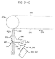
- the paper size indicating means is described below when the electrostatic copying apparatus includes four types of cassettes (A5, B5, A4 and B4 sizes) as described above. Referring to Figures 7-A to 7-D, two indicating positions 266a, 266b are defined at predetermined parts of the front surface of each copying paper cassette 50. In the A5 paper cassette 50 (A5) shown in Figure 7-A, no magnet exists at either of the two indicating positions 266a and 266b.
- the under-surface of the origial-support mechanism 4 has provided thereon a plurality of actuators (first, second, third and fourth actuators 320a, 320b, 320c and 320d in the illustrated embodiment) at predetermined intervals in the moving direction of the original-support mechanism 4.
- a driven member 322 which responds to the actuators 320a, 320b, 320c and 320d.
- the visible paper size displaying means 324 includes an A5-size displayer, a B5-size displayer, an A4-size displayer and a B4-size displayer (not shown) which may be composed of suitable lamps, for example, and an A5-size displayer energizing circuit 326 (A5), a B5-size displayer energizing circuit 326 (B5), an A4-size displayer energizing circuit 326 (A4) and a B4-size displayer energizing circuit 326 (B4) associated respectively with these displayers.
- both of the reed switches 268a and 268b are closed by the mounting of the B-4 size paper cassette 50 (B4) shown in Figure 7-D to the cassette-receiving section 48.
- the B4-size displayer energizing circuit 326 (B4) is actuated whereby the B4-size displayer (not shown) visibly indicates that the B4-size paper cassette 50 (B4) is mounted to the cassette-receiving section 48.
- the read switch 268a is opened and the reed switch 268b is closed to actuate the A4-size displayer energizing circuit 326 (A4) whereby the A4-size displayer (not shown) visibly indicates that the A4-size paper cassette 50 (A4) is mounted to the cassette-receiving section 48.
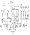
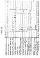
- Figure 12 is a time chart showing the state of operation of various constituent elements of the illustrated electrostatic copying apparatus in conjunction with Figures 2 and 11, controlling of the operations of the original-illuminating lamp 36 of the optical unit 32, the charging corona-discharge device 22 and the transfer corona-discharge device 26, will be described in turn.
- the actuation initiating means comprised of the normally open switch 292 and the timer 328 and capable of starting the actuation of the charging corona-discharge device 22 after the adjustable delay time dt from the closing of the normally open switch 292 can be set or adjusted so that it starts the actuation of the charging corona-discharge device 22 simultaneously with, immediately before, or immediately after, the starting of the scanning movement of the original-support mechanism 4 and therefore the starting of the scanning and exposing of the original document. Conveniently, it is set or adjusted in the following manner with respect to a copying paper transferred from the cassette 50 mounted to the cassette-receiving section 48 through the transfer zone 20.
- the counter 330 When the counter 330 receives the pulse signal with the binary notation being “0”, it produces an output signal. Accordingly, when a signal supplied to the counter 330 from the reed switches 268a and 268b constituting the sensing means of the paper size detecting means is "0" in the binary notation (that is, when the A5-size paper cassette 50 (A5) is mounted to the cassette-receiving section 48), the counter 330 produces an output signal upon receipt of the first pulse signal.
- the time from the stopping of the actuation of the charging corona-discharge device 22 to the stopping of the actuation of the transfer corona discharge device 26, that is the time t 2 defined by the actuation stopping timer 338, can be set at or adjusted to a value substantially equal to, or slightly longer than, the time t 1 defined by the actuation starting timer 334.
- the charging corona-discharge device 22 for charging purposes is actuated only for a period of time which corresponds to the longitudinal size of a copying paper which is contained in the cassette 50 set at the cassette-receiving section 48 and is transferred through the transfer zone 20.
- the longitudinal size (the size in the rotating direction of the rotary drum 12) of a latent electrostatic image formed on the photosensitive member 70 ( Figure 3) on the rotary drum 12 and of a visible image obtained by developing the latent electrostatic image correspond respectively to the longitudinal size of the copying paper transferred through the transfer zone 20.
- a signal is put into a temperature control means 340 which properly controls the state of current supply to the heater of the fixing mechanism 58 according to the temperature of the fixing mechanism 58.
- This input signal causes the temperature control means 340 to interrupt current supply to the heater, and this state in maintained while the input signal exists.
- the temperature control means 340 may interrupt current supply to the heater and be maintained in this state by the input signal, it is also possible, if desired, to cause the temperature control means 340 to continue current supply to the heater (in the alternating-current full-wave state or the alternating-current half-wave state) and be maintained in this state by the input signal.
- the state of the temperature control means 340 at the time of production of the input signal may be maintaned without particlarly changing it.
- the illustrated electrostatic copying apparatus further includes a toner particle dispensing control means shown generally at 342 in Figure 11 which actuates a conventional toner particle dispenser forming part of the developing apparatus 24 only for a time period which corresponds to the longitudinal size of a copying paper transferred through the transfer zone 20 ( Figure 2).
- the toner particle dispensing control means 342 includes a counter 344, a first clock pulse oscillator 346, a second clock pulse oscillator 348 and a circuit 350 for energizing a toner particle dispensing electric motor (not shown).
- the first clock pulse oscillator 346 and the second clock pulse oscillator 348 are connected to the counter 344 through a gate element controlled by a signal from the reed switch 268a.
- the period of the clock pulse generated by the first clock pulse oscillator 346 is set at the time required to dispense an amount of toner particles which corresponds to the amount of toner particles consumed in developing a latent electostatic image according to a standard A5-size original document (that is, the time of rotation required for the paper feed roller 126 to dispense the aforesaid amount of toner particles from the toner particle dispenserto a developer receptacle 94 in the developing device 24).
- the period of the clock pulse generated by the second clock pulse oscillator 348 is set at the time required to dispense an amount of the toner particles which corresponds to the amount of the toner particles consumed in developing a latent electrostatic image according to a standard B5-size original document.
- the reed switch 268b is connected furtherto the counter 344.
- the reed switch 268b is open and therefore the A5-size paper cassette 50 (A5) shown in Figure 7-A or the B5-size paper cassette 50 (B5) is mounted to the cassette-receiving section 48 ( Figure 2), once the counter 344 is actuated as described below, it is maintained in the actuated state only for one period of the clock pulse fed from the first or second dock pulse oscillator 346 or 348.
- the counter 344 is set into operation, it is maintained in the actuated state for one period of the clock pulse generated by the first clock pulse oscillator 346 (therefore, for the time required to dispense an amount of the toner particles which corresponds to the amount of the toner particles consumed in developing a latent electrostatic image according to a standard A5- size original document) when the A5-size paper cassette 50 (A5) is mounted to the cassette-receiving section 48; for one period of the clock pulse generated by the second clock pulse oscillator 348 (therefore, for the time required to dispense an amount of the toner particles which corresponds to the amount of the toner particles consumed in developing a latent electrostatic image according to a standard B5-size original document) when the B5-size paper cassette 50 (B5) is mounted to the cassette-receiving section 48; for 2 periods of the clock pulse generated by the first clock pulse oscillator 346 (therefore, for the time required to dispense an amount
- the counter 344 shown in Figure 11 is started during the rise time of the clock pulse supplied from the first or second clock pulse oscillator 346 or 348 after the lapse of the delay time dt defined by the timer 328 (in the state shown in Figures 11 and 12, during the rise time of the clock pulse fed from the second clock pulse oscillator 348 because the B4-size paper cassette 50 (B4) is mounted) and is maintained in the actuated state for the period of time described hereinabove (for two periods of the clock pulse generated by the second clock pulse oscillator 348 in the state shown in Figures 11 and 12).
- the circuit 350 for energizing the electric motor for toner particle dispensing is maintained in the actuated state, and the electric motor is energized to rotationally drive a feed roller for the period defined by the counter 344 whereby to dispense the toner particles to the developer receptacle.
- an amount of the toner particles which corresponds substantially to the size of a copying paper transferred through the transfer zone 20 ( Figure 2) and therefore the size of a latent electrostatic image formed on the photo-sensitive member 70 ( Figure 3), that is, the amount of the toner particles consumed by the development, is dispensed to the developer receptacle every time the copying process is performed.
Landscapes
- Physics & Mathematics (AREA)
- General Physics & Mathematics (AREA)
- Engineering & Computer Science (AREA)
- Environmental Sciences (AREA)
- Plasma & Fusion (AREA)
- Biodiversity & Conservation Biology (AREA)
- Ecology (AREA)
- Environmental & Geological Engineering (AREA)
- Life Sciences & Earth Sciences (AREA)
- Microelectronics & Electronic Packaging (AREA)
- Atmospheric Sciences (AREA)
- Electrophotography Configuration And Component (AREA)
- Electrostatic Charge, Transfer And Separation In Electrography (AREA)
- Dry Development In Electrophotography (AREA)
- Sheets, Magazines, And Separation Thereof (AREA)
- Control Or Security For Electrophotography (AREA)
- Combination Of More Than One Step In Electrophotography (AREA)
- Paper Feeding For Electrophotography (AREA)
Priority Applications (4)
| Application Number | Priority Date | Filing Date | Title |
|---|---|---|---|
| DE8585103864T DE3176933D1 (en) | 1980-04-15 | 1981-04-15 | Electrostatic copying apparatus |
| DE8585103866T DE3177073D1 (en) | 1980-04-15 | 1981-04-15 | Electrostatic copying apparatus |
| DE8585103868T DE3176839D1 (en) | 1980-04-15 | 1981-04-15 | Electrostatic copying apparatus |
| DE8585103867T DE3177093D1 (en) | 1980-04-15 | 1981-04-15 | Electrostatic copying apparatus |
Applications Claiming Priority (2)
| Application Number | Priority Date | Filing Date | Title |
|---|---|---|---|
| JP4949780A JPS56146155A (en) | 1980-04-15 | 1980-04-15 | Electrostatic copying machine |
| JP49497/80 | 1980-04-15 |
Related Child Applications (4)
| Application Number | Title | Priority Date | Filing Date |
|---|---|---|---|
| EP85103868.7 Division-Into | 1985-03-30 | ||
| EP85103865.3 Division-Into | 1985-03-30 | ||
| EP85103866.1 Division-Into | 1985-03-30 | ||
| EP85103867.9 Division-Into | 1985-03-30 |
Publications (4)
| Publication Number | Publication Date |
|---|---|
| EP0038220A2 EP0038220A2 (en) | 1981-10-21 |
| EP0038220A3 EP0038220A3 (en) | 1983-01-12 |
| EP0038220B1 EP0038220B1 (en) | 1987-03-04 |
| EP0038220B2 true EP0038220B2 (en) | 1991-10-16 |
Family
ID=12832775
Family Applications (6)
| Application Number | Title | Priority Date | Filing Date |
|---|---|---|---|
| EP85103867A Expired EP0167716B1 (en) | 1980-04-15 | 1981-04-15 | Electrostatic copying apparatus |
| EP85103865A Withdrawn EP0166872A1 (en) | 1980-04-15 | 1981-04-15 | Electrostatic copying apparatus |
| EP85103868A Expired EP0166874B1 (en) | 1980-04-15 | 1981-04-15 | Electrostatic copying apparatus |
| EP85103866A Expired EP0166873B1 (en) | 1980-04-15 | 1981-04-15 | Electrostatic copying apparatus |
| EP85103864A Expired EP0166871B1 (en) | 1980-04-15 | 1981-04-15 | Electrostatic copying apparatus |
| EP81301661A Expired - Lifetime EP0038220B2 (en) | 1980-04-15 | 1981-04-15 | Electrostatic copying apparatus |
Family Applications Before (5)
| Application Number | Title | Priority Date | Filing Date |
|---|---|---|---|
| EP85103867A Expired EP0167716B1 (en) | 1980-04-15 | 1981-04-15 | Electrostatic copying apparatus |
| EP85103865A Withdrawn EP0166872A1 (en) | 1980-04-15 | 1981-04-15 | Electrostatic copying apparatus |
| EP85103868A Expired EP0166874B1 (en) | 1980-04-15 | 1981-04-15 | Electrostatic copying apparatus |
| EP85103866A Expired EP0166873B1 (en) | 1980-04-15 | 1981-04-15 | Electrostatic copying apparatus |
| EP85103864A Expired EP0166871B1 (en) | 1980-04-15 | 1981-04-15 | Electrostatic copying apparatus |
Country Status (5)
| Country | Link |
|---|---|
| US (6) | US4382674A (enExample) |
| EP (6) | EP0167716B1 (enExample) |
| JP (1) | JPS56146155A (enExample) |
| CA (1) | CA1174724A (enExample) |
| DE (1) | DE3175958D1 (enExample) |
Families Citing this family (47)
| Publication number | Priority date | Publication date | Assignee | Title |
|---|---|---|---|---|
| US4468113A (en) * | 1981-10-12 | 1984-08-28 | Konishiroku Photo Industry Co., Ltd. | Transfer type electrostatic reproducing apparatus |
| JPS5865674A (ja) * | 1981-10-16 | 1983-04-19 | Ricoh Co Ltd | プリンタ |
| US4613227A (en) * | 1982-02-08 | 1986-09-23 | Canon Kabushiki Kaisha | Image forming apparatus |
| JPS5939629A (ja) * | 1982-08-31 | 1984-03-05 | Konishiroku Photo Ind Co Ltd | 給紙用ユニバ−サルカセツト |
| JPS5986074A (ja) * | 1982-11-09 | 1984-05-18 | Ricoh Co Ltd | 電子写真複写機におけるトナ−補給量の制御方法 |
| JPH0619602B2 (ja) * | 1983-02-28 | 1994-03-16 | 株式会社東芝 | 画像形成装置 |
| JPS59198475A (ja) * | 1983-04-26 | 1984-11-10 | Toshiba Corp | 像形成装置 |
| JPS6078462A (ja) * | 1983-10-06 | 1985-05-04 | Konishiroku Photo Ind Co Ltd | 記録装置 |
| US4639114A (en) * | 1983-10-25 | 1987-01-27 | Kabushiki Kaisha Toshiba | Image-forming apparatus with automatic and manual paper feed modes |
| JPS60182453A (ja) * | 1984-02-29 | 1985-09-18 | Mita Ind Co Ltd | 複写機 |
| USD286542S (en) | 1984-03-07 | 1986-11-04 | Ricoh Company, Ltd. | Developing unit for copying machine |
| JPS60191279A (ja) * | 1984-03-13 | 1985-09-28 | Fuji Xerox Co Ltd | 複写機の制御方法 |
| JPS6132864A (ja) * | 1984-07-26 | 1986-02-15 | Konishiroku Photo Ind Co Ltd | 静電記録装置 |
| JPS6132867A (ja) * | 1984-07-26 | 1986-02-15 | Konishiroku Photo Ind Co Ltd | 静電記録装置 |
| JPS6156370A (ja) * | 1984-08-28 | 1986-03-22 | Ricoh Co Ltd | 画像形成装置 |
| JPS6193463A (ja) * | 1984-10-15 | 1986-05-12 | Fuji Photo Film Co Ltd | 電子写真装置における黒枠除去方法 |
| US4821067A (en) * | 1985-10-31 | 1989-04-11 | Kabushiki Kaisha Toshiba | Microfilm reader-printer having an image fermation device |
| JPH0697365B2 (ja) * | 1985-11-29 | 1994-11-30 | 三田工業株式会社 | 感光体の帯電領域制御装置 |
| JPS62262062A (ja) * | 1986-05-07 | 1987-11-14 | Canon Inc | 画像形成装置 |
| JPS63212624A (ja) * | 1987-02-27 | 1988-09-05 | Canon Inc | シ−ト給送装置 |
| US5008711A (en) * | 1987-04-23 | 1991-04-16 | Ricoh Company, Ltd. | Image forming apparatus |
| JPH01198770A (ja) * | 1987-10-16 | 1989-08-10 | Ricoh Co Ltd | 複写機の制御装置 |
| JP2578841B2 (ja) * | 1987-11-12 | 1997-02-05 | キヤノン株式会社 | 画像形成装置 |
| US5307132A (en) * | 1987-11-12 | 1994-04-26 | Canon Kabushiki Kaisha | Image forming apparatus having a controller for discharging air in response to a heating condition of an image fixing device |
| US4908661A (en) * | 1987-11-27 | 1990-03-13 | Ricoh Company, Ltd. | Holder device for handling an image carrier of an image forming apparatus |
| US4819026A (en) * | 1987-12-21 | 1989-04-04 | Xerox Corporation | Cleaning apparatus for a charge retentive surface |
| US5179636A (en) * | 1988-03-08 | 1993-01-12 | Canon Kabushiki Kaisha | Recording apparatus |
| JP3004990B2 (ja) * | 1988-03-08 | 2000-01-31 | キヤノン株式会社 | プリンタ |
| JP2667440B2 (ja) * | 1988-05-18 | 1997-10-27 | 株式会社東芝 | 画像形成装置 |
| JPH01303252A (ja) * | 1988-05-30 | 1989-12-07 | Fujitsu Ltd | 画像印刷装置 |
| JPH0275653U (enExample) * | 1988-11-29 | 1990-06-11 | ||
| JPH02163764A (ja) * | 1988-12-16 | 1990-06-25 | Minolta Camera Co Ltd | 複写機 |
| US5038170A (en) * | 1989-03-30 | 1991-08-06 | Kabushiki Kaisha Toshiba | Cooling system for an image forming apparatus |
| JP2854611B2 (ja) * | 1989-07-07 | 1999-02-03 | キヤノン株式会社 | 画像形成装置 |
| JPH03147629A (ja) * | 1989-11-01 | 1991-06-24 | Ricoh Co Ltd | 記録紙長検知装置 |
| US5140463A (en) * | 1990-03-08 | 1992-08-18 | Yoo Kwong M | Method and apparatus for improving the signal to noise ratio of an image formed of an object hidden in or behind a semi-opaque random media |
| JPH04151177A (ja) * | 1990-04-10 | 1992-05-25 | Asahi Optical Co Ltd | トナー供給促進機構 |
| US5442421A (en) * | 1990-10-01 | 1995-08-15 | Canon Kabushiki Kaisha | Process cartridge and image forming apparatus using the same |
| JP2577840B2 (ja) * | 1991-10-17 | 1997-02-05 | 三田工業株式会社 | 給紙カセットケース |
| JP2629509B2 (ja) * | 1991-12-17 | 1997-07-09 | 村田機械株式会社 | クリーナレス画像形成装置 |
| JP3131286B2 (ja) * | 1992-05-27 | 2001-01-31 | 沖電気工業株式会社 | 電子写真プリンタ |
| JP3224688B2 (ja) * | 1994-06-07 | 2001-11-05 | キヤノン株式会社 | 画像形成装置 |
| US5477307A (en) * | 1994-09-14 | 1995-12-19 | Xerox Corporation | Apparatus for dispersing and/or transporting particulates |
| US5799228A (en) * | 1995-06-09 | 1998-08-25 | Ricoh Company, Ltd. | Image forming apparatus which prevents adverse affects from heating elements |
| US6510291B2 (en) | 2001-04-19 | 2003-01-21 | Lexmark International, Inc | Toner supply with level sensor and meter and method of using the same |
| JP5393765B2 (ja) * | 2011-12-19 | 2014-01-22 | 京セラドキュメントソリューションズ株式会社 | 現像装置及びそれを備えた画像形成装置 |
| JP6701855B2 (ja) * | 2016-03-22 | 2020-05-27 | コニカミノルタ株式会社 | 画像形成装置 |
Citations (5)
| Publication number | Priority date | Publication date | Assignee | Title |
|---|---|---|---|---|
| US3560087A (en) † | 1967-09-20 | 1971-02-02 | Takaji Washio | Scanning length control for an original supporting slide |
| JPS5273749U (enExample) † | 1975-11-28 | 1977-06-02 | ||
| JPS5474441A (en) † | 1977-11-26 | 1979-06-14 | Canon Inc | Copying machine |
| JPS5543564A (en) † | 1978-09-22 | 1980-03-27 | Ricoh Co Ltd | Electrophotographic copying method |
| US4456366A (en) † | 1977-05-31 | 1984-06-26 | Canon Kabushiki Kaisha | Image forming process control |
Family Cites Families (48)
| Publication number | Priority date | Publication date | Assignee | Title |
|---|---|---|---|---|
| US3114020A (en) * | 1961-05-05 | 1963-12-10 | Beckman Instruments Inc | High resolution digital position transducer including a magnetic switch |
| US3308713A (en) * | 1963-09-30 | 1967-03-14 | Documentation Inc | Portable reader printer |
| US3588472A (en) * | 1966-11-18 | 1971-06-28 | Xerox Corp | Logic control apparatus |
| US3684363A (en) * | 1969-08-30 | 1972-08-15 | Canon Kk | Device for separating recording medium for use in electrophotographic copying machines |
| DE2055321C3 (de) | 1969-11-11 | 1975-11-20 | Katsuragawa Denki K.K., Tokio | Gerät zum Zuführen eines Toners in einer elektrophotographischen Kopiervorrichtung |
| US3647293A (en) * | 1970-12-01 | 1972-03-07 | Ibm | Copying system featuring combined developing-cleaning station alternately activated |
| US3637306A (en) * | 1970-12-02 | 1972-01-25 | Ibm | Copying system featuring alternate developing and cleaning of successive image areas on photoconductor |
| US3692403A (en) * | 1971-12-23 | 1972-09-19 | Xerox Corp | Automatic control of toner concentrations |
| JPS52517Y2 (enExample) * | 1971-12-27 | 1977-01-08 | ||
| JPS48105531U (enExample) * | 1972-03-09 | 1973-12-08 | ||
| NL7305054A (enExample) * | 1972-04-13 | 1973-10-16 | ||
| JPS4912829A (enExample) * | 1972-04-17 | 1974-02-04 | ||
| US3851966A (en) * | 1972-12-11 | 1974-12-03 | Xerox Corp | Reproduction apparatus |
| US3890721A (en) * | 1972-12-26 | 1975-06-24 | Canon Kk | Developing liquid recovery device in a copying machine |
| JPS5422090B2 (enExample) * | 1973-05-08 | 1979-08-04 | ||
| JPS5225152Y2 (enExample) * | 1973-05-18 | 1977-06-08 | ||
| US3936184A (en) * | 1973-05-25 | 1976-02-03 | Canon Kabushiki Kaisha | Electrophotographic copying machine |
| BE821850A (nl) * | 1973-11-12 | 1975-05-05 | Elektrofotografisch kopieerapparaat | |
| JPS5099146A (enExample) * | 1973-12-27 | 1975-08-06 | ||
| AT335195B (de) * | 1974-07-17 | 1977-02-25 | Philips Nv | Aufzeichnungs- und/oder wiedergabegerat und kassette fur ein solches gerat |
| JPS5122206A (en) * | 1974-08-16 | 1976-02-21 | Shimizu Construction Co Ltd | Suraimujokyosochi |
| US3944356A (en) * | 1974-08-29 | 1976-03-16 | Xerox Corporation | Charging apparatus |
| US3950092A (en) | 1974-09-20 | 1976-04-13 | Xerox Corporation | Impeller member for use in transporting particulate material in a reproducing machine |
| US4178092A (en) * | 1974-11-30 | 1979-12-11 | Minolta Camera Kabushiki Kaisha | Electrophotographic copying apparatus with gas evacuating means |
| US4122981A (en) * | 1975-10-18 | 1978-10-31 | Minolta Camera Kabushiki Kaisha | Toner dispensing device having reciprocating dispensing plate and agitator |
| JPS5256939A (en) | 1975-11-06 | 1977-05-10 | Fuji Xerox Co Ltd | Developing apparatus for electronic copying machine |
| DE2618089A1 (de) * | 1976-04-24 | 1977-11-10 | Agfa Gevaert Ag | Vorrichtung zum einfuehren eines einzelnen blattfoermigen kopietraegers in die kopietraegertransportbahn eines kopiergeraetes |
| DE2729591A1 (de) * | 1976-06-30 | 1978-01-12 | Minolta Camera Kk | Elektrophotographisches kopiergeraet |
| JPS5952830B2 (ja) * | 1977-02-01 | 1984-12-21 | キヤノン株式会社 | 画像形成装置の空気流路 |
| GB1597910A (en) * | 1977-05-17 | 1981-09-16 | Ricoh Kk | Sheet feed apparatus |
| DE2729349C3 (de) | 1977-06-29 | 1981-06-25 | Agfa-Gevaert Ag, 5090 Leverkusen | Elektrostatisches Kopiergerät |
| US4270487A (en) * | 1977-10-27 | 1981-06-02 | Hitachi, Ltd. | Developer regulating device in developing apparatus |
| JPS5497041A (en) * | 1978-01-17 | 1979-07-31 | Konishiroku Photo Ind Co Ltd | Zerographic copier |
| JPS5497968A (en) * | 1978-01-19 | 1979-08-02 | Ricoh Co Ltd | Cassette paper feeder |
| JPS5930254B2 (ja) * | 1978-03-09 | 1984-07-26 | ミノルタ株式会社 | 複写領域表示装置 |
| US4259008A (en) * | 1978-04-14 | 1981-03-31 | Mita Industrial Company, Ltd. | Electrostatic copying apparatus |
| JPS54137347A (en) * | 1978-04-18 | 1979-10-25 | Olympus Optical Co Ltd | Zerographic apparatus |
| US4213110A (en) * | 1978-07-20 | 1980-07-15 | Holce Thomas J | Proximity switch having adjustable sensitivity |
| US4347299A (en) | 1978-08-16 | 1982-08-31 | Minolta Camera Kabushiki Kaisha | Method of controlling toner concentration for electrophotographic copying apparatus |
| US4325626A (en) * | 1978-12-13 | 1982-04-20 | Mita Industrial Co., Ltd. | Electrostatic copying apparatus |
| JPS6054660B2 (ja) * | 1979-02-02 | 1985-11-30 | オリンパス光学工業株式会社 | 電子写真装置 |
| DE3009471C2 (de) | 1979-03-15 | 1982-04-29 | Tokyo Shibaura Denki K.K., Kawasaki, Kanagawa | Entwicklertransportvorrichtung für elektrostatische Kopiergeräte |
| US4297029A (en) * | 1979-04-09 | 1981-10-27 | Xerox Corporation | Apparatus and method for diagnostic entry |
| JPS567841A (en) * | 1979-06-25 | 1981-01-27 | Canon Inc | Containing apparatus for copying material |
| US4214696A (en) | 1979-06-27 | 1980-07-29 | Container Corporation Of America | Container with integral partition |
| US4243316A (en) * | 1979-07-25 | 1981-01-06 | Eastman Kodak Company | Registration mechanism |
| JPS6036585B2 (ja) | 1979-11-24 | 1985-08-21 | 株式会社日立製作所 | 現像装置 |
| JPS56137362A (en) * | 1980-03-28 | 1981-10-27 | Minolta Camera Co Ltd | Counter controlling device |
-
1980
- 1980-04-15 JP JP4949780A patent/JPS56146155A/ja active Granted
-
1981
- 1981-04-03 US US06/250,829 patent/US4382674A/en not_active Expired - Lifetime
- 1981-04-06 CA CA000374708A patent/CA1174724A/en not_active Expired
- 1981-04-15 EP EP85103867A patent/EP0167716B1/en not_active Expired
- 1981-04-15 DE DE8181301661T patent/DE3175958D1/de not_active Expired
- 1981-04-15 EP EP85103865A patent/EP0166872A1/en not_active Withdrawn
- 1981-04-15 EP EP85103868A patent/EP0166874B1/en not_active Expired
- 1981-04-15 EP EP85103866A patent/EP0166873B1/en not_active Expired
- 1981-04-15 EP EP85103864A patent/EP0166871B1/en not_active Expired
- 1981-04-15 EP EP81301661A patent/EP0038220B2/en not_active Expired - Lifetime
-
1983
- 1983-02-08 US US06/465,062 patent/US4436411A/en not_active Expired - Lifetime
- 1983-02-08 US US06/465,063 patent/US4478507A/en not_active Expired - Lifetime
- 1983-02-08 US US06/464,833 patent/US4515465A/en not_active Expired - Lifetime
- 1983-02-14 US US06/465,970 patent/US4469431A/en not_active Expired - Lifetime
- 1983-02-14 US US06/465,973 patent/US4469432A/en not_active Expired - Lifetime
Patent Citations (5)
| Publication number | Priority date | Publication date | Assignee | Title |
|---|---|---|---|---|
| US3560087A (en) † | 1967-09-20 | 1971-02-02 | Takaji Washio | Scanning length control for an original supporting slide |
| JPS5273749U (enExample) † | 1975-11-28 | 1977-06-02 | ||
| US4456366A (en) † | 1977-05-31 | 1984-06-26 | Canon Kabushiki Kaisha | Image forming process control |
| JPS5474441A (en) † | 1977-11-26 | 1979-06-14 | Canon Inc | Copying machine |
| JPS5543564A (en) † | 1978-09-22 | 1980-03-27 | Ricoh Co Ltd | Electrophotographic copying method |
Also Published As
| Publication number | Publication date |
|---|---|
| US4469431A (en) | 1984-09-04 |
| EP0166871A1 (en) | 1986-01-08 |
| EP0166873A1 (en) | 1986-01-08 |
| US4469432A (en) | 1984-09-04 |
| EP0038220A2 (en) | 1981-10-21 |
| US4478507A (en) | 1984-10-23 |
| CA1174724A (en) | 1984-09-18 |
| EP0038220A3 (en) | 1983-01-12 |
| EP0167716B1 (en) | 1989-08-30 |
| EP0166873B1 (en) | 1989-06-21 |
| EP0038220B1 (en) | 1987-03-04 |
| US4436411A (en) | 1984-03-13 |
| US4382674A (en) | 1983-05-10 |
| US4515465A (en) | 1985-05-07 |
| EP0167716A1 (en) | 1986-01-15 |
| EP0166871B1 (en) | 1988-11-09 |
| EP0166874A1 (en) | 1986-01-08 |
| JPS56146155A (en) | 1981-11-13 |
| EP0166872A1 (en) | 1986-01-08 |
| JPS646458B2 (enExample) | 1989-02-03 |
| DE3175958D1 (en) | 1987-04-09 |
| EP0166874B1 (en) | 1988-08-10 |
Similar Documents
| Publication | Publication Date | Title |
|---|---|---|
| EP0038220B2 (en) | Electrostatic copying apparatus | |
| EP0082531B1 (en) | Electrostatic copying apparatus | |
| US4307957A (en) | Paper jam detecting device for use in an electrophotographic copying machine | |
| US4522483A (en) | Image forming apparatus | |
| GB2069879A (en) | Developing device for a photocopier | |
| US4763162A (en) | Copy sheet feed controller for an electrostatic copier | |
| US4179112A (en) | Apparatus for conveying sheetlike original material to be copied | |
| EP0001128A1 (en) | Electrophotographic copying machine | |
| US4032225A (en) | Copying machines | |
| EP0103386B1 (en) | Sheet feeder with retractable gate | |
| JPH07215533A (ja) | 画像形成装置およびそのジャム処理制御方法 | |
| JPS62269978A (ja) | 静電複写機のための現像装置 | |
| JPH07215534A (ja) | 画像形成装置およびそのジャム処理制御方法 | |
| JPH0764461A (ja) | 画像形成装置 | |
| KR920007715B1 (ko) | 전자사진 방식을 이용한 기기의 양면 복사 장치 | |
| JPS5820030B2 (ja) | 給紙装置における給紙ロ−ラの制御装置 | |
| JPH0233248Y2 (enExample) | ||
| JPH07239617A (ja) | 画像形成装置 | |
| JP2746437B2 (ja) | キーカウンタ付き電子写真複写機 | |
| JPS6311961A (ja) | 静電複写機 | |
| JPS58176652A (ja) | 複写装置 | |
| JPH09146319A (ja) | 複写機 | |
| JPS6330257B2 (enExample) | ||
| JPH09146318A (ja) | 複写機 | |
| JPS6311664B2 (enExample) |
Legal Events
| Date | Code | Title | Description |
|---|---|---|---|
| PUAI | Public reference made under article 153(3) epc to a published international application that has entered the european phase |
Free format text: ORIGINAL CODE: 0009012 |
|
| AK | Designated contracting states |
Designated state(s): DE FR GB IT NL |
|
| PUAL | Search report despatched |
Free format text: ORIGINAL CODE: 0009013 |
|
| AK | Designated contracting states |
Designated state(s): DE FR GB IT NL |
|
| 17P | Request for examination filed |
Effective date: 19810427 |
|
| GRAA | (expected) grant |
Free format text: ORIGINAL CODE: 0009210 |
|
| AK | Designated contracting states |
Kind code of ref document: B1 Designated state(s): DE FR GB IT NL |
|
| ITF | It: translation for a ep patent filed | ||
| REF | Corresponds to: |
Ref document number: 3175958 Country of ref document: DE Date of ref document: 19870409 |
|
| ET | Fr: translation filed | ||
| PLBI | Opposition filed |
Free format text: ORIGINAL CODE: 0009260 |
|
| 26 | Opposition filed |
Opponent name: CANON INC. Effective date: 19871204 |
|
| NLR1 | Nl: opposition has been filed with the epo |
Opponent name: CANON INC. |
|
| ITTA | It: last paid annual fee | ||
| PUAH | Patent maintained in amended form |
Free format text: ORIGINAL CODE: 0009272 |
|
| STAA | Information on the status of an ep patent application or granted ep patent |
Free format text: STATUS: PATENT MAINTAINED AS AMENDED |
|
| 27A | Patent maintained in amended form |
Effective date: 19911016 |
|
| AK | Designated contracting states |
Kind code of ref document: B2 Designated state(s): DE FR GB IT NL |
|
| ET3 | Fr: translation filed ** decision concerning opposition | ||
| ITF | It: translation for a ep patent filed | ||
| NLR2 | Nl: decision of opposition | ||
| NLR3 | Nl: receipt of modified translations in the netherlands language after an opposition procedure | ||
| PGFP | Annual fee paid to national office [announced via postgrant information from national office to epo] |
Ref country code: GB Payment date: 19970407 Year of fee payment: 17 |
|
| PGFP | Annual fee paid to national office [announced via postgrant information from national office to epo] |
Ref country code: FR Payment date: 19970409 Year of fee payment: 17 |
|
| PGFP | Annual fee paid to national office [announced via postgrant information from national office to epo] |
Ref country code: DE Payment date: 19970418 Year of fee payment: 17 |
|
| PGFP | Annual fee paid to national office [announced via postgrant information from national office to epo] |
Ref country code: NL Payment date: 19970428 Year of fee payment: 17 |
|
| PG25 | Lapsed in a contracting state [announced via postgrant information from national office to epo] |
Ref country code: GB Free format text: LAPSE BECAUSE OF NON-PAYMENT OF DUE FEES Effective date: 19980415 |
|
| PG25 | Lapsed in a contracting state [announced via postgrant information from national office to epo] |
Ref country code: FR Free format text: THE PATENT HAS BEEN ANNULLED BY A DECISION OF A NATIONAL AUTHORITY Effective date: 19980430 |
|
| PG25 | Lapsed in a contracting state [announced via postgrant information from national office to epo] |
Ref country code: NL Free format text: LAPSE BECAUSE OF NON-PAYMENT OF DUE FEES Effective date: 19981101 |
|
| GBPC | Gb: european patent ceased through non-payment of renewal fee |
Effective date: 19980415 |
|
| NLV4 | Nl: lapsed or anulled due to non-payment of the annual fee |
Effective date: 19981101 |
|
| PG25 | Lapsed in a contracting state [announced via postgrant information from national office to epo] |
Ref country code: DE Free format text: LAPSE BECAUSE OF NON-PAYMENT OF DUE FEES Effective date: 19990202 |
|
| REG | Reference to a national code |
Ref country code: FR Ref legal event code: ST |