EP0016352B1 - Einrichtung zur Versorgung von Topfpflanzen - Google Patents
Einrichtung zur Versorgung von Topfpflanzen Download PDFInfo
- Publication number
- EP0016352B1 EP0016352B1 EP80100898A EP80100898A EP0016352B1 EP 0016352 B1 EP0016352 B1 EP 0016352B1 EP 80100898 A EP80100898 A EP 80100898A EP 80100898 A EP80100898 A EP 80100898A EP 0016352 B1 EP0016352 B1 EP 0016352B1
- Authority
- EP
- European Patent Office
- Prior art keywords
- pot
- unit
- tongue
- plant pot
- plant
- Prior art date
- Legal status (The legal status is an assumption and is not a legal conclusion. Google has not performed a legal analysis and makes no representation as to the accuracy of the status listed.)
- Expired
Links
- XLYOFNOQVPJJNP-UHFFFAOYSA-N water Substances O XLYOFNOQVPJJNP-UHFFFAOYSA-N 0.000 claims description 27
- 230000001681 protective effect Effects 0.000 claims description 9
- 235000015097 nutrients Nutrition 0.000 claims description 4
- 238000010521 absorption reaction Methods 0.000 claims description 3
- 238000001704 evaporation Methods 0.000 claims description 3
- 230000008020 evaporation Effects 0.000 claims description 2
- 230000002745 absorbent Effects 0.000 claims 6
- 239000002250 absorbent Substances 0.000 claims 6
- 239000003337 fertilizer Substances 0.000 claims 1
- 230000005923 long-lasting effect Effects 0.000 claims 1
- 230000007935 neutral effect Effects 0.000 claims 1
- 239000003643 water by type Substances 0.000 claims 1
- 238000004382 potting Methods 0.000 abstract description 5
- 230000006978 adaptation Effects 0.000 description 15
- 239000002689 soil Substances 0.000 description 7
- 101100298222 Caenorhabditis elegans pot-1 gene Proteins 0.000 description 6
- 239000000758 substrate Substances 0.000 description 6
- 238000003780 insertion Methods 0.000 description 4
- 230000037431 insertion Effects 0.000 description 4
- 230000002262 irrigation Effects 0.000 description 3
- 238000003973 irrigation Methods 0.000 description 3
- 210000000078 claw Anatomy 0.000 description 2
- 230000008878 coupling Effects 0.000 description 2
- 238000010168 coupling process Methods 0.000 description 2
- 238000005859 coupling reaction Methods 0.000 description 2
- 230000007774 longterm Effects 0.000 description 2
- QVGXLLKOCUKJST-UHFFFAOYSA-N atomic oxygen Chemical compound [O] QVGXLLKOCUKJST-UHFFFAOYSA-N 0.000 description 1
- 239000004927 clay Substances 0.000 description 1
- 239000003501 hydroponics Substances 0.000 description 1
- 238000007654 immersion Methods 0.000 description 1
- 238000004519 manufacturing process Methods 0.000 description 1
- 229910052760 oxygen Inorganic materials 0.000 description 1
- 239000001301 oxygen Substances 0.000 description 1
- 230000002093 peripheral effect Effects 0.000 description 1
- 238000009736 wetting Methods 0.000 description 1
Images




Classifications
-
- A—HUMAN NECESSITIES
- A01—AGRICULTURE; FORESTRY; ANIMAL HUSBANDRY; HUNTING; TRAPPING; FISHING
- A01G—HORTICULTURE; CULTIVATION OF VEGETABLES, FLOWERS, RICE, FRUIT, VINES, HOPS OR SEAWEED; FORESTRY; WATERING
- A01G27/00—Self-acting watering devices, e.g. for flower-pots
- A01G27/04—Self-acting watering devices, e.g. for flower-pots using wicks or the like
Definitions
- the invention relates to a device for supplying potted plants according to the preamble of claim 1.
- Such devices serve to supply the plants with water at least over a longer period of time without watering in the meantime.
- Today one differentiates mainly between two groups.
- One type is commonly known as hydroponic.
- the root system of the plant is fully in the water or a nutrient solution and is only held by a granular, air-permeable substrate.
- the earth is completely removed from the roots of the plants.
- the second, mainly used type is the pure earth culture, combined with a so-called long-term irrigation.
- the plant is pulled into the ground as usual.
- the plant is watered from a water reservoir via a wick arrangement.
- Such an irrigation device for potted plants was known for example from DE-OS 26 10 613.
- the culture pot is placed on a unit with a wick and arranged together with it in a pot that serves as a water reservoir.
- a disadvantage of this arrangement is the direct connection of the suction wick with the potting soil deep into the primary root system. The soil soaks up to absolute saturation, so that the plant is watered over. In connection with the soil, this leads to putrefaction at the root system.
- Another shortcoming can be seen in the fact that, for example, the water supply cannot be increased if you are away on holiday for a longer period.
- FR-PS 1 537 059 is also not applicable to conventional potted plants in connection with simple water-repotting pots. This is a plant trough that holds several plants, in which the water is supplied via suction wicks from cassette-shaped, retractable water containers.
- the object of the invention is to provide a device for the supply of potted plants, which makes it possible to provide different water volumes for holiday supply, can be used in the normal, commercial pots or planters, in which only minor changes to the for the filling with culture pots designed for potting machines is necessary without impairing the use of these machines and which can be easily coupled with such a culture pot.
- the unit with suction wick is coupled to the culture pot via a tongue.
- the tongue which has a large area, carries the suction wick. It is inserted through slot-shaped openings in the culture pot.
- the tongue is connected to a suction mat arranged in the bottom of the culture pot.
- This solution is particularly useful when the plant support consists of an earth core that at least directly surrounds the root core and an air-permeable, capillary substrate surrounding it.
- the adaptation device of the culture pot in the pot which can be realized according to the invention by means of different, constructive solutions, enables a multiplication of the water volume without placing the culture pot in the water bath. Due to the large-area design of the suction wick, reliable humidification of the plant is achieved even at this relatively high suction height. As the level indicator moves along with the unit due to the protective trough, the long-term solution (holiday arrangement) is also fully functional when the culture pot is attached to the unit with regard to overfilling.
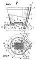
- Fig. 1 shows a device with a unit 2 which is coupled with a culture pot 3 fixed to an assembly.
- the adaptation device 4 and the fill level indicator 5 are attached to the unit 2.
- the level indicator 5, which is molded onto the unit 2 consists essentially of a protective trough 6 with a water inlet opening 7, a guide support 8, a display element 9 and the float 10.
- a guide holder 12 is provided for the display element .
- a tongue 14 is formed from the bottom 13 of the unit 2 and carries the suction wick 15.
- the tongue 14 with suction wick 15 is coupled to the culture pot 3 through a slot-shaped opening 16.
- the possible embodiments of the slot-shaped opening 16 are described in more detail in later examples.
- the suction wick 15 leads into the water reservoir of the pot 1, which is not shown in detail in this example.
- the unit is provided with a raised edge 17 which receives the base 18 of the culture pot 3.
- the opening 16 can be provided as a tear opening.
- the adaptation device 4 is formed by three swivel arms 19 which are fastened to the unit 2 by means of slotted locking pins 20 in holding openings 21.
- the swivel arms 19 are provided with holding claws 22. These holding claws 22 also serve to compensate for the height relative to the protective trough 6 when the assembly is fully inserted into the pot 1.
- the so-called holiday solution with a large water volume is shown in FIGS. 1 and 2.
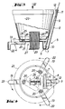
- the exemplary embodiment according to FIGS. 3-6 differs from the device described above in that the coupling of the unit to the culture pot is changed.
- the culture pot 23 is provided on the bottom 24 next to the normal openings 25 with a double T-shaped opening 26. This double-T opening 26 receives the unit 27 via the tongue 28.
- the tongue 28 carries the suction wick 29.
- the level indicator 5 and the adaptation device 4 correspond to the embodiment according to FIGS. 1 and 2.
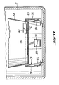
- FIG. 7 to 12 show a further alternative solution of a device.
- the culture pot 30 is coupled to a unit 31 via a tongue 32.
- the tongue 32 carries the suction wick 33.
- the protective trough 35 is molded onto the bottom 34 of the unit 31. This is provided with a lateral opening 36 for inserting the display element 37.
- the display element 37 is angled to accommodate the float 10.
- a holder 40 for the display element 37 of the level indicator is formed at the edge 38 of the unit 31, which engages in a form-fitting manner in the base region 39 of the culture pot 30, a holder 40 for the display element 37 of the level indicator is formed.
- the display element 37 is additionally guided through a groove 41 in the edge area 42 of the culture pot 30.
- sliding arms 43 are provided as an adaptation device. These are guided in a bracket 44 fixed to the floor. Bars 45 provided on the bottom of the pot 1 serve as height compensation for the protective trough 35.
- the culture pot 30 is only indicated by dash-dotted lines
- FIGS. 9 to 12 show two different embodiments of culture pots with a filling funnel. There is no need for any further explanation that these culture pots vary depending on the application and can be adapted to the corresponding facilities.
- the culture pot 46 has a slit-shaped opening 47 with an insertion bevel 48. This opening 47 is formed by a wall cutout 49 above the culture pot base 50, thereby also detecting the wall thickness of the culture pot base.
- the culture pot base is recessed in the area of the insertion slope 48. Furthermore, the normal openings 25 are provided in the culture pot bottom 50.
- the slot-shaped opening 47 is opposite a slot-shaped counter opening 51.
- the culture pot 46 is provided in its upper edge area 52 with a slot 53 for receiving a funnel 54.
- the filling funnel 54 is pushed onto the culture pot wall 56 by means of two holding webs 55.
- the edge area 52 of the culture pot 46 is provided with a groove 57 for guiding a display element, not shown here.
- the culture pot 58 corresponds to the culture pot 46 in the lower area 59.
- the edge area 52 of the culture pot 58 is provided with a slot 60 only on the side of the insertion slope 48.
- the hopper 61 is inserted into this. It is held on the culture pot wall 63 by four fingers 62.
- a guide 64 for the display element, not shown, is formed in the hopper 61.
- FIGS. 13 and 14 show a further alternative solution for a device.
- the pot 65 is provided with webs 66 and 67 arranged at different heights.
- the assembly adapter unit with suction wick and level indicator is designed as a ring 68.
- the adaptation to two different heights, that is to say a normal water reservoir with a larger holiday reservoir, is achieved by turning the assembly bowl 69 ring 68 and placing it on the webs 66 and 67, respectively.
- the ring 68 and the culture pot 69 are connected via the tongue 70, which in turn carries a suction wick 71.
- the ring 68 is provided with a guide cut 72 for guiding the display element 73.
- the filling funnel 61 with guide 64 serves as a second guide for the display element.
- the culture pot is again omitted for better understanding.
- FIG. 1 Another embodiment is shown in Figures 1'5 to 18.
- a tongue 75 and folding arms 76 are formed on the unit 74 via film hinges.
- the tongue 75 has a receiving slot 77 for a suction wick, not shown, a guide notch 78 for the level indicator and locking cams 79.
- the coupling of the unit 74 to a culture pot, e.g. 11, the tongue 75 is inserted into the slot-shaped opening 47 via the insertion slope 48 and pushed out again through the counter opening 51. Then the unit 74 is pivoted in the direction of the arrow 80 and locked by means of the locking cams 79 and the locking receptacles 81.
- the level indicator is arranged according to the exemplary embodiment in FIG. 13. FIG.
- FIG. 17 shows the arrangement of the unit 74 with the culture pot 58 in the pot 1.
- the unit 74 is provided on the peripheral wall 82 with holding openings 83.
- the folding arms 76 are folded into these.
- the folding arms are folded out as shown in FIG. 18 and hung on the edge of the pot 1.
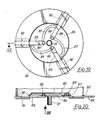
- FIGS. 19 and 20 show a further alternative solution of an adaptation device.
- a control disk 86 with spiral curves 87 is rotatably mounted in a recess 85.
- Control pins 88 of sliding arms 89 engage in the spiral curves 87.
- These sliding arms 89 run in double slots 90 in the bottom 84.
- the sliding arms 89 are adjusted by a rotary knob 91.
- the exemplary embodiments listed are intended to show only a portion of the possible variations according to the invention.
- the examples shown can of course also be varied as desired.
- a further device indicated in FIG. 21 is conceivable, for example, in such a way that the culture pot 58 according to FIG. 11 is only designed with an opening 47 for receiving a suction wick with a tongue.
- the swivel arms 19 are snapped directly into the normal openings 25 of the culture pot 58.
- a display element 73 according to FIG. 13 could be used as a fill level indicator, only an additional guide 99 having to be clipped onto the culture pot 58.
- the suction wick can be covered in a partial area with a protective film 93 to prevent water evaporation.
- the protective film is expediently designed in such a way that only the suction area 94 lying directly in the water and the transfer area 95 remain free in the unit.
Landscapes
- Engineering & Computer Science (AREA)
- Water Supply & Treatment (AREA)
- Life Sciences & Earth Sciences (AREA)
- Environmental Sciences (AREA)
- Cultivation Receptacles Or Flower-Pots, Or Pots For Seedlings (AREA)
Description
- Die Erfindung betrifft eine Einrichtung zur Versorgung von Topfpflanzen gemäss dem Oberbegriff des Anspruches 1.
- Derartige Einrichtungen dienen dazu, die Pflanzen über einen längeren Zeitraum ohne zwischenzeitliches Giessen zumindest mit Wasser zu versorgen. Dabei unterscheidet man heute hauptsächlich unter zwei Gruppen. Die eine Art ist allgemein unter Hydro-Kultur bekannt. Dabei steht das Wurzelwerk der Pflanze voll im Wasser bzw. einer Nährstofflösung und wird lediglich durch ein körniges, luftdurchlässiges Substrat gehalten. Die Erde ist dabei vollkommen von den Wurzeln der Pflanzen entfernt. Die zweite, hauptsächlich angewendete Art ist die reine Erdkultur, verbunden mit einer sogenannten Langzeitbewässerung. Dabei wird die Pflanze wie eh und je rein in Erde gezogen. Die Bewässerung der Pflanze erfolgt dabei aus einem Wasserreservoir über eine Dochtanordnung. Eine derartige Bewässerungsvorrichtung für Topfpflanzen wurde zum Beispiel durch die DE-OS 26 10 613 bekannt. Dabei ist der Kulturtopf auf eine Einheit mit Saugdocht aufgesteckt und zusammen mit dieser in einem Umtopf, der als Wasserreservoir dient, angeordnet. Nachteilig an dieser Ordnung ist die direkte Verbindung des Saugdochtes mit der Blumenerde bis tief in das Primärwurzelwerk. Die Erde saugt sich bis zur absoluten Sättigung voll, so dass die Pflanze überwässert wird. Dies führt in Verbindung mit dem Erdreich zu Fäulniserscheinungen am Wurzelwerk. Ein weiterer Mangel ist darin zu sehen, dass zum Beispiel bei längerer Urlaubsabwesenheit der Wasservorrat nicht erhöht werden kann.
- Durch die französische Patentschrift 1 492 789 Zusatz 95.471 wurde eine Lösung bekannt, bei der es möglich ist, für längere Abwesenheit eine grössere Wassermenge zur Verfügung zu stellen, ohne dass die Pflanze als solche voll im Wasser steht. Dazu dienen auf den Umtopf aufzusetzende Arme, die schwenkbar an einer Schulter des Topfes befestigt sind. Die Schulter nimmt weiter einen Saugdocht auf. Der Kontakt der Blumenerde mit dem Saugdochtende ist bei dieser Ausführung sehr unsicher. Nachteilig kommt noch hinzu, dass sowofil der Kulturtopf als auch der Obertopf speziell aufeinander abgestimmt sein müssen.
- Durch die französische Patentschrift 1 395 154 wurde eine weitere Einrichtung zur Bewässerung von Topfpflanzen bekannt. Diese hat neben den geschilderten Problemen der fehlenden Urlaubslösung den Nachteil, dass das Wasserreservoir und die Einheit mit Saugdocht ganz speziell aufeinander abgestimmt sind. Die Aufnahme in üblichen Umtöpfen bzw. Übertöpfen ist nicht möglich. Dadurch muss der Kulturtopf bereits als Sichttopf ausgebildet werden. Zudem kommt eine spezielle, recht aufwendige Adaptionseinrichtung mit der Einheit mit Saugdocht hinzu. Dadurch wird die Baugruppe recht teuer, so dass sie nur schwer einem breiten Anwendungsbereich zugänglich ist.
- Auch die Ausführung nach der FR-PS 1 537 059 ist auf übliche Topfpflanzen in Verbindung mit einfachen, das Wasser aufnehmenden Um- bzw. Übertöpfen nicht anwendbar. Es handelt sich hier um einen mehrere Pflanzen aufnehmenden Pflanzentrog, bei dem die Wasserversorgung über Saugdochte aus kassettenförmig einschiebbaren Wasserbehältern erfolgt.
- Aufgabe der Erfindung ist es, eine Einrichtung zur Versorgung von Topfpflanzen zu schaffen, die es ermöglicht, unterschiedliche Wasservolumina zur Urlaubsversorgung zur Verfügung zu stellen, bei der normale, handelsübliche Um- bzw. Übertöpfe verwendet werden können, bei der nur geringfügige Änderungen an den für die Befüllung mit Topfmaschinen ausgelegten Kulturtöpfen ohne Beeinträchtigung des Einsatzes dieser Maschinen notwendig sind und die einfach mit einem derartigen Kulturtopf zu koppeln ist..
- Diese Aufgabe wird durch die kennzeichnenden Merkmale des Anspruches 1 gelöst. Durch die flächige Ausbildung des Saugdochtes wird, verbunden mit einer hervorragenden Sauerstoffaufnahme, eine gleichmässige, breitflächige Benässung des Pflanzenträgers erreicht.
- Eine punktuale, dem Wurzelwerk schädliche Ubernässung, wie sie durch zylindrische Dochtsysteme nicht zu verhindern ist, wird gänzlich ausgeschlossen. Durch die integrierte Adaptionsvorrichtung können, zum Beispiel bei längerer Urlaubsabwesenheit, auch grössere Wasservolumina vorgesehen werden, ohne dass irgendwelche Nachteile für die Pflanze auftreten. Ein weiterer Vorteil ist darin zu sehen, dass alle Bauteile miteinander gekoppelt sind, so dass eine einfache, störungsfreie Handhabung gewährleistet ist. Fehlerquellen sind weitgehend ausgeschlossen. Umständliche Montagearbeiten müssen nicht durchgeführt werden. So erfolgt die Kopplung der Einheit mit Saugdocht mit dem Kulturtopf über eine Zunge. Die Zunge, grossflächig ausgebildet, trägt den Saugdocht. Sie wird über schlitzförmige Öffnungen im Kulturtopf eingeführt. Das hat den Vorteil, dass am Kulturtopf selbst gegenüber den heute allgemein gebräuchlichen Kulturtöpfen nur ganz geringfügige Änderungen durchgeführt werden müssen. Im einfachsten Fall ist eben nur die eine, schlitzförmige Öffnung erforderlich. Dadurch kann der Kulturtopf nach wie vor über automatische Topfmaschinen gefüllt werden.
- Um eine noch grossflächigere Befeuchtung des Pflanzenträgers zu erreichen, ist die Zunge an eine im Boden des Kulturtopfes angeordnete Saugmatte angeschlossen. Diese Lösung bietet sich besonders dann an, wenn der Pflanzenträger aus einem zumindest den Wurzelkern unmittelbar einschliessenden Erdkern und einem diesen umgebenden luftdurchlässigen, kapillaren Substrat besteht.
- Diese Anordnung ermöglicht eine einfache Realisierung der Hydro-Kultur ohne die bislang allgemein bekannten Schwierigkeiten. Bei der Hydro-Kultur, wie sie derzeit praktiziert wird, ist es erforderlich, spezielle Pflanzen zu züchten. Diese Pflanzen bzw. deren Wurzeln müssen vollkommen vom Erdreich gesäubert werden, bevor sie in das Substrat, in aller Regel Blähton, eingesetzt werden. Dagegen ist es bei der erfindungsgemässen Einrichtung nicht erforderlich, dass die Wurzeln der Pflanzen vom Erdreich gereinigt werden. Die Pflanzen werden dabei mit dem sogenannten Wurzelballen in den Kulturtopf eingesetzt und von einem luftdurchlässigen, kapillaren Substrat umgeben. Dabei spielt es keine Rolle, wieviel Erde noch am Wurzelwerk der Pflanze haften bleibt. Die Pflanze wird ohnehin nach einiger Zeit den Erdballen mit den Wurzeln durchdringen und sich im Substrat verankern. Die Bewässerung und gegebenenfalls die Nährstoffzufuhr erfolgt dann über den flächigen Docht, gegebenenfalls die Saugmatte, die aber nicht zwingend erforderlich ist, über das Substrat in den Wurzelkern.
- Die Adaptionsvorrichtung des Kulturtopfes im Umtopf, die erfindungsgemäss durch unterschiedliche, konstruktive Lösungen verwirklicht werden kann, ermöglicht eine Vervielfachung des Wasservolumens ohne den Kulturtopf ins Wasserbad zu stellen. Durch die grossflächige Ausbildung des Saugdochtes wird auch bei dieser relativ grossen Saughöhe eine zuverlässige Befeuchtung der Pflanze erreicht. Da der Füllstandsanzeiger, bedingt durch die Schutzwanne an der Einheit mitwandert, ist auch bei der Einhängung des Kulturtopfes in der Langzeitlösung (Urlaubsanordnung) diese bezüglich einer Überfüllung voll funktionsfähig.
- Einige Ausführungsbeispiele der Erfindung werden im folgenden anhand der Zeichnungen näher erläutert.
- Es zeigen:
-
- Fig. 1 einen Kulturtopf mit festgekoppelter Einheit sowie Adaptionsvorrichtung und Füllstandsanzeige aufgesetzt auf einen schematisch angedeuteten Umtopf,
- Fig. 2 eine Ansicht gemäss Richtung II nach Fig. 1 ohne Umtopf mit schematisch angedeutetem Kulturtopf,
- Fig. 3 eine Alternativlösung gemäss Fig. 1,
- Fig. 4 eine Ansicht in Richtung IV nach Fig. 3,
- Fig. 5 den Kulturtopf nach Fig. 11,1 teilweise geschnitten,
- Fig. 6 eine Ansicht gemäss Richtung VI in Fig. 5,
- Fig. 7 eine weitere Alternativlösung gemäss Fig. 1 mit schematisch angedeutetem Kulturtopf, der damit gekoppelten Einheit, Füllstandsanzeiger und Adaptionsvorrichtung eingesetzt in einen Umtopf,
- Fig. 8 eine Ansicht gemäss Richtung VIII in Fig. 7,
- Fig. 9 einen Kulturtopf mit schlitzförmiger Öffnung mit Einführschräge, mit Gegenöffnung, mit Einfülltrichter und Einnutung zur Führung eines Anzeigeelementes,
- Fig. 10 eine Ansicht in Richtung X nach Fig. 9,
- Fig. 11 eine Alternativlösung eines Kulturtopfes nach Fig. 9,
- Fig. 12 eine Ansicht in Richtung XII nach Fig. 11,
- Fig. 13 eine weitere Alternativlösung einer Einrichtung mit einer in Form eines Ringes ausgeführten Adaptionsvorrichtung,
- Fig. 14 eine Ansicht gemäss Richtung XIV nach Fig. 13,
- Fig. 15 eine weitere Alternativlösung einer Einheit mit Adaptionsvorrichtung im Fertigungszustand,
- Fig. 16 die Einheit gemäss Fig. 15 eingeführt in einen Kulturtopf,
- Fig. 17 die Einheit im Kulturtopf verriegelt und in einen Umtopf eingesetzt,
- Fig. 18 die Adaptionsvorrichtung ausgefahren und auf einen Umtopf aufgesetzt,
- Fig. 19 eine Alternativlösung einer Adaptionsvorrichtung,
- Fig. 20 einen Schnitt gemäss der Linie XX nach
- Fig. 19, wobei auf der linken Bildhälfte der Schiebearm eingefahren und auf der rechten Bildhälfte der Schiebearm ausgefahren ist und
- Fig. 21 eine Einrichtung komplett mit Pflanze.
- Nur für absolut identische Teile werden im folgenden die gleichen Bezugszeichen gewählt. Weicht ein Teil in seiner konstruktiven Ausbildung, auch wenn es die identische Funktion erfüllt, etwas vom vorhergehenden ab, wird ein neues Bezugszeichen verwendet.
- Fig. 1 zeigt eine Einrichtung mit einer Einheit 2 die mit einem Kulturtopf 3 fest zu einer Baugruppe gekoppelt ist. An der Einheit 2 sind die Adaptionsvorrichtung 4 und die Füllstandsanzeige 5 angebracht. Die Füllstandsanzeige 5, die an die Einheit 2 angeformt ist, besteht im wesentlichen aus einer Schutzwanne 6 mit einer Wassereinlauföffnung 7, einem Führungsträger 8, einem Anzeigeelement 9 und dem Schwimmer 10. Am Ende 11 des Führungsträgers 8 ist eine Führungshalterung 12 für das Anzeigeelement vorgesehen.
- Aus dem Boden 13 der Einheit 2 ist eine Zunge 14 ausgeformt, die den Saugdocht 15 trägt. Die Zunge 14 mit Saugdocht 15 ist durch eine schlitzförmige Öffnung 16 im Kulturtopf 3 mit diesem gekoppelt. Die möglichen Ausführungsformen der schlitzförmigen Öffnung 16 werden in späteren Beispielen noch näher beschrieben. Der Saugdocht 15 führt in das bei diesem Beispiel nicht näher dargestellte Wasserreservoir des Umtopfes 1. Zur formschlüssigen Verbindung der Einheit 2 mit dem Kulturtopf 3 ist die Einheit mit einem hochgezogenen Rand 17 versehen, der den Sokkel 18 des Kulturtopfes 3 aufnimmt. Die Öffnung 16 kann als Aufreissöffnung vorgesehen sein.
- Die Adaptionsvorrichtung 4 wird bei diesem Ausführungsbeispiel durch drei Schwenkarme 19, die über geschlitzte Rastzapfen 20 in Halteöffnungen 21 an der Einheit 2 befestigt sind, gebildet.
- Zum sicheren Halt am Umtopf 1 sind die Schwenkarme 19 mit Haltekrallen 22 versehen. Diese Haltekrallen 22 dienen gleichzeitig zum Höhenausgleich gegenüber der Schutzwanne 6 beim vollen Einsetzen der Baugruppe in den Umtopf 1. Dargestellt ist in den Figuren 1 und 2 die sogenannte Urlaubslösung mit grossem Wasservolumen.
- Das Ausführungsbeispiel gemäss den Figuren 3 - 6 unterscheidet sich von der vorab geschilderten Einrichtung durch eine geänderte Kopplung der Einheit an den Kulturtopf. Der Kulturtopf 23 ist am Boden 24 neben den Normalöffnungen 25 mit einer doppel-T-förmigen Öffnung 26 versehen. Diese Doppel-T-Öffnung 26 nimmt die Einheit 27 über die Zunge 28 auf. Die Zunge 28 trägt den Saugdocht 29. Die Füllstandsanzeige 5 und die Adaptionsvorrichtung 4 entsprechen der Ausführung gemäss den Figuren 1 und 2.
- Die Figuren 7 bis 12 zeigen eine weitere Alternativlösung einer Einrichtung. Der Kulturtopf 30 ist mit einer Einheit 31 über eine Zunge 32 gekoppelt. Die Zunge 32 trägt den Saugdocht 33. An den Boden 34 der Einheit 31 ist die Schutzwanne 35 angeformt. Diese ist mit einer seitlichen Öffnung 36 zum Einführen des Anzeigeelementes 37 versehen. Das Anzeigeelement 37 ist zur Aufnahme des Schwimmers 10 abgewinkelt. Am Rand 38 der Einheit 31, er greift formschlüssig in den Sockelbereich 39 des Kulturtopfes 30 ein, ist eine Halterung 40 für das Anzeigeelement 37 der Füllstandsanzeige angeformt. Das Anzeigeelement 37 wird zusätzlich durch eine Einnutung 41 im Randbereich 42 des Kulturtopfes 30 geführt. Am Boden 34 der Einheit 31 sind als Adaptionsvorrichtung Schiebearme 43 vorgesehen. Diese sind in einer bodenfesten Halterung 44 geführt. Als Höhenausgleich für die Schutzwanne 35 dienen am Boden des Umtopfes 1 vorgesehene Stege 45. Der Kulturtopf 30 ist in Fig. 8 nur strichpunktiert angedeutet.
- Die Figuren 9 bis 12 zeigen zwei verschiedene Ausführungsformen von Kulturtöpfen mit Einfülltrichter. Es bedarf dabei keiner näheren Erläuterung, dass diese Kulturtöpfe je nach Anwendung variiert und den entsprechenden Einrichtungen angepasst werden können.
- Der Kulturtopf 46 hat eine schlitzförmige Öffnung 47 mit Einführschräge 48. Diese Öffnung 47 wird durch einen Wandausschnitt 49 über dem Kulturtopfboden 50, dabei den Kulturtopfboden in Wandstärke miterfassend, gebildet. Der Kulturtopfboden ist im Bereich der Einführschräge 48 ausgespart. Weiter sind im Kulturtopfboden 50 die Normalöffnungen 25 vorgesehen. Der schlitzförmigen Öffnung 47 liegt eine schlitzförmige Gegenöffnung 51 gegenüber. Der Kulturtopf 46 Ist in seinem oberen Randbereich 52 mit einem Schlitz 53 zur Aufnahme eines Einfülltrichters 54 versehen. Der Einfülltrichter 54 ist mittels zwei Haltestege 55 auf die Kulturtopfwand 56 aufgeschoben. Auf der dem Einfülltrichter gegenüberliegenden Seite ist der Randbereich 52 des Kulturtopfes 46 mit einer Einnutung 57 zur Führung eines hier nicht dargestellten Anzeigeelementes versehen. Der Kulturtopf 58 gemäss den Figuren 11 und 12 entspricht im unteren Bereich 59 dem Kulturtopf 46. Der Randbereich 52 des Kulturtopfes 58 ist dabei nur auf der Seite der Einführschräge 48 mit einem Schlitz 60 versehen. In diesem ist der Einfülltrichter 61 eingeschoben. Er wird dabei über vier Finger 62 auf der Kulturtopfwand 63 gehalten. Zusätzlich ist im Einfülltrichter 61 eine Führung 64 für das nicht dargestellte Anzeigeelement angeformt.
- Die Figuren 13 und 14 zeigen eine weitere Alternativlösung einer Einrichtung. Der Umtopf 65 ist dabei mit in unterschiedlichen Höhen angeordneten Stegen 66 und 67 versehen. Die Baugruppe Adaptionsvorrichtung-Einheit mit Saugdocht und Füllstandsanzeige ist dabei als Ring 68 ausgebildet. Die Adaption in zwei verschiedene Höhen, also normal Wasserreservoir vergrössertes Urlaubsreservoir, wird durch Drehen der Baugruppe Kulturtopf 69-Ring 68 und Auflage auf den Stegen 66 bzw. 67 erreicht.
- Die Verbindung Ring 68 und Kulturtopf 69 erfolgt über die Zunge 70, die wiederum einen Saugdocht 71 trägt. Der Ring 68 ist mit einem Führungseinschnitt 72 zur Führung des Anzeigeelementes 73 versehen. Als zweite Führung für das Anzeigeelement dient der Einfülltrichter 61 mit Führung 64. In Fig. 14 ist wiederum der Kulturtopf zum besseren Verständnis weggelassen.
- Ein weiteres Ausführungsbeispiel ist in den Figuren 1'5 bis 18 dargestellt. An die Einheit 74 sind über 'Filmscharniere eine Zunge 75 und Klapparme 76 angeformt. Die Zunge 75 hat einen Aufnahmeschlitz 77 für einen nicht dargestellten Saugdocht, einen Führungseinschnitt 78 für die Füllstandsanzeige und Rastnocken 79. Die Kopplung der Einheit 74 an einen Kulturtopf, z.B. dem Kulturtopf 58 gemäss Fig. 11, erfolgt dadurch, dass die Zunge 75 über die Einführschräge 48 in die schlitzförmige Öffnung 47 eingeschoben und durch die Gegenöffnung 51 wieder herausgeschoben wird. Danach wird die Einheit 74 in Pfeilrichtung 80 herumgeschwenkt und mittels der Rastnocken 79 und der Rastaufnahmen 81 verrastet. Die Anordnung der Füllstandsanzeige erfolgt gemäss dem Ausführungsbeispiel Fig. 13. Fig. 17 zeigt die Anordnung der Einheit 74 mit Kulturtopf 58 im Umtopf 1. Die Einheit 74 ist an der Umfangswand 82 mit Halteöffnungen 83 versehen. In diese sind bei Niedrigniveau des Wassers die Klapparme 76 eingeklappt. Bei der sogenannten Urlaubslösung werden gemäss Fig. 18 die Klapparme ausgeklappt und am Rand des Umtopfes 1 eingehängt.
- Die Figuren 19 und 20 zeigen eine weitere Alternativlösung einer Adaptionsvorrichtung.
- Auf dem Boden 84 eines Kulturtopfes oder einer Einheit ist in einer Vertiefung 85 eine Steuerscheibe 86 mit Spiralkurven 87 drehbar gelagert. In die Spiralkurven 87 greifen Steuerstifte 88 von Schiebearmen 89 ein. Diese Schiebearme 89 laufen in Doppelschlitze 90 des Bodens 84. Verstellt werden die Schiebearme 89 durch einen Drehknopf 91.
- Die aufgeführten Ausführungsbeispiele sollen nur einen Ausschnitt der erfindungsgemässen Variationsmöglichkeiten zeigen. So sind diese dargestellten Beispiele natürlich auch beliebig untereinander variierbar. Eine weitere, in Fig. 21 angedeutete Einrichtung ist zum Beispiel derart denkbar, dass der Kulturtopf 58 gemäss Fig. 11 nur mit einer Öffnung 47 zur Aufnahme eines Saugdochtes mit Zunge ausgeführt wird. Als Adaptionsvorrichtung werden die Schwenkarme 19 unmittelbar in die Normalöffnungen 25 des Kulturtopfes 58 eingerastet. Als Füllstandsanzeige könnte ein Anzeigeelement 73 gemäss Fig. 13 zur Anwendung kommen, wobei am Kulturtopf 58 lediglich eine zusätzliche Führung 99 einzuklipsen wäre.
- Des weiteren kann der Saugdocht, wie in Fig: 21 dargestellt, in einem Teilbereich mit einer Schutzfolie 93 zur Verhinderung der Wasserverdunstung überzogen werden. Dadurch wird verhindert, dass bei starkerSonneneinstrahlung und der Urlaubslösung zuviel Wasser auf dem Saugweg verdunstet. Die Schutzfolie wird dabei zweckmässigerweise so ausgeführt, dass nur der unmittelbar im Wasser liegende Saugbereich 94 und der Übergabebereich 95 in der Einheit freibleibt. Um ein sicheres Eintauchen in das Wasser zu gewährleisten, ist es bei dieser Ausführungsform zweckmässig, das Dochtende mit einem Ballastgewicht 96 zu versehen.


Claims (23)
Priority Applications (1)
| Application Number | Priority Date | Filing Date | Title |
|---|---|---|---|
| AT80100898T ATE2181T1 (de) | 1979-03-15 | 1980-02-25 | Einrichtung zur versorgung von topfpflanzen. |
Applications Claiming Priority (2)
| Application Number | Priority Date | Filing Date | Title |
|---|---|---|---|
| DE2910217A DE2910217C2 (de) | 1979-03-15 | 1979-03-15 | Einrichtung zur Versorgung von Topfpflanzen |
| DE2910217 | 1979-03-15 |
Publications (2)
| Publication Number | Publication Date |
|---|---|
| EP0016352A1 EP0016352A1 (de) | 1980-10-01 |
| EP0016352B1 true EP0016352B1 (de) | 1983-01-12 |
Family
ID=6065501
Family Applications (1)
| Application Number | Title | Priority Date | Filing Date |
|---|---|---|---|
| EP80100898A Expired EP0016352B1 (de) | 1979-03-15 | 1980-02-25 | Einrichtung zur Versorgung von Topfpflanzen |
Country Status (6)
| Country | Link |
|---|---|
| US (1) | US4420904A (de) |
| EP (1) | EP0016352B1 (de) |
| AT (1) | ATE2181T1 (de) |
| DE (1) | DE2910217C2 (de) |
| ES (1) | ES489568A1 (de) |
| NL (1) | NL7906171A (de) |
Families Citing this family (14)
| Publication number | Priority date | Publication date | Assignee | Title |
|---|---|---|---|---|
| DE2951628C2 (de) * | 1979-12-21 | 1985-06-27 | Leifheit AG, 5408 Nassau | Einrichtung zur Versorgung von Topfpflanzen mit Wasser, Luft und gegebenenfalls Nährstoffen |
| FR2588443B1 (fr) * | 1985-10-15 | 1987-12-31 | Barns | Grille pour bac a plantes a reserve d'eau et bac a plantes comportant une telle grille |
| US4916858A (en) * | 1987-08-03 | 1990-04-17 | Rubbermaid Incorporated | Self-watering planter |
| USD331549S (en) | 1991-04-01 | 1992-12-08 | Rubbermaid Incorporated | Planter |
| ES2048115B1 (es) * | 1992-09-01 | 1994-11-16 | Plastic Omnium Cie | Jardinera modular. |
| ES2080695B1 (es) * | 1994-07-13 | 1996-09-16 | Gumbau Agusti Ortuno | Jardinera con riego alternativo doble. |
| US5937574A (en) * | 1997-05-16 | 1999-08-17 | Jacques; David R. | Apparatus and method for supplying liquid to a tree stand |
| US6226921B1 (en) * | 1999-02-22 | 2001-05-08 | Gaasbeck U.S.A., Inc. | Self-watering planter |
| EP1232685A3 (de) * | 2001-02-16 | 2004-01-07 | Lutz Bengsch | Vorrichtung zum Bewässern eines Blumentopfes |
| US20080313960A1 (en) * | 2007-06-19 | 2008-12-25 | Norvitch Daniel A | Mobile planter |
| US20090064576A1 (en) * | 2007-09-10 | 2009-03-12 | Steven Lee Sugarek Sugarek | Potted plant watering system |
| US8528252B2 (en) * | 2009-08-13 | 2013-09-10 | Arthur Francis Griebel | Self watering plant system |
| US20130333780A1 (en) * | 2012-06-19 | 2013-12-19 | Tien-Yin Chan | Water supply base of a plant pot |
| US20260107888A1 (en) * | 2024-10-21 | 2026-04-23 | Raj Kagathi | Potted plant watering assembly |
Family Cites Families (21)
| Publication number | Priority date | Publication date | Assignee | Title |
|---|---|---|---|---|
| DE7145371U (de) * | 1972-03-09 | Akzo Gmbh | Pflanzengrund | |
| US2072172A (en) * | 1935-12-16 | 1937-03-02 | Robert H Lockyer | Combination flowerpot |
| DE706853C (de) * | 1936-06-08 | 1941-06-06 | Martin Luechinger Dr | Pflanzenbehaelter |
| CH312692A (de) * | 1953-07-22 | 1956-02-29 | Francois Wyss Soehne Ag | Bewässerungseinrichtung für Topfpflanzen |
| DE1704327U (de) * | 1954-12-17 | 1955-08-11 | Otto Goebel | Verstellbare vorrichtung zur selbsttaetigen regulierbaren bewaesserung von topfpflanzen od. dgl. |
| FR1152961A (fr) * | 1956-06-05 | 1958-02-27 | Grille-support pour l'arrosage par capillarité des plantes en pot | |
| DE1030096B (de) * | 1957-02-26 | 1958-05-14 | Georg Katz | Bewaesserungsvorrichtung fuer Topfpflanzen |
| FR1395186A (fr) * | 1963-07-15 | 1965-04-09 | Récipients décoratifs pour plantes en culture | |
| NL6404038A (de) * | 1964-04-14 | 1965-10-15 | ||
| FR1492789A (fr) * | 1965-07-23 | 1967-08-25 | Perfectionnements apportés aux récipients permettant la culture des plantes en milieu non adapté | |
| NL6711673A (de) * | 1966-08-27 | 1968-02-28 | ||
| FR1537059A (fr) * | 1967-07-04 | 1968-08-23 | Georges Et Paul Guilbert Soc | Bac-jardinière pour la culture de plantes diverses, muni d'un dispositif humectant le milieu de culture |
| US3739524A (en) * | 1971-06-23 | 1973-06-19 | H Rose | Plant-holding receptacles |
| CH572301A5 (en) * | 1973-12-17 | 1976-02-13 | Hortechnica Ag | Plastic plant container watering saucer - has parts joined by centering pins fitting in indentations in base |
| FR2255843A1 (en) * | 1973-12-26 | 1975-07-25 | Chatenoud Gilles | Device for watering plants in window boxeseetc - has water container, wick, distributor and filler pipe |
| DE2419703A1 (de) * | 1974-04-24 | 1975-11-06 | Schulz Hans Joachim | Vorrichtung zur dauerbefeuchtung von pflanzen in beliebigen behaeltern |
| DE2437141A1 (de) * | 1974-08-01 | 1976-02-19 | Hans Ekkehard Lommerzheim | Docht |
| DE2610613A1 (de) * | 1976-03-13 | 1977-09-15 | Kunststoffabrik Erich Dittrich | Bewaesserungs-vorrichtung fuer topfpflanzen |
| DE2631116A1 (de) * | 1976-07-10 | 1978-01-19 | Schock & Co Gmbh | Pflanzenbehaelter |
| DE2725332A1 (de) * | 1977-06-04 | 1978-12-07 | Wolfgang Pfannebecker | Automatische wasserzuteilungsvorrichtung fuer blumentoepfe und blumenkaesten |
| DE7734432U1 (de) * | 1977-11-10 | 1978-04-20 | Helfert, Hermann, 6200 Wiesbaden | Bewaesserungsvorrichtung fuer pflanzentoepfe, pflanzenschalen und pflanzenkaesten |
-
1979
- 1979-03-15 DE DE2910217A patent/DE2910217C2/de not_active Expired
- 1979-08-13 NL NL7906171A patent/NL7906171A/nl not_active Application Discontinuation
-
1980
- 1980-02-25 AT AT80100898T patent/ATE2181T1/de not_active IP Right Cessation
- 1980-02-25 EP EP80100898A patent/EP0016352B1/de not_active Expired
- 1980-03-14 ES ES489568A patent/ES489568A1/es not_active Expired
-
1983
- 1983-03-30 US US06/480,511 patent/US4420904A/en not_active Expired - Fee Related
Also Published As
| Publication number | Publication date |
|---|---|
| ES489568A1 (es) | 1980-09-16 |
| NL7906171A (nl) | 1980-09-17 |
| DE2910217A1 (de) | 1980-09-18 |
| US4420904A (en) | 1983-12-20 |
| DE2910217C2 (de) | 1984-05-10 |
| EP0016352A1 (de) | 1980-10-01 |
| ATE2181T1 (de) | 1983-01-15 |
Similar Documents
| Publication | Publication Date | Title |
|---|---|---|
| DE3240269C1 (de) | Pflanzengefaess,insbesondere fuer Hydrokultur | |
| DE819017C (de) | Bewaesserungsvorrichtung, insbesondere fuer Topfpflanzen | |
| DE3225263C2 (de) | Einrichtung zur Haltung von Pflanzen mit einer ein geschlossenes System bildenden Pflanzsäule | |
| EP0016352A1 (de) | Einrichtung zur Versorgung von Topfpflanzen | |
| AT520103B1 (de) | Blumentopf | |
| DE837332C (de) | Vorrichtung zur selbsttqaetigen Bewaesserung von in Toepfen, Kaesten oder Schalen eingesetzten Pflanzen | |
| DE2509724C2 (de) | Übertopf zum Bewässern von Topfpflanzen | |
| DE2447230A1 (de) | Bewaesserungssonde fuer pflanzgefaesse, insbesondere blumentoepfe und damit ausgeruesteter bewaesserungsbehaelter | |
| DE2645994C2 (de) | Bepflanzgefäß | |
| DE2539552A1 (de) | Hydro-pflanzgefaess | |
| EP0230463A1 (de) | Pflanzentopf für pflanzen mit einem verringerten wurzelvolumen | |
| DE2918332A1 (de) | Vorrichtung zur pflanzenbewaesserung | |
| DE3440616A1 (de) | Pflanzgefaess, wie blumentopf oder -schale, fuer selbstbewaesserung | |
| DE3211985A1 (de) | Pflanzenbehaelter oder -topf | |
| DE19610241C2 (de) | Vorrichtung zur Langzeitbefeuchtung des Wurzelballens von Topfpflanzen | |
| DE3304800C2 (de) | Hohlspieß für eine Anordnung zum Gießen von Kulturen in Gartenbaubetrieben, Gewächshäusern oder dgl. | |
| DE2628392A1 (de) | Bewaesserungsvorrichtung fuer topfpflanzen | |
| DE2820540C2 (de) | Hydrokulturanlage | |
| DE102022123425B3 (de) | Haltevorrichtung für mindestens ein Saatkorn und eine daraus wachsende Pflanze | |
| DE29916725U1 (de) | Blumen- und Pflanzgefäß | |
| DE1611810B2 (de) | Staender zum bereithalten von tuschefuellern | |
| EP1232685A2 (de) | Vorrichtung zum Bewässern eines Blumentopfes | |
| DE2364868C3 (de) | Pflanzentopf bzw. -gefäß mit Eigenbewässerung | |
| DE19617031C1 (de) | Wasserstandsanzeiger für Pflanzsubstrat | |
| DE8203635U1 (de) | Bewässerungsvorrichtung für Topfpflanzen |
Legal Events
| Date | Code | Title | Description |
|---|---|---|---|
| PUAI | Public reference made under article 153(3) epc to a published international application that has entered the european phase |
Free format text: ORIGINAL CODE: 0009012 |
|
| AK | Designated contracting states |
Designated state(s): AT BE CH FR GB IT NL |
|
| 17P | Request for examination filed |
Effective date: 19810128 |
|
| ITF | It: translation for a ep patent filed | ||
| GRAA | (expected) grant |
Free format text: ORIGINAL CODE: 0009210 |
|
| AK | Designated contracting states |
Designated state(s): AT BE CH FR GB IT NL |
|
| REF | Corresponds to: |
Ref document number: 2181 Country of ref document: AT Date of ref document: 19830115 Kind code of ref document: T |
|
| ET | Fr: translation filed | ||
| PGFP | Annual fee paid to national office [announced via postgrant information from national office to epo] |
Ref country code: FR Payment date: 19840229 Year of fee payment: 5 |
|
| PGFP | Annual fee paid to national office [announced via postgrant information from national office to epo] |
Ref country code: BE Payment date: 19840331 Year of fee payment: 5 |
|
| PGFP | Annual fee paid to national office [announced via postgrant information from national office to epo] |
Ref country code: CH Payment date: 19840516 Year of fee payment: 5 |
|
| PGFP | Annual fee paid to national office [announced via postgrant information from national office to epo] |
Ref country code: AT Payment date: 19870226 Year of fee payment: 8 |
|
| PGFP | Annual fee paid to national office [announced via postgrant information from national office to epo] |
Ref country code: NL Payment date: 19870228 Year of fee payment: 8 |
|
| BERE | Be: lapsed |
Owner name: LEIFHEIT INTERNATIONAL G.M.B:H. Effective date: 19870228 |
|
| PG25 | Lapsed in a contracting state [announced via postgrant information from national office to epo] |
Ref country code: CH Effective date: 19880229 |
|
| PG25 | Lapsed in a contracting state [announced via postgrant information from national office to epo] |
Ref country code: FR Free format text: LAPSE BECAUSE OF NON-PAYMENT OF DUE FEES Effective date: 19881028 |
|
| REG | Reference to a national code |
Ref country code: CH Ref legal event code: PL |
|
| REG | Reference to a national code |
Ref country code: FR Ref legal event code: ST |
|
| PG25 | Lapsed in a contracting state [announced via postgrant information from national office to epo] |
Ref country code: GB Effective date: 19890225 Ref country code: AT Effective date: 19890225 |
|
| PG25 | Lapsed in a contracting state [announced via postgrant information from national office to epo] |
Ref country code: BE Effective date: 19890228 |
|
| PG25 | Lapsed in a contracting state [announced via postgrant information from national office to epo] |
Ref country code: NL Effective date: 19890901 |
|
| NLV4 | Nl: lapsed or anulled due to non-payment of the annual fee | ||
| GBPC | Gb: european patent ceased through non-payment of renewal fee | ||
| PLBE | No opposition filed within time limit |
Free format text: ORIGINAL CODE: 0009261 |
|
| STAA | Information on the status of an ep patent application or granted ep patent |
Free format text: STATUS: NO OPPOSITION FILED WITHIN TIME LIMIT |