EP0016119B1 - Procede de fabrication de douilles de traversee etanches et incombustibles pour cables - Google Patents
Procede de fabrication de douilles de traversee etanches et incombustibles pour cables Download PDFInfo
- Publication number
- EP0016119B1 EP0016119B1 EP79900822A EP79900822A EP0016119B1 EP 0016119 B1 EP0016119 B1 EP 0016119B1 EP 79900822 A EP79900822 A EP 79900822A EP 79900822 A EP79900822 A EP 79900822A EP 0016119 B1 EP0016119 B1 EP 0016119B1
- Authority
- EP
- European Patent Office
- Prior art keywords
- cables
- process according
- hollow body
- liquid
- end walls
- Prior art date
- Legal status (The legal status is an assumption and is not a legal conclusion. Google has not performed a legal analysis and makes no representation as to the accuracy of the status listed.)
- Expired
Links
Images

Classifications
-
- H—ELECTRICITY
- H02—GENERATION; CONVERSION OR DISTRIBUTION OF ELECTRIC POWER
- H02G—INSTALLATION OF ELECTRIC CABLES OR LINES, OR OF COMBINED OPTICAL AND ELECTRIC CABLES OR LINES
- H02G3/00—Installations of electric cables or lines or protective tubing therefor in or on buildings, equivalent structures or vehicles
- H02G3/22—Installations of cables or lines through walls, floors or ceilings, e.g. into buildings
-
- F—MECHANICAL ENGINEERING; LIGHTING; HEATING; WEAPONS; BLASTING
- F16—ENGINEERING ELEMENTS AND UNITS; GENERAL MEASURES FOR PRODUCING AND MAINTAINING EFFECTIVE FUNCTIONING OF MACHINES OR INSTALLATIONS; THERMAL INSULATION IN GENERAL
- F16L—PIPES; JOINTS OR FITTINGS FOR PIPES; SUPPORTS FOR PIPES, CABLES OR PROTECTIVE TUBING; MEANS FOR THERMAL INSULATION IN GENERAL
- F16L5/00—Devices for use where pipes, cables or protective tubing pass through walls or partitions
- F16L5/02—Sealing
- F16L5/14—Sealing for double-walled or multi-channel pipes
Definitions
- the invention relates to a method for producing watertight and refractory bushings for cables through ceilings and walls using a hollow body of predetermined length, which is filled with a hardenable casting compound after pulling through all the cables.
- an absorbent and swellable material is used to construct the end walls of the hollow body, with which the cables are enclosed and kept at a distance from one another and against the hollow body, and that the outer surfaces of the end walls are filled before filling of the hollow body with the casting compound are pretreated with a liquid which, in addition to a rapid swelling effect, also causes the material to solidify.
- the advantages of the method according to the invention are, in particular, that no sealing compound is required in relation to the proposed cable bushing in order to adequately seal the end faces of the bushing.
- the combination of the absorbent and swellable material and the refractory casting compound achieves both a sealed and a refractory closure of the bushing at the same time.
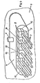
- the piece of material made of viscose (QuellmoduI1) has approximately the shape and size drawn in full lines in FIG.
- the base material of this material was pressed during manufacture (possibly in two planes lying perpendicular to each other with different pressures). After the piece of material has been moistened with a liquid, it expands to different extents in the directions indicated by arrows and can assume the final form 2 shown in dashed lines.
- Pieces of material in the original form (hereinafter referred to as source modules) are used for packaging the end walls of cable bushings, as are described below with reference to FIGS. 2 and 3.
- the source module 1 shown in FIG. 1 can have comb-like incisions which are not shown in the drawing.
- 3 denotes an interface on board a ship.
- a rounded hollow body 4 is firmly connected to the parting surface 3 as a passage by means of welding 5.
- a filler neck 6 is arranged, which serves to fill the potting compound that fills the interior of the implementation after closing the end walls of the implementation.
- Another nozzle is on the same surface behind the separating surface as a vent.
- the passage (hollow body 4) leads through the one space to be laid in the neighboring cables and lines. They are provided with the reference number 7. To prevent the liquid casting compound from flowing out, the end walls must be carefully closed.
- the end wall After the cellular structure of the end wall has been completed, it is sprayed with a liquid which swells the swelling modules and thus closes the end wall; as shown in Figure 3. Using a special liquid, such as silica brine, the end wall becomes fireproof at the same time. The swelling proceeds very quickly and forms a securely closed end wall in a few minutes. If the opposite end wall is closed in the same way, the potting compound can be poured in through the filler neck 6 and thus the interior of the cable bushing (hollow body 4) can be filled in without the risk; that the potting compound emerges from the end walls.
- a liquid such as silica brine
- a cable bushing (hollow body 4) with an oval cross section is passed through a separating surface 3. Both parts are connected by a weld 5 water and gas tight. The cables and lines 7 are passed through the interior of the cable bushing.
- the cables 7 are stored in molded parts 8 made of absorbent material. These material parts can have an approximately square cross-section. They are provided with a bore 9 which is adapted to the diameter of the cable and with a longitudinal slot 10 through which the cable can be conveniently inserted into the molded part.
- the gaps 11, 12 and 13 remaining in the end face after all the cables have been inserted into the molded parts are filled by pieces of material which are adapted to the shape. If all cavities and gaps, including those between the molded parts 8, are now filled, the entire material package is under a bit of tension.
- the liquid refractory casting compound can be poured through the filler neck 6 into the interior of the cable duct (cavity 4). The casting compound quickly penetrates the bulky, absorbent material and solidifies before the outer layer of the molded material is soaked. After filling the cable duct and curing the casting compound, it is so intimately connected to the walls of the duct and the sheaths of the cables and lines that a gas- and watertight and fireproof cable duct is achieved.
- the end of the cable bushing In order to ensure and increase the safety and tightness of the end of the cable bushing with the aid of the material parts, it can be useful to store a component of the casting compound in the material for closing the end walls of the bushings during its manufacture, in order to fill in the hollow body bring about a rapid solidification of the front wall of the liquid casting compound.
- the surface of the end walls can be pretreated with the liquid component of the casting compound. This pretreatment of the end walls has the advantage that the absorbent and swellable material expands in such a way that it seals even the smallest openings between the cables. This effect is so effective that it can be filled with the liquid casting compound immediately after the pretreatment.
- the end walls of the hollow body 4 consist of individual pieces of an absorbent and swellable material, which are inserted so that all cables and lines 7 are adhered to each other and against the hollow body 4 at a distance. After moistening the pieces with a liquid, all remaining openings within the end wall are closed, using preferred swelling directions, and then the passage (hollow body 4) is filled with the casting compound.
- the implementation produced by the method is preferably used in shipbuilding and offers compared to all conventional Ver drive great economic and practical advantages.
Landscapes
- Engineering & Computer Science (AREA)
- General Engineering & Computer Science (AREA)
- Architecture (AREA)
- Civil Engineering (AREA)
- Structural Engineering (AREA)
- Mechanical Engineering (AREA)
- Installation Of Indoor Wiring (AREA)
- Laying Of Electric Cables Or Lines Outside (AREA)
- Catching Or Destruction (AREA)
- Sealing Material Composition (AREA)
Abstract
Claims (10)
Applications Claiming Priority (8)
| Application Number | Priority Date | Filing Date | Title |
|---|---|---|---|
| DE2829887 | 1978-07-07 | ||
| DE19782829887 DE2829887C2 (de) | 1978-07-07 | 1978-07-07 | Verfahren zur Herstellung von wasserdichten und feuerfesten Kabeldurchführungen |
| DE2846061 | 1978-10-23 | ||
| DE19782846061 DE2846061C2 (de) | 1978-10-23 | 1978-10-23 | Verfahren zur Herstellung wasserdichter und feuerfester Durchführungen für Kabel |
| DE19792908238 DE2908238C2 (de) | 1979-03-02 | 1979-03-02 | Verfahren zur Herstellung von wasserdichten und feuerfesten Durchführungen für Kabel |
| DE2908238 | 1979-03-02 | ||
| DE19797915639 DE7915639U1 (de) | 1979-05-30 | 1979-05-30 | Vorrichtung zum Verschließen von Hohlkörpern, die als Durchführungen von Kabeln und Leitungen in Trennflächen eingebaut sind |
| DE7915639U | 1979-05-30 |
Publications (2)
| Publication Number | Publication Date |
|---|---|
| EP0016119A1 EP0016119A1 (fr) | 1980-10-01 |
| EP0016119B1 true EP0016119B1 (fr) | 1982-05-19 |
Family
ID=27432323
Family Applications (1)
| Application Number | Title | Priority Date | Filing Date |
|---|---|---|---|
| EP79900822A Expired EP0016119B1 (fr) | 1978-07-07 | 1979-07-04 | Procede de fabrication de douilles de traversee etanches et incombustibles pour cables |
Country Status (11)
| Country | Link |
|---|---|
| EP (1) | EP0016119B1 (fr) |
| JP (1) | JPS6115648B2 (fr) |
| DD (1) | DD144630A5 (fr) |
| FI (1) | FI65873C (fr) |
| GB (1) | GB2038566B (fr) |
| IT (1) | IT1122084B (fr) |
| NO (1) | NO147893C (fr) |
| PL (1) | PL120748B1 (fr) |
| SE (1) | SE417038B (fr) |
| WO (1) | WO1980000205A1 (fr) |
| YU (1) | YU44099B (fr) |
Cited By (1)
| Publication number | Priority date | Publication date | Assignee | Title |
|---|---|---|---|---|
| CN110192055A (zh) * | 2016-12-20 | 2019-08-30 | 洛科威国际有限公司 | 用于在建筑物的墙壁、天花板或地板中的孔径中提供无火险密封的系统,用于无火险密封系统的元件,以及用于孔径中的无火险密封的隔板 |
Families Citing this family (3)
| Publication number | Priority date | Publication date | Assignee | Title |
|---|---|---|---|---|
| DE8235062U1 (de) * | 1982-12-14 | 1983-06-09 | Rittal-Werk Rudolf Loh Gmbh & Co Kg, 6348 Herborn | Schaltschrank mit einem in mindestens zwei Teilplatten unterteilten Boden |
| DE3816870C2 (de) * | 1987-06-30 | 1993-09-30 | Heidelberger Druckmasch Ag | Einrichtung zum Durchführen von Kabeln |
| DE4036792C1 (fr) * | 1990-11-19 | 1991-12-19 | Dmt Marinetechnik Gmbh, 2000 Hamburg, De |
Family Cites Families (5)
| Publication number | Priority date | Publication date | Assignee | Title |
|---|---|---|---|---|
| FR1180469A (fr) * | 1956-08-06 | 1959-06-04 | Licentia Gmbh | élément étanche à l'eau sous pression pour le passage des câbles à travers lescloisons dans les navires, ainsi que procédé et dispositif pour sa fabrication |
| AU471908B1 (en) * | 1969-07-28 | 1972-02-03 | Improvements in and relating to sealing means | |
| DE2162251A1 (de) * | 1971-12-15 | 1973-06-20 | Flamex Ltd | Sperrvorrichtung, insbesondere fuer den brandschutz |
| FR2339805A1 (fr) * | 1976-01-28 | 1977-08-26 | Torossian Fernand | Procede et dispositifs pour supprimer des fuites de fluides dans une cavite |
| DE2632325C3 (de) * | 1976-07-17 | 1983-12-29 | Neuwalzwerk Bettermann Ohg, 5750 Menden | Brandschutzeinrichtung für eine Kabeldurchführung |
-
1979
- 1979-06-27 DD DD79213940A patent/DD144630A5/de not_active IP Right Cessation
- 1979-07-04 WO PCT/DE1979/000068 patent/WO1980000205A1/fr unknown
- 1979-07-04 EP EP79900822A patent/EP0016119B1/fr not_active Expired
- 1979-07-04 NO NO792229A patent/NO147893C/no unknown
- 1979-07-04 JP JP54501158A patent/JPS6115648B2/ja not_active Expired
- 1979-07-04 GB GB8007018A patent/GB2038566B/en not_active Expired
- 1979-07-05 YU YU1626/79A patent/YU44099B/xx unknown
- 1979-07-05 FI FI792129A patent/FI65873C/fi not_active IP Right Cessation
- 1979-07-07 PL PL1979216948A patent/PL120748B1/pl unknown
- 1979-07-09 IT IT24211/79A patent/IT1122084B/it active
-
1980
- 1980-03-03 SE SE8001651A patent/SE417038B/sv not_active IP Right Cessation
Cited By (2)
| Publication number | Priority date | Publication date | Assignee | Title |
|---|---|---|---|---|
| CN110192055A (zh) * | 2016-12-20 | 2019-08-30 | 洛科威国际有限公司 | 用于在建筑物的墙壁、天花板或地板中的孔径中提供无火险密封的系统,用于无火险密封系统的元件,以及用于孔径中的无火险密封的隔板 |
| CN110192055B (zh) * | 2016-12-20 | 2021-12-03 | 洛科威国际有限公司 | 用于提供无火险密封的系统,用于该系统的元件,以及用于孔径中的无火险密封的隔板 |
Also Published As
| Publication number | Publication date |
|---|---|
| EP0016119A1 (fr) | 1980-10-01 |
| FI65873B (fi) | 1984-03-30 |
| NO792229L (no) | 1980-01-08 |
| GB2038566B (en) | 1982-10-20 |
| FI792129A (fi) | 1980-01-08 |
| SE417038B (sv) | 1981-02-16 |
| DD144630A5 (de) | 1980-10-22 |
| YU162679A (en) | 1982-06-30 |
| SE8001651L (sv) | 1980-03-03 |
| GB2038566A (en) | 1980-07-23 |
| WO1980000205A1 (fr) | 1980-02-07 |
| YU44099B (en) | 1990-02-28 |
| PL120748B1 (en) | 1982-03-31 |
| NO147893C (no) | 1983-06-29 |
| FI65873C (fi) | 1984-07-10 |
| IT1122084B (it) | 1986-04-23 |
| IT7924211A0 (it) | 1979-07-09 |
| PL216948A1 (fr) | 1980-08-25 |
| NO147893B (no) | 1983-03-21 |
| JPS55500506A (fr) | 1980-08-07 |
| JPS6115648B2 (fr) | 1986-04-25 |
Similar Documents
| Publication | Publication Date | Title |
|---|---|---|
| DE69201040T2 (de) | Feuergeschützte Anordnung und Verfahren zum Einführen wenigstens eines Kabels, Rohres oder dergleichen durch eine Wandöffnung; feuergeschützte Anordnung und Verfahren zum Schutz vor Feuerausbreitung entlang einer Wandöffnung. | |
| DE4036792C1 (fr) | ||
| DE8018534U1 (de) | Kabeldurchführung | |
| DE3923197A1 (de) | Kabeldurchfuehrung | |
| EP0016119B1 (fr) | Procede de fabrication de douilles de traversee etanches et incombustibles pour cables | |
| DE2829887C2 (de) | Verfahren zur Herstellung von wasserdichten und feuerfesten Kabeldurchführungen | |
| DE1059527B (de) | Kabelmuffe aus einem aushaertenden Giessharz fuer unter Gasinnendruck stehende mehradrige Fernmeldekabel mit kunststoffisolierten Adern und mit einem insbesondere aus Kunststoff bestehenden Kabelmantel | |
| DE1054527B (de) | Verfahren zur Herstellung einer Kabelmuffe ohne Metallgehaeuse und ohne vorgeformte Huelle | |
| DE3307213A1 (de) | Vorrichtung zum fuellen eines nachrichtenkabels | |
| DE2727996B1 (de) | Verfahren zur Herstellung von Kabeldurchfuehrungen und Einrichtungen zu dessen Durchfuehrung | |
| DE2908238C2 (de) | Verfahren zur Herstellung von wasserdichten und feuerfesten Durchführungen für Kabel | |
| DE2727996C3 (fr) | ||
| DE7915639U1 (de) | Vorrichtung zum Verschließen von Hohlkörpern, die als Durchführungen von Kabeln und Leitungen in Trennflächen eingebaut sind | |
| DE3822543C2 (de) | Verfahren zum Herstellen eines gefüllten Kabels | |
| DE3404487A1 (de) | Verfahren zum herstellen einer fuellmasse fuer laengswasserdichte elektrische und/oder optische kabel | |
| DE3139599C2 (de) | Verfahren zur Herstellung von feuerfesten Kabel- und Leitungsdurchführungen | |
| DE1690389A1 (de) | Verfahren zum Herstellen einer Kabelverbindungsmuffe | |
| DE1116384B (de) | Verfahren zum Herstellen einer dichten Verbindung von Polyvinylchloridrohren mit Teilen aus Polyvinylchlorid | |
| DE2328633A1 (de) | Verfahren zur herstellung einer gassperre in der muffe eines fernsprechkabels | |
| DE3126602C2 (de) | Verbindungsgehäuse zwischen einem Behälter für elektrische Anlagen und einer unter Gasüberdruck stehenden Kabelanlage | |
| DE19503705C1 (de) | Vorrichtung zur Durchführung eines Rohres durch einen Randwall einer Deponie | |
| DE69608379T2 (de) | Verfahren zum Verbinden eines Abzweigrohrs an eine Hauptleitung | |
| DE1765348B2 (de) | Verfahren zum abdichten von kabeln gegen laengswasser | |
| DE1640722A1 (de) | Verfahren zur Laengsabdichtung von vieladrigen Nachrichtenkabeln | |
| DE2414112A1 (de) | Dichte wanddurchfuehrung fuer kabel, leitungen oder dergl. |
Legal Events
| Date | Code | Title | Description |
|---|---|---|---|
| PUAI | Public reference made under article 153(3) epc to a published international application that has entered the european phase |
Free format text: ORIGINAL CODE: 0009012 |
|
| 17P | Request for examination filed | ||
| AK | Designated contracting states |
Designated state(s): FR |
|
| GRAA | (expected) grant |
Free format text: ORIGINAL CODE: 0009210 |
|
| AK | Designated contracting states |
Designated state(s): FR |
|
| PGFP | Annual fee paid to national office [announced via postgrant information from national office to epo] |
Ref country code: FR Payment date: 19920817 Year of fee payment: 14 |
|
| PG25 | Lapsed in a contracting state [announced via postgrant information from national office to epo] |
Ref country code: FR Effective date: 19940331 |
|
| REG | Reference to a national code |
Ref country code: FR Ref legal event code: ST |
|
| PLBE | No opposition filed within time limit |
Free format text: ORIGINAL CODE: 0009261 |
|
| STAA | Information on the status of an ep patent application or granted ep patent |
Free format text: STATUS: NO OPPOSITION FILED WITHIN TIME LIMIT |