EP0016119B1 - Process for manufacturing tight and non inflammable traverse sleeves for cables - Google Patents
Process for manufacturing tight and non inflammable traverse sleeves for cables Download PDFInfo
- Publication number
- EP0016119B1 EP0016119B1 EP79900822A EP79900822A EP0016119B1 EP 0016119 B1 EP0016119 B1 EP 0016119B1 EP 79900822 A EP79900822 A EP 79900822A EP 79900822 A EP79900822 A EP 79900822A EP 0016119 B1 EP0016119 B1 EP 0016119B1
- Authority
- EP
- European Patent Office
- Prior art keywords
- cables
- process according
- hollow body
- liquid
- end walls
- Prior art date
- Legal status (The legal status is an assumption and is not a legal conclusion. Google has not performed a legal analysis and makes no representation as to the accuracy of the status listed.)
- Expired
Links
Images

Classifications
-
- H—ELECTRICITY
- H02—GENERATION; CONVERSION OR DISTRIBUTION OF ELECTRIC POWER
- H02G—INSTALLATION OF ELECTRIC CABLES OR LINES, OR OF COMBINED OPTICAL AND ELECTRIC CABLES OR LINES
- H02G3/00—Installations of electric cables or lines or protective tubing therefor in or on buildings, equivalent structures or vehicles
- H02G3/22—Installations of cables or lines through walls, floors or ceilings, e.g. into buildings
-
- F—MECHANICAL ENGINEERING; LIGHTING; HEATING; WEAPONS; BLASTING
- F16—ENGINEERING ELEMENTS AND UNITS; GENERAL MEASURES FOR PRODUCING AND MAINTAINING EFFECTIVE FUNCTIONING OF MACHINES OR INSTALLATIONS; THERMAL INSULATION IN GENERAL
- F16L—PIPES; JOINTS OR FITTINGS FOR PIPES; SUPPORTS FOR PIPES, CABLES OR PROTECTIVE TUBING; MEANS FOR THERMAL INSULATION IN GENERAL
- F16L5/00—Devices for use where pipes, cables or protective tubing pass through walls or partitions
- F16L5/02—Sealing
- F16L5/14—Sealing for double-walled or multi-channel pipes
Definitions
- the invention relates to a method for producing watertight and refractory bushings for cables through ceilings and walls using a hollow body of predetermined length, which is filled with a hardenable casting compound after pulling through all the cables.
- an absorbent and swellable material is used to construct the end walls of the hollow body, with which the cables are enclosed and kept at a distance from one another and against the hollow body, and that the outer surfaces of the end walls are filled before filling of the hollow body with the casting compound are pretreated with a liquid which, in addition to a rapid swelling effect, also causes the material to solidify.
- the advantages of the method according to the invention are, in particular, that no sealing compound is required in relation to the proposed cable bushing in order to adequately seal the end faces of the bushing.
- the combination of the absorbent and swellable material and the refractory casting compound achieves both a sealed and a refractory closure of the bushing at the same time.
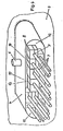
- the piece of material made of viscose (QuellmoduI1) has approximately the shape and size drawn in full lines in FIG.
- the base material of this material was pressed during manufacture (possibly in two planes lying perpendicular to each other with different pressures). After the piece of material has been moistened with a liquid, it expands to different extents in the directions indicated by arrows and can assume the final form 2 shown in dashed lines.
- Pieces of material in the original form (hereinafter referred to as source modules) are used for packaging the end walls of cable bushings, as are described below with reference to FIGS. 2 and 3.
- the source module 1 shown in FIG. 1 can have comb-like incisions which are not shown in the drawing.
- 3 denotes an interface on board a ship.
- a rounded hollow body 4 is firmly connected to the parting surface 3 as a passage by means of welding 5.
- a filler neck 6 is arranged, which serves to fill the potting compound that fills the interior of the implementation after closing the end walls of the implementation.
- Another nozzle is on the same surface behind the separating surface as a vent.
- the passage (hollow body 4) leads through the one space to be laid in the neighboring cables and lines. They are provided with the reference number 7. To prevent the liquid casting compound from flowing out, the end walls must be carefully closed.
- the end wall After the cellular structure of the end wall has been completed, it is sprayed with a liquid which swells the swelling modules and thus closes the end wall; as shown in Figure 3. Using a special liquid, such as silica brine, the end wall becomes fireproof at the same time. The swelling proceeds very quickly and forms a securely closed end wall in a few minutes. If the opposite end wall is closed in the same way, the potting compound can be poured in through the filler neck 6 and thus the interior of the cable bushing (hollow body 4) can be filled in without the risk; that the potting compound emerges from the end walls.
- a liquid such as silica brine
- a cable bushing (hollow body 4) with an oval cross section is passed through a separating surface 3. Both parts are connected by a weld 5 water and gas tight. The cables and lines 7 are passed through the interior of the cable bushing.
- the cables 7 are stored in molded parts 8 made of absorbent material. These material parts can have an approximately square cross-section. They are provided with a bore 9 which is adapted to the diameter of the cable and with a longitudinal slot 10 through which the cable can be conveniently inserted into the molded part.
- the gaps 11, 12 and 13 remaining in the end face after all the cables have been inserted into the molded parts are filled by pieces of material which are adapted to the shape. If all cavities and gaps, including those between the molded parts 8, are now filled, the entire material package is under a bit of tension.
- the liquid refractory casting compound can be poured through the filler neck 6 into the interior of the cable duct (cavity 4). The casting compound quickly penetrates the bulky, absorbent material and solidifies before the outer layer of the molded material is soaked. After filling the cable duct and curing the casting compound, it is so intimately connected to the walls of the duct and the sheaths of the cables and lines that a gas- and watertight and fireproof cable duct is achieved.
- the end of the cable bushing In order to ensure and increase the safety and tightness of the end of the cable bushing with the aid of the material parts, it can be useful to store a component of the casting compound in the material for closing the end walls of the bushings during its manufacture, in order to fill in the hollow body bring about a rapid solidification of the front wall of the liquid casting compound.
- the surface of the end walls can be pretreated with the liquid component of the casting compound. This pretreatment of the end walls has the advantage that the absorbent and swellable material expands in such a way that it seals even the smallest openings between the cables. This effect is so effective that it can be filled with the liquid casting compound immediately after the pretreatment.
- the end walls of the hollow body 4 consist of individual pieces of an absorbent and swellable material, which are inserted so that all cables and lines 7 are adhered to each other and against the hollow body 4 at a distance. After moistening the pieces with a liquid, all remaining openings within the end wall are closed, using preferred swelling directions, and then the passage (hollow body 4) is filled with the casting compound.
- the implementation produced by the method is preferably used in shipbuilding and offers compared to all conventional Ver drive great economic and practical advantages.
Abstract
Description
Die Erfindung bezieht sich auf ein Verfahren zur Herstellung wasserdichter und feuerfester Durchführungen für Kabel durch Decken und Wände unter Verwendung eines Hohlkörpers vorbestimmter Länge, der nach Durchziehen aller Kabel mit einer aushärtbaren Gießmasse ausgefüllt wird.The invention relates to a method for producing watertight and refractory bushings for cables through ceilings and walls using a hollow body of predetermined length, which is filled with a hardenable casting compound after pulling through all the cables.
Es sind zur Durchführung von Kabeln und Leitungen durch Decken und Wände von Gebäuden und an Bord von Schiffen Einrichtungen bekannt, die aus einem Kabelkasten bestehen, durch den die Kabel hindurchgezogen werden. Nach dem Durchziehen sämtlicher Kabel durch den Kabelkasten, der einen rechteckigen oder runden Querschnitt besitzen kann, werden dessen Stirnflächen mit einer Dichtmasse verschlossen und durch auf der Oberfläche befindliche Einfüllstutzen flüssiges aushärtbäres Gießharz in das Innere des Kabelkastens gegossen, bis dieser vollständig ausgefüllt ist. Beispielsweise wird auf das Prospektblatt der AEG mit dem Titel « Schottdurchführungen » mit der Nummer 0806.611 E 23N 1165 hingewiesen.Devices are known for the passage of cables and lines through ceilings and walls of buildings and on board ships, which consist of a cable box through which the cables are pulled. After pulling all the cables through the cable box, which can have a rectangular or round cross-section, its end faces are closed with a sealing compound and liquid hardenable resin is poured into the interior of the cable box through fillers on the surface until it is completely filled. For example, reference is made to the AEG brochure entitled “Bulkhead Bushings” with the number 0806.611 E 23N 1165.
Ein Mangel dieser an sich in der Praxis bewährten Kabeldurchführung besteht darin, daß die Dichtmasse nicht so in alle Räume zwischen den einzelnen Kabeln eingebracht werden kann, daß nicht doch ein Teil des sehr flüssigen Gießharzes vor dem Aushärten durch die Zwischenräume nach außen abfließt.A deficiency of this cable bushing, which has proven itself in practice, is that the sealing compound cannot be introduced into all the spaces between the individual cables in such a way that a part of the very liquid casting resin does not flow out through the spaces before curing.
Um diesen Mangel zu beheben, ist bereits vorgeschlagen worden, vergleiche DE-AS 27 27996, unmittelbar vor den Stirnflächen der Wanddurchführung jedes Kabel mit einem Abstandsstück aus verformbarem Schaumstoff zu umgeben, dieses so gebildete Paket mittels einer Spanneinrichtung so zusammenzupressen, daß die Hohlräume zwischen den Kabeln dicht verschlossen sind. Die Stirnflächen der Durchführung werden in bekannter Weise mit der Dichtmasse verschlossen. Wenn auch mit dieser Durchführung das Ausfließen des Gießharzes verhindert werden kann, so hat sich bei den oft beschränkten Platzverhältnissen an Bord von Schiffen die Benutzung des Spannwerkzeuges als außerordentlich schwierig erwiesen.In order to remedy this deficiency, it has already been proposed, compare DE-AS 27 27996 to surround each cable with a spacer made of deformable foam directly in front of the end faces of the wall bushing, to compress this package thus formed by means of a tensioning device so that the cavities between the Cables are tightly closed. The end faces of the bushing are closed with the sealing compound in a known manner. Even if this implementation prevents the pouring of the casting resin, the use of the tensioning tool has proven to be extremely difficult given the often limited space on board ships.
Es ist daher Aufgabe der Erfindung, ein Verfahren anzugeben, mit dem die vorbeschriebenen Nachteile bei Kabeldurchführungen der genannten Art vermieden werden und mit dem wasser-, gasdichte und feuerfeste Durchführungen ohne besondere Werkzeuge rasch hergestellt werden können.It is therefore an object of the invention to provide a method with which the above-described disadvantages in cable bushings of the type mentioned are avoided and with which water, gas-tight and fireproof bushings can be produced quickly without special tools.
Zur Lösung dieser Aufgabe wird erffndungsgemäß vorgeschlagen, daß zum Aufbau der Stirnwände des Hohlkörpers ein saug- und quellfähiger Werkstoff verwendet wird, mit dem die Kabel umschlossen und auf Abstand gegeneinander und gegen den Hohlkörper gehalten werden, und daß die äußeren Flächen der Stirnwände vor dem Auffüllen des Hohlkörpers mit der Gießmasse mit einer Flüssigkeit vorbehandelt werden, mit der außer einer raschen Quellwirkung auch eine Verfestigung des Werkstoffes bewirkt wird.To solve this problem, it is proposed according to the invention that an absorbent and swellable material is used to construct the end walls of the hollow body, with which the cables are enclosed and kept at a distance from one another and against the hollow body, and that the outer surfaces of the end walls are filled before filling of the hollow body with the casting compound are pretreated with a liquid which, in addition to a rapid swelling effect, also causes the material to solidify.
Die Vorteile, die das Verfahren nach der Erfindung aufweist, bestehen insbesondere darin, daß gegenüber der vorgeschlagenen Kabeldurchführung keine Dichtungsmasse erforderlich ist, um die Stirnflächen der Durchführung ausreichend abzudichten. Durch die Kombination des saug- und quellfähigen Werkstoffes und der feuerfesten Gießmasse wird gleichzeitig sowohl ein dichter als auch ein feuerfester Abschluß der Durchführung erzielt.The advantages of the method according to the invention are, in particular, that no sealing compound is required in relation to the proposed cable bushing in order to adequately seal the end faces of the bushing. The combination of the absorbent and swellable material and the refractory casting compound achieves both a sealed and a refractory closure of the bushing at the same time.
Neben diesen Vorteilen wird eine wesentliche Material- und Arbeitszeitersparnis, Montagefreundlichkeit und ein geringer technischer Aufwand sowie eine Unabhängigkeit von der Form der Durchführung und der Kabeldurchmesser erreicht.In addition to these advantages, it saves a lot of material and time, is easy to install, requires little technical effort and is independent of the form of the feedthrough and the cable diameter.
In der Zeichnung sind Beispiele für eine Einrichtung zur Durchführung des Verfahrens dargestellt. Es zeigt
Figur 1 ein Werkstoffstück mit den Ausgangs-und Endabmessungen,Figur 2 eine abgerundete Durchführung mit dem Aufbau einer Stirnwand und,- Figur die gleiche Durchführung mit der geschlossenen Stirnwand,
- Figur4 eine Stirnwand aus Formteilen.
- FIG. 1 a piece of material with the initial and final dimensions,
- FIG. 2 shows a rounded bushing with the construction of an end wall, and
- Figure the same implementation with the closed end wall,
- Figure4 an end wall made of molded parts.
Das aus Viskose hergestellte Werkstoffstück (QuellmoduI1) hat etwa die in Figur 1 in vollen Linien gezeichnete Form und Größe. Das Ausgangsmaterial dieses Werkstoffes ist während der Herstellung gepresst worden, (gegebenenfalls in zwei senkrecht zueinander Liegenden Ebenen mit unterschiedlichen Drücken). Nach Befeuchten des Werkstoffstückes mit einer Flüssigkeit dehnt es sich in den mit Pfeilen bezeichneten Richtungen unterschiedlich stark aus und kann etwa die gestrichelt dargestellte endgültige Form 2 einnehmen. Werkstoffstücke in der ursprünglichen Form (nachfolgend Quellmodule genannt) werden zur Verpackung der Stirnwände von Kabeldurchführungen verwendet, wie sie anhand der Figuren 2 und 3 nachfolgend beschrieben werden.The piece of material made of viscose (QuellmoduI1) has approximately the shape and size drawn in full lines in FIG. The base material of this material was pressed during manufacture (possibly in two planes lying perpendicular to each other with different pressures). After the piece of material has been moistened with a liquid, it expands to different extents in the directions indicated by arrows and can assume the
Das in Fig. 1 dargestellte Quellmodul 1 kann kammartige Einschnitte aufweisen, die in der Zeichnung nicht enthalten sind.The
In den Figuren 2 und 3 ist mit 3 eine Trennfläche an Bord eines Schiffes bezeichnet. Mit der Trennfläche 3 ist ein abgerundeter Hohlkörper 4 als Durchführung mittels Schweissung 5 fest verbunden. An der oberen Fläche der Kabeldurchführung ist ein Einfüllstutzen 6 angeordnet, der zum Einfüllen der Vergußmasse dient, die nach Verschließen der Stirnwände der Durchführung das Innere der Durchführung ausfüllt. Ein weiterer Stutzen befindet sich auf derselben Fläche hinter der Trennfläche als Entlüftung.In FIGS. 2 and 3, 3 denotes an interface on board a ship. A rounded
Durch die Durchführung (Hohlkörper 4) sind die von dem einen Raum in den benachbarten zu verlegenden Kabel und Leitungen hindurchgeführt. Sie sind mit den Bezugszeichen 7 versehen. Um ein Ausfließen der flüssigen Gießmasse zu verhindern, müssen die Stirnwände sorgfältig verschlossen werden.The passage (hollow body 4) leads through the one space to be laid in the neighboring cables and lines. They are provided with the reference number 7. To prevent the liquid casting compound from flowing out, the end walls must be carefully closed.
Dies geschieht, indem die Stirnwand mit den Quellmodulen 1, wie in Figur2 dargestellt, zellenförmig um die Kabel von unten nach oben aufgebaut wird. Jedes Kabel und jede Leitung wird durch waagerecht und senkrecht angeordnete Quellmodule 1 umschlossen, deren Quellrichtungen immer quer zur Durchführung (Hohlkörper 4) zeigen. Gleichzeitig sind durch diese Anordnung alle erforderlichen Abstände gewährleistet. Kammartige Quellmodule 1 werden dabei so eingebracht, daß die Zähne in das Innere der Durchführung gerichtet sind. Je nach Größe der zwischen den Kabeln oder zwischen Kabeln und Wandung verbleibenden Öffnungen können auch mehrere Werkstoffstücke nebeneinander oder übereinander gelegt werden.This is done by building up the end wall with the
Nachdem der zellenförmige Aufbau der Stirnwand abgeschlossen ist, wird er mit einer Flüssigkeit bespritzt, die die Quellmodule aufquellen läßt und damit die Stirnwand schließt; wie in Figur 3 dargestellt ist. Unter Verwendung einer besonderen Flüssigkeit, wie beispielsweise Kieselsole, wird die Stirnwand gleichzeitig feuerfest. Das Aufquellen verläuft sehr rasch und bildet in wenigen Minuten eine sicher verschlossene Stirnwand. Wenn die gegenüberliegende Stirnwand in der gleichen Weise verschlossen ist, kann durch den Einfüllstutzen 6 die Vergußmasse eingefüllt und damit der Innenraum der Kabeldurchführung (Hohlkörper4) ausgefüllt werden, ohne daß die-Gefahr besteht; daß die Vergußmasse aus den Stirnwänden austritt.After the cellular structure of the end wall has been completed, it is sprayed with a liquid which swells the swelling modules and thus closes the end wall; as shown in Figure 3. Using a special liquid, such as silica brine, the end wall becomes fireproof at the same time. The swelling proceeds very quickly and forms a securely closed end wall in a few minutes. If the opposite end wall is closed in the same way, the potting compound can be poured in through the
Gemäß Figur4 ist eine Kabeldurchführung (Hohlkörper 4) mit ovalem Querschnitt durch eine Trennfläche3 hindurchgeführt. Beide Teile sind durch eine Schweißung 5 wasser- und gasdicht miteinander verbunden. Durch das Innere der Kabeldurchführung sind die Kabel und Leitungen 7 hindurchgeführt.According to FIG. 4, a cable bushing (hollow body 4) with an oval cross section is passed through a separating
An der Oberfläche der kabeldurchführung befindet sich ein Einfüllstutzerr6 für die flüssige Gießmasse. Auf der Rückseite der Trennfläche 3 ist die Kabeldurchführung in gleicher Weise ausgebildet. In der Ebene der Stirnfläche sind die Kabel und Leitungen 7 in Formteilen 8 aus saugfähigem Wersktoff gelagert. Diese Werkstoffteile können etwa quadratischen Querschnitt aufweisen, Sie sind mit einer Bohrung 9, die an den Durchmesser des Kabels angepasst ist und mit einem Längsschlitz 10 versehen, durch den das Kabel bequem in das Formteil eingelegt werden kann.There is a filler neck6 for the liquid casting compound on the surface of the cable duct. The cable bushing is designed in the same way on the rear of the separating
Die nach Einlegen aller Kabel in die Formteile in der Stirnfläche verbleibenden Lücken 11, 12 und 13 werden durch etwa an die Form angepasste Werkstoffstücke ausgefüllt. Wenn jetzt alle Hohlräume und Lücken, auch zwischen den Formteilen 8, ausgefüllt sind, steht das gesamte Werkstoffpaket etwas unter Spannung. Im Anschluß an diesen Arbeitsgang kann die flüssige feuerfeste Gießmasse durch den Einfüllstutzen 6 in das Innere der Kabeldurchführung (Holraum 4) gegossen werden. Die Gießmasse dringt rasch in den prösen, saugfähigen Werkstoff ein und wird fest, bevor die äußere Schicht der Werkstofformteile getränkt ist. Nach dem Ausfüllen der Kabeldurchführung und dem Aushärten der Gießmasse ist diese so innig mit den Wandungen der Durchführung und den Mänteln der Kabel und Leitungen verbunden, daß eine gas- und wasserdichte sowie feuerfeste Kabeldurchführung erzielt wird.The
Um die Sicherheit und Dichtigkeit des stirnseitigen Abschlusses der Kabeldurchführung mit Hilfe der Werkstoffteile zu gewährleisten und zu erhöhen, kann es sinnvoll sein, in den Werkstoff zum Verschließen der Stirnwände der Durchführungen während seiner Herstellung eine Komponente der Gießmasse einzulagern, um mit dem Auffüllen des Hohlkörpers mit der flüssigen Gießmasse eine rasche Verfestigung der Stirnwand herbeizuführen. Die Oberfläche der Stirnwände können mit der flüssigen Komponente der Gießmasse vorbehandelt werden. Diese Vorbehandlung der Stirnwände hat den Vorteil, daß der saug- und quellfähige Werkstoff sich derart ausdehnt, daß durch ihn auch die kleinsten Öffnungen zwischen den Kabeln abgedichtet werden. Dieser Effekt ist so wirksam, daß unmittelbar nach der Vorbehandlung das Auffüllen der Durchführung mit der flüssigen Gießmasse erfolgen kann.In order to ensure and increase the safety and tightness of the end of the cable bushing with the aid of the material parts, it can be useful to store a component of the casting compound in the material for closing the end walls of the bushings during its manufacture, in order to fill in the hollow body bring about a rapid solidification of the front wall of the liquid casting compound. The surface of the end walls can be pretreated with the liquid component of the casting compound. This pretreatment of the end walls has the advantage that the absorbent and swellable material expands in such a way that it seals even the smallest openings between the cables. This effect is so effective that it can be filled with the liquid casting compound immediately after the pretreatment.
Bei dem Verfahren zum Verschließen von Hohlkörpern, die als Durchführungen von Kabeln und Leitungen in Trennflächen, vorzugsweise Decken und Wände, insbesondere auf Schiffen, eingebaut sind, und zur Aufnahme einer erhärtenden Gießmasse dienen, bestehen die Stirnwände des Hohlkörpers 4 aus einzelnen Stücken eines saug-und quellfähigen Werkstoffes, die so eingefügt sind, daß alle Kabel und Leitungen 7 auf Abstand gegeneinander und gegen den Hohlkörper 4 gehaften werden. Nach Befeuchten der Stücke mit einer Flüssigkeit werden, unter Ausnutzung bevorzugter Quellrichtungen, alle verbliebenen Öffnungen innerhalb der Stirnwand verschlossen, und danach die Durchführung (Hohlkörper 4) mit der Gießmasse ausgefüllt.In the method for closing hollow bodies which are installed as leadthroughs for cables and lines in separating surfaces, preferably ceilings and walls, in particular on ships, and are used to hold a hardening casting compound, the end walls of the
Die nach dem Verfahren hergestellte Durchführung ist vorzugsweise im Schiffbau einsetzbar und bietet gegenüber allen herkömmlichen Verfahren große wirtschaftliche und praktische Vorteile.The implementation produced by the method is preferably used in shipbuilding and offers compared to all conventional Ver drive great economic and practical advantages.
Claims (10)
Applications Claiming Priority (8)
| Application Number | Priority Date | Filing Date | Title |
|---|---|---|---|
| DE2829887 | 1978-07-07 | ||
| DE19782829887 DE2829887C2 (en) | 1978-07-07 | 1978-07-07 | Process for the production of watertight and fireproof cable bushings |
| DE19782846061 DE2846061C2 (en) | 1978-10-23 | 1978-10-23 | Process for the production of watertight and fireproof penetrations for cables |
| DE2846061 | 1978-10-23 | ||
| DE2908238 | 1979-03-02 | ||
| DE19792908238 DE2908238C2 (en) | 1979-03-02 | 1979-03-02 | Process for the production of watertight and fireproof bushings for cables |
| DE19797915639 DE7915639U1 (en) | 1979-05-30 | 1979-05-30 | Device for closing hollow bodies that are built into parting surfaces as feedthroughs for cables and lines |
| DE7915639U | 1979-05-30 |
Publications (2)
| Publication Number | Publication Date |
|---|---|
| EP0016119A1 EP0016119A1 (en) | 1980-10-01 |
| EP0016119B1 true EP0016119B1 (en) | 1982-05-19 |
Family
ID=27432323
Family Applications (1)
| Application Number | Title | Priority Date | Filing Date |
|---|---|---|---|
| EP79900822A Expired EP0016119B1 (en) | 1978-07-07 | 1979-07-04 | Process for manufacturing tight and non inflammable traverse sleeves for cables |
Country Status (11)
| Country | Link |
|---|---|
| EP (1) | EP0016119B1 (en) |
| JP (1) | JPS6115648B2 (en) |
| DD (1) | DD144630A5 (en) |
| FI (1) | FI65873C (en) |
| GB (1) | GB2038566B (en) |
| IT (1) | IT1122084B (en) |
| NO (1) | NO147893C (en) |
| PL (1) | PL120748B1 (en) |
| SE (1) | SE417038B (en) |
| WO (1) | WO1980000205A1 (en) |
| YU (1) | YU44099B (en) |
Cited By (1)
| Publication number | Priority date | Publication date | Assignee | Title |
|---|---|---|---|---|
| CN110192055A (en) * | 2016-12-20 | 2019-08-30 | 洛科威国际有限公司 | For providing the system sealed without fire in the aperture in the wall, ceiling or floor of building, for the element of no fire sealing system, and for the partition without fire sealing in aperture |
Families Citing this family (3)
| Publication number | Priority date | Publication date | Assignee | Title |
|---|---|---|---|---|
| DE8235062U1 (en) * | 1982-12-14 | 1983-06-09 | Rittal-Werk Rudolf Loh Gmbh & Co Kg, 6348 Herborn | Control cabinet with a base divided into at least two sub-panels |
| DE3816870C2 (en) * | 1987-06-30 | 1993-09-30 | Heidelberger Druckmasch Ag | Device for the passage of cables |
| DE4036792C1 (en) * | 1990-11-19 | 1991-12-19 | Dmt Marinetechnik Gmbh, 2000 Hamburg, De |
Family Cites Families (5)
| Publication number | Priority date | Publication date | Assignee | Title |
|---|---|---|---|---|
| FR1180469A (en) * | 1956-08-06 | 1959-06-04 | Licentia Gmbh | waterproof element under pressure for the passage of cables through bulkheads in ships, as well as method and device for its manufacture |
| AU471908B1 (en) * | 1969-07-28 | 1972-02-03 | Improvements in and relating to sealing means | |
| DE2162251A1 (en) * | 1971-12-15 | 1973-06-20 | Flamex Ltd | LOCKING DEVICE, IN PARTICULAR FOR FIRE PROTECTION |
| FR2339805A1 (en) * | 1976-01-28 | 1977-08-26 | Torossian Fernand | Fluid loss esp. bleeding prevention - by spraying an absorbent material which swells on contact with the fluid |
| DE2632325C3 (en) * | 1976-07-17 | 1983-12-29 | Neuwalzwerk Bettermann Ohg, 5750 Menden | Fire protection device for a cable duct |
-
1979
- 1979-06-27 DD DD79213940A patent/DD144630A5/en not_active IP Right Cessation
- 1979-07-04 EP EP79900822A patent/EP0016119B1/en not_active Expired
- 1979-07-04 GB GB8007018A patent/GB2038566B/en not_active Expired
- 1979-07-04 NO NO792229A patent/NO147893C/en unknown
- 1979-07-04 JP JP54501158A patent/JPS6115648B2/ja not_active Expired
- 1979-07-04 WO PCT/DE1979/000068 patent/WO1980000205A1/en unknown
- 1979-07-05 FI FI792129A patent/FI65873C/en not_active IP Right Cessation
- 1979-07-05 YU YU1626/79A patent/YU44099B/en unknown
- 1979-07-07 PL PL1979216948A patent/PL120748B1/en unknown
- 1979-07-09 IT IT24211/79A patent/IT1122084B/en active
-
1980
- 1980-03-03 SE SE8001651A patent/SE417038B/en not_active IP Right Cessation
Cited By (2)
| Publication number | Priority date | Publication date | Assignee | Title |
|---|---|---|---|---|
| CN110192055A (en) * | 2016-12-20 | 2019-08-30 | 洛科威国际有限公司 | For providing the system sealed without fire in the aperture in the wall, ceiling or floor of building, for the element of no fire sealing system, and for the partition without fire sealing in aperture |
| CN110192055B (en) * | 2016-12-20 | 2021-12-03 | 洛科威国际有限公司 | System for providing a fireless seal, element for such a system, and partition for a fireless seal in an aperture |
Also Published As
| Publication number | Publication date |
|---|---|
| FI65873C (en) | 1984-07-10 |
| NO792229L (en) | 1980-01-08 |
| NO147893B (en) | 1983-03-21 |
| IT7924211A0 (en) | 1979-07-09 |
| SE8001651L (en) | 1980-03-03 |
| NO147893C (en) | 1983-06-29 |
| JPS6115648B2 (en) | 1986-04-25 |
| JPS55500506A (en) | 1980-08-07 |
| DD144630A5 (en) | 1980-10-22 |
| YU44099B (en) | 1990-02-28 |
| WO1980000205A1 (en) | 1980-02-07 |
| GB2038566B (en) | 1982-10-20 |
| GB2038566A (en) | 1980-07-23 |
| EP0016119A1 (en) | 1980-10-01 |
| SE417038B (en) | 1981-02-16 |
| IT1122084B (en) | 1986-04-23 |
| PL120748B1 (en) | 1982-03-31 |
| FI65873B (en) | 1984-03-30 |
| FI792129A (en) | 1980-01-08 |
| PL216948A1 (en) | 1980-08-25 |
| YU162679A (en) | 1982-06-30 |
Similar Documents
| Publication | Publication Date | Title |
|---|---|---|
| DE4036792C1 (en) | ||
| DE2401733A1 (en) | METHOD AND DEVICE FOR TRAINING AN IMPLEMENTATION | |
| DE3923197A1 (en) | CABLE GLANCE | |
| EP0016119B1 (en) | Process for manufacturing tight and non inflammable traverse sleeves for cables | |
| DE2829887C2 (en) | Process for the production of watertight and fireproof cable bushings | |
| DE1920637B2 (en) | CABLE JOINT JOINT AND METHOD OF MANUFACTURING IT | |
| DE1059527B (en) | Cable sleeve made of a hardening casting resin for multi-core telecommunication cables under internal gas pressure with plastic-insulated cores and with a cable sheath, in particular made of plastic | |
| DE1054527B (en) | Process for the production of a cable sleeve without a metal housing and without a preformed cover | |
| DE2727996B1 (en) | Process for the production of cable bushings and devices for its implementation | |
| DE2908238C2 (en) | Process for the production of watertight and fireproof bushings for cables | |
| DE2727996C3 (en) | ||
| DE7915639U1 (en) | Device for closing hollow bodies that are built into parting surfaces as feedthroughs for cables and lines | |
| DE3822543C2 (en) | Method of making a filled cable | |
| DE3404487A1 (en) | METHOD FOR PRODUCING A FILLING MEASUREMENT FOR LONG-TERM WATERPROOF ELECTRICAL AND / OR OPTICAL CABLES | |
| DE3139599C2 (en) | Process for the production of fireproof cable and line bushings | |
| DE1690389A1 (en) | Method for making a cable joint | |
| DE1116384B (en) | Method for making a tight connection of polyvinyl chloride pipes with parts made of polyvinyl chloride | |
| DE2328633A1 (en) | METHOD OF MAKING A GAS BARRIER IN THE SOCKET OF A TELEPHONE CABLE | |
| DE3126602C2 (en) | Connection housing between a container for electrical systems and a cable system under excess gas pressure | |
| DE1765348B2 (en) | PROCEDURE FOR SEALING CABLES FROM LONGITUDINAL WATER | |
| DE1640722A1 (en) | Process for the longitudinal sealing of multi-core communication cables | |
| DE2414112A1 (en) | Sealed duct for passing cables through walls - has an end section with removable gland sealed by packing rings | |
| DE19503705C1 (en) | Arrangement for sealed penetration of pipe through plastic film covering landfill | |
| EP4317631A1 (en) | Modular system for making and sealing a conduit feed-through | |
| DE1152734B (en) | Method for producing an anchorage for an armored cable laid in a cable duct near a cable connection point |
Legal Events
| Date | Code | Title | Description |
|---|---|---|---|
| PUAI | Public reference made under article 153(3) epc to a published international application that has entered the european phase |
Free format text: ORIGINAL CODE: 0009012 |
|
| 17P | Request for examination filed | ||
| AK | Designated contracting states |
Designated state(s): FR |
|
| GRAA | (expected) grant |
Free format text: ORIGINAL CODE: 0009210 |
|
| AK | Designated contracting states |
Designated state(s): FR |
|
| PGFP | Annual fee paid to national office [announced via postgrant information from national office to epo] |
Ref country code: FR Payment date: 19920817 Year of fee payment: 14 |
|
| PG25 | Lapsed in a contracting state [announced via postgrant information from national office to epo] |
Ref country code: FR Effective date: 19940331 |
|
| REG | Reference to a national code |
Ref country code: FR Ref legal event code: ST |
|
| PLBE | No opposition filed within time limit |
Free format text: ORIGINAL CODE: 0009261 |
|
| STAA | Information on the status of an ep patent application or granted ep patent |
Free format text: STATUS: NO OPPOSITION FILED WITHIN TIME LIMIT |