EP0014251B1 - Verbindungseinrichtung für Brandmelder - Google Patents
Verbindungseinrichtung für Brandmelder Download PDFInfo
- Publication number
- EP0014251B1 EP0014251B1 EP79105106A EP79105106A EP0014251B1 EP 0014251 B1 EP0014251 B1 EP 0014251B1 EP 79105106 A EP79105106 A EP 79105106A EP 79105106 A EP79105106 A EP 79105106A EP 0014251 B1 EP0014251 B1 EP 0014251B1
- Authority
- EP
- European Patent Office
- Prior art keywords
- fire alarm
- connection
- socket portion
- insert
- alarm insert
- Prior art date
- Legal status (The legal status is an assumption and is not a legal conclusion. Google has not performed a legal analysis and makes no representation as to the accuracy of the status listed.)
- Expired
Links
- 230000008878 coupling Effects 0.000 title 1
- 238000010168 coupling process Methods 0.000 title 1
- 238000005859 coupling reaction Methods 0.000 title 1
- 230000007797 corrosion Effects 0.000 description 3
- 238000005260 corrosion Methods 0.000 description 3
- 239000000428 dust Substances 0.000 description 2
- 238000011109 contamination Methods 0.000 description 1
- 230000006735 deficit Effects 0.000 description 1
- 230000007613 environmental effect Effects 0.000 description 1
- 238000009434 installation Methods 0.000 description 1
- 238000012423 maintenance Methods 0.000 description 1
- 230000007257 malfunction Effects 0.000 description 1
- 230000003287 optical effect Effects 0.000 description 1
- 238000000926 separation method Methods 0.000 description 1
- 239000000779 smoke Substances 0.000 description 1
Images
Classifications
-
- G—PHYSICS
- G08—SIGNALLING
- G08B—SIGNALLING OR CALLING SYSTEMS; ORDER TELEGRAPHS; ALARM SYSTEMS
- G08B17/00—Fire alarms; Alarms responsive to explosion
-
- G—PHYSICS
- G08—SIGNALLING
- G08B—SIGNALLING OR CALLING SYSTEMS; ORDER TELEGRAPHS; ALARM SYSTEMS
- G08B17/00—Fire alarms; Alarms responsive to explosion
- G08B17/10—Actuation by presence of smoke or gases, e.g. automatic alarm devices for analysing flowing fluid materials by the use of optical means
- G08B17/11—Actuation by presence of smoke or gases, e.g. automatic alarm devices for analysing flowing fluid materials by the use of optical means using an ionisation chamber for detecting smoke or gas
- G08B17/113—Constructional details
Definitions
- the invention relates to a connecting device for a fire detector which consists of a base part fastened in the room to be monitored and a detector part which can be connected to it by means of electrical and mechanical connecting elements, at least three connecting elements on the circumference of the base part and grooves having contact springs on the circumference of the base part facing side of the detector insert are arranged.
- the known fire detectors which are constructed as ionization detectors, optical detectors or as heat-sensitive detectors or the like, generally consist of a base part mounted on the ceiling or wall of the room to be monitored and of a detector insert which is inserted into the base part. This detector insert is either connected to the base part by means of fixed terminals or by means of a contact system.
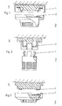
- the various exemplary embodiments are shown in FIGS. 1, 2 and 3 and in CH-PS 355 380 (plug connection according to the electron tube principle), in CH-PS 508 251 (as a bayonet lock), in DE-AS 2E39655 (as a central bayonet lock) and DE-GM 7823178.4 (rotationally symmetrical connector) explained.
- the detectors are often used under very harsh environmental conditions, they are exposed to corrosive vapors, high air humidity, dust deposits or the like. Frequent malfunctions of detectors result from mechanical damage to the contact springs by the service personnel.
- the known fire detectors try to take this problem into account by arranging the movable part of the electrical contact system (contact spring) in the base part 4 and the rigid part of the electrical contact system in the detector insert.
- the contact springs 1 will be bent during the revision, which leads to an impairment of the detector function.
- the invention has for its object to eliminate the disadvantages of the known detectors, that is to create a connecting device of the type mentioned, which makes it possible to remove the detector insert with simple means from the base part, the electrical contacts against accidental contact by the Service personnel are protected and the electrical contact surfaces between the base part and the detector insert are arranged parallel to the axis of the entire detector to reduce the risk of contamination of the contact surfaces from deposits reduce.
- the connecting device which is characterized in that the connecting elements and the grooves come into engagement with one another in such a way that a first partial rotation of the detector insert establishes the mechanical connection and thereby ensures that the electrical connection is prevented during this first partial rotation and that only a subsequent, rectified, second partial rotation of the detector insert establishes the electrical connection between the contact surfaces of the connecting elements and the contact springs arranged parallel to the detector axis.
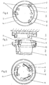
- FIG. 4 shows the top view of the base part 4 of the fire detector.
- Three connecting elements 2 are fastened on the circumference. They form an angle of 120 ° to each other. Of course, four or more connecting elements 2 can also be distributed over the circumference. The distribution does not have to be uniform as shown in Fig.4.
- Each connecting element 2 is bow-shaped. Its part 7, which is arranged radially to the axis of the base part 4, carries the contact surface 6, on which the contact spring 1 arranged in the detector insert 3 comes to rest. This is shown in broken lines in FIG. 4 and will be explained in more detail later with reference to the FIG. In the bottom of the base part 4, fastening holes are provided, which are drawn with dashed lines.
- the connecting elements 2 are arranged between the outer edge 13 and the inner edge 14. Both edges are integrated with the bottom of the base part 4.
- the inner edge 14 contains recesses 12 which form part of the mechanical coding device. The purpose of this coding device is that the detector insert 3 and base part 4 always come into engagement in the correct position. This prevents incorrect electrical contact, which can damage the electrical equipment not only of the fire detector, but also of the control center.
- FIG. 5 shows a sectional view of the base part 4, which is attached to the ceiling or on the wall of the room to be monitored.
- the individual parts have the same reference numerals as described in connection with FIG. 4.
- FIG. 5 shows a partial sectional view of the detector insert 3.
- This detector insert 3 contains the actual detector part in its housing 15, which, however, is not shown.
- the grooves 8 which are distributed in the same number and at the same distance over the circumference as there are connecting elements 2 in the base part.
- the upper part of the detector insert 3 contains a part 11 of the mechanical coding device which, in cooperation with the recesses 12 (FIG. 4), produces the coding.
- the outer wall of the grooves 8 has an edge 5 which, in cooperation with the radial part 7 of the connecting element 2, results in the mechanical connection between the detector insert 3 and the base part 4.
- 5 shows an alarm indicator 10 in the detector insert 3. This alarm indicator 10 lights up when the detector has responded.
- the alarm indicator 10 represents part of the mechanical coding device.
- the inner edge of the groove 8 is formed so that in the working position between the contact spring 1 and the inner edge of the groove only a narrow gap remains, which is designed so that the contact spring 1 lies flat against the inner edge when on the contact spring 1 acts from the outside a radially directed force without contact between the contact spring 1 and the inner edge of the groove taking place in the working position. This ensures that when you do not want to touch the contact springs 1 by any tools such. B. screwdriver, a plastic deformation of the elastic contact springs 1 is avoided.
- FIG. 6 shows the top view in a partial sectional view of the side of the detector insert 3 which faces the base part 4 and engages with it.
- the contact springs 1 are arranged in the grooves 8.
- the grooves 8 have an outer wall which is so far advanced that only a very small recess 9 makes the connection to the outside.
- the part of the mechanical coding device which has already been discussed in more detail in connection with FIG. 5, is designated by 11.
Landscapes
- Business, Economics & Management (AREA)
- Emergency Management (AREA)
- Physics & Mathematics (AREA)
- General Physics & Mathematics (AREA)
- Chemical & Material Sciences (AREA)
- Analytical Chemistry (AREA)
- Fire Alarms (AREA)
- Fire-Detection Mechanisms (AREA)
- Control Of Motors That Do Not Use Commutators (AREA)
- Coupling Device And Connection With Printed Circuit (AREA)
- Fire-Extinguishing By Fire Departments, And Fire-Extinguishing Equipment And Control Thereof (AREA)
- Emergency Alarm Devices (AREA)
- Connector Housings Or Holding Contact Members (AREA)
- Cigarettes, Filters, And Manufacturing Of Filters (AREA)
- Cable Accessories (AREA)
- Connections Arranged To Contact A Plurality Of Conductors (AREA)
Priority Applications (1)
| Application Number | Priority Date | Filing Date | Title |
|---|---|---|---|
| AT79105106T ATE6101T1 (de) | 1979-01-23 | 1979-12-12 | Verbindungseinrichtung fuer brandmelder. |
Applications Claiming Priority (2)
| Application Number | Priority Date | Filing Date | Title |
|---|---|---|---|
| CH69579A CH635001A5 (de) | 1979-01-23 | 1979-01-23 | Verbindungseinrichtung zur verbindung eines sockelteils mit einem meldereinsatz in einem brandmelder. |
| CH695/79 | 1979-01-23 |
Publications (2)
| Publication Number | Publication Date |
|---|---|
| EP0014251A1 EP0014251A1 (de) | 1980-08-20 |
| EP0014251B1 true EP0014251B1 (de) | 1984-02-01 |
Family
ID=4193000
Family Applications (1)
| Application Number | Title | Priority Date | Filing Date |
|---|---|---|---|
| EP79105106A Expired EP0014251B1 (de) | 1979-01-23 | 1979-12-12 | Verbindungseinrichtung für Brandmelder |
Country Status (11)
| Country | Link |
|---|---|
| US (1) | US4315594A (enExample) |
| EP (1) | EP0014251B1 (enExample) |
| JP (1) | JPS6033512Y2 (enExample) |
| AT (1) | ATE6101T1 (enExample) |
| AU (1) | AU536176B2 (enExample) |
| CA (1) | CA1155196A (enExample) |
| CH (1) | CH635001A5 (enExample) |
| DE (1) | DE2966632D1 (enExample) |
| DK (1) | DK150865C (enExample) |
| ES (1) | ES8102384A1 (enExample) |
| NO (1) | NO150017C (enExample) |
Cited By (1)
| Publication number | Priority date | Publication date | Assignee | Title |
|---|---|---|---|---|
| DE102011083080A1 (de) * | 2011-09-20 | 2013-03-21 | Siemens Aktiengesellschaft | Sockel zur Aufnahme eines Gefahrenmelders |
Families Citing this family (45)
| Publication number | Priority date | Publication date | Assignee | Title |
|---|---|---|---|---|
| DE8231210U1 (de) * | 1982-11-08 | 1983-02-10 | Siemens AG, 1000 Berlin und 8000 München | Adapter fuer automatische brandmelder und adapter mit melderfassung zur montage auf bereits installierte meldersockel |
| AU1893383A (en) * | 1983-03-07 | 1984-09-13 | Emhart Industries Inc. | Mount for fire sensor |
| JPH0426946Y2 (enExample) * | 1986-02-13 | 1992-06-29 | ||
| USD311703S (en) | 1987-05-18 | 1990-10-30 | Pittway Corporation | Smoke detector |
| ATE74678T1 (de) * | 1987-07-14 | 1992-04-15 | Siemens Ag | Optischer rauchmelder. |
| US4829283A (en) * | 1988-01-05 | 1989-05-09 | Pittway Corporation | Supervision arrangement for smoke detectors |
| JP2654073B2 (ja) * | 1988-04-08 | 1997-09-17 | 松下電工株式会社 | 埋込み感知器のベース |
| US5021677A (en) * | 1989-05-02 | 1991-06-04 | Nohmi Bosai Kabushiki Kaisha | Light-scattering-type smoke detector |
| DE9210856U1 (de) * | 1992-08-13 | 1992-10-08 | Siemens AG, 8000 München | Automatischer Brandmelder |
| US5568133A (en) * | 1993-03-19 | 1996-10-22 | Cerberus Ag | Fire alarm |
| CH685409A5 (de) * | 1993-03-19 | 1995-06-30 | Cerberus Ag | Brandmelder. |
| JP3165321B2 (ja) * | 1994-04-14 | 2001-05-14 | ホーチキ株式会社 | 火災感知器及び感知器本体取外し装置 |
| WO1996021208A1 (en) * | 1995-01-04 | 1996-07-11 | Caradon Gent Limited | Improvements in and relating to smoke detectors |
| GB9515380D0 (en) * | 1995-07-27 | 1995-09-27 | Thorn Security | Fire detector positioning |
| DK0772170T3 (da) * | 1995-11-06 | 2001-12-10 | Siemens Building Tech Ag | Automatisk brandalarm |
| DE29609124U1 (de) * | 1996-05-21 | 1996-08-14 | Siemens AG, 80333 München | Automatischer Brandmelder |
| JP3210868B2 (ja) * | 1996-10-11 | 2001-09-25 | ニッタン株式会社 | イオン化式煙感知器 |
| US6133843A (en) * | 1997-04-14 | 2000-10-17 | Pittway Corporation | Modular mounting plate |
| US6838997B1 (en) | 1997-10-17 | 2005-01-04 | Honeywell International, Inc. | Fastenerless connection for output device |
| US6057778A (en) * | 1999-02-04 | 2000-05-02 | Pittway Corporation | Modular interchangeble cover system |
| IES990426A2 (en) * | 1999-04-13 | 2000-11-15 | E I Technology Ltd | An alarm device |
| US6494425B2 (en) * | 2001-02-12 | 2002-12-17 | Napco Security Systems, Inc. | Apparatus and method of installing an alarm sensor to a corner wall |
| DE10242482A1 (de) * | 2002-09-13 | 2004-05-19 | Abb Patent Gmbh | Vorrichtung zur Leitungsführung innerhalb eines Gerätes |
| US7336165B2 (en) * | 2005-01-18 | 2008-02-26 | Fuchs Andrew M | Retrofitting detectors into legacy detector systems |
| GB2426323A (en) * | 2005-05-16 | 2006-11-22 | Fire Fighting Entpr Ltd | Infra-red beam smoke detection system |
| DE102009047358A1 (de) * | 2009-12-01 | 2011-06-09 | Robert Bosch Gmbh | Brandmelder- und/oder -warnvorrichtung |
| DE102014019172B4 (de) | 2014-12-17 | 2023-12-07 | Elmos Semiconductor Se | Vorrichtung und Verfahren zur Unterscheidung von festen Objekten, Kochdunst und Rauch mit einem kompensierenden optischen Messsystem |
| DE102014019773B4 (de) | 2014-12-17 | 2023-12-07 | Elmos Semiconductor Se | Vorrichtung und Verfahren zur Unterscheidung von festen Objekten, Kochdunst und Rauch mittels des Displays eines Mobiltelefons |
| US10600299B2 (en) * | 2015-10-15 | 2020-03-24 | Steven Benjamin Faubion | Smoke detector with removable battery compartment |
| CN107605535A (zh) * | 2017-09-29 | 2018-01-19 | 贵州大学 | 一种便于安装的矿用爆破用烟尘报警器的安装结构 |
| US11181252B2 (en) * | 2018-10-09 | 2021-11-23 | Michael Callahan | Apparatus for steering a light beam using two mirrors having only one mirror moved |
| USD896114S1 (en) | 2018-12-28 | 2020-09-15 | Topcon Positioning Systems, Inc. | Sensor housing |
| USD885867S1 (en) | 2018-12-28 | 2020-06-02 | Topcon Positioning Systems, Inc. | Adaptor |
| USD896665S1 (en) | 2018-12-28 | 2020-09-22 | Topcon Positioning Systems, Inc. | Sensor housing |
| USD896662S1 (en) | 2018-12-28 | 2020-09-22 | Topcon Positioning Systems, Inc. | Sensor housing |
| USD896666S1 (en) | 2018-12-28 | 2020-09-22 | Topcon Positioning Systems, Inc. | Sensor housing |
| USD896664S1 (en) | 2018-12-28 | 2020-09-22 | Topcon Positioning Systems, Inc. | Sensor housing |
| USD896667S1 (en) | 2018-12-28 | 2020-09-22 | Topcon Positioning Systems, Inc. | Sensor housing |
| USD897225S1 (en) | 2018-12-28 | 2020-09-29 | Topcon Positioning Systems, Inc. | Sensor housing |
| USD896668S1 (en) | 2018-12-28 | 2020-09-22 | Topcon Positioning Systems, Inc. | Sensor housing |
| US10781573B2 (en) * | 2018-12-28 | 2020-09-22 | Topcon Positioning Systems, Inc. | Construction machine sensor system |
| USD896669S1 (en) | 2018-12-28 | 2020-09-22 | Topcon Positioning Systems, Inc. | Sensor housing |
| USD896670S1 (en) | 2018-12-28 | 2020-09-22 | Topcon Positioning Systems, Inc. | Sensor housing |
| USD885866S1 (en) | 2018-12-28 | 2020-06-02 | Topcon Positioning Systems, Inc. | Mount base |
| USD896663S1 (en) | 2018-12-28 | 2020-09-22 | Topcon Positioning Systems, Inc. | Sensor housing |
Family Cites Families (8)
| Publication number | Priority date | Publication date | Assignee | Title |
|---|---|---|---|---|
| US1495701A (en) * | 1920-08-19 | 1924-05-27 | Mechanical & Electrical Mfg Co | Rosette for electric wiring |
| US2446971A (en) * | 1945-03-29 | 1948-08-10 | Diedrich J Wittig | Safety plug-in electrical receptacle |
| US2871458A (en) * | 1955-09-27 | 1959-01-27 | Jr Richard A Rybold | Plug and receptacle assembly |
| FR1220035A (fr) * | 1959-05-25 | 1960-05-20 | Silec Liaisons Elec | Raccords électriques |
| US3638170A (en) * | 1970-09-23 | 1972-01-25 | Clyde H Clement | Electrical coupling mechanism |
| US3900795A (en) * | 1973-08-15 | 1975-08-19 | Honeywell Inc | Installation and test tool for ionization smoke detector |
| US3945702A (en) * | 1974-10-15 | 1976-03-23 | Leviton Manufacturing Co., Inc. | Twist-type electrical connector with safety interlock |
| CH633122A5 (en) * | 1978-06-27 | 1982-11-15 | Cerberus Ag | Connecting device on an alarm consisting of a base part and an alarm part with sensor |
-
1979
- 1979-01-23 CH CH69579A patent/CH635001A5/de not_active IP Right Cessation
- 1979-12-12 DE DE7979105106T patent/DE2966632D1/de not_active Expired
- 1979-12-12 EP EP79105106A patent/EP0014251B1/de not_active Expired
- 1979-12-12 AT AT79105106T patent/ATE6101T1/de not_active IP Right Cessation
- 1979-12-28 NO NO794341A patent/NO150017C/no unknown
-
1980
- 1980-01-04 CA CA000343092A patent/CA1155196A/en not_active Expired
- 1980-01-07 US US06/110,006 patent/US4315594A/en not_active Expired - Lifetime
- 1980-01-15 ES ES488357A patent/ES8102384A1/es not_active Expired
- 1980-01-18 JP JP1980003585U patent/JPS6033512Y2/ja not_active Expired
- 1980-01-18 AU AU54716/80A patent/AU536176B2/en not_active Ceased
- 1980-01-18 DK DK022680A patent/DK150865C/da not_active IP Right Cessation
Cited By (2)
| Publication number | Priority date | Publication date | Assignee | Title |
|---|---|---|---|---|
| DE102011083080A1 (de) * | 2011-09-20 | 2013-03-21 | Siemens Aktiengesellschaft | Sockel zur Aufnahme eines Gefahrenmelders |
| DE102011083080B4 (de) * | 2011-09-20 | 2016-05-04 | Siemens Schweiz Ag | Sockel zur Aufnahme eines Gefahrenmelders, Gefahrenmelder zum Einsetzen in einen derartigen Sockel sowie Gefahrenmeldeanlage mit einem derartigen Sockel und Gefahrenmelder |
Also Published As
| Publication number | Publication date |
|---|---|
| DE2966632D1 (en) | 1984-03-08 |
| DK22680A (da) | 1980-07-24 |
| US4315594A (en) | 1982-02-16 |
| NO794341L (no) | 1980-07-24 |
| CA1155196A (en) | 1983-10-11 |
| AU5471680A (en) | 1980-07-31 |
| ES488357A0 (es) | 1980-12-16 |
| DK150865B (da) | 1987-07-06 |
| JPS6033512Y2 (ja) | 1985-10-05 |
| ATE6101T1 (de) | 1984-02-15 |
| NO150017C (no) | 1984-08-15 |
| ES8102384A1 (es) | 1980-12-16 |
| JPS55128187U (enExample) | 1980-09-10 |
| CH635001A5 (de) | 1983-03-15 |
| AU536176B2 (en) | 1984-04-19 |
| DK150865C (da) | 1987-12-28 |
| NO150017B (no) | 1984-04-24 |
| EP0014251A1 (de) | 1980-08-20 |
Similar Documents
| Publication | Publication Date | Title |
|---|---|---|
| EP0014251B1 (de) | Verbindungseinrichtung für Brandmelder | |
| CH633122A5 (en) | Connecting device on an alarm consisting of a base part and an alarm part with sensor | |
| DE19513936A1 (de) | Stecker | |
| DE2441013C3 (de) | Verbinderblock fur Hauptverteilerrahmen in Modulausführung | |
| DE4020581A1 (de) | Wasser- und staubdichter drucktastenschalter | |
| DE2917956A1 (de) | Wandanschlussdose | |
| DE4222656C2 (de) | Elektrische Steckdose | |
| DE2448111C3 (de) | Anordnung zum Anschluß elektrischer Leitungen an ein elektrisches Gerät | |
| DE1665895C3 (de) | Kragensteckvorrichtung in runder Form | |
| DE3842205C2 (de) | Gehäuse für den Anschluß von Kommunikationssystemen | |
| EP0418496B1 (de) | Elektrisches Installationsgerät, insbesondere Schutzkontaktsteckdose | |
| EP3454441B1 (de) | Elektrische verbindungsdose | |
| DE102021104244A1 (de) | Elektrische Verbindungsvorrichtung | |
| CH667341A5 (de) | Verbindungseinrichtung fuer melder. | |
| DE29905482U1 (de) | Vorrichtung zur Bestimmung der lagerichtigen Position von genormten Schalter-/Steckdoseneinsätzen in zugeordneten Unterputz-Schalterdosen | |
| DE2829722C2 (de) | Baustein für Fließbilder für Anzeigetafeln u.dgl | |
| DE2400750B2 (de) | Elektrischer Drehschalter mit einer Isolierstoffplatte und zwei Rotoren | |
| DE2500295A1 (de) | Vorrichtung an einer elektrischen apparatedose | |
| DE102020102427B4 (de) | Streustrombrücke und Wasserzähler mit Streustrombrücke | |
| DE3011762C2 (de) | Mehrpolige Kragensteckvorrichtung | |
| DE1919575U (de) | Montageschablone fuer elektrische installationsgeraete. | |
| DE8222551U1 (de) | Steckbarer Klemmensockel für mehrpolige Messerleisten | |
| DE2218435C3 (de) | Verbindungsteil zur Aufnahme der elektrischen Leitungen zwischen zwei Leuchten eines Lichtbandes | |
| EP0111156A1 (de) | Adapter für automatische Brandmelder und Adapter mit Melderfassung zur Montage auf bereits installierte Meldersockel | |
| DE1538309C (de) | Programmierbare Schalttafel |
Legal Events
| Date | Code | Title | Description |
|---|---|---|---|
| PUAI | Public reference made under article 153(3) epc to a published international application that has entered the european phase |
Free format text: ORIGINAL CODE: 0009012 |
|
| AK | Designated contracting states |
Designated state(s): AT BE DE FR GB IT LU NL SE |
|
| 17P | Request for examination filed |
Effective date: 19801120 |
|
| ITF | It: translation for a ep patent filed | ||
| GRAA | (expected) grant |
Free format text: ORIGINAL CODE: 0009210 |
|
| AK | Designated contracting states |
Designated state(s): AT BE DE FR GB IT LU NL SE |
|
| REF | Corresponds to: |
Ref document number: 6101 Country of ref document: AT Date of ref document: 19840215 Kind code of ref document: T |
|
| REF | Corresponds to: |
Ref document number: 2966632 Country of ref document: DE Date of ref document: 19840308 |
|
| ET | Fr: translation filed | ||
| PLBE | No opposition filed within time limit |
Free format text: ORIGINAL CODE: 0009261 |
|
| STAA | Information on the status of an ep patent application or granted ep patent |
Free format text: STATUS: NO OPPOSITION FILED WITHIN TIME LIMIT |
|
| PG25 | Lapsed in a contracting state [announced via postgrant information from national office to epo] |
Ref country code: LU Free format text: LAPSE BECAUSE OF NON-PAYMENT OF DUE FEES Effective date: 19841231 |
|
| PGFP | Annual fee paid to national office [announced via postgrant information from national office to epo] |
Ref country code: BE Payment date: 19841231 Year of fee payment: 6 |
|
| 26N | No opposition filed | ||
| PGFP | Annual fee paid to national office [announced via postgrant information from national office to epo] |
Ref country code: NL Payment date: 19861231 Year of fee payment: 8 |
|
| PG25 | Lapsed in a contracting state [announced via postgrant information from national office to epo] |
Ref country code: BE Effective date: 19871231 |
|
| BERE | Be: lapsed |
Owner name: CERBERUS A.G. Effective date: 19871231 |
|
| PG25 | Lapsed in a contracting state [announced via postgrant information from national office to epo] |
Ref country code: NL Effective date: 19880701 |
|
| NLV4 | Nl: lapsed or anulled due to non-payment of the annual fee | ||
| PGFP | Annual fee paid to national office [announced via postgrant information from national office to epo] |
Ref country code: AT Payment date: 19891108 Year of fee payment: 11 |
|
| PG25 | Lapsed in a contracting state [announced via postgrant information from national office to epo] |
Ref country code: AT Effective date: 19901212 |
|
| PGFP | Annual fee paid to national office [announced via postgrant information from national office to epo] |
Ref country code: FR Payment date: 19911107 Year of fee payment: 13 |
|
| PGFP | Annual fee paid to national office [announced via postgrant information from national office to epo] |
Ref country code: GB Payment date: 19911114 Year of fee payment: 13 |
|
| PGFP | Annual fee paid to national office [announced via postgrant information from national office to epo] |
Ref country code: SE Payment date: 19911120 Year of fee payment: 13 |
|
| PGFP | Annual fee paid to national office [announced via postgrant information from national office to epo] |
Ref country code: DE Payment date: 19911121 Year of fee payment: 13 |
|
| ITTA | It: last paid annual fee | ||
| PG25 | Lapsed in a contracting state [announced via postgrant information from national office to epo] |
Ref country code: GB Effective date: 19921212 |
|
| PG25 | Lapsed in a contracting state [announced via postgrant information from national office to epo] |
Ref country code: SE Effective date: 19921213 |
|
| GBPC | Gb: european patent ceased through non-payment of renewal fee |
Effective date: 19921212 |
|
| PG25 | Lapsed in a contracting state [announced via postgrant information from national office to epo] |
Ref country code: FR Effective date: 19930831 |
|
| PG25 | Lapsed in a contracting state [announced via postgrant information from national office to epo] |
Ref country code: DE Effective date: 19930901 |
|
| REG | Reference to a national code |
Ref country code: FR Ref legal event code: ST |
|
| EUG | Se: european patent has lapsed |
Ref document number: 79105106.3 Effective date: 19930709 |