BR112017010662B1 - Floor panel set with mechanical locking system - Google Patents
Floor panel set with mechanical locking system Download PDFInfo
- Publication number
- BR112017010662B1 BR112017010662B1 BR112017010662-0A BR112017010662A BR112017010662B1 BR 112017010662 B1 BR112017010662 B1 BR 112017010662B1 BR 112017010662 A BR112017010662 A BR 112017010662A BR 112017010662 B1 BR112017010662 B1 BR 112017010662B1
- Authority
- BR
- Brazil
- Prior art keywords
- tongue
- locking
- edge
- flexible tongue
- flexible
- Prior art date
Links
- 238000006073 displacement reaction Methods 0.000 claims abstract description 66
- 238000005452 bending Methods 0.000 claims abstract description 19
- 239000011162 core material Substances 0.000 abstract description 42
- 238000004519 manufacturing process Methods 0.000 abstract description 23
- 210000002105 tongue Anatomy 0.000 description 377
- 239000000463 material Substances 0.000 description 58
- 239000010410 layer Substances 0.000 description 36
- 238000000034 method Methods 0.000 description 26
- 239000000835 fiber Substances 0.000 description 19
- 229920003023 plastic Polymers 0.000 description 17
- 239000004033 plastic Substances 0.000 description 17
- 229920001169 thermoplastic Polymers 0.000 description 15
- 239000004416 thermosoftening plastic Substances 0.000 description 15
- 239000012815 thermoplastic material Substances 0.000 description 10
- 239000004698 Polyethylene Substances 0.000 description 9
- 230000015572 biosynthetic process Effects 0.000 description 9
- 238000009408 flooring Methods 0.000 description 9
- 239000003365 glass fiber Substances 0.000 description 9
- 229920005989 resin Polymers 0.000 description 9
- 239000011347 resin Substances 0.000 description 9
- 230000008901 benefit Effects 0.000 description 8
- 239000000843 powder Substances 0.000 description 8
- 229920002522 Wood fibre Polymers 0.000 description 7
- 239000002025 wood fiber Substances 0.000 description 7
- 239000012792 core layer Substances 0.000 description 6
- 239000000123 paper Substances 0.000 description 6
- 229920001187 thermosetting polymer Polymers 0.000 description 6
- 238000010438 heat treatment Methods 0.000 description 5
- 239000002184 metal Substances 0.000 description 5
- 229910052751 metal Inorganic materials 0.000 description 5
- 239000002344 surface layer Substances 0.000 description 5
- 239000002023 wood Substances 0.000 description 5
- 229920000877 Melamine resin Polymers 0.000 description 4
- 230000006835 compression Effects 0.000 description 4
- 238000007906 compression Methods 0.000 description 4
- 238000005520 cutting process Methods 0.000 description 4
- 238000001746 injection moulding Methods 0.000 description 4
- 229910052500 inorganic mineral Inorganic materials 0.000 description 4
- 238000003780 insertion Methods 0.000 description 4
- 230000037431 insertion Effects 0.000 description 4
- 239000000203 mixture Substances 0.000 description 4
- 230000002787 reinforcement Effects 0.000 description 4
- 230000003014 reinforcing effect Effects 0.000 description 4
- 239000012779 reinforcing material Substances 0.000 description 4
- 239000004743 Polypropylene Substances 0.000 description 3
- 239000000919 ceramic Substances 0.000 description 3
- 238000001816 cooling Methods 0.000 description 3
- 229920003020 cross-linked polyethylene Polymers 0.000 description 3
- 239000004703 cross-linked polyethylene Substances 0.000 description 3
- 239000000945 filler Substances 0.000 description 3
- 238000003475 lamination Methods 0.000 description 3
- 239000011707 mineral Substances 0.000 description 3
- 239000002245 particle Substances 0.000 description 3
- -1 polypropylene Polymers 0.000 description 3
- 239000004800 polyvinyl chloride Substances 0.000 description 3
- 229920000915 polyvinyl chloride Polymers 0.000 description 3
- 230000008569 process Effects 0.000 description 3
- 239000004634 thermosetting polymer Substances 0.000 description 3
- XLYOFNOQVPJJNP-UHFFFAOYSA-N water Substances O XLYOFNOQVPJJNP-UHFFFAOYSA-N 0.000 description 3
- WURBVZBTWMNKQT-UHFFFAOYSA-N 1-(4-chlorophenoxy)-3,3-dimethyl-1-(1,2,4-triazol-1-yl)butan-2-one Chemical compound C1=NC=NN1C(C(=O)C(C)(C)C)OC1=CC=C(Cl)C=C1 WURBVZBTWMNKQT-UHFFFAOYSA-N 0.000 description 2
- 238000010146 3D printing Methods 0.000 description 2
- XEEYBQQBJWHFJM-UHFFFAOYSA-N Iron Chemical compound [Fe] XEEYBQQBJWHFJM-UHFFFAOYSA-N 0.000 description 2
- 230000009471 action Effects 0.000 description 2
- 239000000853 adhesive Substances 0.000 description 2
- 230000001070 adhesive effect Effects 0.000 description 2
- 239000011230 binding agent Substances 0.000 description 2
- 230000008602 contraction Effects 0.000 description 2
- 239000011243 crosslinked material Substances 0.000 description 2
- 238000001125 extrusion Methods 0.000 description 2
- 238000007667 floating Methods 0.000 description 2
- IVJISJACKSSFGE-UHFFFAOYSA-N formaldehyde;1,3,5-triazine-2,4,6-triamine Chemical compound O=C.NC1=NC(N)=NC(N)=N1 IVJISJACKSSFGE-UHFFFAOYSA-N 0.000 description 2
- 238000002347 injection Methods 0.000 description 2
- 239000007924 injection Substances 0.000 description 2
- 238000003754 machining Methods 0.000 description 2
- JDSHMPZPIAZGSV-UHFFFAOYSA-N melamine Chemical compound NC1=NC(N)=NC(N)=N1 JDSHMPZPIAZGSV-UHFFFAOYSA-N 0.000 description 2
- 239000011120 plywood Substances 0.000 description 2
- 229920000573 polyethylene Polymers 0.000 description 2
- 239000004814 polyurethane Substances 0.000 description 2
- 238000003825 pressing Methods 0.000 description 2
- 238000004080 punching Methods 0.000 description 2
- 238000000926 separation method Methods 0.000 description 2
- 239000000758 substrate Substances 0.000 description 2
- KXGFMDJXCMQABM-UHFFFAOYSA-N 2-methoxy-6-methylphenol Chemical compound [CH]OC1=CC=CC([CH])=C1O KXGFMDJXCMQABM-UHFFFAOYSA-N 0.000 description 1
- 229920002748 Basalt fiber Polymers 0.000 description 1
- 229920000049 Carbon (fiber) Polymers 0.000 description 1
- 239000004801 Chlorinated PVC Substances 0.000 description 1
- 240000005561 Musa balbisiana Species 0.000 description 1
- 235000018290 Musa x paradisiaca Nutrition 0.000 description 1
- 229920001807 Urea-formaldehyde Polymers 0.000 description 1
- 229910052782 aluminium Inorganic materials 0.000 description 1
- XAGFODPZIPBFFR-UHFFFAOYSA-N aluminium Chemical compound [Al] XAGFODPZIPBFFR-UHFFFAOYSA-N 0.000 description 1
- 239000004760 aramid Substances 0.000 description 1
- 229920006231 aramid fiber Polymers 0.000 description 1
- 239000004917 carbon fiber Substances 0.000 description 1
- 229910010293 ceramic material Inorganic materials 0.000 description 1
- 230000008859 change Effects 0.000 description 1
- 229920000457 chlorinated polyvinyl chloride Polymers 0.000 description 1
- 239000002131 composite material Substances 0.000 description 1
- 229920006037 cross link polymer Polymers 0.000 description 1
- 238000005034 decoration Methods 0.000 description 1
- 238000013461 design Methods 0.000 description 1
- 229910003460 diamond Inorganic materials 0.000 description 1
- 239000010432 diamond Substances 0.000 description 1
- 238000005553 drilling Methods 0.000 description 1
- 230000000694 effects Effects 0.000 description 1
- 238000005516 engineering process Methods 0.000 description 1
- 239000003000 extruded plastic Substances 0.000 description 1
- 239000004744 fabric Substances 0.000 description 1
- 239000011094 fiberboard Substances 0.000 description 1
- 239000011152 fibreglass Substances 0.000 description 1
- 239000006260 foam Substances 0.000 description 1
- 239000012458 free base Substances 0.000 description 1
- 239000011121 hardwood Substances 0.000 description 1
- 238000009434 installation Methods 0.000 description 1
- 229910052742 iron Inorganic materials 0.000 description 1
- 230000002427 irreversible effect Effects 0.000 description 1
- 238000005304 joining Methods 0.000 description 1
- 239000004922 lacquer Substances 0.000 description 1
- 239000007788 liquid Substances 0.000 description 1
- 229910001004 magnetic alloy Inorganic materials 0.000 description 1
- 238000005259 measurement Methods 0.000 description 1
- 150000002739 metals Chemical class 0.000 description 1
- 238000003801 milling Methods 0.000 description 1
- 239000002557 mineral fiber Substances 0.000 description 1
- 239000012764 mineral filler Substances 0.000 description 1
- TWNQGVIAIRXVLR-UHFFFAOYSA-N oxo(oxoalumanyloxy)alumane Chemical compound O=[Al]O[Al]=O TWNQGVIAIRXVLR-UHFFFAOYSA-N 0.000 description 1
- 229920001568 phenolic resin Polymers 0.000 description 1
- 239000000049 pigment Substances 0.000 description 1
- 239000002985 plastic film Substances 0.000 description 1
- ODGAOXROABLFNM-UHFFFAOYSA-N polynoxylin Chemical compound O=C.NC(N)=O ODGAOXROABLFNM-UHFFFAOYSA-N 0.000 description 1
- 229920001155 polypropylene Polymers 0.000 description 1
- 229920002635 polyurethane Polymers 0.000 description 1
- 238000007639 printing Methods 0.000 description 1
- 230000005855 radiation Effects 0.000 description 1
- 238000004064 recycling Methods 0.000 description 1
- 238000010561 standard procedure Methods 0.000 description 1
- 239000004575 stone Substances 0.000 description 1
- 230000008961 swelling Effects 0.000 description 1
- 230000001360 synchronised effect Effects 0.000 description 1
- 239000004753 textile Substances 0.000 description 1
- 230000007704 transition Effects 0.000 description 1
- 125000000391 vinyl group Chemical group [H]C([*])=C([H])[H] 0.000 description 1
- 229920002554 vinyl polymer Polymers 0.000 description 1
Images


Classifications
-
- E—FIXED CONSTRUCTIONS
- E04—BUILDING
- E04F—FINISHING WORK ON BUILDINGS, e.g. STAIRS, FLOORS
- E04F15/00—Flooring
- E04F15/02—Flooring or floor layers composed of a number of similar elements
- E04F15/02038—Flooring or floor layers composed of a number of similar elements characterised by tongue and groove connections between neighbouring flooring elements
-
- E—FIXED CONSTRUCTIONS
- E04—BUILDING
- E04F—FINISHING WORK ON BUILDINGS, e.g. STAIRS, FLOORS
- E04F15/00—Flooring
- E04F15/02—Flooring or floor layers composed of a number of similar elements
- E04F15/10—Flooring or floor layers composed of a number of similar elements of other materials, e.g. fibrous or chipped materials, organic plastics, magnesite tiles, hardboard, or with a top layer of other materials
- E04F15/102—Flooring or floor layers composed of a number of similar elements of other materials, e.g. fibrous or chipped materials, organic plastics, magnesite tiles, hardboard, or with a top layer of other materials of fibrous or chipped materials, e.g. bonded with synthetic resins
-
- E—FIXED CONSTRUCTIONS
- E04—BUILDING
- E04F—FINISHING WORK ON BUILDINGS, e.g. STAIRS, FLOORS
- E04F15/00—Flooring
- E04F15/02—Flooring or floor layers composed of a number of similar elements
- E04F15/10—Flooring or floor layers composed of a number of similar elements of other materials, e.g. fibrous or chipped materials, organic plastics, magnesite tiles, hardboard, or with a top layer of other materials
- E04F15/107—Flooring or floor layers composed of a number of similar elements of other materials, e.g. fibrous or chipped materials, organic plastics, magnesite tiles, hardboard, or with a top layer of other materials composed of several layers, e.g. sandwich panels
-
- F—MECHANICAL ENGINEERING; LIGHTING; HEATING; WEAPONS; BLASTING
- F16—ENGINEERING ELEMENTS AND UNITS; GENERAL MEASURES FOR PRODUCING AND MAINTAINING EFFECTIVE FUNCTIONING OF MACHINES OR INSTALLATIONS; THERMAL INSULATION IN GENERAL
- F16B—DEVICES FOR FASTENING OR SECURING CONSTRUCTIONAL ELEMENTS OR MACHINE PARTS TOGETHER, e.g. NAILS, BOLTS, CIRCLIPS, CLAMPS, CLIPS OR WEDGES; JOINTS OR JOINTING
- F16B5/00—Joining sheets or plates, e.g. panels, to one another or to strips or bars parallel to them
- F16B5/0004—Joining sheets, plates or panels in abutting relationship
- F16B5/0084—Joining sheets, plates or panels in abutting relationship characterised by particular locking means
- F16B5/0088—Joining sheets, plates or panels in abutting relationship characterised by particular locking means with locking means moving substantially perpendicular to the main plane, e.g. pins, screws
-
- E—FIXED CONSTRUCTIONS
- E04—BUILDING
- E04F—FINISHING WORK ON BUILDINGS, e.g. STAIRS, FLOORS
- E04F2201/00—Joining sheets or plates or panels
- E04F2201/01—Joining sheets, plates or panels with edges in abutting relationship
- E04F2201/0138—Joining sheets, plates or panels with edges in abutting relationship by moving the sheets, plates or panels perpendicular to the main plane
- E04F2201/0146—Joining sheets, plates or panels with edges in abutting relationship by moving the sheets, plates or panels perpendicular to the main plane with snap action of the edge connectors
-
- E—FIXED CONSTRUCTIONS
- E04—BUILDING
- E04F—FINISHING WORK ON BUILDINGS, e.g. STAIRS, FLOORS
- E04F2201/00—Joining sheets or plates or panels
- E04F2201/05—Separate connectors or inserts, e.g. pegs, pins, keys or strips
- E04F2201/0523—Separate tongues; Interlocking keys, e.g. joining mouldings of circular, square or rectangular shape
- E04F2201/0547—Separate tongues; Interlocking keys, e.g. joining mouldings of circular, square or rectangular shape adapted to be moved perpendicular to the joint edge
-
- E—FIXED CONSTRUCTIONS
- E04—BUILDING
- E04F—FINISHING WORK ON BUILDINGS, e.g. STAIRS, FLOORS
- E04F2201/00—Joining sheets or plates or panels
- E04F2201/05—Separate connectors or inserts, e.g. pegs, pins, keys or strips
- E04F2201/0523—Separate tongues; Interlocking keys, e.g. joining mouldings of circular, square or rectangular shape
- E04F2201/0564—Separate tongues; Interlocking keys, e.g. joining mouldings of circular, square or rectangular shape depending on the use of specific materials
- E04F2201/057—Separate tongues; Interlocking keys, e.g. joining mouldings of circular, square or rectangular shape depending on the use of specific materials of wood
-
- E—FIXED CONSTRUCTIONS
- E04—BUILDING
- E04F—FINISHING WORK ON BUILDINGS, e.g. STAIRS, FLOORS
- E04F2201/00—Joining sheets or plates or panels
- E04F2201/05—Separate connectors or inserts, e.g. pegs, pins, keys or strips
- E04F2201/0523—Separate tongues; Interlocking keys, e.g. joining mouldings of circular, square or rectangular shape
- E04F2201/0564—Separate tongues; Interlocking keys, e.g. joining mouldings of circular, square or rectangular shape depending on the use of specific materials
- E04F2201/0582—Separate tongues; Interlocking keys, e.g. joining mouldings of circular, square or rectangular shape depending on the use of specific materials of fibres or chips, e.g. bonded with synthetic resins
-
- E—FIXED CONSTRUCTIONS
- E04—BUILDING
- E04F—FINISHING WORK ON BUILDINGS, e.g. STAIRS, FLOORS
- E04F2201/00—Joining sheets or plates or panels
- E04F2201/05—Separate connectors or inserts, e.g. pegs, pins, keys or strips
- E04F2201/0523—Separate tongues; Interlocking keys, e.g. joining mouldings of circular, square or rectangular shape
- E04F2201/0564—Separate tongues; Interlocking keys, e.g. joining mouldings of circular, square or rectangular shape depending on the use of specific materials
- E04F2201/0588—Separate tongues; Interlocking keys, e.g. joining mouldings of circular, square or rectangular shape depending on the use of specific materials of organic plastics with or without reinforcements or filling materials
Abstract
A presente invenção refere-se a painéis de piso (1, 1'), os quais são providos com um sistema de travamento mecânico que compreende uma lingueta flexível (10) em um sulco de deslocamento (11). A lingueta flexível (10) pode ser formada a partir do material de núcleo (5) dos painéis de piso e ser inserida durante a produção no sulco de deslocamento (11). O sistema de travamento pode ser travado com flexão vertical.The present invention relates to floor panels (1, 1'), which are provided with a mechanical locking system comprising a flexible tongue (10) in a displacement groove (11). The flexible tongue (10) can be formed from the core material (5) of the floor panels and be inserted during production into the displacement groove (11). The locking system can be locked with vertical bending.
Description
[001] A presente descrição refere-se de maneira geral ao campo de sistemas de travamento mecânicos para painéis de piso e painéis de construção. A invenção mostra placas de piso, sistemas de travamento e métodos de produção.[001] The present description generally refers to the field of mechanical locking systems for floor panels and building panels. The invention shows floor boards, locking systems and production methods.
[002] As modalidades da presente invenção são particularmente apropriadas para o uso em pisos flutuantes finos, que são formados por painéis de piso que são unidos mecanicamente com um sistema de travamento de preferência integrado com o painel de piso, isto é montado na fábrica, são compostos de uma ou mais camadas superior de material termoplástico ou termorrígido ou compensado de madeira, um núcleo intermediário de material à base de madeira e material de plástico, e de preferência uma camada de equilíbrio inferior no lado de trás do núcleo. As modalidades da invenção também podem ser usadas para unir painéis de construção que contêm de preferência um material em placa, por exemplo, painéis de parede tetos, os componentes de mobília e similares. Também podem ser usadas para conectar telhas de cerâmica.[002] The embodiments of the present invention are particularly suitable for use in thin floating floors, which are formed by floor panels that are mechanically joined with a locking system preferably integrated with the floor panel, i.e. factory assembled, are composed of one or more top layers of thermoplastic or thermoset material or plywood, an intermediate core of wood-based material and plastics material, and preferably a lower balance layer on the backside of the core. Embodiments of the invention can also be used to join building panels that preferably contain a board material, for example, wall panels, ceilings, furniture components and the like. They can also be used to connect ceramic tiles.
[003] A descrição a seguir da técnica anterior, os problemas de sistemas e objetos e características conhecidos das modalidades da invenção, portanto, como um exemplo não restritivo, são todos focados acima neste campo de aplicação e em particular nos painéis de piso e especialmente em pisos laminados e painéis de piso termoplástico resilientes finos tais como os chamados pisos de vinil luxuosos, em geral conhecidos como LVT, formados como painéis de piso retangulares com bordas longas e curtas destinadas a ser unidas mecanicamente em ambas as bordas longas e curtas.[003] The following description of the prior art, the problems of systems and objects and known features of the embodiments of the invention, therefore, as a non-restrictive example, are all focused above on this field of application and in particular on the floor panels and especially in laminate flooring and thin resilient thermoplastic flooring panels such as so-called luxury vinyl flooring, commonly known as LVT, formed as rectangular floor panels with long and short edges intended to be mechanically joined on both the long and short edges.
[004] As bordas longas e curtas são usadas principalmente para simplificar a descrição das modalidades da invenção. Os painéis podem ser quadrados. Os painéis de piso são produzidos geralmente com a camada de superfície que é virada para baixo a fim de eliminar tolerâncias da espessura do material do núcleo. A maior parte das modalidades é mostrada com a superfície que é virada para cima a fim de simplificar a descrição.[004] The long and short edges are mainly used to simplify the description of the embodiments of the invention. Panels can be square. Floor panels are generally produced with the surface layer facing downwards to eliminate core material thickness tolerances. Most embodiments are shown with the surface facing up to simplify the description.
[005] Deve ser enfatizado que as modalidades da invenção podem ser usadas em qualquer painel de piso em bordas longas e/ou curtas e podem ser combinadas com todos os tipos de sistema de travamento conhecidos em bordas longas ou curtas que travam os painéis na direção horizontal e/ou vertical.[005] It should be emphasized that the embodiments of the invention can be used on any floor panel on long and/or short edges and can be combined with all known types of locking systems on long or short edges that lock the panels in the direction horizontally and/or vertically.
[006] As partes relevantes desta descrição da técnica anterior também fazem parte das modalidades da invenção.[006] The relevant parts of this description of the prior art also form part of the embodiments of the invention.
[007] Vários painéis de piso no mercado são instalados de uma maneira flutuante com sistemas de travamento mecânicos formados em bordas longas e curtas. Esses sistemas compreendem meios de travamento, que travam os painéis horizontal e verticalmente. Os sistemas de travamento mecânicos são formados normalmente mediante a usinagem do núcleo do painel. Alternativamente, as partes do sistema de travamento podem ser formadas por um material separado, por exemplo, um material de alumínio ou de plástico, o qual é integrado com o painel de piso, isto é, unido com o painel de piso em conexão com a sua manufatura.[007] Several floor panels on the market are installed in a floating manner with mechanical locking systems formed into long and short edges. These systems comprise locking means, which lock the panels horizontally and vertically. Mechanical locking systems are normally formed by machining the panel core. Alternatively, the parts of the locking system can be formed of a separate material, for example an aluminum or plastic material, which is integrated with the floor panel, i.e. joined with the floor panel in connection with the its manufacture.
[008] O piso laminado normalmente compreende um núcleo à base de madeira de 6 a 8 milímetros, mm, uma camada de superfície decorativa superior de 0,2 mm de espessura de laminado e uma camada de equilíbrio inferior de 0,1 mm de espessura de laminado, plástico, papel ou um material do gênero. Uma superfície de laminado compreende papel impregnado com melamina. O material mais comum do núcleo é uma placa de fibra com alta densidade e boa estabilidade normalmente chamada HDF - High Density Fibreboard [Chapa de Fibra de Alta Densidade]. O papel impregnado é laminado ao núcleo com calor e pressão. O material de HDF é duro e tem uma baixa flexibilidade especialmente na direção vertical perpendicular à orientação da fibra.[008] Laminate flooring typically comprises a 6 to 8 mm thick wood-based core, a 0.2 mm thick top decorative surface layer of laminate and a 0.1 mm thick bottom balance layer. laminate, plastic, paper or similar material. A laminate surface comprises melamine impregnated paper. The most common core material is a fiberboard with high density and good stability commonly called HDF - High Density Fibreboard. The impregnated paper is laminated to the core with heat and pressure. HDF material is hard and has low flexibility especially in the vertical direction perpendicular to the fiber orientation.
[009] Recentemente, foi apresentado um novo tipo de pisos laminados à base de pó, indicados geralmente como pisos WFF (Wood Fibre Floors [Pisos de Fibra de Madeira). O papel impregnado é substituído por uma mistura em pó seca que compreende fibras de madeira, partículas de melamina, óxido de alumínio e pigmentos. O pó é aplicado sobre um núcleo de HDF e curado sob calor e pressão. De modo geral, HDF de alta qualidade HDF é usado com um elevado teor de resina e baixo inchamento com água. Decorações avançadas podem ser formadas por meio de impressão digital. A tinta à base de água pode ser injetada na superfície superior do pó ou injetada em várias camadas de pó transparentes antes da prensagem de maneira tal que uma cópia 3D muito resistente ao desgaste pode ser obtida. Uma impressão digital com aglutinante e um pó geralmente conhecida como "método BAP" também pode ser usada para criar impressões 3D avançadas. O pó pigmentado, ou a chamada tinta seca, pode ser aglutinado em várias camadas com um padrão de aglutinante digitalmente aplicado que compreende a tinta base sem pigmentos. Uma elevada resistência ao desgaste é usada frequentemente para produzir cópias de pedra e lajotas. Tais pisos de WFF podem ser bastante largos, e o custo de material para o sistema de travamento de borda curta pode ser bastante elevado.[009] Recently, a new type of powder-based laminate flooring was introduced, generally referred to as WFF floors (Wood Fiber Floors). The impregnated paper is replaced by a dry powder mixture comprising wood fibers, melamine particles, aluminum oxide and pigments. The powder is applied over an HDF core and cured under heat and pressure. Generally speaking, high quality HDF HDF is used with a high resin content and low water swelling. Advanced decorations can be formed using digital printing. The water-based ink can be injected onto the top surface of the powder or injected into several layers of clear powder before pressing in such a way that a very wear-resistant 3D copy can be obtained. A fingerprint with binder and powder commonly known as the "BAP method" can also be used to create advanced 3D prints. The pigmented powder, or so-called dry ink, can be bonded in several layers with a digitally applied binder pattern comprising the pigment-free base ink. High wear resistance is often used to produce stone and tile copies. Such WFF floors can be quite wide, and the material cost for the short edge locking system can be quite high.
[0010] O piso de LVT com uma espessura de 3 a 6 mm compreende normalmente uma camada de desgaste transparente que pode ser revestida com radiação ultravioleta, UV, poliuretano curado, PU, laca e uma folha de plástico decorativa sob a folha transparente. A camada de desgaste e a folha decorativa são laminadas a uma ou várias camadas do núcleo que compreendem uma mistura de material termoplástico e cargas minerais. O núcleo de plástico é geralmente mole e muito flexível.[0010] LVT flooring with a thickness of 3 to 6 mm normally comprises a transparent wear layer which can be coated with ultraviolet radiation, UV, cured polyurethane, PU, lacquer and a decorative plastic sheet under the transparent sheet. The wear layer and the decorative sheet are laminated to one or more core layers comprising a mixture of thermoplastic material and mineral fillers. The plastic core is generally soft and very flexible.
[0011] Os pisos de Compósitos de Madeira e Plástico, de modo geralmente indicados como pisos de WPC, são similares aos pisos de LVT. O núcleo compreende um material termorrígido misturado com cargas de fibra de madeira e é geralmente mais forte e muito mais rígido do que o núcleo de LVT à base de mineral.[0011] Wood and Plastic Composite floors, generally referred to as WPC floors, are similar to LVT floors. The core comprises a thermoset material blended with wood fiber fillers and is generally stronger and much stiffer than mineral-based LVT core.
[0012] Material termoplástico, tal como o cloreto de polivinila, PVC, o 0polipropileno, PP, ou o polietileno, PE, pode ser combinado com uma mistura de fibras de madeira e partículas minerais e isso pode prover uma ampla variedade de painéis de piso com densidades e flexibilidades diferentes.[0012] Thermoplastic material, such as polyvinyl chloride, PVC, polypropylene, PP, or polyethylene, PE, can be combined with a mixture of wood fibers and mineral particles and this can provide a wide variety of flooring panels. with different densities and flexibilities.
[0013] O HDF resistente à umidade com um elevado teor de resina, os pisos de LVT e os pisos de WPC compreendem materiais de núcleo mais fortes e mais flexíveis do que os pisos laminados à base de HDF convencionais e são produzidos de modo geral com uma espessura menor.[0013] Moisture resistant HDF with a high resin content, LVT floors and WPC floors comprise stronger and more flexible core materials than conventional HDF-based laminate floors and are generally produced with a smaller thickness.
[0014] Uma espessura mínima em vários dos tipos de piso acima mencionados é requerida principalmente a fim de formar o sistema de travamento. O próprio painel é geralmente forte e flexível, e uma espessura de cerca de 3 a 5 mm em muitas aplicações deve ser suficiente, mas não pode ser usada, uma vez que não é possível formar sistemas de travamento fortes em tais pisos finos.[0014] A minimum thickness in several of the above mentioned floor types is mainly required in order to form the locking system. The panel itself is generally strong and flexible, and a thickness of around 3-5mm in many applications should suffice, but cannot be used, as it is not possible to form strong interlocking systems on such thin floors.
[0015] Os tipos de piso acima mencionados compreendem materiais de núcleo diferentes com flexibilidade, densidade e forças diferentes. Os sistemas de travamento devem ser adaptados a tais propriedades de materiais diferentes a fim de prover uma função de travamento forte e econômica.[0015] The aforementioned floor types comprise different core materials with different flexibility, density and strength. Locking systems must be adapted to such different material properties in order to provide a strong and economical locking function.
[0016] No texto a seguir, a superfície visível do painel de piso instalado é chamada de "lado dianteiro" ou "superfície do piso", ao passo que o lado oposto do painel de piso, que fica voltado para o subpiso, é chamado de "lado traseiro". A borda entre os lados dianteiro e traseiro é chamada de "borda comum". Por "plano horizontal" entende- se um plano que se estende paralelo ao lado dianteiro. As partes superiores imediatamente justapostas de duas bordas comuns adjacentes de dois painéis de piso unidos definem em conjunto um "plano vertical" perpendicular ao plano horizontal. Por "travamento vertical" entende-se o travamento paralelo ao plano vertical. Por "travamento horizontal" entende-se o travamento paralelo ao plano horizontal.[0016] In the following text, the visible surface of the installed floor panel is called the "front side" or "floor surface", while the opposite side of the floor panel, which faces the subfloor, is called "back side". The edge between the front and rear sides is called the "common edge". By "horizontal plane" is meant a plane that extends parallel to the front side. The immediately juxtaposed upper parts of two adjacent common edges of two joined floor panels together define a "vertical plane" perpendicular to the horizontal plane. By "vertical locking" is meant locking parallel to the vertical plane. By "horizontal locking" is meant locking parallel to the horizontal plane.
[0017] Por "para cima" entende-se para o lado dianteiro, por "para baixo" para o lado traseiro, "para dentro" principalmente horizontalmente para uma parte interna e central do painel e "para fora" principalmente horizontalmente afastado da parte central do painel. TÉCNICA RELACIONADA E SEUS PROBLEMAS[0017] By "up" is meant towards the front side, by "down" towards the rear side, "in" mainly horizontally towards an inner and central part of the panel and "outwards" mainly horizontally away from the panel center. RELATED TECHNIQUE AND ITS PROBLEMS
[0018] Para a união mecânica de bordas longas assim como bordas curtas na direção vertical e horizontal perpendicular às bordas, podem ser usados vários métodos. Um dos métodos mais usados é o método de pressão angular. As bordas longas são instaladas por angulação. As bordas curtas são travadas por pressão horizontal. A conexão vertical é geralmente uma lingueta e um sulco e a conexão horizontal é uma tira com um elemento de travamento dentro na borda que coopera com um sulco de travamento na borda adjacente. A compressão é obtida com uma tira flexível.[0018] For mechanical joining of long edges as well as short edges in the vertical and horizontal direction perpendicular to the edges, various methods can be used. One of the most commonly used methods is the angle pressure method. Long edges are installed by angling. The short edges are locked by horizontal pressure. The vertical connection is generally a tongue and groove and the horizontal connection is a strip with a locking element inside at the edge that cooperates with a locking groove at the adjacent edge. Compression is achieved with a flexible strap.
[0019] Sistemas de travamento similares também podem ser produzidos com uma tira rígida e são conectados com um método de angulação-angulação, no qual ambas as bordas curtas e longas são anguladas em uma posição travada.[0019] Similar locking systems can also be produced with a rigid strip and are connected with an angling-angling method, in which both the short and long edges are angled into a locked position.
[0020] Os chamados "sistemas de travamento de flexão para baixo" avançados com uma lingueta separada e flexível nas bordas curtas foram apresentados onde as bordas longas e curtas são travadas com uma única ação de angulação. Um painel de piso desse tipo é apresentado no documento de patente WO 2006/043893. Ele divulga um painel de piso com um sistema de travamento de borda curta que compreende um elemento de travamento que coopera com um sulco de travamento, para travamento horizontal, e um arco flexível formado desse modo chamado de "lingueta banana" que coopera com um sulco da lingueta, para travamento em uma direção vertical. A lingueta em forma de arco flexível é inserida durante a produção em um sulco de deslocamento formado na borda. A lingueta flexão horizontalmente ao longo da borda durante a conexão e torna possível a instalação dos painéis pelo movimento vertical. As bordas longas são conectadas com um movimento de angulação e de tesoura causado pela mesma ação de angulação conecta bordas curtas. Tal travamento é de modo geral indicado como "dobradura vertical".[0020] Advanced so-called "bending-down locking systems" with a separate, flexible tongue on the short edges have been introduced where the long and short edges are locked with a single angling action. Such a floor panel is disclosed in WO 2006/043893. It discloses a floor panel with a short edge locking system comprising a locking element that cooperates with a locking groove, for horizontal locking, and a flexible arch formed in this way called a "banana tongue" that cooperates with a groove. tongue, for locking in a vertical direction. The flexible arc-shaped tongue is inserted during production into an offset groove formed on the edge. The tongue flexes horizontally along the edge during connection and makes it possible to install the panels by vertical movement. Long edges are connected with a angling and scissoring motion caused by the same angling action connects short edges. Such locking is generally referred to as "vertical bending".
[0021] Os painéis de piso similares também são descritos no documento de patente WO 2007/015669. Esse documento provê um sistema de travamento com flexão para baixo com uma lingueta flexível melhorada que é chamada de "lingueta de cerda" que compreende uma borda da lingueta externa retilínea substancialmente sobre todo o comprimento da lingueta. Uma parte interna da lingueta compreende protuberâncias dobráveis que se estendem horizontalmente ao longo da borda da lingueta.[0021] Similar floor panels are also described in WO 2007/015669 patent document. That document provides a downward bending locking system with an improved flexible tongue which is called a "bristle tongue" which comprises a straight outer tongue edge substantially over the entire length of the tongue. An inner part of the tongue comprises bendable protuberances that extend horizontally along the edge of the tongue.
[0022] O documento de patente WO 2013/151493 descreve um sistema de travamento que tem uma lingueta que é formada a partir do material da borda do painel e inserida em um sulco a fim de formar um sistema de travamento de flexão para baixo. Não é descrito como a lingueta deve ser formada a fim obter uma flexibilidade suficiente e como deve ser inserida em um sulco de uma maneira econômica.[0022] Patent document WO 2013/151493 describes a locking system that has a tongue that is formed from the edge material of the panel and inserted into a groove to form a downward bending locking system. It is not described how the tongue must be formed in order to obtain sufficient flexibility and how it must be inserted into a groove in an economical manner.
[0023] A lingueta flexível separada é uma parte vital do sistema de travamento de flexão para baixo. Seria uma vantagem se a lingueta flexível e separada pudesse ser produzida e inserida na borda de uma maneira mais econômica. Também seria vantajoso se a largura e a espessura da lingueta pudessem ser reduzidas, de maneira tal que um sistema de travamento de flexão para baixo possa ser formado em painéis de piso muito finos.[0023] The separate flexible tongue is a vital part of the bend-down locking system. It would be an advantage if the flexible, separate tongue could be produced and inserted into the edge more cost-effectively. It would also be advantageous if the width and thickness of the tongue could be reduced so that a downward bending locking system can be formed in very thin floor panels.
[0024] Um objetivo das modalidades da presente invenção consiste na provisão de um sistema de travamento de flexão para baixo melhorado e mais econômico que compreende uma lingueta flexível para bordas curtas principalmente adjacentes de painéis de piso finos.[0024] An object of embodiments of the present invention is to provide an improved and more cost-effective bend-down locking system comprising a flexible tongue for primarily adjacent short edges of thin floor panels.
[0025] Um primeiro objetivo específico consiste na provisão de uma lingueta flexível separada que é mais compacta e econômica do que as linguetas conhecidas e que é apropriada para o travamento de painéis finos.[0025] A first specific objective is the provision of a separate flexible tongue which is more compact and economical than known tongues and which is suitable for locking thin panels.
[0026] Um segundo objetivo específico consiste na provisão de um sistema de travamento com uma lingueta flexível e dobrável que pode ser formada como um componente simples, retilíneo e em formato de haste.[0026] A second specific objective is the provision of a locking system with a flexible, collapsible tongue that can be formed as a single straight, rod-shaped component.
[0027] Um terceiro objetivo específico consiste na provisão de um método econômico para a formação de uma lingueta flexível avançada a partir de um material de núcleo de um painel de piso e a inserção da lingueta após a formação em um sulco do painel, de preferência na mesma linha de produção.[0027] A third specific objective is the provision of an economical method for forming an advanced flexible tongue from a core material of a floor panel and inserting the tongue after forming into a groove in the panel, preferably on the same production line.
[0028] Os objetivos acima, individual ou coletivamente, da invenção podem ser atingidos por modalidades da invenção.[0028] The above objects, individually or collectively, of the invention can be achieved by embodiments of the invention.
[0029] De acordo com um primeiro aspecto da invenção, um conjunto de painéis de piso essencialmente idênticos é provido com um sistema de travamento mecânico que compreende uma lingueta flexível, o qual é arranjado em um sulco de deslocamento em uma primeira borda de um primeiro painel e em um sulco da lingueta em uma segunda borda de um segundo painel adjacente. A lingueta flexível é configurada para cooperar com o sulco da lingueta para travamento das primeira e segunda bordas em uma direção vertical. O sistema de travamento mecânico também compreende uma tira de travamento na primeira ou na segunda borda, provida com um elemento de travamento configurado para cooperar com um sulco de travamento na outra dentre a primeira ou a segunda borda para travamento em uma direção horizontal. A lingueta flexível é deslocável na direção horizontal no sulco de deslocamento. Uma parte externa da lingueta flexível compreende duas ou mais seções de borda curvas, cada uma das quais compreende uma superfície de deslizamento, a qual é configurada para cooperar com a segunda borda durante o travamento, e uma superfície de travamento que é configurada para travar em e/ou contra o sulco da lingueta. As seções da lingueta são espaçadas entre si em uma direção do comprimento da lingueta flexível que é curva em uma posição travada e em uma posição destravada. Uma primeira distância horizontal, de uma borda superior externa da primeira borda a uma borda externa da lingueta flexível, e uma segunda distância horizontal, da borda superior externa da primeira borda a uma borda interna da lingueta flexível, variam ao longo de um comprimento da lingueta flexível. As seções da lingueta são configuradas para serem pressionadas para dentro durante o travamento pela segunda borda de maneira tal que as seções curvas são pelo menos parcialmente endireitadas e deformadas como seções em forma de haste essencialmente retilíneas com uma largura, que é essencialmente a mesma ao longo essencialmente de todo o comprimento da lingueta flexível e para se mover de volta para as suas posições iniciais em um estágio final do travamento, de maneira tal que as superfícies de travamento sejam inseridas no sulco da lingueta.[0029] According to a first aspect of the invention, a set of essentially identical floor panels is provided with a mechanical locking system comprising a flexible tongue, which is arranged in a displacement groove on a first edge of a first panel and in a tongue groove on a second edge of an adjacent second panel. The flexible tongue is configured to cooperate with the groove of the tongue to lock the first and second edges in a vertical direction. The mechanical locking system also comprises a locking strip on the first or second edge, provided with a locking element configured to cooperate with a locking groove on the other of the first or second edge for locking in a horizontal direction. The flexible tongue is displaceable in the horizontal direction in the displacement groove. An outer portion of the flexible tongue comprises two or more curved edge sections, each of which comprises a sliding surface which is configured to cooperate with the second edge during locking, and a locking surface which is configured to lock in and/or against the tongue groove. The tongue sections are spaced apart in a direction along the length of the flexible tongue which is curved into a locked position and an unlocked position. A first horizontal distance, from an outer upper edge of the first edge to an outer edge of the flexible tongue, and a second horizontal distance, from the upper outer edge of the first edge to an inner edge of the flexible tongue, vary over a length of the tongue. flexible. The tongue sections are configured to be pressed inward during locking by the second edge such that the curved sections are at least partially straightened and deformed as essentially straight rod-shaped sections with a width that is essentially the same along essentially the entire length of the flexible tongue and to move back to their initial positions at a final stage of locking, such that the locking surfaces are inserted into the groove of the tongue.
[0030] As seções curvas podem ser endireitadas e deformadas como seções na forma de haste essencialmente retilínea com uma largura, que é essencialmente a mesma ao longo essencialmente de todo o comprimento da lingueta flexível.[0030] The curved sections can be straightened and deformed as essentially straight rod-shaped sections with a width that is essentially the same along essentially the entire length of the flexible tongue.
[0031] As seções da lingueta podem ser configuradas para oscilar de volta para suas posições iniciais em um estágio final do travamento, de maneira tal que as superfícies de travamento sejam inseridas no sulco da lingueta.[0031] The tongue sections can be configured to swing back to their initial positions at a final stage of locking, such that the locking surfaces are inserted into the groove of the tongue.
[0032] Aqui e a seguir, a expressão "segunda borda do painel" será usada intercambiavelmente com a expressão "segunda borda" ou "borda adjacente", a menos que esteja indicado de alguma outra maneira.[0032] Here and below, the expression "second edge of the panel" will be used interchangeably with the expression "second edge" or "adjacent edge", unless otherwise indicated.
[0033] Por "essencialmente retilínea" entende-se aqui que a seção curva foi endireitada pelo menos em parte como uma seção reta. A título de exemplo, a seção curva pode ser endireitada como uma seção completamente reta. Uma primeira seção curva pode ser endireitada como uma seção reta ao ser endireitada como uma segunda seção curva, em que a primeira e a segunda seções curvas têm uma borda externa convexa ou côncava ao longo da direção do comprimento das primeira e segunda seções curvas. Durante o endireitamento, um ponto da borda externa da borda externa convexa ou côncava da primeira seção curva se move para o sulco de deslocamento, em que o ponto da borda externa é um ponto na primeira seção curva que fica mais distanciado do sulco de deslocamento. Desse modo, o ponto da borda externa da primeira seção curva se move para um ponto da borda externa segunda seção curva que fica consequentemente mais perto do sulco de deslocamento, em que o ponto da borda externa é agora um ponto na segunda seção curva que é o mais distanciado do sulco de deslocamento.[0033] By "essentially straight" it is meant here that the curved section has been straightened at least in part as a straight section. As an example, the curved section can be straightened as a completely straight section. A first curved section can be straightened as a straight section by being straightened as a second curved section, where the first and second curved sections have a convex or concave outside edge along the length direction of the first and second curved sections. During straightening, a point on the outer edge of the convex or concave outer edge of the first curved section moves into the offset groove, where the outer edge point is a point on the first curved section that is furthest from the offset groove. In this way, the point on the outer edge of the first curved section moves to a point on the outer edge of the second curved section which is consequently closer to the displacement groove, where the point on the outer edge is now a point on the second curved section that is furthest from the displacement groove.
[0034] No estágio final de travamento, as seções da lingueta se movem de volta para as suas posições iniciais. Em um primeiro exemplo, as seções da lingueta se movem parcialmente de volta para as suas posições iniciais. Em um segundo exemplo, as seções da lingueta se movem completamente de volta para as suas posições iniciais. Em um terceiro exemplo, algumas seções da lingueta se movem completamente de volta para as suas posições iniciais e algumas seções da lingueta se movem parcialmente de volta para as suas posições iniciais.[0034] In the final locking stage, the pawl sections move back to their initial positions. In a first example, the tongue sections partially move back to their starting positions. In a second example, the tongue sections move completely back to their starting positions. In a third example, some tongue sections move completely back to their home positions and some tongue sections move partially back to their home positions.
[0035] As seções da lingueta podem se mover de volta para as suas posições iniciais ao oscilar de volta.[0035] Tongue sections can move back to their home positions when swinging back.
[0036] A superfície de deslizamento pode ter um formato que corresponde essencialmente a um formato de uma parte de uma parede inferior do sulco da lingueta. Além disso, a superfície de travamento pode ter um formato que corresponde essencialmente a um formato de uma parte de uma parede superior do sulco da lingueta.[0036] The sliding surface may have a shape that essentially corresponds to a shape of a part of a tongue groove bottom wall. Furthermore, the locking surface may have a shape that essentially corresponds to a shape of a part of a top wall of the tongue groove.
[0037] De preferência, a lingueta flexível é arranjada livremente no sulco de deslocamento. Desse modo, nenhuma parte da lingueta flexível é unida ao painel, por exemplo, por um adesivo ou por uma conexão de fricção.[0037] Preferably, the flexible tongue is arranged freely in the displacement groove. In this way, no part of the flexible tongue is joined to the panel, for example, by an adhesive or a friction connection.
[0038] Alternativamente, no entanto, uma ou mais partes da lingueta flexível podem ser unidas ao painel. Por exemplo, uma primeira parte de extremidade longitudinal e/ou uma segunda parte de extremidade longitudinal da lingueta flexível podem ser unidas ao sulco de deslocamento. A fixação da lingueta pode ser provida por meio de um adesivo, um grampo, ou por meio da inserção da mesma em um entalhe provido no painel, tal como no sulco de deslocamento.[0038] Alternatively, however, one or more parts of the flexible tongue may be joined to the panel. For example, a first longitudinal end part and/or a second longitudinal end part of the flexible tongue may be joined to the displacement groove. The fixing of the tongue may be provided by means of an adhesive, a clamp, or by means of inserting it into a notch provided in the panel, such as in the displacement groove.
[0039] A lingueta pode ser unida ao painel por meio de uma conexão de fricção. A conexão de fricção pode ser provida em uma ou mais partes superiores e/ou inferiores da lingueta ao longo de uma direção do comprimento da lingueta.[0039] The tongue can be joined to the panel by means of a friction connection. The friction connection may be provided on one or more upper and/or lower parts of the tongue along a direction along the length of the tongue.
[0040] Em um primeiro exemplo, as seções curvas da borda são essencialmente idênticas. Em um segundo exemplo, as seções curvas da borda são diferentes.[0040] In a first example, the curved edge sections are essentially identical. In a second example, the curved sections of the edge are different.
[0041] A lingueta flexível pode compreender um material de plástico. O material de plástico pode ser um material termoplástico ou um material de plástico termorrígido. Em particular, o material de plástico pode ser um termoplástico reticulado, tal como PE reticulado. Por "termoplástico reticulado" entende-se aqui que pelo menos uma parte do material termoplástico compreende reticulações.[0041] The flexible tongue may comprise a plastic material. The plastic material may be a thermoplastic material or a thermoset plastic material. In particular, the plastics material may be a cross-linked thermoplastic, such as cross-linked PE. By "crosslinked thermoplastic" it is meant herein that at least a part of the thermoplastic material comprises crosslinks.
[0042] A superfície de deslizamento pode ser uma superfície inclinada. A superfície de deslizamento pode ser essencialmente planar. A superfície de deslizamento pode ser dirigida para cima. De acordo com uma modalidade, a superfície de deslizamento forma um ângulo entre 0° e 60° com respeito ao plano vertical.[0042] The sliding surface can be a sloped surface. The slip surface may be essentially planar. The sliding surface can be directed upwards. According to one embodiment, the sliding surface forms an angle between 0° and 60° with respect to the vertical plane.
[0043] A superfície de travamento pode ser uma superfície inclinada. A superfície de travamento pode ser essencialmente planar. A superfície de travamento pode ser dirigida para baixo. De acordo com uma modalidade, a superfície de travamento forma um ângulo entre 0° e 60° com respeito ao plano vertical.[0043] The locking surface may be an inclined surface. The locking surface may be essentially planar. The locking surface can be directed downwards. In one embodiment, the locking surface forms an angle between 0° and 60° with respect to the vertical plane.
[0044] A largura da lingueta flexível pode ser essencialmente a mesma em 90% do comprimento da lingueta flexível. Por "essencialmente a mesma" para uma medição entende-se dentro de ± 10% de outra.[0044] The width of the flexible tongue can be essentially the same over 90% of the length of the flexible tongue. By "essentially the same" for one measurement is meant within ±10% of another.
[0045] A lingueta flexível pode compreender seções da lingueta com seções transversais de maneira tal que a primeira distância horizontal é essencialmente a mesma que a segunda distância horizontal.[0045] The flexible tongue may comprise sections of the tongue with cross-sections such that the first horizontal distance is essentially the same as the second horizontal distance.
[0046] Uma parte maior da lingueta flexível pode compreender seções transversais com uma largura horizontal e uma espessura vertical que são essencialmente as mesmas. Por "parte maior" entende- se pelo menos 50% de um comprimento da lingueta. Nos exemplos, a parte maior pode ser 70%, 80% ou 90% do comprimento da lingueta. Em um exemplo específico, a parte maior pode ser um comprimento inteiro da lingueta.[0046] A larger part of the flexible tongue may comprise cross-sections with a horizontal width and a vertical thickness that are essentially the same. By "major part" is meant at least 50% of a tongue length. In the examples, the longest part can be 70%, 80%, or 90% of the tongue length. In a specific example, the longest part may be an entire length of the tongue.
[0047] A espessura vertical da lingueta flexível pode ser menor do que cerca de 1,5 mm.[0047] The vertical thickness of the flexible tongue can be less than about 1.5 mm.
[0048] Uma lingueta curva com uma seção transversal simples e uma geometria em forma de haste reta na posição interna propicia várias vantagens que podem ser usadas para projetar uma lingueta flexível muito compacta apropriada para travamento de painéis de piso finos. Por um painel de piso fino entende-se aqui que uma espessura do painel fica entre 6 e 10 mm. Um painel de piso muito fino tem uma espessura abaixo de 6 mm, por exemplo, de 3, 4 ou 5 mm.[0048] A curved tongue with a simple cross section and straight rod-shaped geometry in the internal position provides several advantages that can be used to design a very compact flexible tongue suitable for locking thin floor panels. By a thin floor panel it is here understood that a panel thickness is between 6 and 10 mm. A very thin floor panel has a thickness of less than 6 mm, for example 3, 4 or 5 mm.
[0049] De acordo com um segundo aspecto da invenção, um conjunto de painéis de piso essencialmente idênticos é provido com um sistema de travamento mecânico que compreende uma lingueta flexível, o qual é arranjado em um sulco de deslocamento em uma primeira borda de um primeiro painel, e um sulco da lingueta em uma segunda borda de um segundo painel adjacente. A lingueta flexível é configurada para cooperar com o sulco da lingueta para travamento das primeira e segunda bordas em uma direção vertical. A lingueta flexível compreende uma superfície de deslizamento e uma superfície de travamento. O sulco de deslocamento compreende uma cavidade que compreende paredes de cavidade superior, interna e inferior e uma abertura horizontal. O segundo painel de piso compreende uma protuberância que compreende uma borda deslizante, a qual é configurada para cooperar com a superfície de deslizamento durante o travamento e para pressionar e flexionar uma seção flexível da lingueta na cavidade. A seção flexível da lingueta é configurada para se mover de volta para fora, de maneira tal que a superfície de travamento seja inserida no sulco da lingueta.[0049] According to a second aspect of the invention, a set of essentially identical floor panels is provided with a mechanical locking system comprising a flexible tongue, which is arranged in a displacement groove on a first edge of a first panel, and a tongue groove on a second edge of an adjacent second panel. The flexible tongue is configured to cooperate with the groove of the tongue to lock the first and second edges in a vertical direction. The flexible tongue comprises a sliding surface and a locking surface. The displacement groove comprises a cavity comprising upper, inner and lower cavity walls and a horizontal opening. The second floor panel comprises a protrusion comprising a sliding edge which is configured to cooperate with the sliding surface during locking and to press and flex a flexible section of the tongue in the cavity. The flexible section of the tongue is configured to move back out so that the locking surface is inserted into the groove of the tongue.
[0050] As seções da lingueta podem se mover de volta para as suas posições iniciais ao oscilar de volta.[0050] Tongue sections can move back to their home positions when swinging back.
[0051] A parede interna da cavidade pode ser uma superfície curva ou uma superfície planar. As paredes superior, interna e inferior da cavidade podem começar e terminar no sulco de deslocamento ao longo de uma direção do seu comprimento. As paredes superior, interna e inferior da cavidade podem ser paredes superior, interna e inferior contínuas da cavidade, por meio do que as paredes são lisas e conectadas ao sulco de deslocamento por meio de uma transição suave, sem nenhuma interrupção. As paredes contínuas podem ser formadas por meio de uma ferramenta de entalhar ou oscilar rotativa.[0051] The inner wall of the cavity can be a curved surface or a planar surface. The top, inner, and bottom walls of the cavity may start and end in the displacement groove along a direction along its length. The top, inner and bottom walls of the cavity can be continuous top, inner and bottom walls of the cavity, whereby the walls are smooth and connected to the displacement groove through a smooth transition without any interruption. Continuous walls can be formed using a rotary notching or oscillating tool.
[0052] A lingueta flexível pode ser retilínea. Desse modo, é provida uma lingueta simples e econômica. Alternativamente, no entanto, a lingueta pode ser curva.[0052] The flexible tongue can be straight. In this way, a simple and economical tongue is provided. Alternatively, however, the tongue may be curved.
[0053] A seção transversal da lingueta pode ser constante ao longo de sua direção do comprimento.[0053] The cross section of the tongue may be constant along its length direction.
[0054] Em um primeiro exemplo, a seção da lingueta se move parcialmente de volta para um formato inicial da seção da lingueta. Em um segundo exemplo, a seção da lingueta se move completamente de volta para o formato inicial da seção da lingueta.[0054] In a first example, the tongue section partially moves back to an initial tongue section shape. In a second example, the tongue section moves completely back to the initial tongue section shape.
[0055] O sistema de travamento pode compreender duas ou mais cavidades e protuberâncias.[0055] The locking system may comprise two or more cavities and protrusions.
[0056] O sistema de travamento mecânico pode compreender uma tira de travamento, na primeira ou na segunda borda, provida com um elemento de travamento configurado para cooperar com um sulco de travamento na outra dentre a primeira ou a segunda borda para travamento em uma direção horizontal.[0056] The mechanical locking system may comprise a locking strip, on the first or second edge, provided with a locking element configured to cooperate with a locking groove on the other of the first or second edge for locking in one direction. horizontal.
[0057] De acordo com um terceiro aspecto da invenção, um conjunto de painéis de piso essencialmente idênticos é provido com um sistema de travamento mecânico que compreende uma lingueta flexível, o qual é arranjado em um sulco de deslocamento em uma primeira borda de um primeiro painel, e um sulco da lingueta em uma segunda borda de um segundo painel adjacente. A lingueta flexível é configurada para cooperar com o sulco da lingueta para travamento das primeira e segunda bordas em uma direção vertical. Uma parte externa da lingueta flexível compreende uma protuberância que compreende uma superfície de deslizamento e uma superfície de travamento. O sulco de deslocamento compreende uma cavidade que compreende paredes de cavidade superior, interna e inferior e uma abertura horizontal. O segundo painel de piso compreende uma borda deslizante, a qual é configurada para cooperar com a superfície de deslizamento durante o travamento e para pressionar e flexionar uma seção flexível da lingueta na cavidade. A seção flexível da lingueta é configurada para se mover de volta para fora, de maneira tal que a superfície de travamento seja inserida no sulco da lingueta.[0057] According to a third aspect of the invention, a set of essentially identical floor panels is provided with a mechanical locking system comprising a flexible tongue, which is arranged in a displacement groove on a first edge of a first panel, and a tongue groove on a second edge of an adjacent second panel. The flexible tongue is configured to cooperate with the groove of the tongue to lock the first and second edges in a vertical direction. An outer part of the flexible tongue comprises a protrusion comprising a sliding surface and a locking surface. The displacement groove comprises a cavity comprising upper, inner and lower cavity walls and a horizontal opening. The second floor panel comprises a sliding edge which is configured to cooperate with the sliding surface during locking and to press and flex a flexible section of the tongue in the cavity. The flexible section of the tongue is configured to move back out so that the locking surface is inserted into the groove of the tongue.
[0058] As paredes superior, interna e inferior da cavidade podem ser paredes superior, interna e inferior contínuas da cavidade.[0058] The top, inner and bottom walls of the cavity can be continuous top, inner and bottom walls of the cavity.
[0059] As seções da lingueta podem se mover de volta para as suas posições iniciais ao oscilar de volta.[0059] Tongue sections can move back to their home positions when swinging back.
[0060] O sistema de travamento pode compreender duas ou mais cavidades e protuberâncias.[0060] The locking system may comprise two or more cavities and protrusions.
[0061] O sistema de travamento mecânico pode compreender uma tira de travamento na primeira ou na segunda bordas, provida com um elemento de travamento configurado para cooperar com um sulco de travamento na outra dentre a primeira ou a segunda borda para travamento em uma direção horizontal.[0061] The mechanical locking system may comprise a locking strip on the first or second edge, provided with a locking element configured to cooperate with a locking groove on the other of the first or second edge for locking in a horizontal direction. .
[0062] As cavidades oferecem as vantagens de que a lingueta pode ser formada como um componente em formato de haste muito simples essencialmente retilínea com uma geometria compacta apropriada para travamento dos painéis de piso finos.[0062] The cavities offer the advantages that the tongue can be formed as a component in a very simple essentially straight rod shape with a compact geometry suitable for locking thin floor panels.
[0063] De acordo com um quarto aspecto da invenção, é provido um método para a produção de um sistema de travamento em bordas de painéis de construção que compreendem um núcleo. O método compreende as etapas de[0063] According to a fourth aspect of the invention, a method is provided for producing a locking system on edges of building panels comprising a core. The method comprises the steps of
[0064] • formar uma tira em uma parte inferior em uma primeira borda e um elemento de travamento em uma parte externa da tira projetada;[0064] • form a strip on a lower part on a first edge and a locking element on an outside part of the projected strip;
[0065] • formar uma lingueta do núcleo em uma parte externa da primeira borda;[0065] • form a tongue of the core on an outside of the first edge;
[0066] • formar um sulco de inserção na primeira borda, em que o dito sulco de inserção é aberto para a parede e se estende na direção horizontal;[0066] • forming an insertion groove on the first edge, wherein said insertion groove is open to the wall and extends in a horizontal direction;
[0067] • deslocar a lingueta (10) pelo menos em parte para o sulco de inserção com um deslocamento vertical e horizontal, e[0067] • move the tongue (10) at least partially into the insertion groove with a vertical and horizontal displacement, and
[0068] • formar um sulco de lingueta e um sulco de travamento em uma segunda borda adjacente.[0068] • form a tongue groove and a locking groove on a second adjacent edge.
[0069] A lingueta é configurada para cooperar com o sulco da lingueta para o travamento vertical e o elemento de travamento é configurado para cooperar com o sulco de travamento para o travamento horizontal.[0069] The tongue is configured to cooperate with the tongue groove for vertical locking and the locking element is configured to cooperate with the locking groove for horizontal locking.
[0070] O método pode compreender a etapa de formação da lingueta na parte externa e inferior da primeira borda.[0070] The method may comprise the step of forming the tongue on the outside and bottom of the first edge.
[0071] O método pode compreender a etapa de formação da lingueta com uma parte inferior e uma parte superior, em que as partes inferior e superior são deslocadas vertical e horizontalmente uma com relação à outra.[0071] The method may comprise the step of forming the tongue with a lower part and an upper part, in which the lower and upper parts are displaced vertically and horizontally with respect to each other.
[0072] O método pode compreender a etapa de deslocamento da lingueta com rodas girantes.[0072] The method may comprise the step of shifting the pawl with rotating wheels.
[0073] Esse método de produção oferece as vantagens de que a lingueta pode ser formada a partir de material de núcleo do painel de piso e nenhum material separado adicional é necessário para produzir uma lingueta flexível que sempre tenha um comprimento apropriado que corresponda à borda curta de um painel.[0073] This production method offers the advantages that the tongue can be formed from the floor panel core material and no additional separate material is needed to produce a flexible tongue that always has an appropriate length that matches the short edge of a panel.
[0074] De acordo com um quinto aspecto da invenção, um conjunto de painéis de piso essencialmente idênticos é provido com um sistema de travamento mecânico que compreende uma lingueta flexível, o qual é arranjado em um sulco de deslocamento em uma primeira borda de um primeiro painel e um sulco da lingueta em uma segunda borda de um segundo painel adjacente. A lingueta flexível é configurada para cooperar com o sulco da lingueta para travamento das primeira e segunda bordas em uma direção vertical, em que o sistema de travamento mecânico também compreende uma tira de travamento na primeira ou na segunda borda provida com um elemento de travamento configurado para cooperar com um sulco de travamento na outra dentre a primeira ou a segunda borda para travamento em uma direção horizontal. A lingueta flexível compreende uma parte inferior e uma parte superior. As partes inferior e superior são vertical e horizontalmente deslocadas uma com relação à outra e a parte inferior compreende uma protuberância inferior que se estende verticalmente para baixo.[0074] According to a fifth aspect of the invention, a set of essentially identical floor panels is provided with a mechanical locking system comprising a flexible tongue, which is arranged in a displacement groove on a first edge of a first panel and a tongue groove on a second edge of an adjacent second panel. The flexible tongue is configured to cooperate with the tongue groove for locking the first and second edges in a vertical direction, wherein the mechanical locking system also comprises a locking strip on the first or second edge provided with a configured locking element. to cooperate with a locking groove in the other of the first or second edge for locking in a horizontal direction. The flexible tongue comprises a lower part and an upper part. The lower and upper parts are vertically and horizontally offset with respect to each other and the lower part comprises a lower protrusion that extends vertically downwards.
[0075] A parte inferior pode compreender pelo menos duas protuberâncias inferiores ao longo de seu comprimento.[0075] The underside may comprise at least two lower bulges along its length.
[0076] A parte inferior pode compreender pelo menos duas protuberâncias internas que se estendem horizontalmente para dentro e são espaçadas entre si ao longo da lingueta deslocável.[0076] The lower part may comprise at least two internal protuberances that extend horizontally inward and are spaced apart along the displaceable tongue.
[0077] Uma lingueta com partes superior e inferior deslocadas oferece as vantagens que as protuberâncias e as cavidades podem ser formadas na lingueta de uma maneira econômica quando a lingueta é formada em linha a partir do mesmo material do núcleo que é usado para formar o sistema de travamento.[0077] A tongue with offset top and bottom offers the advantages that protrusions and cavities can be formed on the tongue in an economical manner when the tongue is formed in-line from the same core material that is used to form the system. of locking.
[0078] É enfatizado que todas as modalidades descritas acima podem para combinar em parte ou completamente umas com as outras. BREVE DESCRIÇÃO DOS DESENHOS[0078] It is emphasized that all modalities described above can be combined in part or completely with each other. BRIEF DESCRIPTION OF THE DRAWINGS
[0079] A descrição será descrita a seguir em conexão com as modalidades exemplificadoras e em mais detalhes com referência aos desenhos exemplificadores anexos, nos quais:[0079] The description will be described below in connection with the exemplifying modalities and in more detail with reference to the attached exemplifying drawings, in which:
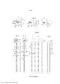
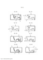
[0080] As Figuras 1a a e ilustram um sistema de travamento de flexão para baixo de acordo com princípios conhecidos.[0080] Figures 1a to e illustrate a downward bending locking system according to known principles.
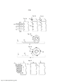
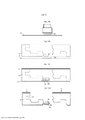
[0081] As Figuras 2a a f ilustram modalidades dos métodos de produção que podem ser usados para formar sulcos e cavidades.[0081] Figures 2a to f illustrate embodiments of production methods that can be used to form grooves and cavities.
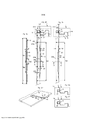
[0082] As Figuras 3a a f ilustram a flexão de uma lingueta flexível de acordo com uma modalidade.[0082] Figures 3a to f illustrate the bending of a flexible tongue according to one embodiment.
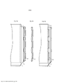
[0083] As Figuras 4a a f ilustram a formação de uma lingueta flexível de um modelo de lingueta extrudado ou um material de folha de acordo com uma modalidade da invenção.[0083] Figures 4a to f illustrate the formation of a flexible tongue of an extruded tongue pattern or sheet material in accordance with an embodiment of the invention.
[0084] As Figuras 5a a f ilustram um sistema de travamento que compreende cavidades e protuberâncias providas nos painéis de acordo com uma modalidade.[0084] Figures 5a to f illustrate a locking system comprising cavities and protrusions provided in the panels according to one embodiment.
[0085] As Figuras 6a a f ilustram o deslocamento e a flexão de uma lingueta separada em formato de haste de acordo com uma modalidade.[0085] Figures 6a to f illustrate displacement and bending of a separate rod-shaped tongue according to one embodiment.
[0086] As Figuras 7a a b ilustram um método para separar e inserir uma lingueta flexível em um sulco de acordo com uma modalidade.[0086] Figures 7a to b illustrate a method for separating and inserting a flexible tongue into a groove according to one embodiment.
[0087] As Figuras 8a a c ilustram a formação e a inserção de uma lingueta flexível que compreende protuberâncias de acordo com uma modalidade.[0087] Figures 8a to c illustrate the formation and insertion of a flexible tongue comprising protuberances according to one embodiment.
[0088] As Figuras 9a a-d ilustram métodos alternativos para introduzir e flexionar uma lingueta flexível de acordo com várias modalidades.[0088] Figures 9a to d illustrate alternative methods for introducing and flexing a flexible tongue according to various embodiments.
[0089] As Figuras 10a a c ilustram a formação de uma lingueta flexível de acordo com uma modalidade.[0089] Figures 10a to c illustrate the formation of a flexible tongue according to one embodiment.
[0090] As Figuras 11a a b ilustram a formação de uma lingueta flexível que compreende partes superior e inferior deslocadas de acordo com uma modalidade.[0090] Figures 11a to b illustrate the formation of a flexible tongue comprising displaced upper and lower parts according to one embodiment.
[0091] As Figuras 12a a e ilustram a formação de uma lingueta flexível que compreende partes superior e inferior deslocadas de acordo com várias modalidades.[0091] Figures 12a to e illustrate the formation of a flexible tongue comprising displaced upper and lower parts according to various embodiments.
[0092] As Figuras 13a a h ilustram várias modalidades de acordo com um aspecto da invenção.[0092] Figures 13a to h illustrate various embodiments in accordance with an aspect of the invention.
[0093] As Figuras 14a a d ilustram um método para reforçar uma lingueta flexível de acordo com uma modalidade.[0093] Figures 14a to d illustrate a method for reinforcing a flexible tongue according to one embodiment.
[0094] As Figuras 15a a b ilustram sistemas de travamento e componentes de mobília e lajotas de cerâmica de acordo com duas modalidades.[0094] Figures 15a to b illustrate locking systems and furniture components and ceramic tiles according to two modalities.
[0095] As Figuras 16a a c ilustram a formação de uma lingueta flexível curva de acordo com uma modalidade.[0095] Figures 16a to c illustrate the formation of a curved flexible tongue according to one embodiment.
[0096] As Figuras 1a a 1e ilustram as linguetas flexíveis e o travamento de uma primeira borda 1 e uma segunda borda 1' do painel com deslocamento vertical de acordo com princípios conhecidos. Uma lingueta de cerda flexível 10 que compreende um do corpo de lingueta 20 e as protuberâncias flexíveis 21 em sua parte interna tal como mostrado na Figura 1b, ou em sua parte externa tal como mostrado na Figura 1c, é deslocada para dentro rumo a um sulco de deslocamento 11 durante o travamento tal como mostrado na Figura 1a e para fora durante o estágio final do travamento de maneira tal que as partes externas da lingueta flexível 10 são inseridas em um sulco de lingueta 9 e as bordas adjacentes do primeiro painel 1 e do segundo painel 1' são travadas verticalmente paralelas a um plano vertical VP. As bordas de painel compreendem uma tira 6 com um elemento de travamento 8 em uma das bordas que coopera com um sulco de travamento 14 formado na borda adjacente e trava as bordas em uma direção horizontal paralela à superfície do painel e perpendicular ao plano vertical.[0096] Figures 1a to 1e illustrate the flexible tongues and the locking of a
[0097] A Figura 1b mostra uma lingueta de cerda 10 com um corpo de lingueta 20 e as protuberâncias flexíveis 21 em sua parte interna. A Figura 1c mostra uma lingueta de cerda 10 com um corpo de lingueta 20 e as protuberâncias flexíveis 21 em sua parte externa.[0097] Figure 1b shows a
[0098] A lingueta flexível tem uma direção do comprimento L ao longo da borda, uma largura W que se estende horizontalmente perpendicular à borda, e uma espessura de lingueta TT na direção vertical. A espessura de lingueta TT é geralmente a mesma que a espessura de sulco GT do sulco de deslocamento 11. A largura máxima W é maior do que a profundidade de sulco GD do sulco de deslocamento 11.[0098] The flexible tongue has a length direction L along the edge, a width W that extends horizontally perpendicular to the edge, and a tongue thickness TT in the vertical direction. The tongue thickness TT is generally the same as the groove thickness GT of the offset
[0099] A lingueta flexível compreende uma geometria complexa e é formada consequentemente como um componente à base de termoplástico moldado injetado que compreende fibras de vidro que são usadas para prover uma alta resistência combinada com a flexibilidade. Uma flexão das protuberâncias na direção do comprimento da lingueta é uma característica essencial de tais linguetas flexíveis avançadas.[0099] The flexible tongue comprises a complex geometry and is consequently formed as an injected molded thermoplastic based component comprising glass fibers that are used to provide high strength combined with flexibility. A bending of the protuberances in the direction of the length of the tongue is an essential feature of such advanced flexible tongues.
[00100] As Figuras 1d e 1e mostram que a lingueta flexível 10 é produzida e entregue como um modelo de lingueta 30 que compreende, por exemplo, de 8 a 32 linguetas. O material de plástico é injetado em uma ferramenta através dos canais de injeção 31, em geral de um lado apenas a fim de reduzir os custos de produção. O material do canal é removido após a formação com injeção e pode ser refundido e usado novamente.[00100] Figures 1d and 1e show that the
[00101] A moldagem a injeção com o material termoplástico que compreende as fibras de vidro é um método econômico que provê componentes de alta qualidade com as tolerâncias de produção muito baixas. No entanto, o método de produção e a geometria da lingueta flexível têm várias desvantagens que limitam as possibilidades para a produção de sistemas de travamento econômicos que compreendem linguetas flexíveis em um novo tipo de painéis de piso e materiais de núcleo onde uma instalação com flexão para baixo é desejável.[00101] Injection molding with thermoplastic material comprising glass fibers is an economical method that provides high quality components with very low production tolerances. However, the production method and the geometry of the flexible tongue have several disadvantages that limit the possibilities for the production of cost-effective locking systems comprising flexible tongues in a new type of floor panels and core materials where an installation with bending to low is desirable.
[00102] Uma desvantagem é que uma lingueta flexível deve ter um comprimento L que corresponda à largura do painel uma vez que é inserida em um sulco formado na borda curta.[00102] A disadvantage is that a flexible tongue must have a length L that matches the width of the panel as it is inserted into a groove formed on the short edge.
[00103] O material de plástico deve fluir através de um corpo 20 da lingueta ao longo do comprimento L da lingueta 10 e deve haver um espaço S entre as protuberâncias 21 e o corpo 20 da lingueta, vide as Figuras 1d e 1e. Isso provê determinados limites relacionados ao custo para a geometria da lingueta. Por exemplo, o tempo de produção e o custo da ferramenta podem aumentar de maneira considerável se a largura W for menor do que 4 mm, a espessura TT for menor do que 1,5 mm e o comprimento for maior do que cerca de 300 mm.[00103] The plastic material must flow through a
[00104] Um outro problema é que é difícil formar um sulco de deslocamento com uma espessura GT do sulco que seja menor do que cerca de 1,5 mm se a profundidade GD do sulco for cerca de 4 mm.[00104] Another problem is that it is difficult to form a displacement groove with a groove thickness GT that is less than about 1.5 mm if the groove depth GD is about 4 mm.
[00105] Os sistemas de travamento mecânicos são formados de modo geral com grandes ferramentas de rotação que formam sulcos e partes salientes paralelas a uma borda e ao longo de toda a borda.[00105] Mechanical locking systems are generally formed with large rotating tools that form grooves and protruding parts parallel to an edge and along the entire edge.
[00106] As Figuras 2a a 2e mostram modalidades de métodos de produção que podem ser usados para a formação de sistemas de travamento e linguetas que compreendem as cavidades 22 e as protuberâncias 21 arranjadas perpendiculares a uma borda 1 de acordo com um aspecto da invenção.[00106] Figures 2a to 2e show embodiments of production methods that can be used for forming locking systems and
[00107] A figura 2a é uma vista superior que mostra uma ferramenta que compreende as lâminas de serra rotativa 40 que são deslocadas de encontro a uma borda do painel 1 e de volta novamente. Alternativamente, o painel 1 pode ser deslocado de encontro às lâminas de serra 40 e de volta novamente. Esse método de produção pode ser usado para formar as cavidades 22 ou as protuberâncias 21 tal como mostrado nas Figuras a 2b e a 2c, em que as figuras superiores ilustram vistas em perspectiva e as figuras inferiores ilustram vistas superiores da borda do painel 1.[00107] Figure 2a is a top view showing a tool comprising rotary saw blades 40 that are displaced against an edge of
[00108] A Figura 2d mostra uma vista lateral de uma chamada cabeça de ferramenta de oscilar rotativa 41 que pode ser deslocada vertical ou horizontalmente de encontro a uma borda móvel do painel 1. Desse modo, as cavidades locais 22 podem ser formadas.[00108] Figure 2d shows a side view of a so-called rotating
[00109] A Figura 2e mostra um método econômico para a formação das cavidades 22 com uma ferramenta de entalhar rota rotativa 45. A ferramenta de entalhar 45 compreende os dentes 46 que são arranjados ao longo de uma borda externa da ferramenta de entalhar 45. A velocidade de rotação da ferramenta é sincronizada com o deslocamento do painel 1 e cada dente 46 forma uma cavidade 22 em uma posição predeterminada e com uma extensão horizontal predeterminada ao longo de uma borda de um painel 1. Não é necessário deslocar verticalmente a ferramenta. Uma ferramenta de entalhar 45 pode ter vários conjuntos de dentes 46 e cada conjunto pode ser usado para formar uma cavidade. As cavidades 22 podem ter seções transversais diferentes dependendo da geometria dos dentes 46.[00109] Figure 2e shows an economical method for forming the
[00110] A Figura 2f mostra uma vista superior de um chamado cortador de parafuso 42. Esta é uma tecnologia de produção avançada que permite uma alta precisão e a formação econômica de protuberâncias e cavidades perpendiculares a uma borda que é deslocada a alta velocidade de encontro ao cortador de parafuso 42. O documento de patente WO 2010/087752 provê uma descrição detalhada do princípio do cortador de parafuso.[00110] Figure 2f shows a top view of a so-called 42 screw cutter. This is an advanced production technology that allows high precision and economical formation of bulges and cavities perpendicular to an edge that is displaced at high speed against to the
[00111] A Figura 3a mostra uma lingueta flexível 10 de acordo com uma modalidade. Uma largura W da lingueta flexível 10 é essencialmente a mesma em substancialmente todo o comprimento L da lingueta flexível 10.[00111] Figure 3a shows a
[00112] As Figuras 3b e 3c mostram uma imagem ampliada de uma parte Ts1 da lingueta mostrada na Figura 3a e uma seção transversal A-A da lingueta flexível 10 inserida em um sulco de deslocamento 11 provido borda do painel 1.[00112] Figures 3b and 3c show an enlarged image of a part Ts1 of the tongue shown in Figure 3a and a cross-section A-A of the
[00113] A Figura 3b mostra a lingueta flexível 10 em uma posição destravada e uma posição travada. A posição destravada é ilustrada pela borda superior do painel 1' que é indicada por uma linha contínua, ao passo que a posição travada é ilustrada pela borda inferior do painel 1' que é indicada por uma linha descontínua. A lingueta flexível 10 é inserida em um sulco de deslocamento 11 que compreende uma virola superior 12. Um plano vertical VP intercepta a parte superior e externa da virola superior 12. A lingueta compreende pelo menos duas seções da lingueta Ts1, Ts2, cada uma das quais compreende uma superfície de deslizamento 15 que, durante o travamento, coopera com uma borda deslizante 17 da borda adjacente 1', e uma superfície de travamento 16 que trava no sulco 9 da lingueta. De acordo com a presente modalidade, a superfície de deslizamento 15 é provida em uma parte superior da lingueta flexível 10. Mais especificamente, a superfície de deslizamento 15 é uma parte inclinada externa e superior da lingueta flexível 10. Além disso, de acordo com a presente modalidade, a superfície de travamento 16 é provida em uma parte mais inferior da lingueta flexível 10. Mais especificamente, a superfície de travamento 16 é uma parte inclinada externa e inferior da lingueta flexível 10. A superfície de deslizamento 15 é arranjada acima da superfície de travamento 16. As seções da lingueta Ts1, Ts2 são espaçadas entre si na direção do comprimento L da lingueta flexível 10. A lingueta é curva em uma posição travada e uma posição destravada de maneira tal que uma primeira distância horizontal D1 do plano vertical VP e à parte externa da lingueta flexível 10 e uma segunda distância horizontal D2 do plano vertical VP a uma parte interna da lingueta flexível 10 variam ao longo do comprimento L da lingueta.[00113] Figure 3b shows the
[00114] O formato da lingueta flexível 10 também pode ser definido por uma terceira distância horizontal D3 da parte interna da lingueta a uma linha horizontal interna que conecta os pontos mais internos da lingueta. A linha interna é essencialmente paralela com uma direção do comprimento da lingueta flexível 10. A linha interna é uma linha reta se cada uma das seções da lingueta secionar Ts1, Ts2... tiver o mesmo formato. Em um primeiro exemplo, D1 corresponde a D3 ao longo de toda a direção do comprimento da lingueta flexível 10, provendo desse modo uma largura constante W da lingueta flexível 10. Em um segundo exemplo, D1 difere de D3 pelo menos ao longo de uma parte da direção do comprimento da lingueta flexível 10, provendo desse modo uma largura variável W.[00114] The shape of the
[00115] É evidente que as modalidades ilustradas do presente pedido de patente não são limitadoras no que diz respeito ao número de seções da lingueta. Certamente, pode haver um ou mais seção da lingueta Ts1, Ts2., TsN, onde N é um número inteiro arbitrário maior do que ou igual a um, isto é N = 1, 2, 3, 4.[00115] It is evident that the illustrated embodiments of the present patent application are not limiting with regard to the number of sections of the tongue. Of course, there may be one or more tongue sections Ts1, Ts2., TsN, where N is an arbitrary integer greater than or equal to one, i.e. N = 1, 2, 3, 4.
[00116] A Figura 3c mostra a lingueta flexível 10 em uma posição interna durante o travamento. De acordo com a presente modalidade, a borda adjacente 1' é deslocada essencialmente verticalmente para baixo para a primeira borda do painel 1 durante o travamento, de maneira tal que o sulco de travamento 14 provido na borda adjacente 1' é abaixado para e coopera com o elemento de travamento 8 provido na primeira borda do painel 1. A lingueta flexível 10 é pressionada para dentro pela borda deslizante 17 do painel adjacente 1' e as seções curvas Ts1, Ts2 são endireitadas de maneira tal que a lingueta flexível 10 é formada como um componente em formato de haste essencialmente retilínea com uma largura W da lingueta que é essencialmente a mesma ao longo da parte maior da lingueta flexível. Em uma modalidade, durante o travamento de uma seção da lingueta, a distância D3 pode mudar de uma distância destravada para menos de 20% da distância destravada. Deve ser observado que a superfície de deslizamento 15, que se projeta para fora além do plano vertical VP em uma posição travada bem como em uma posição destravada, tal como ilustrado na Figura 3b, é pressionada na direção do sulco de deslocamento 11 durante o travamento tal como ilustrado na Figura 3c. Desse modo, a superfície de deslizamento 15 pode ser pressionada para dentro do plano vertical VP durante o travamento - parcial ou completamente.[00116] Figure 3c shows the
[00117] Tal como mostrado na Figura 3b, a lingueta flexível 10 compreende as protuberâncias internas 21a 3b e as protuberâncias externas 21b arranjadas ao longo de um direção do comprimento da lingueta em uma parte interna e uma parte externa da lingueta, respectivamente. Na Figura 3b pode ser visto que a seção Ts1 da lingueta que compreende uma protuberância externa 21b foi endireitada como uma seção essencialmente reta.[00117] As shown in Figure 3b, the
[00118] A Figura 3d mostra uma modalidade de acordo com a qual os painéis compreendem as bordas curtas 1, 1' e as bordas longas 4. Um movimento de tesoura da borda curta adjacente 1' causado pela flexão da borda longa 4 do painel irá pressionar gradualmente as seções da lingueta interna ao longo da borda do painel e deformar a lingueta flexível 10 como um componente essencialmente reto. Por exemplo, pelo menos uma seção de lingueta da lingueta flexível 10, que tem uma borda externa convexa ou côncava ao longo da direção do comprimento da seção da lingueta, pode ser endireitada de modo que um ponto externo da borda da borda externa convexa ou côncava se move para o sulco de deslocamento 11, em que o ponto externo da borda é um ponto na seção da lingueta mais distanciado do sulco de deslocamento 11. Na Figura 3b o ponto externo da borda fica localizado em uma parte central da seção convexa Ts1 da lingueta ao longo de sua direção do comprimento onde uma distância XM até a parede interna do sulco de deslocamento 11 é máxima. Deve ser observado que, em uma seção côncava Ts0 da lingueta, tal como mostrado na Figura 3b, o ponto externo da borda pode ficar localizado em uma parte da borda da seção côncava da lingueta ao longo de sua direção do comprimento onde uma distância até a parede interna do sulco de deslocamento 11 é máxima. A título de exemplo, o ponto externo da borda pode se mover para o sulco de deslocamento 11 por pelo menos uma distância que corresponde a 20 a 60% de uma largura máxima da lingueta 10, de preferência de 40 a 50%. Em particular, a lingueta flexível 10 pode ser endireitada como um componente essencialmente reto, por exemplo, um componente reto ao longo de todo o seu comprimento. De preferência, as partes externas da lingueta flexível 10 e o sulco 9 da lingueta são configurados de maneira tal que uma parte interna da borda 1a e uma primeira parte Ts1 da lingueta ficam perto de sua posição travada final, tal como mostrado na Figura 3e, quando uma parte externa da borda 1b e uma segunda parte Ts2 da lingueta, de preferência uma parte da lingueta que fica mais distante da primeira parte Ts1 da lingueta, fica em sua posição interna tal como mostrado na Figura 3f. As seções da borda Ts1, Ts2 irão se mover gradualmente para o sulco 9 da lingueta durante a flexão vertical e a resistência ao travamento e as forças de separação, que podem pressionar as bordas curtas parta afastar uma da outra devido à flexão da lingueta, serão reduzidas. Isso facilita um travamento fácil.[00118] Figure 3d shows an embodiment according to which the panels comprise the
[00119] A lingueta flexível 10 pode compreender as conexões de fricção 23, localizadas de preferência em uma parte superior e/ou inferior da lingueta. As conexões de fricção 23 podem ser alongadas. A flexibilidade requerida é obtida principalmente por um corpo flexionado da lingueta 20 da lingueta que flexiona durante o travamento principalmente horizontalmente e para dentro para o sulco de deslocamento 11.[00119] The
[00120] A lingueta flexível 10 pode compreender partes da lingueta com seções transversais em que a primeira distância horizontal D1 é essencialmente a mesma que a segunda distância horizontal D2 de maneira tal que a largura W da lingueta pode ser cerca de 2 vezes a largura da superfície de deslizamento 15 que se projeta além do plano vertical VP. A lingueta flexível 10 pode ser formada com uma seção transversal muito compacta de maneira tal que a largura W da lingueta é essencialmente a mesma que a espessura TT da lingueta.[00120] The
[00121] A modalidade descrita oferece várias vantagens. A posição interna reta torna possível a formação de sulcos de deslocamento com uma profundidade muito pequena. A geometria simples da lingueta permite uma produção econômica, uma vez que o material de plástico pode flutuar facilmente durante a moldagem a injeção e isso torna possível diminuir a largura W da lingueta e a espessura TT da lingueta e aumentar o comprimento L da lingueta. É possível produzir uma lingueta moldada a injeção com uma espessura TT que seja menor do que 1,5 mm, por exemplo, com uma espessura de cerca de 1,0 a 1,5 mm e com uma largura W de cerca de 1,5 a 3 mm. Também é possível produzir linguetas flexíveis extremamente finas com uma espessura TT da lingueta de 0,5 a 1,0 mm. Tais linguetas podem ser usadas para travar painéis de piso muito finos, por exemplo, painéis de piso de LVT ou de WPC com uma espessura de cerca de 3 mm.[00121] The described modality offers several advantages. The straight internal position makes it possible to form displacement grooves with a very small depth. The simple tongue geometry allows economical production as the plastic material can float easily during injection molding and this makes it possible to decrease the tongue width W and tongue thickness TT and increase the tongue length L. It is possible to produce an injection molded tongue with a thickness TT that is less than 1.5 mm, for example with a thickness of about 1.0 to 1.5 mm and a width W of about 1.5 mm. to 3 mm. It is also possible to produce extremely thin flexible tongues with a tongue thickness TT of 0.5 to 1.0 mm. Such tongues can be used to lock very thin floor panels, for example LVT or WPC floor panels with a thickness of about 3 mm.
[00122] Uma rigidez da lingueta flexível pode ser especificada por uma constante de mola transversal. De acordo com um exemplo não limitador, a constante de mola transversal da mola da lingueta flexível fica entre 5 e 50 N/mm por 100 mm de comprimento da lingueta. De acordo com um outro exemplo não limitador, a constante de mola transversal fica entre 15 e 25 N/mm por 100 mm de comprimento da lingueta. A constante de mola transversal da lingueta flexível pode ser testada pelos métodos padrão conhecidos de alguém versado na técnica.[00122] A stiffness of the flexible tongue can be specified by a transverse spring constant. According to a non-limiting example, the transverse spring constant of the spring of the flexible pawl is between 5 and 50 N/mm per 100 mm pawl length. According to another non-limiting example, the transverse spring constant is between 15 and 25 N/mm per 100 mm pawl length. The transverse spring constant of the flexible tongue can be tested by standard methods known to one skilled in the art.
[00123] A Figura 4a ilustra uma vista superior e uma vista em seção transversal de um modelo de lingueta 30 de acordo com uma modalidade. As Figuras 4a e 4b mostram que a lingueta flexível 10 pode ser formada a partir de um modelo de lingueta 30 que é um componente de plástico ou metal extrudado que compreende uma seção transversal idêntica ao longo de todo o comprimento do modelo de lingueta. Em particular, o modelo de lingueta 30 tem uma largura constante ao longo de sua direção do comprimento. Uma roda perfurante 43 pode formar partes curvas da lingueta flexível 10. As partes curvas são formadas ao remover o material do modelo de lingueta 30. De acordo com a presente modalidade, o material é removido de uma parte interna e de uma parte externa do modelo de lingueta 30 de uma maneira tal que uma largura da lingueta flexível 10 resultante fica essencialmente constante ao longo de uma direção do comprimento da lingueta flexível 10. A lingueta flexível 10 pode ter as conexões de fricção 2 projetadas verticalmente para cima ou para baixo. Isso é ilustrado na vista superior da lingueta flexível 10 de acordo com a modalidade na Figura 4b.[00123] Figure 4a illustrates a top view and a cross-sectional view of a
[00124] De acordo com uma modalidade alternativa, o material pode ser removido de uma parte interna e/ou de uma parte externa do modelo de lingueta 30 de uma maneira tal que a largura da lingueta flexível 10 resultante fica não constante ao longo da direção do comprimento da lingueta flexível 10. Os exemplos das linguetas flexíveis 10 que têm larguras não constantes serão descritos mais adiante com relação às modalidades nas Figuras 9b, 9c e 12c.[00124] According to an alternative embodiment, material can be removed from an inner and/or an outer part of the
[00125] De acordo com modalidades alternativas, as partes curvas da lingueta flexível 10 podem ser formadas por outros meios, tais como corte, entalhe, perfuração ou fresagem, ou qualquer combinação desses meios.[00125] According to alternative embodiments, the curved parts of the
[00126] O modelo de lingueta 30 e/ou a lingueta flexível 10 podem ser formados por meio de moldagem a injeção, extrusão, impressão 3D mediante a formação de camadas sucessivas, ou pultrusão com um material de reforço.[00126] The
[00127] De modo geral, o modelo de lingueta 30 e/ou a lingueta flexível 10 podem compreender pelo menos um material escolhido do grupo que consiste em um plástico, tal como um plástico termoplástico ou termorrígido, um WPC, um metal, ou um material de painel, tal como um material de núcleo de painel ou um material de pelo menos uma camada de um painel. O material também pode compreender um material de reforço. Desse modo, o material pode se tornar mais rígido. Por exemplo, o material de reforço pode compreender fibras ou resinas, tais como resinas termorrígidas. Alternativa ou adicionalmente, o material pode compreender um material reticulado, tal como um plástico com polímeros reticulados.[00127] In general, the
[00128] O termoplástico pode compreender PVC, PE, PP, CPVC, ou materiais similares. Em exemplos não limitadores, o polietileno pode ser um PE de baixa densidade, um PE linear de baixa densidade, um PE de média densidade ou um PE de alta densidade. Em particular, o termoplástico pode ser um termoplástico reticulado, tal como o polietileno reticulado, também chamado de PEX ou XLPE. Além disso, o termoplástico pode ser um termoplástico reforçado. O termoplástico reforçado pode compreender um material de reforço, tais como fibras. As fibras podem compreender pelo menos um dentre fibras de vidro, fibras de carbono, fibras de aramida, fibras de madeira, fibras de basalto, fibras não trançadas, ou fibras têxteis. Alternativamente, as fibras podem compreender fibras de metal, tais como fibras de metais magnéticos, por exemplo, ferro ou uma liga magnética. Desse modo, as fibras podem ser separadas do plástico mais facilmente durante a reciclagem. As fibras podem ter uma orientação específica. Por exemplo, as fibras podem ser orientadas ao longo de uma direção do comprimento da lingueta flexível 10. Alternativamente, as fibras podem ser orientadas de maneira aleatória. As fibras podem ser distribuídas de maneira aleatória na lingueta flexível 10. Alternativamente, as fibras podem ser arranjadas na forma de uma camada em forma de esteira na lingueta flexível 10, tal como um tecido, por exemplo, em uma parte central da lingueta flexível 10.[00128] The thermoplastic may comprise PVC, PE, PP, CPVC, or similar materials. In non-limiting examples, the polyethylene can be a low density PE, a linear low density PE, a medium density PE or a high density PE. In particular, the thermoplastic may be a cross-linked thermoplastic, such as cross-linked polyethylene, also called PEX or XLPE. In addition, the thermoplastic can be a reinforced thermoplastic. The reinforced thermoplastic may comprise a reinforcing material, such as fibers. The fibers may comprise at least one of glass fibers, carbon fibers, aramid fibers, wood fibers, basalt fibers, non-woven fibers, or textile fibers. Alternatively, the fibers may comprise metal fibers, such as fibers of magnetic metals, for example iron or a magnetic alloy. In this way, the fibers can be separated from the plastic more easily during recycling. The fibers can have a specific orientation. For example, the fibers may be oriented along a direction along the length of the
[00129] Desse modo, a lingueta flexível 10 compreende de preferência um material de baixa fluência que não escoe nem deforme até nenhuma extensão considerável com o passar do tempo. Desse modo, a função de travamento não se deteriora com o passar do tempo, por exemplo, depois de 1 mês, 1 ano, ou 10 anos. Ambos os materiais reforçados e reticulados descritos acima podem neutralizar a fluência. As Figuras 4d a 4f mostram que os modelos de lingueta 30 das linguetas podem ser formados a partir de um material em forma de folha 50. O material em forma de folha 50, que é ilustrado na Figura 4d no caso de uma folha de uma só camada, pode ser um material termoplástico, de preferência compreendendo cargas minerais ou de madeira. De preferência, pelo menos três camadas são laminadas ou fundidas umas às outras. Fibras de vidro ou quaisquer outras fibras descritas acima podem ser usadas para reforçar o material em forma de folha. O material em forma de folha também pode compreender resinas termorrígidas misturadas de preferência com fibras de madeira. A Figura 4f mostra um material em forma de folha 50 que compreende pelo menos três camadas. As camadas superior 51a e inferior 51c compreendem um material termoplástico e a camada do meio 51b é uma camada de reforço que compreende fibras, por exemplo, fibras de vidro. A camada do meio 51b é uma camada em forma de esteira que compreende fibras. No entanto, é evidente que outros materiais descritos acima podem ser usados para as camadas 51a-c. Por exemplo, as camadas superior 51a e inferior 51c podem compreender um plástico termorrígido e/ou a camada do meio 51b pode compreender fibras distribuídas de maneira aleatória. De acordo com a modalidade na Figura 4e, a lingueta flexível 10 compreende pelo menos três camadas de materiais com propriedades de materiais diferentes. As camadas e as camadas de reforço podem ser unidas por meio de aquecimento e/ou compressão. Os rolos em relevo quentes podem ser usados para formar os sulcos retos 52a ou flexionados 52b no material em forma de folha 50 que, após a separação, formam as partes externas e/ou internas de uma lingueta flexível 10. Os sulcos também podem ser formados com ferramentas de cortar ou entalhar rotativas. Uma ferramenta de perfuração 43, ou roda de perfuração 43, também pode ser usada para formar as linguetas flexíveis 10. Todos esses métodos de produção podem ser combinados. As linguetas flexíveis 10 também podem ser formadas com métodos de impressão 3D. Com relação às Figuras 4d-f, três camadas foram escolhidas para finalidades ilustrativas somente e é evidente que qualquer número de camadas pode ser escolhido, por exemplo, 1, 2, 3, 4, 5, 6 ou 7 camadas. Além disso, pode haver uma pluralidade de camadas de reforço. Por exemplo, pode haver uma camada central imprensada entre as superfícies internas de uma primeira e uma segunda camadas de reforço, e uma camada superior e uma camada inferior arranjadas nas superfícies externas das primeira e segunda camadas de reforço, respectivamente.[00129] Thus, the
[00130] A Figura 5a mostra que a lingueta flexível 10 pode ser formada como um componente no formato de haste reta. A Figura 5b mostra que as cavidades 22a, 22b podem ser formadas na parte interna do sulco de deslocamento 11 de um primeiro painel 1 e que as protuberâncias 21 podem ser formadas no segundo painel adjacente 1'. As cavidades 22a, 22b e as protuberâncias 21 são formadas ao longo das partes das bordas laterais dos painéis 1, 1' em sua direção do comprimento. Cada cavidade compreende uma parede de cavidade superior 26, interna 27 e inferior 28 contínua e uma abertura de cavidade horizontal 29 para o plano vertical VP. As paredes da cavidade são de preferência contínuas ao longo da borda, uma vez que elas sejam de preferência formadas com uma ferramenta de entalhar ou oscilar rotativa. Pelo menos uma parte da parede da cavidade interna 27 é curva. Cada protuberância 21 compreende uma parede horizontal superior e uma parede externa. De acordo com a presente modalidade, a parede externa é inclinada. De acordo com uma modalidade alternativa, no entanto, a parede externa pode ser vertical e a protuberância também pode compreender uma parede horizontal inferior que seja essencialmente paralela com a parede superior. As cavidades 22a, 22b podem ter a mesma extensão vertical que o sulco de deslocamento 11. Alternativamente, as cavidades 22a, 22b podem ter uma extensão vertical maior do que o sulco de deslocamento 11. Isso provê uma produção mais econômica, uma vez que ferramentas de oscilar ou lâminas de serra saltando maiores e mais eficientes podem ser usadas e as tolerâncias da produção podem ser aumentadas sem efeitos negativos na função de travamento. De acordo com uma modalidade alternativa, as cavidades 22a, 22b podem ter uma extensão vertical menor do que o sulco de deslocamento 11.[00130] Figure 5a shows that the
[00131] As Figura 5c a 5f mostram que as protuberâncias 21 e as cavidades 22 são localizadas ao longo das bordas do painel e adjacentes entre si de maneira tal que uma protuberância 21 pode deslocar e flexionar uma parte de uma seção Ts1 da lingueta para a cavidade 22. A Figura 5d mostra uma seção transversal A-A que compreende uma cavidade 22a que tem uma extensão vertical ou espessura de cavidade Ct mais ou menos idêntica à espessura GT do sulco de deslocamento 11. A Figura 5e mostra uma modalidade alternativa da seção transversal A-A em que uma cavidade 22b tem uma espessura maior da cavidade do que o sulco de deslocamento 11 e é deslocada verticalmente abaixo das partes superior ou inferior do sulco de deslocamento. A lingueta deslocável 10 pode ter uma parte externa com uma espessura externa TTa da lingueta maior do que uma espessura TTb da lingueta de uma parte interna. Uma vantagem é que a parte interna da lingueta pode ser deslocada para uma cavidade mesmo se a posição vertical da ferramenta de formação não estiver alinhada com a parte superior do sulco de deslocamento 11. De acordo com uma modalidade alternativa, a cavidade 22b pode ter uma espessura da cavidade menor do que o sulco de deslocamento 11. A Figura 5f mostra uma seção transversal B-B em que nenhuma cavidade e protuberância é formada e onde não ocorre essencialmente nenhum deslocamento da lingueta flexível 10 no sulco de deslocamento 11. Essa parte da borda é usada como um suporte para a flexão interna da seção Ts1 da lingueta.[00131] Figures 5c to 5f show that the
[00132] As Figuras 6a a 6i mostram em detalhes o deslocamento de uma lingueta em forma de haste flexível 10 de acordo com as Figuras 5a a 5f. A Figura 5a mostra uma vista superior de uma primeira 1 e uma segunda 1' seção da borda nos planos horizontais HP 1 e HP 1' de acordo com as Figuras 6b e 6c. Aqui, a lingueta é essencialmente reta. As Figuras 6d-f mostram a lingueta flexível 10 em uma posição interna flexionada na qual as partes da lingueta flexível 10 foram pressionadas nas cavidades 22 por meio das protuberâncias 21. As Figuras 6g a 6i mostram a lingueta flexível 10 em uma posição externa e travada na qual o sulco 9 da lingueta e o sulco de deslocamento 11 são alinhados verticalmente de modo que as partes externas da lingueta flexível 10 são inseridas no sulco 9 da lingueta. De acordo com a presente modalidade, a lingueta flexível 10 é essencialmente reta na posição externa e travada. De acordo com uma modalidade alternativa (não mostrada), no entanto, pelo menos uma parte da lingueta flexível 10 pode ser flexionada na posição externa e travada. Por exemplo, a lingueta flexível 10 pode ser flexionada nas seções.[00132] Figures 6a to 6i show in detail the displacement of a flexible rod-shaped
[00133] As Figuras 7a e 7b mostram um método para a formação de uma lingueta, de preferência uma lingueta flexível 10, a partir de uma parte da borda de um painel 1 e para a inserção da lingueta em um sulco, de preferência um sulco de deslocamento 11, de preferência na mesma linha de produção que é usada para formar o sistema de travamento. A lingueta flexível 10 é nesta modalidade formada em uma parte externa da tira 6. As rodas de compressão 44a, 44b e 44c podem ser usadas para separar a lingueta 10 da borda 1 e deslocar a lingueta vertical e horizontalmente para o sulco 11. É preferível que uma parte P1 da lingueta seja conectada à borda 1 quando uma outra parte P2 é inserida e fixada no sulco 11. A lingueta 10 também pode ser liberada da borda 1 e ser deslocada com as rodas 44a, 44b, de preferência à mesma velocidade que a borda do painel 1, e ser inserida no sulco de deslocamento 11 com as rodas 44c ou algumas unidades de compressão. Unidades de suporte superior e inferior podem ser usadas para alinhar e posicionar a lingueta no sulco. A lingueta pode ser usada em um sistema de travamento tal como descrito nas Figuras 5a a 5f.[00133] Figures 7a and 7b show a method for forming a tongue, preferably a
[00134] Tal método de produção oferece várias vantagens. Os modelos de lingueta não são necessários e a lingueta 10 terá sempre um comprimento apropriado que corresponda à borda do painel. Uma ampla variedade de materiais do núcleo foi apresentada no mercado, tais como HDF, HDF de alta densidade resistente à água que compreende um maior teor de resina, material termoplástico misturado com carga minerais ou de fibra de madeira, o chamado material de LVT ou de WPC, material termoplástico em espuma, etc. Qualquer um dos materiais acima mencionados pode ser usado para formar a lingueta flexível 10 de acordo com a modalidade nas Figuras 7a-b. Os materiais de piso termoplásticos são reforçados frequentemente com fibras de vidro a fim de diminuir a contração e a expansão térmicas. As fibras de vidro 47 podem ser localizadas na parte do núcleo 6 onde a lingueta flexível 10 é formada e podem contribuir para aumentar as propriedades de resistência e de elasticidade da lingueta flexível 10. Tais materiais têm uma flexibilidade suficiente e podem prover um corpo forte e flexível da lingueta. Os pisos de madeira projetados têm em geral um material separado tal como a madeira compensada no lado curto, e esse material separado também pode ser usado para formar a lingueta flexível. Os materiais de piso termoplástico são reforçados frequentemente com fibras de vidro a fim de diminuir a contração e a expansão térmicas. Tais camadas de fibra de vidro são posicionadas nas partes do meio do núcleo 6. As fibras de vidro 47 podem ser posicionadas na parte do núcleo 6, de preferência na parte inferior, onde a lingueta flexível 10 é formada e podem contribuir para aumentar as propriedades de resistência e de elasticidade da lingueta flexível 10.[00134] Such a production method offers several advantages. Tongue templates are not required and the
[00135] As Figuras 8a a 8c - mostram que linguetas curvas bastante complexas 10 podem ser formadas com cortadores de parafusos, cabeças de ferramentas de oscilar ou rodas de perfuração e que as cavidades e as protuberâncias formadas nas bordas do painel não são necessárias para deslocar uma lingueta flexível 10 em um sulco de deslocamento 11. A Figura 8a mostra uma lingueta 10 formada e conectada a uma parte externa de uma tira 6. A Figura 8b mostra a lingueta flexível 10 que é liberado da tira 6 e a Figura 8c mostra a lingueta deslocável 10 inserida em um sulco de deslocamento 11.[00135] Figures 8a to 8c - show that quite complex
[00136] Por uma lingueta curva entende-se que pelo menos uma seção da lingueta é curva. A lingueta curva pode compreender qualquer número de seções curvas, por exemplo, 3, 4, 5, 6... seções curvas podem ser diretamente conectadas. Opcionalmente, no entanto, seções retas podem conectar as seções curvas.[00136] A curved tongue means that at least one section of the tongue is curved. The curved tongue can comprise any number of curved sections, for example 3, 4, 5, 6... curved sections can be directly connected. Optionally, however, straight sections can connect the curved sections.
[00137] As Figuras 9a a 9d mostram as modalidades preferidas de sistemas de travamento e linguetas flexíveis 10. A Figura 9a mostra uma lingueta flexível em formato de haste reta 10 que compreende as superfícies de travamento 16 e as superfícies de deslizamento 15 inseridas em um sulco de deslocamento 11 de uma borda do painel 1 que compreende as cavidades 22. A Figura 9a também mostra uma borda adjacente 1' que compreende as protuberâncias 21. A Figura 9b mostra que as protuberâncias na borda adjacente 1' podem ser substituídas ao estender para fora as protuberâncias 21 formadas na parte externa da lingueta flexível 10. Tais protuberâncias 21 são fáceis de formar em uma lingueta flexível 10 produzida por extrusões ou produzida a partir de um material em forma de folha. Somente uma ferramenta de entalhar rotativa barata pode ser suficiente para formar um sistema de travamento de alta qualidade. De acordo com a modalidade na Figura 9b, a lingueta flexível 10 é inserível nas cavidades 22 do sulco de deslocamento 11 com as protuberâncias 21 voltadas para a direção contrária às cavidades 22. Desse modo, uma superfície externa da borda do painel 1', tal como a borda deslizante 17, pode entrar em contato com as protuberâncias 21 e deslocar e flexionar uma parte de uma seção de lingueta da lingueta flexível 10 para dentro. A Figura 9c mostra que as cavidades 22 podem ser substituídas pelas protuberâncias internas 21a formadas na parte interna da lingueta 10. Desse modo, as protuberâncias 21 na borda do painel 1' podem deslocar e flexionar uma parte de uma seção de lingueta da lingueta flexível 10 para dentro. O deslocamento pode ocorrer entre as protuberâncias internas 21a onde há um espaço entre a lingueta onde 10 e uma parede interna do sulco de deslocamento 11. Nesta modalidade, a parede interna é uma superfície planar, mas outros formatos são igualmente concebíveis. A Figura 9d mostra que as cavidades e as protuberâncias podem ser substituídas por uma lingueta flexível curva 10 que compreende as protuberâncias internas 21a e as protuberâncias externas 21b nas partes interna e externa da lingueta flexível 10, respectivamente. Desse modo, a superfície externa da borda do painel 1', tal como a borda deslizante 17, pode entrar em contato com as protuberâncias 21 e deslocar e flexionar uma parte de uma seção da lingueta da lingueta flexível 10 para dentro para a parede interna do sulco de deslocamento 11. Nesta modalidade, a parede interna é uma superfície planar, mas outros formatos são igualmente concebíveis.[00137] Figures 9a to 9d show preferred embodiments of locking systems and
[00138] Em exemplos não limitadores, a parte interna e/ou a parte externa da lingueta flexível 10 podem ser formadas essencialmente como uma parte de uma onda senoidal, uma parte de uma onda em formato de dente de serra, ter um perfil constante em degraus, ou ter um perfil reto.[00138] In non-limiting examples, the inner and/or outer part of the
[00139] Em todas as modalidades acima e a seguir, é evidente que cada protuberância 21, 21a, 21b pode ser provida em uma parte vertical inferior, em uma parte vertical superior, ou em uma parte central da lingueta flexível 10.[00139] In all the above and following embodiments, it is evident that each
[00140] A Figura 10a mostra que uma lingueta curva, tal como mostrada nas Figuras 8a a 8c pode ser, por exemplo, formada com um cortador de parafuso 42 e uma cabeça de ferramenta de oscilar 41. A Figura 10b mostra que uma lingueta 10 pode ser formada em uma parte superior da borda com cabeças da ferramenta de oscilar 41. Tal modalidade irá economizar material. A Figura 10c mostra que a lingueta 10 pode ser formada acima da parte externa da tira 6 com um cortador de parafuso 42 e uma ferramenta de oscilar 41. As ferramentas de oscilar 41 podem em todas as modalidades da invenção ser substituídas por ferramentas de entalhar rotativas 45.[00140] Figure 10a shows that a curved pawl as shown in Figures 8a to 8c can be, for example, formed with a
[00141] A figura 11a mostra um painel 1 que compreende uma camada de superfície 2 e um núcleo que compreende uma camada superior 5a do núcleo e uma camada inferior 5b do núcleo. Em um exemplo não limitador, o painel 1 pode ser um painel de LVT. A camada inferior 5b do núcleo compreende um teor mais elevado de material termoplástico do que a camada superior 5a do núcleo. Uma lingueta flexível 10 é formada a partir da camada inferior 5b do núcleo. Isto significa que a lingueta flexível 10 compreende a mesma composição de material que a camada inferior 5b do núcleo. A Figura 11a também mostra uma lingueta flexível 10 que é inserida no sulco de deslocamento 11.[00141] Figure 11a shows a
[00142] As Figuras 11a e 11b mostram que uma lingueta flexível curva 10 pode ser formada de uma maneira econômica com dois cortadores de parafusos: um primeiro cortador de parafuso 42a e um segundo cortador de parafuso 42b. A lingueta flexível 10 compreende de preferência uma parte interna e inferior 10a e uma parte superior e externa 10b que são deslocadas vertical e horizontalmente uma com relação à outra. A parte superior 10b é de preferência mais distante da parte interna do sulco de deslocamento 11 do que a parte inferior 10a. Uma protuberância externa 21b é formada na parte superior 10b quando um primeiro cortador de parafuso 42a remove o material da lingueta e uma protuberância interna 21a é formada na parte inferior da lingueta 10a quando um segundo cortador de parafuso 42b remove o material da parte inferior da lingueta 10a. A parte interna da lingueta também pode ser formada como uma parte superior e a parte externa também pode ser formada como uma parte inferior. Tais linguetas podem, por exemplo, ser usadas quando a lingueta é inserida em uma borda do segundo painel 1' que compreende um sulco de travamento 14.[00142] Figures 11a and 11b show that a curved
[00143] As Figuras 12a a 12c fornecem uma descrição mais detalhada do sistema de travamento mostrado nas Figuras 11a, 11b. A Figura 12a mostra uma seção da borda de um painel 1 que compreende uma parte de um sistema de travamento formado em uma de duas bordas adjacentes do painel. Um sulco 11, uma tira 6 com um elemento de travamento 8 e uma lingueta 10 são formados com ferramentas rotativas. A lingueta é formada de preferência em uma parte externa da tira 6. O sistema de travamento e a lingueta 10 compreendem uma seção transversal essencialmente idêntica e contínua ao longo de um direção do comprimento da borda do painel 1. A lingueta 10 compreende as partes superior 10b e inferior 10a deslocadas vertical e horizontalmente uma com relação à outra. A parte superior 10b compreende uma superfície de travamento 16. A parte inferior 10a compreende as protuberâncias inferiores 21c que se estendem para baixo. A Figura 12b mostra que um primeiro cortador de parafuso 42a e um segundo cortador de parafuso 42b podem ser usados para remover o material das partes externa e superior 10b e das partes interna e inferior 10a da lingueta 10 de maneira tal que as protuberâncias externas 21b e as protuberâncias internas 21a são formadas. A Figura 12c mostra uma lingueta flexível 10 que é liberada da tira 6 de maneira tal que pode ser inserida no sulco de deslocamento 11 durante a produção do sistema de travamento. A lingueta flexível é caracterizada pelo fato de que as protuberâncias internas 21a ficam localizadas verticalmente abaixo da parte superior da lingueta 10.[00143] Figures 12a to 12c provide a more detailed description of the locking system shown in Figures 11a, 11b. Figure 12a shows an edge section of a
[00144] As Figuras 12d e 12e mostram que a lingueta 10 pode ser formada com um corpo 20 da lingueta que é inclinado de encontro a um plano horizontal Hp1 a fim de facilitar uma usinagem fácil em uma máquina de tenor de extremidade dupla que compreende uma corrente 48 e uma correia superior 49. O painel 1 é posicionado no tenor de extremidade dupla com a camada de superfície 2 voltada para baixo. A distância horizontal D4 da lingueta 10 e para a correia superior 49 pode ser menor do que um raio R da cabeça da ferramenta de oscilar 41, da cabeça da ferramenta cortadora de parafuso 45 ou do cortador de parafuso 42.[00144] Figures 12d and 12e show that the
[00145] As Figuras 13a a 13h mostram modalidades diferentes. A Figura 13a mostra um sistema de travamento que compreende uma lingueta flexível 10 no segundo painel 1', o painel da flexão, que compreende um sulco de travamento 14 que coopera com um elemento de travamento 8 formado em uma tira 6 do primeiro painel 1. As Figuras 13b a 13d mostram que a lingueta flexível 10 pode ser formada a partir de uma seção do núcleo do painel 1' de flexão, que pode ser posicionado na parte superior, do meio ou inferior do núcleo 5. A Figura 1e mostra um sistema de travamento com uma lingueta flexível 10 unida a um sulco de deslocamento 11 formado em uma parede interna do sulco de travamento 14 no segundo painel 1' de flexão. A lingueta 10 pode ser formada a partir de uma seção do núcleo localizada em uma parte inferior do núcleo tal como mostrado na Figura 13f. A Figura 13g mostra um sistema de travamento que compreende um sulco de deslocamento 11 formado em uma parte externa da tira 6 do primeiro painel 1. A Figura 13h mostra que a lingueta 10 pode ser formada a partir de uma parte do núcleo localizada acima da tira 6.[00145] Figures 13a to 13h show different modalities. Figure 13a shows a locking system comprising a
[00146] As Figuras 14a a 14d mostram que um material 5 do núcleo pode ser localmente modificado de maneira tal que se torna mais apropriado para formar uma lingueta flexível 10. O método pode ser usado para aumentar a resistência e a flexibilidade de qualquer tipo dede sistemas de travamento mecânico, mesmo tais sistemas que são formados como sistemas de travamento de uma só peça sem uma lingueta flexível separada. A Figura 14a mostra que uma resina, por exemplo, uma resina termorrígida 24, tal como, por exemplo, uma resina de melamina formaldeído, ureia formaldeído ou fenol formaldeído, pode ser aplicado na forma líquida ou seca em pó sobre, por exemplo, um papel de equilíbrio impregnado com melamina formaldeído 3 ou diretamente sobre um material do núcleo 6. A Figura 14b mostra que um material do núcleo 5, de preferência um painel à base de madeira, por exemplo, uma placa de HDF ou uma placa de partículas, pode ser aplicado sobre o papel impregnado 3 com a resina 24 adicionada antes da laminação. A Figura 14c mostra uma placa de piso após a laminação quando as camadas de superfície 2 e a camada de equilíbrio 3 foram laminadas ao núcleo 6. As resinas 24 penetraram no núcleo 5 e curaram durante a laminação sob calor e pressão. A Figura 14d mostra uma borda de um primeiro painel 1 que compreende uma lingueta 10 formada em uma peça com o núcleo 5. A lingueta 10 é mais flexível e compreende um teor mais elevado de resina do que as outras partes do núcleo 5. O maior teor de resina provê um material que é muito apropriado para formar uma lingueta flexível forte 10 que, durante a produção, pode ser inserida em um sulco de deslocamento 11.[00146] Figures 14a to 14d show that a
[00147] A Figura 15a mostra que uma lingueta flexível 10 e um sistema de travamento de acordo com cada modalidade da invenção podem ser usados para travar os componentes de mobília 1, 1' perpendiculares entre si. As cavidades 22 podem ser formadas em um sulco de deslocamento 11 inclinado e as protuberâncias podem ser formadas abaixo do sulco 9 da lingueta. A lingueta flexível pode ser um componente em formato de haste curva tal como descrito acima, e também pode ser formada a partir de uma parte de núcleo do núcleo do painel.[00147] Figure 15a shows that a
[00148] A Figura 15b mostra que uma lingueta flexível 10 e um sistema de travamento de acordo com cada modalidade da descrição também podem ser usados para travar os pisos de cerâmica 1, 1'. A tira 6 e o elemento de travamento 8 podem ser formados como uma parte separada de plástico ou de metal que é unida a uma borda de um primeiro piso 1. As cavidades 22 e protuberâncias 21 também podem ser formadas em um material de cerâmica com ferramentas de diamante. Todas as modalidades da lingueta flexível 10 descrita podem ser usadas. Um segundo piso compreende um sulco 1' da lingueta 9 e um sulco de travamento 14. A lingueta flexível 10 é configurada para cooperar com o sulco 9 da lingueta tal como descrito acima para travamento das primeira e segunda bordas em um direção vertical. Além disso, o elemento de travamento 8 da tira separada 6 é configurado para cooperar com o sulco de travamento 14 para travar na direção horizontal.[00148] Figure 15b shows that a
[00149] Todos os sistemas de travamento mostrados podem ser adaptados, de maneira tal que possam ser travados com deslocamento vertical e/ou angulação e/ou pressão horizontal. Eles também podem ser liberados com uma angulação para cima ou deslocamento ao longo da borda. O travamento vertical pode ser combinado com uma tira flexível 6 e de preferência um elemento de travamento flexível 8 que é flexionado durante o travamento. De preferência, a parte externa da tira 6 é flexionada para baixo, e a parte superior do elemento de travamento 8 é flexionada ou girada horizontalmente para fora.[00149] All locking systems shown can be adapted so that they can be locked with vertical displacement and/or angulation and/or horizontal pressure. They can also be released with an upward angle or offset along the edge. Vertical locking can be combined with a
[00150] Tal como ilustrado esquematicamente nas Figuras 16a-c, a lingueta flexível curva 10 pode ser formada ao prover primeiramente um modelo de lingueta 30, ou uma lingueta essencialmente reta, e ao flexionar então a mesma como uma lingueta flexível curva de um formato desejado por meio de deformação. O modelo de lingueta 30 é feito de plástico, de preferência um material termoplástico ou termorrígido, com ou sem reforço, tal como foi descrito acima. No entanto, outros materiais são igualmente concebíveis. Este método é particularmente apropriado para a produção de linguetas flexíveis curvas que têm uma seção transversal essencialmente constante ao longo da direção do comprimento da lingueta. No entanto, o modelo de lingueta 30 também pode ter uma seção transversal variável ao longo da direção do comprimento da lingueta. Opcionalmente, o modelo de lingueta 30 pode compreender protuberâncias internas e/ou externas ao longo de sua direção do comprimento.[00150] As schematically illustrated in Figures 16a-c, the curved
[00151] Tal como mostrado na Figura 16a, o modelo de lingueta 30 é provido em um rolo 32 e alimentado em um dispositivo de flexão 34 de acordo com um método de alimentação conhecido de alguém versado na técnica. O modelo de lingueta 30 é arranjado então em um estado flexionado tal como mostrado na Figura 16b. De acordo com a presente modalidade, o modelo de lingueta 30 é arranjado em uma sequência ou matriz de elementos de flexão 50 de modo que as partes do modelo da lingueta se tornem flexionadas. Na Figura 16b os elementos de flexão 50 são hastes, pregos ou parafusos que são fixados a um substrato 52 e o modelo de lingueta 30 é arranjado em um padrão de ziguezague entre os elementos de flexão 50. Alternativamente, no entanto, os elementos de flexão 50 podem ser rolos ou cilindros. Opcionalmente, os pontos de extremidade do modelo de lingueta 30 podem ser fixados, por exemplo, ao substrato 52. O formato final da lingueta é determinado pelo padrão dos elementos de flexão 50. As distâncias horizontais e/ou verticais entre os elementos de flexão 50 podem ser constantes ou, alternativamente, variáveis.[00151] As shown in Figure 16a, the
[00152] O modelo de lingueta 30 é então fixado no estado flexionado por um período de tempo. Opcionalmente, calor pode ser aplicado ao modelo de lingueta 30 em um processo de aquecimento antes e/ou durante o estado flexionado por um dispositivo de aquecimento 60. Desse modo, formação da lingueta curva pode ser acelerada. Opcionalmente, o modelo de lingueta também pode ser submetido a um processo de resfriamento após o processo de aquecimento por meio de um dispositivo de resfriamento 70. Os processos de aquecimento e resfriamento podem ser executados por meio de métodos bem conhecidos de alguém versado na técnica. Depois que tiver decorrido um período de tempo crítico, o modelo de lingueta 30 assume um formato flexionado e fica deformado permanentemente, ou semipermanentemente, e se transforma em um elemento de lingueta curvo. A deformação pode ocorrer devido às forças de tensão, às forças de compressão, ao cisalhamento, à flexão ou à torção. Uma deformação permanente pode ser uma deformação irreversível plástica. Por semipermanentemente entende-se aqui que o formato flexionado provido diretamente após a formação é preservado essencialmente pelo menos durante uma quantidade de tempo mínima, tal como 1 mês, 1 ano ou 10 anos. O elemento de lingueta curvo é cortado finalmente por um dispositivo de corte 80 em uma ou mais linguetas flexíveis curvas 10 que têm comprimentos predeterminados. Uma lingueta flexível curva 10 que resulta do processo acima é ilustrada esquematicamente na Figura 16c.[00152] The
[00153] É enfatizado que todas as modalidades descritas acima podem ser combinadas em parte ou completamente umas com as outras. Em particular, as várias escolhas de materiais e reforços da lingueta flexível apresentadas com relação à modalidade nas Figuras 4a-c também podem ser usadas nas modalidades das outras linguetas flexíveis no presente pedido de patente - retas ou curvas.[00153] It is emphasized that all the modalities described above can be combined in part or completely with each other. In particular, the various choices of flexible tongue materials and reinforcements shown with respect to the embodiment in Figures 4a-c can also be used in the embodiments of the other flexible tongues in the present application - straight or curved.
Claims (13)
Applications Claiming Priority (3)
| Application Number | Priority Date | Filing Date | Title |
|---|---|---|---|
| SE1451438 | 2014-11-27 | ||
| SE1451438-4 | 2014-11-27 | ||
| PCT/SE2015/051270 WO2016085397A1 (en) | 2014-11-27 | 2015-11-25 | Mechanical locking system for floor panels |
Publications (2)
| Publication Number | Publication Date |
|---|---|
| BR112017010662A2 BR112017010662A2 (en) | 2017-12-26 |
| BR112017010662B1 true BR112017010662B1 (en) | 2022-05-10 |
Family
ID=56074776
Family Applications (1)
| Application Number | Title | Priority Date | Filing Date |
|---|---|---|---|
| BR112017010662-0A BR112017010662B1 (en) | 2014-11-27 | 2015-11-25 | Floor panel set with mechanical locking system |
Country Status (10)
| Country | Link |
|---|---|
| US (3) | US10138636B2 (en) |
| EP (3) | EP3224427B1 (en) |
| JP (1) | JP6900313B2 (en) |
| KR (1) | KR102419559B1 (en) |
| CN (1) | CN107002411B (en) |
| BR (1) | BR112017010662B1 (en) |
| CA (1) | CA2968208C (en) |
| EA (1) | EA033977B1 (en) |
| MY (1) | MY183052A (en) |
| WO (1) | WO2016085397A1 (en) |
Families Citing this family (53)
| Publication number | Priority date | Publication date | Assignee | Title |
|---|---|---|---|---|
| JP4472355B2 (en) | 2002-04-03 | 2010-06-02 | ベーリンゲ、イノベイション、アクチボラグ | Mechanical locking system for floorboard |
| DK1650375T4 (en) | 2004-10-22 | 2011-02-28 | Vaelinge Innovation Ab | Set of floor panels |
| US7841144B2 (en) | 2005-03-30 | 2010-11-30 | Valinge Innovation Ab | Mechanical locking system for panels and method of installing same |
| US8061104B2 (en) | 2005-05-20 | 2011-11-22 | Valinge Innovation Ab | Mechanical locking system for floor panels |
| SE533410C2 (en) | 2006-07-11 | 2010-09-14 | Vaelinge Innovation Ab | Floor panels with mechanical locking systems with a flexible and slidable tongue as well as heavy therefore |
| US8689512B2 (en) | 2006-11-15 | 2014-04-08 | Valinge Innovation Ab | Mechanical locking of floor panels with vertical folding |
| US11725394B2 (en) | 2006-11-15 | 2023-08-15 | Välinge Innovation AB | Mechanical locking of floor panels with vertical folding |
| SE531111C2 (en) | 2006-12-08 | 2008-12-23 | Vaelinge Innovation Ab | Mechanical locking of floor panels |
| US8353140B2 (en) | 2007-11-07 | 2013-01-15 | Valinge Innovation Ab | Mechanical locking of floor panels with vertical snap folding |
| EP3597837B8 (en) | 2008-01-31 | 2021-08-04 | Välinge Innovation AB | Method to produce a mechanical locking of building panels |
| US8713886B2 (en) | 2009-01-30 | 2014-05-06 | Valinge Innovation Ab | Mechanical lockings of floor panels and a tongue blank |
| CN102695838B (en) | 2010-01-12 | 2016-01-20 | 瓦林格创新股份有限公司 | The mechanical locking system of floor panel |
| US8806832B2 (en) | 2011-03-18 | 2014-08-19 | Inotec Global Limited | Vertical joint system and associated surface covering system |
| UA114715C2 (en) | 2011-07-05 | 2017-07-25 | Сералок Інновейшн Аб | Mechanical locking of floor panels with a glued tongue |
| US9725912B2 (en) | 2011-07-11 | 2017-08-08 | Ceraloc Innovation Ab | Mechanical locking system for floor panels |
| US8650826B2 (en) | 2011-07-19 | 2014-02-18 | Valinge Flooring Technology Ab | Mechanical locking system for floor panels |
| US8857126B2 (en) | 2011-08-15 | 2014-10-14 | Valinge Flooring Technology Ab | Mechanical locking system for floor panels |
| US8596013B2 (en) | 2012-04-04 | 2013-12-03 | Valinge Innovation Ab | Building panel with a mechanical locking system |
| US9216541B2 (en) | 2012-04-04 | 2015-12-22 | Valinge Innovation Ab | Method for producing a mechanical locking system for building panels |
| CA2892212C (en) | 2012-11-22 | 2020-06-30 | Valinge Flooring Technology Ab | Mechanical locking system for floor panels |
| US9194134B2 (en) | 2013-03-08 | 2015-11-24 | Valinge Innovation Ab | Building panels provided with a mechanical locking system |
| PL3613919T3 (en) | 2013-06-27 | 2023-01-30 | Välinge Innovation AB | Building panel with a mechanical locking system |
| US10246883B2 (en) | 2014-05-14 | 2019-04-02 | Valinge Innovation Ab | Building panel with a mechanical locking system |
| CN110453881B (en) | 2014-05-14 | 2021-07-13 | 瓦林格创新股份有限公司 | Building panel with mechanical locking system |
| EP3224427B1 (en) | 2014-11-27 | 2019-09-11 | Välinge Innovation AB | Set of essentially idencial floor panels with mechanical locking system |
| CN107109850B (en) | 2014-12-22 | 2019-10-25 | 塞拉洛克创新股份有限公司 | Mechanical locking system for floor panel |
| EP3247844B1 (en) | 2015-01-16 | 2022-03-16 | Ceraloc Innovation AB | Mechanical locking system for floor panels |
| DE202015101572U1 (en) * | 2015-03-27 | 2015-04-21 | Guido Schulte | Coating of composite rectangular or square panels |
| US10660432B2 (en) * | 2015-12-02 | 2020-05-26 | John I Trujillo | Shelf system |
| WO2018004439A1 (en) | 2016-06-29 | 2018-01-04 | Välinge Innovation AB | Method and device for inserting a tongue |
| US10828798B2 (en) | 2016-06-29 | 2020-11-10 | Valinge Innovation Ab | Method and device for inserting a tongue |
| CN109415906B (en) | 2016-06-29 | 2021-11-05 | 瓦林格创新股份有限公司 | Method and apparatus for managing and separating a tongue from a tongue blank |
| CN109311179B (en) | 2016-06-30 | 2021-09-17 | 瓦林格创新股份有限公司 | Device for inserting a tongue |
| FR3054419B1 (en) * | 2016-07-26 | 2018-12-07 | Inovame | FURNITURE BOX |
| PL3558609T3 (en) | 2016-12-22 | 2022-01-31 | Välinge Innovation AB | Device for inserting a tongue into an insertion groove in a panel |
| US10400458B1 (en) * | 2017-02-10 | 2019-09-03 | David W Moeller | Interlocking flooring system using locking strips |
| NO20172047A1 (en) * | 2017-12-24 | 2019-06-25 | Humeneq As | The invention relates to a click arrangement for countertop and other plate joints. |
| SE542114C2 (en) * | 2018-01-27 | 2020-02-25 | Ipendor Ab | Joining system for floor panels |
| KR20200141076A (en) * | 2018-04-18 | 2020-12-17 | 뵈린게 이노베이션 에이비이 | Symmetrical tongue and tea-cross |
| CN108657033B (en) * | 2018-05-17 | 2024-03-01 | 麦克英孚(宁波)婴童用品有限公司 | Safety seat with adjustable headrest |
| WO2020117117A1 (en) * | 2018-12-05 | 2020-06-11 | Välinge Innovation AB | Subfloor joint |
| US11060302B2 (en) | 2019-01-10 | 2021-07-13 | Valinge Innovation Ab | Unlocking system for panels |
| BE1027083B1 (en) * | 2019-02-26 | 2020-09-24 | Flooring Ind Ltd Sarl | Sliding or pressure shoe for a continuous milling machine and method for manufacturing panels |
| CN117340942A (en) * | 2019-03-05 | 2024-01-05 | 塞拉洛克创新股份有限公司 | Method for forming grooves in a panel element and related panel |
| EP3718437A1 (en) | 2019-04-05 | 2020-10-07 | Välinge Innovation AB | Method for assembling a piece of furniture |
| EP3798386A1 (en) | 2019-09-24 | 2021-03-31 | Välinge Innovation AB | Set of panels with mechanically locking edges |
| EP4034732A4 (en) | 2019-09-25 | 2023-11-08 | Välinge Innovation AB | A set of panels comprising a flexing groove |
| WO2021059179A1 (en) | 2019-09-25 | 2021-04-01 | Välinge Innovation AB | Panel with locking device |
| WO2021059176A1 (en) | 2019-09-25 | 2021-04-01 | Välinge Innovation AB | A set of panels comprising a flexing groove |
| EP3971365A1 (en) * | 2020-09-17 | 2022-03-23 | Surface Technologies GmbH & Co. KG | Panel |
| EP3971364A1 (en) * | 2020-09-17 | 2022-03-23 | Surface Technologies GmbH & Co. KG | Panel |
| MX2023004372A (en) * | 2020-10-23 | 2023-05-03 | Vaelinge Innovation Ab | Building panel with first and second locking system. |
| WO2022197234A1 (en) * | 2021-03-19 | 2022-09-22 | Välinge Innovation AB | Building panel with a mechanical locking system |
Family Cites Families (503)
| Publication number | Priority date | Publication date | Assignee | Title |
|---|---|---|---|---|
| US124228A (en) | 1872-03-05 | Improvement in skate-fastenings | ||
| US213740A (en) | 1879-04-01 | Improvement in wooden roofs | ||
| US274354A (en) | 1883-03-20 | Carthy | ||
| US108068A (en) | 1870-10-04 | Improvement in tiles for roofing | ||
| US2732706A (en) | 1956-01-31 | Friedman | ||
| US316176A (en) | 1885-04-21 | Fbank h | ||
| US87853A (en) | 1869-03-16 | Improved mosaic floor | ||
| US1194636A (en) | 1916-08-15 | Silent door latch | ||
| US634581A (en) | 1898-11-21 | 1899-10-10 | Robert H Miller | Carpenter's square. |
| DE138992C (en) | 1901-07-20 | 1903-02-26 | Gebhard Dietrich | MACHINE FOR THE MANUFACTURE OF WOODEN MOSAIC PANELS FROM WOODEN BLOCKS CONNECTED BY SPRINGS |
| DE142293C (en) | 1902-07-11 | 1903-07-04 | A. Wächter-Leuzinger | METHOD OF MANUFACTURING BASE PLATES FROM PRISM PIECES THAT ARE HELD TOGETHER BY CROSSING CONNECTING BARS |
| US861911A (en) | 1905-11-04 | 1907-07-30 | William Stewart | Joint for articles of furniture or woodwork. |
| SE57493C1 (en) | 1923-10-01 | 1924-09-16 | ||
| US1723306A (en) | 1927-08-02 | 1929-08-06 | Harry E Sipe | Resilient attaching strip |
| US1743492A (en) | 1927-08-02 | 1930-01-14 | Harry E Sipe | Resilient plug, dowel, and coupling pin |
| US1809393A (en) | 1929-05-09 | 1931-06-09 | Byrd C Rockwell | Inlay floor construction |
| GB376352A (en) | 1931-04-10 | 1932-07-11 | Charles Harry Hart | Improvements in or relating to wood block floors |
| US1902716A (en) | 1931-09-08 | 1933-03-21 | Midland Creosoting Company | Flooring |
| US2027292A (en) | 1932-03-25 | 1936-01-07 | Bradley Lumber Company Of Arka | Block flooring |
| BE398364A (en) | 1932-09-13 | |||
| US2110728A (en) | 1933-01-03 | 1938-03-08 | Certain Teed Prod Corp | Construction material and method of making same |
| US2026511A (en) | 1934-05-14 | 1935-12-31 | Storm George Freeman | Floor and process of laying the same |
| US2204675A (en) | 1937-09-29 | 1940-06-18 | Frank A Grunert | Flooring |
| US2266464A (en) | 1939-02-14 | 1941-12-16 | Gen Tire & Rubber Co | Yieldingly joined flooring |
| US2277758A (en) | 1941-08-28 | 1942-03-31 | Frank J Hawkins | Shield |
| US2430200A (en) | 1944-11-18 | 1947-11-04 | Nina Mae Wilson | Lock joint |
| US2596280A (en) | 1947-03-21 | 1952-05-13 | Standard Railway Equipment Mfg | Metal covered walls |
| US2740167A (en) | 1952-09-05 | 1956-04-03 | John C Rowley | Interlocking parquet block |
| US2863185A (en) | 1954-02-16 | 1958-12-09 | Arnold T Riedi | Joint construction including a fastener for securing two structural members together in edge-to-edge closely abutting relation |
| US2858584A (en) | 1954-11-03 | 1958-11-04 | Eugene F Gaines | Spline for hanging tile |
| US2865058A (en) | 1955-04-12 | 1958-12-23 | Gustaf Kahr | Composite floors |
| US2889016A (en) | 1955-04-13 | 1959-06-02 | Warren Jack | Chassis construction strip and a chassis |
| FR1138595A (en) | 1955-12-15 | 1957-06-17 | Tool for working with wooden heel blanks | |
| US3099110A (en) | 1957-09-17 | 1963-07-30 | Dur O Wal National Inc | Control joint |
| US3023681A (en) | 1958-04-21 | 1962-03-06 | Edoco Technical Products | Combined weakened plane joint former and waterstop |
| US3077703A (en) | 1959-04-17 | 1963-02-19 | Wood Conversion Co | Roof deck structure |
| US3172237A (en) | 1960-04-25 | 1965-03-09 | Detroit Macoid Corp | Waterstop with provision for flexing |
| US3147522A (en) | 1960-06-01 | 1964-09-08 | Schumm Erich | Flexible tie |
| US3276797A (en) | 1961-12-06 | 1966-10-04 | Parametrics Res & Dev Co Inc | Spline fastening device |
| US3187612A (en) | 1962-12-18 | 1965-06-08 | Robert W Hervey | Method for simultaneously cutting overlapping boards from a single sheet |
| DE1775890C3 (en) | 1963-10-17 | 1974-01-10 | Heinz Schuermann & Co, 4800 Bielefeld | Connection of a base profile and a cover profile for frames for windows, doors, partitions or facades using connectors made of elastic material. Elimination from: 1400905 |
| CH426190A (en) | 1963-12-23 | 1966-12-15 | Vilin Vertrieb Vissing & Linsm | Fixing device for wall and ceiling cladding |
| US3271787A (en) | 1964-04-06 | 1966-09-13 | Arthur L Clary | Resilient swimming pool coping |
| US3325585A (en) | 1966-03-15 | 1967-06-13 | John H Brenneman | Combined panel fastener and electrical conduit |
| US3396640A (en) | 1966-04-25 | 1968-08-13 | Grace W R & Co | Joint sealing devices |
| US3378958A (en) | 1966-09-21 | 1968-04-23 | Goodrich Co B F | Extrusions having integral portions of different stiffness |
| GB1171337A (en) | 1967-01-28 | 1969-11-19 | Transitoria Trading Company Ab | A Latching Means for Cupboard Doors, Locker Doors, Drawers and like Openable Members |
| US3512324A (en) | 1968-04-22 | 1970-05-19 | Lola L Reed | Portable sectional floor |
| US4037377A (en) | 1968-05-28 | 1977-07-26 | H. H. Robertson Company | Foamed-in-place double-skin building panel |
| US3517927A (en) | 1968-07-24 | 1970-06-30 | William Kennel | Helical spring bouncing device |
| DE1800775C3 (en) | 1968-10-03 | 1979-06-28 | Friedrich Maurer Soehne, 8000 Muenchen | Sealing insert for expansion joints in road pavements and method for manufacturing the sealing insert |
| US3572224A (en) | 1968-10-14 | 1971-03-23 | Kaiser Aluminium Chem Corp | Load supporting plank system |
| US3579941A (en) | 1968-11-19 | 1971-05-25 | Howard C Tibbals | Wood parquet block flooring unit |
| US3526071A (en) | 1969-02-17 | 1970-09-01 | Kogyo Gomu Co Ltd | Panel for curtain walls and method of jointing corners of the same |
| SE0001325L (en) | 2000-04-10 | 2001-06-25 | Valinge Aluminium Ab | Locking systems for joining floorboards and floorboards provided with such locking systems and floors formed from such floorboards |
| SE0002342L (en) | 2000-06-22 | 2001-07-16 | Tarkett Sommer Ab | Floor board with connecting means |
| US3640191A (en) | 1969-07-25 | 1972-02-08 | John H Hendrich | Decking system |
| US3760547A (en) | 1969-08-13 | 1973-09-25 | J Brenneman | Spline and seat connector assemblies |
| US3535844A (en) | 1969-10-30 | 1970-10-27 | Glaros Products Inc | Structural panels |
| NL7102276A (en) | 1970-02-20 | 1971-08-24 | ||
| DE2021503A1 (en) | 1970-05-02 | 1971-11-25 | Freudenberg Carl Fa | Floor panels and methods of joining them |
| US3694983A (en) | 1970-05-19 | 1972-10-03 | Pierre Jean Couquet | Pile or plastic tiles for flooring and like applications |
| US3722379A (en) | 1970-09-19 | 1973-03-27 | Mauer F Soehne | Method of constructing an expansion gap device and lost casing for such expansion gap |
| DE2111324C3 (en) | 1971-03-10 | 1979-07-05 | Migua-Mitteldeutsche Gummi Und Asbestgesellschaft Hammerschmidt & Co, 5628 Heiligenhaus | Device for sealing joints between components |
| GB1398709A (en) | 1971-07-12 | 1975-06-25 | Bpb Industries Ltd | Building panel |
| US3760548A (en) | 1971-10-14 | 1973-09-25 | Armco Steel Corp | Building panel with adjustable telescoping interlocking joints |
| DE2159042C3 (en) | 1971-11-29 | 1974-04-18 | Heinrich 6700 Ludwigshafen Hebgen | Insulating board, in particular made of rigid plastic foam |
| US3764767A (en) | 1971-12-16 | 1973-10-09 | A Randolph | Induction embossing |
| US4007767A (en) | 1972-01-07 | 1977-02-15 | Colledgewood, Ltd. | Highspeed rotary branding process having increased die life |
| US3778954A (en) | 1972-09-07 | 1973-12-18 | Johns Manville | Method of replacing a damaged bulkhead panel |
| US3919820A (en) | 1973-12-13 | 1975-11-18 | Johns Manville | Wall structure and device for sealing thereof |
| FR2256807A1 (en) | 1974-01-07 | 1975-08-01 | Merzeau Jean Alain | Woodworking tool forming slots - has multiple sets of toothed rotary cutters and spacers altered to vary spacing of slots |
| CA1012731A (en) | 1974-08-30 | 1977-06-28 | Beaconfield Consulting Services Limited | Attaching means for members at an angle to one another |
| AT341738B (en) | 1974-12-24 | 1978-02-27 | Hoesch Werke Ag | CONNECTING ELEMENT WITH SLOT AND SPRING CONNECTION |
| DE2505489A1 (en) | 1975-02-10 | 1976-08-19 | Franz Buchmayer | Demountable sectioned dance floor slab - with dovetail shaped connectors and grooves and tool engaging end hooked attachments |
| AR207658A1 (en) | 1975-07-15 | 1976-10-22 | Gen Tire & Rubber Co | REINFORCED ELASTOMERIC SEAL AND A METHOD OF MANUFACTURING IT |
| US4080086A (en) | 1975-09-24 | 1978-03-21 | Watson-Bowman Associates, Inc. | Roadway joint-sealing apparatus |
| US3994609A (en) | 1975-11-06 | 1976-11-30 | Acme Highway Products Corporation | Elastomeric expansion seal |
| GB1572696A (en) | 1975-11-22 | 1980-07-30 | Vredestein Nv | Injection-sealable water-stop and method of installing same |
| US4007994A (en) | 1975-12-18 | 1977-02-15 | The D. S. Brown Company | Expansion joint with elastomer seal |
| US4169688A (en) | 1976-03-15 | 1979-10-02 | Sato Toshio | Artificial skating-rink floor |
| US4154041A (en) | 1976-08-25 | 1979-05-15 | Soletanche S.A. | Wall with extensible joints between panels |
| USRE30154E (en) | 1976-09-02 | 1979-11-20 | Bose Corporation | Joining |
| US4064571A (en) | 1976-09-13 | 1977-12-27 | Timerax Holdings Ltd. | Pool liner retainer |
| US4082129A (en) | 1976-10-20 | 1978-04-04 | Morelock Donald L | Method and apparatus for shaping and planing boards |
| US4104840A (en) | 1977-01-10 | 1978-08-08 | Inryco, Inc. | Metal building panel |
| US4113399A (en) | 1977-03-02 | 1978-09-12 | Hansen Sr Wray C | Knob spring |
| US4107892A (en) | 1977-07-27 | 1978-08-22 | Butler Manufacturing Company | Wall panel unit |
| ES230786Y (en) | 1977-08-27 | 1978-03-16 | GASKET FOR ROOF PANELS. | |
| SE407174B (en) | 1978-06-30 | 1979-03-19 | Bahco Verktyg Ab | TURNING HAND TOOLS WITH SHAFT HALL ROOM FOR STORAGE OF TOOL ELEMENT |
| DE2828769A1 (en) | 1978-06-30 | 1980-01-03 | Oltmanns Heinrich Fa | BOX-SHAPED BUILDING BOARD MADE OF EXTRUDED PLASTIC |
| EP0013852A1 (en) | 1979-01-25 | 1980-08-06 | Claude Delfolie | Door consisting of slightly elastically deformable plastic profile members |
| US4426820A (en) | 1979-04-24 | 1984-01-24 | Heinz Terbrack | Panel for a composite surface and a method of assembling same |
| GB2051916A (en) | 1979-05-02 | 1981-01-21 | Ludford D | Structural Panels, Connectors Therefor and a Structure Erected Therefrom |
| US4304083A (en) | 1979-10-23 | 1981-12-08 | H. H. Robertson Company | Anchor element for panel joint |
| US4447172A (en) | 1982-03-18 | 1984-05-08 | Structural Accessories, Inc. | Roadway expansion joint and seal |
| DK149498C (en) | 1983-04-07 | 1986-12-01 | Inter Ikea As | CLOTHING OF BREADS FOR EX. FLOORS OR PANELS |
| US4512131A (en) | 1983-10-03 | 1985-04-23 | Laramore Larry W | Plank-type building system |
| DE3343601A1 (en) | 1983-12-02 | 1985-06-13 | Bütec Gesellschaft für bühnentechnische Einrichtungen mbH, 4010 Hilden | Joining arrangement for rectangular boards |
| US4648165A (en) | 1984-11-09 | 1987-03-10 | Whitehorne Gary R | Metal frame (spring puller) |
| US4622784A (en) | 1984-12-18 | 1986-11-18 | Black David A | Pressurized waterstops |
| JPH0690465B2 (en) | 1985-04-30 | 1994-11-14 | 富士写真フイルム株式会社 | Silver halide color photographic light-sensitive material |
| US4819932A (en) | 1986-02-28 | 1989-04-11 | Trotter Jr Phil | Aerobic exercise floor system |
| US5373674A (en) | 1987-04-27 | 1994-12-20 | Winter, Iv; Amos G. | Prefabricated building panel |
| IL86461A (en) | 1988-05-20 | 1990-11-05 | Dan Pal Tech Plastic Ind | Light-transmitting wall panels |
| US5135597A (en) | 1988-06-23 | 1992-08-04 | Weyerhaeuser Company | Process for remanufacturing wood boards |
| US5007222A (en) | 1988-11-14 | 1991-04-16 | Raymond Harry W | Foamed building panel including an internally mounted stud |
| US5071282A (en) | 1988-11-17 | 1991-12-10 | The D. S. Brown Company, Inc. | Highway expansion joint strip seal |
| US5247773A (en) | 1988-11-23 | 1993-09-28 | Weir Richard L | Building structures |
| US5148850A (en) | 1989-06-28 | 1992-09-22 | Paneltech Ltd. | Weatherproof continuous hinge connector for articulated vehicular overhead doors |
| DE3923427A1 (en) | 1989-07-15 | 1991-01-24 | Clouth Gummiwerke Ag | BODY SOUND INSULATING MAT |
| JPH03110258A (en) | 1989-09-25 | 1991-05-10 | Matsushita Electric Works Ltd | Structure of access floor |
| DE3932980A1 (en) | 1989-10-03 | 1991-11-28 | Hoelscher & Leuschner Gmbh | Plastic panels for emergency shelters - form walls, floors, roofs with edge grooves having recesses linked by separate barbed PVC connectors |
| US5026112A (en) | 1990-06-21 | 1991-06-25 | James S. Waldron | Truck trailer with removable side panels |
| US5348778A (en) | 1991-04-12 | 1994-09-20 | Bayer Aktiengesellschaft | Sandwich elements in the form of slabs, shells and the like |
| US5272850A (en) | 1991-05-06 | 1993-12-28 | Icon, Incorporated | Panel connector |
| JPH0518028A (en) | 1991-07-15 | 1993-01-26 | Inax Corp | Coupling method for wall panel |
| US5182892A (en) | 1991-08-15 | 1993-02-02 | Louisiana-Pacific Corporation | Tongue and groove board product |
| US5344700A (en) | 1992-03-27 | 1994-09-06 | Aliquot, Ltd. | Structural panels and joint connector arrangement therefor |
| DE4215273C2 (en) | 1992-05-09 | 1996-01-25 | Dietmar Groeger | Covering for covering floor, wall and / or ceiling surfaces, in particular in the manner of a belt floor |
| US5634309A (en) | 1992-05-14 | 1997-06-03 | Polen; Rodney C. | Portable dance floor |
| US5295341A (en) | 1992-07-10 | 1994-03-22 | Nikken Seattle, Inc. | Snap-together flooring system |
| US5281055C1 (en) | 1992-07-17 | 2001-08-14 | Marine Floats Inc | Floating dock |
| US5293728A (en) | 1992-09-17 | 1994-03-15 | Texas Aluminum Industries, Inc. | Insulated panel |
| JP2550466B2 (en) | 1992-11-02 | 1996-11-06 | 大建工業株式会社 | Floor material |
| DE4242530C2 (en) | 1992-12-16 | 1996-09-12 | Walter Friedl | Building element for walls, ceilings or roofs of buildings |
| US5274979A (en) | 1992-12-22 | 1994-01-04 | Tsai Jui Hsing | Insulating plate unit |
| JP2900115B2 (en) | 1993-02-02 | 1999-06-02 | 未来工業 株式会社 | Wiring / pipe floor structure and floor support used for it |
| JP3060082B2 (en) | 1993-03-31 | 2000-07-04 | 西川ゴム工業株式会社 | Vibrantly colored architectural gaskets |
| JP2884993B2 (en) | 1993-04-23 | 1999-04-19 | 豊田合成株式会社 | Sealing material for wall panels |
| JPH06306691A (en) | 1993-04-26 | 1994-11-01 | Chuo Seisakusho Ltd | Device for opening and closing clamper of plating hanger |
| US20020178674A1 (en) | 1993-05-10 | 2002-12-05 | Tony Pervan | System for joining a building board |
| SE501014C2 (en) | 1993-05-10 | 1994-10-17 | Tony Pervan | Grout for thin liquid hard floors |
| US7121059B2 (en) | 1994-04-29 | 2006-10-17 | Valinge Innovation Ab | System for joining building panels |
| JPH06322848A (en) | 1993-05-11 | 1994-11-22 | Sekisui Chem Co Ltd | Waterproof structure of vertical outer wall joint |
| JPH0748879A (en) | 1993-08-05 | 1995-02-21 | Takeshige Shimonohara | Connecting method and connecting structure for member |
| US5598682A (en) | 1994-03-15 | 1997-02-04 | Haughian Sales Ltd. | Pipe retaining clip and method for installing radiant heat flooring |
| US5485702A (en) | 1994-03-25 | 1996-01-23 | Glenn Sholton | Mortarless glass block assembly |
| JP3461569B2 (en) | 1994-05-02 | 2003-10-27 | 大建工業株式会社 | Floor material |
| US5465546A (en) | 1994-05-04 | 1995-11-14 | Buse; Dale C. | Portable dance floor |
| US5587218A (en) | 1994-05-18 | 1996-12-24 | Betz; Richard T. | Surface covering |
| US5502939A (en) | 1994-07-28 | 1996-04-02 | Elite Panel Products | Interlocking panels having flats for increased versatility |
| SE503917C2 (en) | 1995-01-30 | 1996-09-30 | Golvabia Ab | Device for joining by means of groove and chip of adjacent pieces of flooring material and a flooring material composed of a number of smaller pieces |
| US6421970B1 (en) | 1995-03-07 | 2002-07-23 | Perstorp Flooring Ab | Flooring panel or wall panel and use thereof |
| US6588166B2 (en) | 1995-03-07 | 2003-07-08 | Pergo (Europe) Ab | Flooring panel or wall panel and use thereof |
| SE9500810D0 (en) | 1995-03-07 | 1995-03-07 | Perstorp Flooring Ab | Floor tile |
| US5618602A (en) | 1995-03-22 | 1997-04-08 | Wilsonart Int Inc | Articles with tongue and groove joint and method of making such a joint |
| US5577357A (en) | 1995-07-10 | 1996-11-26 | Civelli; Ken | Half log siding mounting system |
| US5616389A (en) | 1995-10-30 | 1997-04-01 | Blatz; Warren J. | Surface covering tile |
| JP3331424B2 (en) | 1995-10-31 | 2002-10-07 | ワイケイケイアーキテクチュラルプロダクツ株式会社 | Vertical frame reinforcement structure |
| US5755068A (en) | 1995-11-17 | 1998-05-26 | Ormiston; Fred I. | Veneer panels and method of making |
| BR7502683U (en) | 1995-11-24 | 1996-04-09 | Jacob Abrahams | Constructive arrangements in joints of strips for laminate floors or ceilings |
| US5658086A (en) | 1995-11-24 | 1997-08-19 | Brokaw; Paul E. | Furniture connector |
| JP3954673B2 (en) | 1996-11-01 | 2007-08-08 | 株式会社ヤマックス | Joint for water stop of concrete joints |
| JP3693752B2 (en) | 1996-05-24 | 2005-09-07 | 株式会社ヤマックス | Method and structure for joining concrete members |
| BE1010487A6 (en) | 1996-06-11 | 1998-10-06 | Unilin Beheer Bv | FLOOR COATING CONSISTING OF HARD FLOOR PANELS AND METHOD FOR MANUFACTURING SUCH FLOOR PANELS. |
| US6210512B1 (en) | 1996-06-25 | 2001-04-03 | Intercraft Company | Embossing of laminated picture frame molding |
| US5950389A (en) | 1996-07-02 | 1999-09-14 | Porter; William H. | Splines for joining panels |
| US6203653B1 (en) | 1996-09-18 | 2001-03-20 | Marc A. Seidner | Method of making engineered mouldings |
| US5694730A (en) | 1996-10-25 | 1997-12-09 | Noranda Inc. | Spline for joining boards |
| SE507737C2 (en) | 1996-11-08 | 1998-07-06 | Golvabia Ab | Device for joining of flooring material |
| US6808777B2 (en) | 1996-11-08 | 2004-10-26 | Ab Golvabia | Flooring |
| SE508165C2 (en) | 1996-11-18 | 1998-09-07 | Golvabia Ab | Device for joining of flooring material |
| US5857304A (en) | 1997-04-07 | 1999-01-12 | Abex Display Systems | Slidable locking system for disengageable panels |
| ATE272770T1 (en) | 1997-04-22 | 2004-08-15 | Mondo Spa | MULTI-LAYER FLOORING, ESPECIALLY FOR ATHLETIC FACILITIES |
| AT405560B (en) | 1997-06-18 | 1999-09-27 | Kaindl M | ARRANGEMENT OF COMPONENTS AND COMPONENTS |
| IT237576Y1 (en) | 1997-07-11 | 2000-09-13 | Unifor Spa | PERFECTED CONNECTION SYSTEM BETWEEN MODULAR PANELS |
| US6324809B1 (en) | 1997-11-25 | 2001-12-04 | Premark Rwp Holdings, Inc. | Article with interlocking edges and covering product prepared therefrom |
| US6345481B1 (en) | 1997-11-25 | 2002-02-12 | Premark Rwp Holdings, Inc. | Article with interlocking edges and covering product prepared therefrom |
| US6295779B1 (en) | 1997-11-26 | 2001-10-02 | Fred C. Canfield | Composite frame member and method of making the same |
| US5970675A (en) | 1997-12-05 | 1999-10-26 | James D. Wright | Modular panel assembly |
| SE513151C2 (en) | 1998-02-04 | 2000-07-17 | Perstorp Flooring Ab | Guide heel at the joint including groove and spring |
| US6314701B1 (en) | 1998-02-09 | 2001-11-13 | Steven C. Meyerson | Construction panel and method |
| US6145261A (en) | 1998-03-20 | 2000-11-14 | Weyerhaeuser Company Limited | Tongue and groove board including a water drainage system |
| US7428858B2 (en) | 1998-04-01 | 2008-09-30 | William M Owens | Feedworks device |
| US6098354A (en) | 1998-04-07 | 2000-08-08 | Dante Design Associates, Inc. | Modular floor tile having reinforced interlocking portions |
| US6173548B1 (en) | 1998-05-20 | 2001-01-16 | Douglas J. Hamar | Portable multi-section activity floor and method of manufacture and installation |
| US7386963B2 (en) | 1998-06-03 | 2008-06-17 | Valinge Innovation Ab | Locking system and flooring board |
| SE512290C2 (en) | 1998-06-03 | 2000-02-28 | Valinge Aluminium Ab | Locking system for mechanical joining of floorboards and floorboard provided with the locking system |
| SE512313C2 (en) | 1998-06-03 | 2000-02-28 | Valinge Aluminium Ab | Locking system and floorboard |
| BE1012141A6 (en) | 1998-07-24 | 2000-05-02 | Unilin Beheer Bv | FLOOR COVERING, FLOOR PANEL THEREFOR AND METHOD for the realization of such floor panel. |
| SE514645C2 (en) | 1998-10-06 | 2001-03-26 | Perstorp Flooring Ab | Floor covering material comprising disc-shaped floor elements intended to be joined by separate joint profiles |
| SE513189C2 (en) | 1998-10-06 | 2000-07-24 | Perstorp Flooring Ab | Vertically mountable floor covering material comprising sheet-shaped floor elements which are joined together by means of separate joint profiles |
| SE515789C2 (en) | 1999-02-10 | 2001-10-08 | Perstorp Flooring Ab | Floor covering material comprising floor elements which are intended to be joined vertically |
| DE19940837A1 (en) | 1998-10-26 | 2000-11-23 | Karl Boeckl | Floor laying system comprises alignment elements and plate elements with cutouts which are dimensioned so that the alignment elements are easily slidable into their respective cutouts |
| US6134854A (en) | 1998-12-18 | 2000-10-24 | Perstorp Ab | Glider bar for flooring system |
| WO2000043281A2 (en) | 1999-01-07 | 2000-07-27 | Aviation Tectonics, Inc. | Fastening, bundling and closure device and dispensing arrangements therefor |
| US6254301B1 (en) | 1999-01-29 | 2001-07-03 | J. Melvon Hatch | Thermoset resin-fiber composites, woodworking dowels and other articles of manufacture made therefrom, and methods |
| DE19911379A1 (en) | 1999-03-15 | 2000-10-12 | Hekuma Herbst Maschinenbau Gmb | Cable ties and method of making cable ties |
| US6122879A (en) | 1999-04-07 | 2000-09-26 | Worldwide Refrigeration Industries, Inc. | Snap together insulated panels |
| SE517478C2 (en) | 1999-04-30 | 2002-06-11 | Valinge Aluminium Ab | Locking system for mechanical hoisting of floorboards, floorboard provided with the locking system and method for producing mechanically foldable floorboards |
| IL129834A (en) | 1999-05-06 | 2001-09-13 | Ackerstein Ind Ltd | Ground surface cover system with flexible interlocking joint for erosion control |
| US6358352B1 (en) | 1999-06-25 | 2002-03-19 | Wyoming Sawmills, Inc. | Method for creating higher grade wood products from lower grade lumber |
| EP1190149B1 (en) | 1999-06-30 | 2004-01-21 | Akzenta Paneele + Profile GmbH | Panel and panel fastening system |
| DE29911462U1 (en) | 1999-07-02 | 1999-11-18 | Akzenta Paneele & Profile Gmbh | Fastening system for panels |
| SE517009C2 (en) | 1999-07-05 | 2002-04-02 | Perstorp Flooring Ab | Floor element with controls |
| AT413227B (en) | 1999-07-23 | 2005-12-15 | Kaindl M | PANEL OR LUMINOUS COMPONENTS OR ARRANGEMENT WITH SUCH COMPONENTS AND CLAMPS HIEFÜR |
| US7614197B2 (en) | 1999-11-08 | 2009-11-10 | Premark Rwp Holdings, Inc. | Laminate flooring |
| US20020194807A1 (en) | 1999-11-08 | 2002-12-26 | Nelson Thomas J. | Multipanel floor system with sealing elements |
| US6449918B1 (en) | 1999-11-08 | 2002-09-17 | Premark Rwp Holdings, Inc. | Multipanel floor system panel connector with seal |
| DE29920656U1 (en) | 1999-11-24 | 2000-02-17 | Vincent Irvin G | Universal component |
| DE19958225A1 (en) | 1999-12-03 | 2001-06-07 | Lindner Ag | Locking device for wall, ceiling or floor plates has lock sleeve engaging in bore on fixing part and containing magnetically displaceable element which spreads out sleeve to lock plate until released by magnetic force |
| US6761008B2 (en) | 1999-12-14 | 2004-07-13 | Mannington Mills, Inc. | Connecting system for surface coverings |
| US7169460B1 (en) | 1999-12-14 | 2007-01-30 | Mannington Mills, Inc. | Thermoplastic planks and methods for making the same |
| US6617009B1 (en) | 1999-12-14 | 2003-09-09 | Mannington Mills, Inc. | Thermoplastic planks and methods for making the same |
| WO2001046532A2 (en) | 1999-12-22 | 2001-06-28 | Technique Arts And Design Inc. | Resiliently deformable construction element covering |
| AU4743800A (en) | 1999-12-23 | 2001-07-09 | Hamberger Industriewerke Gmbh | Joint |
| US6332733B1 (en) | 1999-12-23 | 2001-12-25 | Hamberger Industriewerke Gmbh | Joint |
| DE20001788U1 (en) | 2000-02-02 | 2000-06-29 | Kronospan Tech Co Ltd | Panel with plug profile |
| RO120984B1 (en) | 1999-12-27 | 2006-10-30 | Kronospan Technical Company Limited | Panel with joining profile |
| DE19963203A1 (en) | 1999-12-27 | 2001-09-20 | Kunnemeyer Hornitex | Plate section, especially a laminate floor plate, consists of a lignocellulose containing material with a coated surface and an edge impregnation agent |
| DE29922649U1 (en) | 1999-12-27 | 2000-03-23 | Kronospan Tech Co Ltd | Panel with plug profile |
| DE10001076C1 (en) | 2000-01-13 | 2001-10-04 | Huelsta Werke Huels Kg | Panel element to construct floor covering; has groove and spring on opposite longitudinal sides and has groove and tongue on opposite end faces, to connect and secure adjacent panel elements |
| EP1120515A1 (en) | 2000-01-27 | 2001-08-01 | Triax N.V. | A combined set comprising a locking member and at least two building panels |
| SE522860C2 (en) | 2000-03-10 | 2004-03-09 | Pergo Europ Ab | Vertically joined floor elements comprising a combination of different floor elements |
| SE518184C2 (en) | 2000-03-31 | 2002-09-03 | Perstorp Flooring Ab | Floor covering material comprising disc-shaped floor elements which are joined together by means of interconnecting means |
| US6324796B1 (en) | 2000-04-10 | 2001-12-04 | Homeland Vinyl Products, Inc. | Modular decking planks |
| US6363677B1 (en) | 2000-04-10 | 2002-04-02 | Mannington Mills, Inc. | Surface covering system and methods of installing same |
| US6553724B1 (en) | 2000-05-05 | 2003-04-29 | Robert A. Bigler | Panel and trade show booth made therefrom |
| DE20008708U1 (en) | 2000-05-16 | 2000-09-14 | Kronospan Tech Co Ltd | Panels with coupling agents |
| AT411374B (en) | 2000-06-06 | 2003-12-29 | Kaindl M | COATING, COVERING OR THE LIKE, PANELS FOR ITS EDUCATION AND METHOD AND DEVICE FOR PRODUCING THE PANELS |
| FR2810060A1 (en) | 2000-06-08 | 2001-12-14 | Ykk France | Wooden floor paneling, for parquet floor, has elastic strip with lateral flanges forming stop faces for recessed surfaces on panels |
| PT1676720E (en) | 2000-06-13 | 2011-02-28 | Flooring Ind Ltd | Floor covering |
| BE1013569A3 (en) | 2000-06-20 | 2002-04-02 | Unilin Beheer Bv | Floor covering. |
| DE10031639C2 (en) | 2000-06-29 | 2002-08-14 | Hw Ind Gmbh & Co Kg | Floor plate |
| US6339908B1 (en) | 2000-07-21 | 2002-01-22 | Fu-Ming Chuang | Wood floor board assembly |
| JP2002047782A (en) | 2000-08-04 | 2002-02-15 | Yasumoku:Kk | Floor plate fixture |
| US6576079B1 (en) | 2000-09-28 | 2003-06-10 | Richard H. Kai | Wooden tiles and method for making the same |
| US7806624B2 (en) | 2000-09-29 | 2010-10-05 | Tripstop Technologies Pty Ltd | Pavement joint |
| US6546691B2 (en) | 2000-12-13 | 2003-04-15 | Kronospan Technical Company Ltd. | Method of laying panels |
| US6455712B1 (en) | 2000-12-13 | 2002-09-24 | Shell Oil Company | Preparation of oxirane compounds |
| US6851241B2 (en) | 2001-01-12 | 2005-02-08 | Valinge Aluminium Ab | Floorboards and methods for production and installation thereof |
| EP2275616A3 (en) | 2001-01-12 | 2014-10-01 | Välinge Innovation AB | Method of joining floorboards |
| DE10101912C1 (en) | 2001-01-16 | 2002-03-14 | Johannes Schulte | Rectangular floor panel laying method uses fitting wedge for movement of floor panel in longitudinal and transverse directions for interlocking with adjacent floor panel and previous floor panel row |
| CA2331800A1 (en) | 2001-01-22 | 2002-07-22 | Moritz F. Gruber | Portable graphic floor system |
| DE10103505B4 (en) | 2001-01-26 | 2008-06-26 | Pergo (Europe) Ab | Floor or wall panel |
| SE520084C2 (en) | 2001-01-31 | 2003-05-20 | Pergo Europ Ab | Procedure for making merge profiles |
| ATE307941T1 (en) | 2001-02-02 | 2005-11-15 | Fritz Egger Gmbh & Co | COMPONENT AND METHOD FOR PRODUCING SUCH A COMPONENT |
| US6854234B2 (en) | 2001-02-02 | 2005-02-15 | Skyline Displays, Inc. | Panel connector system |
| US6450235B1 (en) | 2001-02-09 | 2002-09-17 | Han-Sen Lee | Efficient, natural slat system |
| AT410815B (en) | 2001-04-05 | 2003-08-25 | Kaindl M | CONNECTION OF PANEL-SHAPED COMPONENTS |
| US20020170259A1 (en) | 2001-05-15 | 2002-11-21 | Ferris Stephen M. | Interlocking sidewalk block system |
| DE20109840U1 (en) | 2001-06-17 | 2001-09-06 | Kronospan Tech Co Ltd | Plates with push-in profile |
| EP1251219A1 (en) | 2001-07-11 | 2002-10-23 | Kronotec Ag | Method for laying and locking floor panels |
| EP1277896A1 (en) | 2001-07-16 | 2003-01-22 | Ulf Palmberg | Floorboards |
| US8028486B2 (en) | 2001-07-27 | 2011-10-04 | Valinge Innovation Ab | Floor panel with sealing means |
| SE519791C2 (en) | 2001-07-27 | 2003-04-08 | Valinge Aluminium Ab | System for forming a joint between two floorboards, floorboards therefore provided with sealing means at the joint edges and ways of manufacturing a core which is processed into floorboards |
| DE20112474U1 (en) | 2001-07-28 | 2002-12-19 | Kaindl Wals M | Panel, for example for floor, wall and / or ceiling cladding |
| DE20122778U1 (en) | 2001-08-10 | 2007-10-25 | Akzenta Paneele + Profile Gmbh | Panel and fastening system for panels |
| US6684592B2 (en) | 2001-08-13 | 2004-02-03 | Ron Martin | Interlocking floor panels |
| SE525558C2 (en) | 2001-09-20 | 2005-03-08 | Vaelinge Innovation Ab | System for forming a floor covering, set of floorboards and method for manufacturing two different types of floorboards |
| US6651400B1 (en) | 2001-10-18 | 2003-11-25 | Rapid Displays, Inc. | Foam core panel connector |
| FR2831908B1 (en) | 2001-11-02 | 2004-10-22 | Europ De Laquage Et De Faconna | DEVICE FOR ASSEMBLING THE EDGES OF PANELS, SLATS OR PANELS |
| FR2832470B1 (en) | 2001-11-21 | 2006-10-20 | Grosfillex Sarl | PROFILE BLADE DEVICE |
| DE10159284B4 (en) | 2001-12-04 | 2005-04-21 | Kronotec Ag | Building plate, in particular floor panel |
| US7108031B1 (en) | 2002-01-31 | 2006-09-19 | David Secrest | Method of making patterns in wood and decorative articles of wood made from said method |
| DE10206877B4 (en) | 2002-02-18 | 2004-02-05 | E.F.P. Floor Products Fussböden GmbH | Panel, especially floor panel |
| AU2002254932A1 (en) | 2002-03-07 | 2003-09-16 | Fritz Egger Gmbh And Co. | Panels provided with a friction-based fixing |
| JP4472355B2 (en) | 2002-04-03 | 2010-06-02 | ベーリンゲ、イノベイション、アクチボラグ | Mechanical locking system for floorboard |
| DE10214972A1 (en) | 2002-04-04 | 2003-10-30 | Akzenta Paneele & Profile Gmbh | Panel and locking system for panels |
| DE50311595D1 (en) | 2002-04-05 | 2009-07-30 | Tilo Gmbh | Floor boards |
| DE20205774U1 (en) | 2002-04-13 | 2002-08-14 | Kronospan Tech Co Ltd | Panels with rubberized edging |
| CN100451267C (en) | 2002-04-13 | 2009-01-14 | 克罗诺斯潘技术有限公司 | Panelling with edging and laying aid |
| US7051486B2 (en) | 2002-04-15 | 2006-05-30 | Valinge Aluminium Ab | Mechanical locking system for floating floor |
| EP1497510B2 (en) | 2002-04-22 | 2008-12-24 | Välinge Innovation AB | Flooring |
| US7739849B2 (en) | 2002-04-22 | 2010-06-22 | Valinge Innovation Ab | Floorboards, flooring systems and methods for manufacturing and installation thereof |
| DE10231921A1 (en) | 2002-06-28 | 2004-01-22 | E.F.P. Floor Products Fussböden GmbH | Laminate floor panels are held together by interlocking sections, upper section having tongue which fits into a groove in lower section which is locked in place by tab with slot behind to provide flexibility |
| DE10233731A1 (en) | 2002-07-24 | 2004-04-08 | M. Kaindl | Arrangement of components with connecting elements |
| DE10237397A1 (en) | 2002-08-09 | 2004-02-19 | Profilex Ag | Method for edge joining flat panels has profiled grooves in the adjoining edges gripped by an elastic profile with at least one grip section which cannot be released by external force |
| CN1685120B (en) | 2002-08-14 | 2013-01-30 | 肖氏工业集团公司 | Pre-glued tongue and groove flooring |
| US20040031225A1 (en) | 2002-08-14 | 2004-02-19 | Gregory Fowler | Water resistant tongue and groove flooring |
| AT413228B (en) | 2002-08-19 | 2005-12-15 | Kaindl M | COVER PLATE |
| US8375673B2 (en) | 2002-08-26 | 2013-02-19 | John M. Evjen | Method and apparatus for interconnecting paneling |
| US6792727B2 (en) | 2002-09-12 | 2004-09-21 | Commercial And Architectural Products, Inc. | Curved wall panel system |
| DE10243196B4 (en) | 2002-09-18 | 2007-03-22 | Kaindl Flooring Gmbh | Panels with connection bracket |
| US7617651B2 (en) | 2002-11-12 | 2009-11-17 | Kronotec Ag | Floor panel |
| DE50309830D1 (en) | 2002-11-15 | 2008-06-26 | Flooring Technologies Ltd | Device consisting of two interconnected construction panels and an insert for locking these building panels |
| BE1015223A3 (en) | 2002-11-25 | 2004-11-09 | Flooring Ind Ltd | Floor panel, covering it formed, method for the installation of such floor panels and method for manufacturing same. |
| DE10318093A1 (en) | 2002-12-02 | 2004-06-17 | Kronospan Ag | Process for gluing an element |
| SE525622C2 (en) | 2002-12-09 | 2005-03-22 | Pergo Europ Ab | Procedure for installation of panels with joints, encapsulated agent and glue |
| DE20320022U1 (en) | 2003-01-09 | 2004-04-01 | Flooring Industries Ltd. | Set of floor panels to form a floor covering |
| US7533500B2 (en) | 2003-01-27 | 2009-05-19 | Deceuninck North America, Llc | Deck plank and method of production |
| GB0303136D0 (en) | 2003-02-12 | 2003-03-19 | Temp A Store Ltd | Improvements in or relating to flooring systems |
| US6948716B2 (en) | 2003-03-03 | 2005-09-27 | Drouin Gerard | Waterstop having improved water and moisture sealing features |
| SE525430C2 (en) | 2003-03-04 | 2005-02-22 | Sandvik Ab | Neck adapter for rock drills |
| US7677001B2 (en) | 2003-03-06 | 2010-03-16 | Valinge Innovation Ab | Flooring systems and methods for installation |
| US7845140B2 (en) | 2003-03-06 | 2010-12-07 | Valinge Innovation Ab | Flooring and method for installation and manufacturing thereof |
| BRPI0407664B1 (en) | 2003-03-06 | 2014-12-09 | Vaelinge Innovation Ab | "FLOOR SYSTEM AND INSTALLATION METHOD". |
| WO2004079129A1 (en) | 2003-03-07 | 2004-09-16 | Akzo Nobel Coatings International B.V. | Interlocking unit |
| AT501440A1 (en) | 2003-03-07 | 2006-09-15 | Kaindl Flooring Gmbh | COVER PLATE |
| SE0300642D0 (en) | 2003-03-11 | 2003-03-11 | Pergo Europ Ab | Process for sealing a joint |
| SE526691C2 (en) | 2003-03-18 | 2005-10-25 | Pergo Europ Ab | Panel joint with friction raising means at longitudinal side joint |
| DE10313112B4 (en) | 2003-03-24 | 2007-05-03 | Fritz Egger Gmbh & Co. | Covering with a plurality of panels, in particular floor covering, and method for laying panels |
| DE20304761U1 (en) | 2003-03-24 | 2004-04-08 | Kronotec Ag | Device for connecting building boards, in particular floor panels |
| US7152383B1 (en) | 2003-04-10 | 2006-12-26 | Eps Specialties Ltd., Inc. | Joining of foam core panels |
| US20040238001A1 (en) | 2003-05-28 | 2004-12-02 | Risden Roger V. | Carpet kicker head cover |
| DE10329686B4 (en) | 2003-07-02 | 2008-02-28 | Akzenta Paneele + Profile Gmbh | Panel with locking system |
| SI1639215T1 (en) | 2003-07-02 | 2011-11-30 | Interglarion Ltd | Panels comprising interlocking snap-in profiles |
| KR100566083B1 (en) | 2003-08-07 | 2006-03-30 | 주식회사 한솔홈데코 | Sectional floorings |
| DE20313661U1 (en) | 2003-09-05 | 2003-11-13 | Kaindl Wals M | Panel with protected V-groove |
| SE526688C2 (en) | 2003-11-20 | 2005-10-25 | Pergo Europ Ab | Method of joining panels where a locking rod is inserted into a locking groove or locking cavity |
| SE526179C2 (en) | 2003-12-02 | 2005-07-19 | Vaelinge Innovation Ab | Flooring and method of laying |
| US7886497B2 (en) | 2003-12-02 | 2011-02-15 | Valinge Innovation Ab | Floorboard, system and method for forming a flooring, and a flooring formed thereof |
| DE102004001363A1 (en) | 2004-01-07 | 2005-08-04 | Hamberger Industriewerke Gmbh | Floor units interconnection, has panel with interlocking projection having spring blade, which lies in interlocked position with abutting face of active surface of vertical interlocking projection |
| US7516588B2 (en) | 2004-01-13 | 2009-04-14 | Valinge Aluminium Ab | Floor covering and locking systems |
| DE102005002297A1 (en) | 2004-01-16 | 2005-08-04 | Hamberger Industriewerke Gmbh | Tile-shaped building parts e.g. laminated floor tiles, joint, has devices for horizontal and vertical interlocking, which is provided along part`s leading edges formed independent of elasticity of materials with which parts are made |
| DE202004001037U1 (en) | 2004-01-24 | 2004-04-29 | Kronotec Ag | Panel, in particular floor panel |
| DE102004005047B3 (en) | 2004-01-30 | 2005-10-20 | Kronotec Ag | Method and device for introducing a strip forming the spring of a plate |
| US20050183370A1 (en) | 2004-02-06 | 2005-08-25 | Cripps Milo F. | Interlocking Tile |
| US7849642B2 (en) | 2004-03-12 | 2010-12-14 | Connor Sport Court International, Inc. | Tile with wide coupling configuration and method for the same |
| US7520092B2 (en) | 2004-03-16 | 2009-04-21 | Ray Showers | Resin deck board with water drainage top surface |
| AT500407B8 (en) | 2004-03-23 | 2007-02-15 | Kaindl Flooring Gmbh | CONNECTION PLATE |
| US7556849B2 (en) | 2004-03-25 | 2009-07-07 | Johns Manville | Low odor faced insulation assembly |
| US7398628B2 (en) | 2004-05-13 | 2008-07-15 | Van Horne Jr Jefferson | Method and apparatus for laying floors |
| US7219392B2 (en) | 2004-06-28 | 2007-05-22 | Wayne-Dalton Corp. | Breakaway track system for an overhead door |
| BE1016216A5 (en) | 2004-09-24 | 2006-05-02 | Flooring Ind Ltd | FLOOR PANEL AND FLOOR COVERING COMPOSED OF SUCH FLOOR PANELS. |
| US7841144B2 (en) | 2005-03-30 | 2010-11-30 | Valinge Innovation Ab | Mechanical locking system for panels and method of installing same |
| DK1650375T4 (en) | 2004-10-22 | 2011-02-28 | Vaelinge Innovation Ab | Set of floor panels |
| US7454875B2 (en) | 2004-10-22 | 2008-11-25 | Valinge Aluminium Ab | Mechanical locking system for floor panels |
| DE102004054368A1 (en) | 2004-11-10 | 2006-05-11 | Kaindl Flooring Gmbh | trim panel |
| US20060174577A1 (en) | 2005-01-27 | 2006-08-10 | O'neil John P | Hidden stiffening panel connector and connecting method |
| US20060179754A1 (en) | 2005-02-02 | 2006-08-17 | Feng-Ling Yang | Combinable floor plate |
| US20060185287A1 (en) | 2005-02-24 | 2006-08-24 | Glazer Kenneth B | Portable floor and method of manufacture and installation |
| US8061104B2 (en) | 2005-05-20 | 2011-11-22 | Valinge Innovation Ab | Mechanical locking system for floor panels |
| DE102005024366A1 (en) | 2005-05-27 | 2006-11-30 | Kaindl Flooring Gmbh | Method for laying and mechanically connecting panels |
| BE1016613A3 (en) | 2005-06-06 | 2007-02-06 | Flooring Ind Ltd | METHOD, DEVICE AND ACCESSORIES FOR MANUFACTURING FLOOR PANELS. |
| EP1734202A1 (en) | 2005-06-14 | 2006-12-20 | Tarkett SAS | Panel provided with a repositionable adhesive, in particular to cover floors, walls or ceilings |
| DE102005028072B4 (en) | 2005-06-16 | 2010-12-30 | Akzenta Paneele + Profile Gmbh | floor panel |
| US20070022689A1 (en) | 2005-07-07 | 2007-02-01 | The Parallax Group International, Llc | Plastic flooring with improved seal |
| SE529076C2 (en) | 2005-07-11 | 2007-04-24 | Pergo Europ Ab | A joint for panels |
| DE102005038975B3 (en) | 2005-08-16 | 2006-12-14 | Johannes Schulte | Panel production process for floor, wall or ceiling panels has initial board with parallel grooves in upper and lower surfaces |
| WO2007019957A1 (en) | 2005-08-16 | 2007-02-22 | Johannes Schulte | Method for production of panels |
| DE102005045261B3 (en) | 2005-09-22 | 2007-05-03 | Kronotec Ag | connecting element |
| US7543417B2 (en) | 2005-10-04 | 2009-06-09 | Comc, Llc | Modular flooring assemblies |
| DE102005054725A1 (en) | 2005-11-17 | 2007-05-24 | Agro Federkernproduktions Gmbh | innerspring |
| CN2844300Y (en) | 2005-11-24 | 2006-12-06 | 张维翔 | Tongued and grooved structure of wooden floor |
| DE102005063034B4 (en) | 2005-12-29 | 2007-10-31 | Flooring Technologies Ltd. | Panel, in particular floor panel |
| US20070151189A1 (en) | 2006-01-03 | 2007-07-05 | Feng-Ling Yang | Securing device for combining floor plates |
| US8464489B2 (en) | 2006-01-12 | 2013-06-18 | Valinge Innovation Ab | Laminate floor panels |
| SE530653C2 (en) | 2006-01-12 | 2008-07-29 | Vaelinge Innovation Ab | Moisture-proof floor board and floor with an elastic surface layer including a decorative groove |
| DE102006011887A1 (en) | 2006-01-13 | 2007-07-19 | Akzenta Paneele + Profile Gmbh | Blocking element, panel with separate blocking element, method of installing a panel covering of panels with blocking elements, and method and device for pre-assembling a blocking element on a panel |
| US7156383B1 (en) | 2006-01-26 | 2007-01-02 | Jacobs Charles A | Installation tool for interlocking grooved flooring panels |
| SE529506C2 (en) | 2006-02-03 | 2007-08-28 | Pergo Europ Ab | A joint cover for panels |
| CA2576889A1 (en) | 2006-02-06 | 2007-08-06 | Insca Internacional, S.L. | Device for joining parquet-type plaques or pieces |
| DE102006006124A1 (en) * | 2006-02-10 | 2007-08-23 | Flooring Technologies Ltd. | Device for locking two building panels |
| US7971327B2 (en) | 2006-03-10 | 2011-07-05 | Mannington Mills, Inc. | Process and system for sub-dividing a laminated flooring substrate |
| US7900416B1 (en) | 2006-03-30 | 2011-03-08 | Connor Sport Court International, Inc. | Floor tile with load bearing lattice |
| PL2009197T3 (en) | 2006-04-14 | 2016-10-31 | A floor block, a floor system and a laying method therefor | |
| DE102006024184A1 (en) | 2006-05-23 | 2007-11-29 | Hipper, August, Dipl.-Ing. (FH) | Connection for panel boards forms a groove/spring connection along edges to be connected so as to fix in a vertical direction |
| BE1017157A3 (en) | 2006-06-02 | 2008-03-04 | Flooring Ind Ltd | FLOOR COVERING, FLOOR ELEMENT AND METHOD FOR MANUFACTURING FLOOR ELEMENTS. |
| SE530048C2 (en) | 2006-06-09 | 2008-02-19 | Burseryd Innovation Ab | Fasteners and method of joining dynamic bodies by means of the fastener |
| SE533410C2 (en) | 2006-07-11 | 2010-09-14 | Vaelinge Innovation Ab | Floor panels with mechanical locking systems with a flexible and slidable tongue as well as heavy therefore |
| US7861482B2 (en) | 2006-07-14 | 2011-01-04 | Valinge Innovation Ab | Locking system comprising a combination lock for panels |
| US7654055B2 (en) | 2006-08-08 | 2010-02-02 | Ricker Michael B | Glueless panel locking system |
| DE102006037614B3 (en) | 2006-08-10 | 2007-12-20 | Guido Schulte | Floor covering, has head spring pre-assembled in slot and protruding over end of slot, and wedge surface formed at slot or head spring such that head spring runs into wedge surface by shifting projecting end of head spring into slot |
| US7257926B1 (en) | 2006-08-24 | 2007-08-21 | Kirby Mark E | Tile spacer and leveler |
| BE1017350A6 (en) | 2006-10-31 | 2008-06-03 | Flooring Ind Ltd | Panel for floor covering, has space that defines predetermined distance between upper edges of floor panels which are locked through coupler |
| US8689512B2 (en) | 2006-11-15 | 2014-04-08 | Valinge Innovation Ab | Mechanical locking of floor panels with vertical folding |
| KR101468444B1 (en) | 2006-11-15 | 2014-12-03 | 뵈린게 이노베이션 에이비이 | Mechanical locking of floor panels with vertical folding |
| DE102006057491A1 (en) | 2006-12-06 | 2008-06-12 | Akzenta Paneele + Profile Gmbh | Panel and flooring |
| SE531111C2 (en) | 2006-12-08 | 2008-12-23 | Vaelinge Innovation Ab | Mechanical locking of floor panels |
| CN201024635Y (en) * | 2007-01-18 | 2008-02-20 | 柯诺(北京)地板有限公司 | Elastic clip strip right angle fastener impregnated paper laminated wood floor |
| US7984600B2 (en) | 2007-02-02 | 2011-07-26 | Mohawk Carpet Corporation | Groutless tile system and method for making the same |
| DE202007018998U1 (en) | 2007-02-21 | 2010-03-04 | Hamberger Industriewerke Gmbh | Connection for plate-shaped components |
| SE532207C2 (en) | 2007-03-14 | 2009-11-17 | Kaehr Ab G | Floor-laying system, profile rail and floor-board for such floor-laying system Procedure for laying conduit elements in the floor-laying system as well as uses of the floor-laying system for various purposes |
| DE202007018662U1 (en) | 2007-03-26 | 2009-02-19 | Kronotec Ag | Panel, in particular floor panel |
| DE102007016533A1 (en) | 2007-04-05 | 2008-10-09 | Hülsta-Werke Hüls Gmbh & Co. Kg | Floor, wall or ceiling panels and method for connecting floor, wall or ceiling panels |
| DE102007017087B4 (en) | 2007-04-10 | 2009-06-25 | Kronotec Ag | Panel, in particular floor panel |
| DE102007026342B4 (en) | 2007-06-06 | 2013-11-28 | Laminatepark Gmbh & Co. Kg | Set of tabular panels with movable locking element |
| DE102007032885B4 (en) | 2007-07-14 | 2016-01-14 | Flooring Technologies Ltd. | Panel, in particular floor panel and means for locking interconnected panels |
| US7726088B2 (en) | 2007-07-20 | 2010-06-01 | Moritz Andre Muehlebach | Flooring system |
| US8220217B2 (en) | 2007-07-20 | 2012-07-17 | Innovaris Ag | Flooring system |
| DE102007035648A1 (en) | 2007-07-27 | 2009-01-29 | Agepan-Tarkett Laminatepark Eiweiler Gmbh & Co. Kg | Board-like panel used as a floor panel comprises a locking element fixed to a holding profile by inserting or sliding |
| DE102007049792A1 (en) | 2007-08-10 | 2009-02-19 | Hamberger Industriewerke Gmbh | connection |
| DE102007042250B4 (en) | 2007-09-06 | 2010-04-22 | Flooring Technologies Ltd. | Device for connecting and locking two building panels, in particular floor panels |
| DE102007043308B4 (en) | 2007-09-11 | 2009-12-03 | Flooring Technologies Ltd. | Device for connecting and locking two building panels, in particular floor panels |
| US8353140B2 (en) | 2007-11-07 | 2013-01-15 | Valinge Innovation Ab | Mechanical locking of floor panels with vertical snap folding |
| EP3483357A1 (en) | 2007-11-07 | 2019-05-15 | Välinge Innovation AB | Set of floor panels comprising a mechanical locking system for vertical snap folding |
| BE1018600A5 (en) | 2007-11-23 | 2011-04-05 | Flooring Ind Ltd Sarl | FLOOR PANEL. |
| US7805903B2 (en) | 2007-12-13 | 2010-10-05 | Liu David C | Locking mechanism for flooring boards |
| DE102008003550B4 (en) | 2008-01-09 | 2009-10-22 | Flooring Technologies Ltd. | Device and method for locking two floor panels |
| US8505257B2 (en) | 2008-01-31 | 2013-08-13 | Valinge Innovation Ab | Mechanical locking of floor panels |
| EP3597837B8 (en) | 2008-01-31 | 2021-08-04 | Välinge Innovation AB | Method to produce a mechanical locking of building panels |
| CA2659034A1 (en) | 2008-03-26 | 2009-09-26 | Charles Beaulieu | Fastening device template |
| BE1018480A3 (en) | 2008-04-16 | 2011-01-11 | Flooring Ind Ltd Sarl | FLOOR PANELS, FLOOR CLADDING MADE UP OF THEM, AND METHOD FOR MANUFACTURING SUCH FLOOR PANELS. |
| WO2009139687A1 (en) | 2008-05-15 | 2009-11-19 | Välinge Innovation AB | Floor panels with a mechanical locking system activated by a magnetic field and a method to install the panels |
| DE102008031167B4 (en) | 2008-07-03 | 2015-07-09 | Flooring Technologies Ltd. | Method for connecting and locking glueless laying floor panels |
| EP2318612B1 (en) | 2008-07-29 | 2018-04-18 | Gianoli, Gabriella | Surface cladding system |
| DE202008011589U1 (en) | 2008-09-01 | 2008-11-27 | Akzenta Paneele + Profile Gmbh | Plastic floor panel with mechanical locking edges |
| DE102008047099B4 (en) | 2008-09-12 | 2010-05-12 | Guido Schulte | flooring |
| US20100083603A1 (en) | 2008-10-08 | 2010-04-08 | Goodwin Milton W | Flooring panel with first and second decorative surfaces |
| BE1018389A3 (en) | 2008-12-17 | 2010-10-05 | Unilin Bvba | COMPOSITE ELEMENT, MULTI-LAYER PLATE AND PANEL-SHAPED ELEMENT FOR FORMING SUCH COMPOSITE ELEMENT. |
| BE1018382A3 (en) | 2008-12-22 | 2010-09-07 | Wybo Carlos | UPHOLSTERY PANEL. |
| US7998549B2 (en) | 2009-01-08 | 2011-08-16 | Thermwood Corporation | Structure and method of assembly thereof |
| BE1018627A5 (en) | 2009-01-16 | 2011-05-03 | Flooring Ind Ltd Sarl | FLOOR PANEL. |
| BE1018632A3 (en) | 2009-01-26 | 2011-05-03 | Flooring Ind Ltd Sarl | FLOOR PANEL, METHODS FOR MANUFACTURING LAMINATE PANELS AND METHOD FOR TREATING MATERIAL SHEETS USED HEREIN. |
| PL2213812T3 (en) | 2009-01-28 | 2012-07-31 | Vaelinge Innovation Ab | Panelling, in particular floor panelling |
| KR101945269B1 (en) * | 2009-01-30 | 2019-02-13 | 뵈린게 이노베이션 에이비이 | Mechanical lockings of floor panels and a tongue blank |
| US8713886B2 (en) | 2009-01-30 | 2014-05-06 | Valinge Innovation Ab | Mechanical lockings of floor panels and a tongue blank |
| PL2226447T3 (en) | 2009-02-27 | 2012-10-31 | Vaelinge Innovation Ab | Panelling, in particular floor panelling |
| EP2236694A1 (en) | 2009-03-25 | 2010-10-06 | Spanolux N.V.- DIV. Balterio | A fastening system and a panel |
| US8070382B2 (en) | 2009-05-01 | 2011-12-06 | Unity Creations, Ltd. | Interlocking rubber tiles for playgrounds |
| DE102009022483A1 (en) | 2009-05-25 | 2010-12-02 | Pergo (Europe) Ab | Set of panels, in particular floor panels |
| EP2270291B1 (en) | 2009-06-08 | 2011-05-18 | Flooring Technologies Ltd. | Set of building panels with device for locking two of these panels |
| US8782989B2 (en) | 2009-06-11 | 2014-07-22 | Comc, Llc | Narrow lined modular flooring assemblies |
| BE1018802A3 (en) | 2009-06-29 | 2011-09-06 | Flooring Ind Ltd Sarl | PANEL, MORE SPECIAL FLOOR PANEL. |
| TWM373948U (en) | 2009-07-22 | 2010-02-11 | Feng-Ling Yang | Assembly floor |
| DE102009034903B3 (en) * | 2009-07-27 | 2011-01-20 | Guido Schulte | Surface made of mechanically interconnectable panels |
| DE102009034902B4 (en) | 2009-07-27 | 2015-10-01 | Guido Schulte | Surface made of mechanically interconnectable panels |
| US8322104B2 (en) | 2009-08-31 | 2012-12-04 | Fleming Iii Joseph C | Method and system for interconnecting structural panels |
| US8365499B2 (en) | 2009-09-04 | 2013-02-05 | Valinge Innovation Ab | Resilient floor |
| DE102009041297B4 (en) | 2009-09-15 | 2018-10-11 | Guido Schulte | Coating of mechanically interconnectable elements and a process for the production of elements |
| CN201588375U (en) | 2009-09-29 | 2010-09-22 | 钟玉东 | Embedded type combined solid wood flooring |
| DE102009048050B3 (en) | 2009-10-02 | 2011-01-20 | Guido Schulte | Surface made of mechanical interconnectable elements |
| US9181697B2 (en) | 2009-10-30 | 2015-11-10 | Macneil Ip Llc | Floor tile having a latch and loop structure |
| US8359794B2 (en) | 2009-11-04 | 2013-01-29 | Walter Biro | Extruded plastic members for covering wood surfaces |
| BE1019008A3 (en) | 2009-11-20 | 2011-12-06 | Flooring Ind Ltd Sarl | FLOOR PANEL. |
| US8429870B2 (en) | 2009-12-04 | 2013-04-30 | Mannington Mills, Inc. | Connecting system for surface coverings |
| EP2333195B1 (en) | 2009-12-14 | 2014-07-30 | Barlinek S.A. | Floor made of floor panels with separate connection components |
| EP3287572B1 (en) | 2009-12-23 | 2020-05-06 | Hong Kong Mei Li Sheng Flooring Co., Limited | An easy-to-lay floor board |
| CA3042373C (en) | 2010-01-11 | 2021-07-06 | Valinge Innovation Ab | Floor covering with interlocking design |
| CN102695838B (en) | 2010-01-12 | 2016-01-20 | 瓦林格创新股份有限公司 | The mechanical locking system of floor panel |
| EP3524754B1 (en) | 2010-01-14 | 2020-10-28 | Unilin, BV | Floor panel assembly |
| DE102010004717A1 (en) | 2010-01-15 | 2011-07-21 | Pergo (Europe) Ab | Set of panels comprising retaining profiles with a separate clip and method for introducing the clip |
| CN102725464B (en) | 2010-02-04 | 2015-01-07 | 瓦林格创新股份有限公司 | Mechanical locking system for floor panels and a tongue therefore |
| US8234830B2 (en) | 2010-02-04 | 2012-08-07 | Välinge Innovations AB | Mechanical locking system for floor panels |
| US20110197535A1 (en) | 2010-02-13 | 2011-08-18 | Geoffrey Alan Baker | Laying and mechanically joining building panels or construction elements |
| KR101245963B1 (en) | 2010-03-02 | 2013-03-21 | 오광석 | Floorboard and rotation member used to the same |
| BR112012025923B1 (en) | 2010-04-15 | 2019-08-27 | Spanolux N V Div Balterio | floor panel assembly, floor panel and locking element |
| BE1019747A3 (en) | 2010-07-15 | 2012-12-04 | Flooring Ind Ltd Sarl | UPHOLSTERY AND PANELS AND ACCESSORIES USED THEREIN. |
| CN104775594B (en) * | 2010-05-10 | 2017-09-22 | 佩尔戈(欧洲)股份公司 | Floor panel assembly |
| WO2011151758A2 (en) | 2010-06-03 | 2011-12-08 | Unilin, Bvba | Composed element and corner connection applied herewith |
| EP2397623B1 (en) | 2010-06-17 | 2018-01-31 | Unilin, BVBA | A panel coupling assembly |
| US8997423B2 (en) | 2010-07-09 | 2015-04-07 | Matthew Mann | Panel veneer system with cage-type embedded rail |
| DE102010047915A1 (en) | 2010-10-11 | 2012-04-12 | Sat Gmbh & Co. Kg | stamper |
| EP2657428B1 (en) | 2010-10-20 | 2018-08-08 | Kronoplus Technical AG | Surface covering comprising laminate panels and an extraneous locking element |
| DE102011086846A1 (en) | 2011-01-28 | 2012-08-02 | Akzenta Paneele + Profile Gmbh | paneling |
| CN102155083B (en) | 2011-01-29 | 2014-07-23 | 刘谦益 | Floor connection structure |
| GB2483525B (en) | 2011-02-03 | 2013-05-01 | Oliver James Furniture Ltd | A panel connection system |
| US8806832B2 (en) | 2011-03-18 | 2014-08-19 | Inotec Global Limited | Vertical joint system and associated surface covering system |
| US20120240502A1 (en) | 2011-03-21 | 2012-09-27 | Steven Wilson | Floating, groutable vinyl floor tile |
| US9476202B2 (en) | 2011-03-28 | 2016-10-25 | Owens Corning Intellectual Capital Llc | Foam board with pre-applied sealing material |
| US9322421B2 (en) | 2011-04-13 | 2016-04-26 | Geoffrey Alan Baker | Spring-loaded split-tongue connector system |
| UA109938C2 (en) | 2011-05-06 | 2015-10-26 | MECHANICAL LOCKING SYSTEM FOR CONSTRUCTION PANELS | |
| US8522505B2 (en) | 2011-05-31 | 2013-09-03 | Permatrak North America Llc | Connector for boardwalk system |
| UA114715C2 (en) | 2011-07-05 | 2017-07-25 | Сералок Інновейшн Аб | Mechanical locking of floor panels with a glued tongue |
| US8631622B2 (en) | 2011-07-07 | 2014-01-21 | Chinafloors Holding Limited | Non-squeaking wood flooring systems and methods |
| US9725912B2 (en) | 2011-07-11 | 2017-08-08 | Ceraloc Innovation Ab | Mechanical locking system for floor panels |
| UA114404C2 (en) | 2011-07-19 | 2017-06-12 | Сералок Інновейшн Аб | Mechanical locking system for floor panels |
| US8650826B2 (en) | 2011-07-19 | 2014-02-18 | Valinge Flooring Technology Ab | Mechanical locking system for floor panels |
| US20130025964A1 (en) | 2011-07-27 | 2013-01-31 | Armstrong World Industries, Inc. | Sound reducing tongue and groove member sound reducing fabrication process and sound reducing blend |
| DE102012102339A1 (en) | 2011-07-29 | 2013-01-31 | Hamberger Industriewerke Gmbh | Connection for elastic or plate-shaped components, profile slides and floor coverings |
| DE102012105793A1 (en) | 2011-07-29 | 2013-01-31 | Hamberger Industriewerke Gmbh | Connection for elastic or plate-shaped components and floor covering |
| US8763340B2 (en) | 2011-08-15 | 2014-07-01 | Valinge Flooring Technology Ab | Mechanical locking system for floor panels |
| US8857126B2 (en) | 2011-08-15 | 2014-10-14 | Valinge Flooring Technology Ab | Mechanical locking system for floor panels |
| UA114483C2 (en) | 2011-08-15 | 2017-06-26 | Сералок Інновейшн Аб | Mechanical locking system for floor panels |
| US8769905B2 (en) | 2011-08-15 | 2014-07-08 | Valinge Flooring Technology Ab | Mechanical locking system for floor panels |
| CN103732841B (en) | 2011-08-15 | 2016-09-21 | 塞拉洛克创新股份有限公司 | Mechanical locking system for floor panel |
| MY175339A (en) * | 2011-08-29 | 2020-06-19 | Valinge Flooring Tech Ab | Mechanical locking system for floor panels |
| EP2570564A3 (en) | 2011-09-16 | 2014-08-20 | Spanolux N.V. Div. Balterio | An apparatus and a method for assembling panels and locking elements |
| DE202011108752U1 (en) | 2011-12-06 | 2012-01-24 | Akzenta Paneele + Profile Gmbh | Locking system for panels and panel with locking system |
| DE102011056494A1 (en) | 2011-12-15 | 2013-06-20 | Pergo (Europe) Ab | Set of panels with clip |
| BE1020433A3 (en) | 2012-01-05 | 2013-10-01 | Flooring Ind Ltd Sarl | PANEL. |
| US9394698B2 (en) * | 2012-02-23 | 2016-07-19 | Admiral Composite Technologies, Inc. | Deck system and components |
| WO2013126900A2 (en) | 2012-02-23 | 2013-08-29 | Armstrong World Industries, Inc. | Floating floor system, floor panel, and installation method for the same |
| EP2855795B1 (en) | 2012-04-04 | 2017-06-28 | Välinge Innovation AB | Method for producing a mechanical locking system for building panels |
| US9216541B2 (en) | 2012-04-04 | 2015-12-22 | Valinge Innovation Ab | Method for producing a mechanical locking system for building panels |
| US8596013B2 (en) | 2012-04-04 | 2013-12-03 | Valinge Innovation Ab | Building panel with a mechanical locking system |
| JP6139661B2 (en) | 2012-04-13 | 2017-05-31 | アームストロング ワールド インダストリーズ インコーポレーテッド | Floating floor system, floor panel, and installation method thereof |
| WO2014078738A1 (en) | 2012-11-16 | 2014-05-22 | Keystone Retaining Wall Systems Llc | Connection surface for a structural unit |
| CA2892212C (en) | 2012-11-22 | 2020-06-30 | Valinge Flooring Technology Ab | Mechanical locking system for floor panels |
| EP2946047B1 (en) * | 2013-01-11 | 2019-03-13 | Flooring Industries Limited, SARL | Floor panel for forming a floor covering |
| US9194134B2 (en) | 2013-03-08 | 2015-11-24 | Valinge Innovation Ab | Building panels provided with a mechanical locking system |
| HUE047188T2 (en) * | 2013-03-25 | 2020-04-28 | Vaelinge Innovation Ab | Floorboards provided with a mechanical locking system and a method to produce such a locking system |
| RU2015150184A (en) | 2013-04-24 | 2017-05-29 | ХЮМА ПАРКЕТТЗИСТЕМ ГмбХ | LAYING TILES, IN PARTICULAR, FOR FLOORS |
| PL3613919T3 (en) | 2013-06-27 | 2023-01-30 | Välinge Innovation AB | Building panel with a mechanical locking system |
| US20150047278A1 (en) | 2013-08-15 | 2015-02-19 | Brian M. Blount | Thin cementitious decking members |
| EP3527743B1 (en) | 2013-10-25 | 2021-07-07 | Ceraloc Innovation AB | Mechanical locking system for floor panels |
| WO2015070890A1 (en) | 2013-11-12 | 2015-05-21 | Grigorij Wagner | Flooring component |
| JP6505719B2 (en) | 2014-01-10 | 2019-04-24 | ベーリンゲ、イノベイション、アクチボラグVaelinge Innovation Ab | Panels including mechanical locking devices and assemblies made of these panels |
| CA2944827C (en) | 2014-04-10 | 2022-07-26 | Berryalloc Nv | Floor board with universal connection system |
| DE102014106492A1 (en) | 2014-05-08 | 2015-11-12 | Akzenta Paneele + Profile Gmbh | paneling |
| KR102475315B1 (en) | 2014-05-09 | 2022-12-06 | 뵈린게 이노베이션 에이비이 | Mechanical locking system for building panels |
| US10246883B2 (en) | 2014-05-14 | 2019-04-02 | Valinge Innovation Ab | Building panel with a mechanical locking system |
| CN110453881B (en) * | 2014-05-14 | 2021-07-13 | 瓦林格创新股份有限公司 | Building panel with mechanical locking system |
| EP3224427B1 (en) | 2014-11-27 | 2019-09-11 | Välinge Innovation AB | Set of essentially idencial floor panels with mechanical locking system |
| CA2914016A1 (en) | 2014-12-03 | 2016-06-03 | Groupe Isolofoam Inc. | Insulating panel with alignment assembly and insulating panel assembly including same |
| SI3031998T1 (en) | 2014-12-08 | 2018-04-30 | Innovations4Flooring Holding N.V. | Panel with a hook-like locking system |
| CN107109850B (en) | 2014-12-22 | 2019-10-25 | 塞拉洛克创新股份有限公司 | Mechanical locking system for floor panel |
| EP3247844B1 (en) | 2015-01-16 | 2022-03-16 | Ceraloc Innovation AB | Mechanical locking system for floor panels |
| TR201906727T4 (en) | 2015-05-12 | 2019-05-21 | Unilin North America Llc | Floorboard and method for manufacturing such floorboards. |
| AU2016327703B2 (en) | 2015-09-22 | 2020-09-03 | Välinge Innovation AB | Panels comprising a mechanical locking device and an assembled product comprising the panels |
| WO2018004439A1 (en) | 2016-06-29 | 2018-01-04 | Välinge Innovation AB | Method and device for inserting a tongue |
| US10828798B2 (en) | 2016-06-29 | 2020-11-10 | Valinge Innovation Ab | Method and device for inserting a tongue |
| CN109415906B (en) | 2016-06-29 | 2021-11-05 | 瓦林格创新股份有限公司 | Method and apparatus for managing and separating a tongue from a tongue blank |
| CN109311179B (en) | 2016-06-30 | 2021-09-17 | 瓦林格创新股份有限公司 | Device for inserting a tongue |
| PL3558609T3 (en) | 2016-12-22 | 2022-01-31 | Välinge Innovation AB | Device for inserting a tongue into an insertion groove in a panel |
| US11060302B2 (en) | 2019-01-10 | 2021-07-13 | Valinge Innovation Ab | Unlocking system for panels |
| EP3718437A1 (en) | 2019-04-05 | 2020-10-07 | Välinge Innovation AB | Method for assembling a piece of furniture |
| EP3798386A1 (en) | 2019-09-24 | 2021-03-31 | Välinge Innovation AB | Set of panels with mechanically locking edges |
| WO2021059179A1 (en) | 2019-09-25 | 2021-04-01 | Välinge Innovation AB | Panel with locking device |
| WO2021059176A1 (en) | 2019-09-25 | 2021-04-01 | Välinge Innovation AB | A set of panels comprising a flexing groove |
| EP4034732A4 (en) | 2019-09-25 | 2023-11-08 | Välinge Innovation AB | A set of panels comprising a flexing groove |
-
2015
- 2015-11-25 EP EP15862298.5A patent/EP3224427B1/en active Active
- 2015-11-25 EP EP21168281.0A patent/EP3868978A1/en active Pending
- 2015-11-25 KR KR1020177016968A patent/KR102419559B1/en active IP Right Grant
- 2015-11-25 US US14/951,976 patent/US10138636B2/en active Active
- 2015-11-25 EA EA201791120A patent/EA033977B1/en not_active IP Right Cessation
- 2015-11-25 CN CN201580063442.3A patent/CN107002411B/en active Active
- 2015-11-25 EP EP19195822.2A patent/EP3594429B1/en active Active
- 2015-11-25 JP JP2017527338A patent/JP6900313B2/en active Active
- 2015-11-25 WO PCT/SE2015/051270 patent/WO2016085397A1/en active Application Filing
- 2015-11-25 MY MYPI2017701558A patent/MY183052A/en unknown
- 2015-11-25 BR BR112017010662-0A patent/BR112017010662B1/en active IP Right Grant
- 2015-11-25 CA CA2968208A patent/CA2968208C/en active Active
-
2018
- 2018-10-17 US US16/163,088 patent/US10731358B2/en active Active
-
2020
- 2020-06-23 US US16/908,902 patent/US11261608B2/en active Active
Also Published As
| Publication number | Publication date |
|---|---|
| US11261608B2 (en) | 2022-03-01 |
| EA033977B1 (en) | 2019-12-16 |
| WO2016085397A1 (en) | 2016-06-02 |
| EA201791120A1 (en) | 2017-09-29 |
| EP3594429A1 (en) | 2020-01-15 |
| EP3594429B1 (en) | 2021-04-21 |
| EP3868978A1 (en) | 2021-08-25 |
| US20160153200A1 (en) | 2016-06-02 |
| BR112017010662A2 (en) | 2017-12-26 |
| EP3224427B1 (en) | 2019-09-11 |
| JP6900313B2 (en) | 2021-07-07 |
| US10731358B2 (en) | 2020-08-04 |
| JP2017535700A (en) | 2017-11-30 |
| CA2968208A1 (en) | 2016-06-02 |
| EP3224427A1 (en) | 2017-10-04 |
| CN107002411A (en) | 2017-08-01 |
| US10138636B2 (en) | 2018-11-27 |
| EP3224427A4 (en) | 2018-07-04 |
| US20210071428A1 (en) | 2021-03-11 |
| MY183052A (en) | 2021-02-09 |
| CA2968208C (en) | 2022-12-06 |
| KR20170091642A (en) | 2017-08-09 |
| CN107002411B (en) | 2020-06-16 |
| KR102419559B1 (en) | 2022-07-11 |
| US20190048596A1 (en) | 2019-02-14 |
Similar Documents
| Publication | Publication Date | Title |
|---|---|---|
| BR112017010662B1 (en) | Floor panel set with mechanical locking system | |
| US11649642B2 (en) | Mechanical locking system for floor panels | |
| KR102058459B1 (en) | Mechanical locking system for floor panels | |
| US10538922B2 (en) | Mechanical locking system for floor panels | |
| US9803374B2 (en) | Mechanical locking system for floor panels | |
| KR101253552B1 (en) | Mechanical locking system for floor panels and a method to disconnect floor panels | |
| US8769905B2 (en) | Mechanical locking system for floor panels | |
| US20170037642A1 (en) | Floorboards provided with a mechanical locking system | |
| DE60019701T2 (en) | Interconnectable, detachable floor system | |
| BR112015032687A2 (en) | mechanical locking system for floor panels | |
| BR112021008605A2 (en) | panel and method for manufacturing said panel | |
| BR112016008281B1 (en) | MECHANICAL LOCKING SYSTEM FOR FLOOR PANELS | |
| BR112015024059B1 (en) | FLOOR BOARDS PROVIDED WITH A MECHANICAL LOCKING SYSTEM AND A METHOD FOR THE PRODUCTION OF A LOCKING SYSTEM SUCH AS THIS |
Legal Events
| Date | Code | Title | Description |
|---|---|---|---|
| B06U | Preliminary requirement: requests with searches performed by other patent offices: procedure suspended [chapter 6.21 patent gazette] | ||
| B09A | Decision: intention to grant [chapter 9.1 patent gazette] | ||
| B16A | Patent or certificate of addition of invention granted [chapter 16.1 patent gazette] |
Free format text: PRAZO DE VALIDADE: 20 (VINTE) ANOS CONTADOS A PARTIR DE 25/11/2015, OBSERVADAS AS CONDICOES LEGAIS |