WO2023167194A1 - ラッチ装置、車両用シート及び車両 - Google Patents
ラッチ装置、車両用シート及び車両 Download PDFInfo
- Publication number
- WO2023167194A1 WO2023167194A1 PCT/JP2023/007349 JP2023007349W WO2023167194A1 WO 2023167194 A1 WO2023167194 A1 WO 2023167194A1 JP 2023007349 W JP2023007349 W JP 2023007349W WO 2023167194 A1 WO2023167194 A1 WO 2023167194A1
- Authority
- WO
- WIPO (PCT)
- Prior art keywords
- latch
- housing
- striker
- latch device
- lock
- Prior art date
- Legal status (The legal status is an assumption and is not a legal conclusion. Google has not performed a legal analysis and makes no representation as to the accuracy of the status listed.)
- Ceased
Links
Images









Classifications
-
- B—PERFORMING OPERATIONS; TRANSPORTING
- B60—VEHICLES IN GENERAL
- B60N—SEATS SPECIALLY ADAPTED FOR VEHICLES; VEHICLE PASSENGER ACCOMMODATION NOT OTHERWISE PROVIDED FOR
- B60N2/00—Seats specially adapted for vehicles; Arrangement or mounting of seats in vehicles
- B60N2/24—Seats specially adapted for vehicles; Arrangement or mounting of seats in vehicles for particular purposes or particular vehicles
- B60N2/32—Seats specially adapted for vehicles; Arrangement or mounting of seats in vehicles for particular purposes or particular vehicles convertible for other use
- B60N2/36—Seats specially adapted for vehicles; Arrangement or mounting of seats in vehicles for particular purposes or particular vehicles convertible for other use into a loading platform
- B60N2/366—Seats specially adapted for vehicles; Arrangement or mounting of seats in vehicles for particular purposes or particular vehicles convertible for other use into a loading platform characterised by the locking device
-
- B—PERFORMING OPERATIONS; TRANSPORTING
- B60—VEHICLES IN GENERAL
- B60N—SEATS SPECIALLY ADAPTED FOR VEHICLES; VEHICLE PASSENGER ACCOMMODATION NOT OTHERWISE PROVIDED FOR
- B60N2/00—Seats specially adapted for vehicles; Arrangement or mounting of seats in vehicles
- B60N2/02—Seats specially adapted for vehicles; Arrangement or mounting of seats in vehicles the seat or part thereof being movable, e.g. adjustable
- B60N2/22—Seats specially adapted for vehicles; Arrangement or mounting of seats in vehicles the seat or part thereof being movable, e.g. adjustable the back-rest being adjustable
- B60N2/2245—Seats specially adapted for vehicles; Arrangement or mounting of seats in vehicles the seat or part thereof being movable, e.g. adjustable the back-rest being adjustable provided with a lock mechanism on the upper part of the back-rest
-
- B—PERFORMING OPERATIONS; TRANSPORTING
- B60—VEHICLES IN GENERAL
- B60N—SEATS SPECIALLY ADAPTED FOR VEHICLES; VEHICLE PASSENGER ACCOMMODATION NOT OTHERWISE PROVIDED FOR
- B60N2/00—Seats specially adapted for vehicles; Arrangement or mounting of seats in vehicles
- B60N2/90—Details or parts not otherwise provided for
- B60N2/919—Positioning and locking mechanisms
- B60N2/933—Positioning and locking mechanisms rotatable
-
- B—PERFORMING OPERATIONS; TRANSPORTING
- B60—VEHICLES IN GENERAL
- B60N—SEATS SPECIALLY ADAPTED FOR VEHICLES; VEHICLE PASSENGER ACCOMMODATION NOT OTHERWISE PROVIDED FOR
- B60N2/00—Seats specially adapted for vehicles; Arrangement or mounting of seats in vehicles
- B60N2/90—Details or parts not otherwise provided for
- B60N2/919—Positioning and locking mechanisms
- B60N2002/952—Positioning and locking mechanisms characterised by details of the locking system
Definitions
- the present invention relates to a latch device, a vehicle seat, and a vehicle, and more particularly to a latch device, a vehicle seat, and a vehicle that engage with a striker installed on a vehicle seat or vehicle body on which an occupant sits.
- Patent Document 1 or Patent Document 2 discloses a latch (hook) that engages with a striker, an operating member that operates the latch, an indicator that indicates the locked state of the latch, and a link that transmits the locked state of the latch to the indicator.
- a pin is provided on a link (intermediate link) and displaced within an elongated hole of a striker detection member to transmit the locked state of the latch to the indicator.
- the latch device (seat lock device) disclosed in Patent Document 2 the locked state of the latch is transmitted to the indicator by displacing a pin provided on the latch within a long hole-shaped cam groove of a link (cam plate).
- the pin for operating the indicator since the pin for operating the indicator is provided on a member separate from the operation member, the number of parts, the weight, and the number of man-hours for manufacturing may increase, resulting in increased cost.
- the engaging portion that engages with the pin provided on the latch has an elongated hole shape, which may reduce the ease of assembly and increase the number of manufacturing steps.
- an object of the present invention is to provide a latch device, a vehicle seat, and a vehicle capable of reducing the number of parts, manufacturing man-hours, and cost. .
- the latch device engages with the striker installed on the vehicle body or the vehicle seat.
- the latch device includes a latch capable of transitioning between a locked state engaged with the striker and an unlocked state disengaged from the striker, and changing the latch from the locked state to the unlocked state.
- an indicator provided on the unlocking operation knob to indicate each of the locked state and the unlocked state of the latch; and a link for transmitting the respective state of the latch to the indicator.
- a pin that engages with the link and transmits the respective states of the latch transmitted from the link to the indicator, wherein the pin is provided on the unlocking operation knob.
- the link has an engaging portion that engages with the pin at an end portion of the link on the unlocking operation knob side, and that one end portion of the engaging portion on the pin side is open. According to the above configuration, assemblability can be improved as compared with the elongated hole-shaped engaging portion surrounding the pin.
- the pin is integrally molded with the unlocking operation knob. According to the above configuration, since it is integrally molded with the unlocking operation knob, it is possible to reduce the number of parts, manufacturing man-hours, and cost compared to the case where the metal pin member is crimped and fixed to the resin-made operation knob.
- one end of the engaging portion on the pin side is open in a U-shape. According to the above configuration, since the engaging portion in which the pin slides is U-shaped with one end of the elongated hole open, the deviation in movement between the unlocking operation knob and the latch is absorbed, and the unlocking operation knob and the latch are absorbed. can operate smoothly.
- the latch device includes a housing that accommodates the latch inside, and a lock-off detection sensor that detects the unlocked state and the lock-off state in which the striker is outside the latch device.
- the sensor contact pin restricts rotation of the latch by contacting the sensor convex portion in the lock-off state.
- the lock-off detection sensor includes the sensor convex portion, a housing contact portion rotatably supported by the housing, and a sensor extending from the housing contact portion toward the striker in the lock-off state. and a striker detection portion that extends in the direction of the striker and contacts the striker, and the striker detection portion preferably extends in a curved manner in a direction opposite to the direction in which the striker contacts the striker in the lock-off state.
- the lock-off detection sensor is accommodated inside the housing. According to the above configuration, by housing the parts of the latch device inside the housing, the size of the entire latch device can be reduced.
- the striker detection section is preferably arranged between the latch and the housing contact section in an axial direction in which the latch and the housing contact section are pivotally supported by the housing. According to the above configuration, since the striker detection section is provided at a position spaced apart from the housing, it is possible to suppress interference between the striker detection section and the pad material of the vehicle seat.
- the latch device includes a housing that accommodates the latch inside, and the housing includes a housing body portion that houses the latch inside, a flange provided on the outer circumference of the housing body portion,
- the housing body has a first through hole for supporting the rotation shaft of the latch, the flange has a second through hole, and the latch device has the first through hole It is preferable to be fixed to the vehicle seat by a first fixture that passes through the hole and a second fixture that passes through the second through hole.
- the latch device can be compactly and firmly attached by fixing the thick housing main body corresponding to the rotary shaft of the latch and the thin flange in the housing.
- the tightening torque of the first fixture is higher than the tightening torque of the second fixture. According to the above configuration, the latch device can be attached more firmly at the position corresponding to the rotation shaft of the latch.
- the housing has a third through-hole at a position different from the first through-hole and the second through-hole
- the latch device includes the first fixture, the second fixture, It is preferable that it is fixed to the vehicle seat by a third fixture inserted through the third through hole.
- the latch device includes a housing that accommodates the latch inside, and a lock-off detection sensor that detects the unlocked state and the lock-off state in which the striker is outside the latch device.
- the link, and the lock-off detection sensor are rotatably supported by the housing, and the housing rotates the latch, the link, and the lock-off detection sensor in one direction in each rotational direction.
- the latch device which can reduce a number of parts, a manufacturing man-hour, and a cost, a vehicle seat, and a vehicle are provided.
- assemblability can be improved compared to the elongated hole-shaped engaging portion surrounding the pin.
- the number of parts, manufacturing man-hours and costs can be further reduced.
- the lock-off detection sensor is less likely to be caught by the striker, and deterioration of parts due to friction can be suppressed.
- the overall size of the latch device can be further reduced.
- the overall size of the latch device can be reduced.
- the latch device can be mounted compactly and firmly.
- the latch device can be attached more firmly at the position corresponding to the rotation shaft of the latch.
- the latch device can be compactly and more firmly attached.
- the thickness of the spring can be reduced, and the overall size of the latch device can be reduced.
- FIG. 1 is a schematic diagram showing a vehicle seat and a vehicle provided with a latch device, and showing a state in which the seat back is held by the latch device at the most inclined engagement position;
- FIG. 1 is a schematic diagram showing a vehicle seat and a vehicle provided with a latch device, showing a state in which a seat back is held by the latch device at an intermediate position;
- FIG. 4 is a schematic diagram showing a vehicle seat provided with a latch device and a vehicle, and showing a state in which the seat back is laid down at a release position where the seat back is released from being held by the latch device.
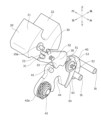
- 1 is a perspective view of a latch device;
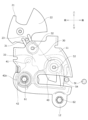
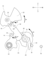
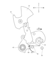
- FIG. 4 is a perspective view of the latch device, showing a state in which the housing is removed; It is an exploded perspective view of a latch device. It is a front view of a latch device. FIG. 4 is a front view of the latch device, showing a state in which the housing is removed; It is a side view of a latch device. It is a rear view of a latch device. It is a figure which shows the unlocked state in the releasing position of a latch device. It is a figure which shows the locked state in the intermediate position of a latch device. It is a figure which shows the unlocked state in the intermediate position of a latch device. It is a figure which shows the unlocked state in the engagement position of a latch device.
- FIG. 11 is a front view of a latch device of Modification 1;
- FIG. 11 is a rear view of a latch device of Modification 2;
- 1 is a schematic diagram showing a vehicle having a vehicle body provided with a latch device and a vehicle seat provided with a striker;
- a vehicle V which is a four-wheeled electric vehicle (EV vehicle)
- EV vehicle a four-wheeled electric vehicle
- the vehicle V may be not only a four-wheeled electric vehicle, but also an engine vehicle, a hybrid vehicle equipped with both a motor and an engine for running, a vehicle equipped with a battery and a fuel cell as power sources, or the like.
- longitudinal direction means the longitudinal direction when the occupant is seated on the vehicle seat S.
- inner and outer directions refers to a left-right direction when an occupant of the vehicle V and vehicle seat S is seated on the vehicle seat S and looking forward, or a direction that coincides with the width direction of the seat (seat back S2).
- vertical direction is the vertical direction of the vehicle V, and is the direction that coincides with the vertical direction when the vehicle V is running on a horizontal plane.
- a vehicle V includes a vehicle seat S on which an occupant sits, and a latch device L that fixes the vehicle seat S to a vehicle body (vehicle inner wall B).
- the vehicle seat S includes a seat cushion S1 and a seat back S2 rotatably attached to the seat cushion S1.
- the latch device L is provided on the vehicle seat S and engages with the striker St installed on the inner wall B of the vehicle body. Specifically, the latch device L is attached to an outer attachment portion S2a of the seat back S2 in the inward/outward direction (seat width direction) at a position facing the inner wall B of the vehicle body.
- the striker St is a U-shaped engaging member that is installed on the vehicle body inner wall B of the vehicle V and protrudes inward from the vehicle body inner wall B in the inward and outward directions.
- the latch device L can fix the vehicle seat S to the vehicle body inner wall B by being engaged with the striker St.
- the latch device L is configured to be engageable with the striker St at the position shown in FIG. 1A or 1B, and has a function of adjusting the tilt position of the seatback S2. Further, the latch device L has a function of allowing the seat back S2 to fall down as shown in FIG. 1C by disengaging from the striker St.
- FIG. 1A shows a locked state in which the latch device L is engaged with the striker St at the engaging position where the seatback S2 is most inclined.
- FIG. 1B shows a locked state in which the latch device L is engaged with the striker St at the intermediate position of the seatback S2.
- FIG. 1C shows an unlocked state (lock-off state) in which the latch device L is disengaged from the striker St at the release position where the latch device L is disengaged from the striker St.
- the latch device L includes a housing 10 attached to the seatback S2, an unlocking operation knob 20 operated by an occupant, a link 30 operated by the unlocking operation knob 20, a latch 40 engaged with the striker St, It mainly includes a lock-off detection sensor 50 that detects a locked state of the latch device L with respect to the striker St, and a fixture 60 that fixes the latch device L to the seatback S2.
- the latch device L is fixed to the seat back S2 of the vehicle seat S with a fastener 60 such as a bolt.
- the housing 10 is a cover member made of resin that covers the link 30, the latch 40, and the lock-off detection sensor 50 from the outside.
- the housing 10 includes a housing main body 11 that accommodates the latch 40 and the lock-off detection sensor 50 therein, and a flange 12 for attaching the housing 10 to the vehicle seat S.
- the housing 10 is mounted inside the mounting portion S2a by means of fixtures 60 (first fixtures 61 and second fixtures 62), and is positioned to cover the outside of the latch 40 and the lock-off detection sensor 50. As shown in FIG.
- the housing main body 11 has a flat plate-like base portion 11a and rib portions 11b that bend inward in the inward and outward directions from the base portion 11a. Further, the housing body 11 includes a latch shaft hole 11c that supports the latch 40, a link shaft hole 11d that supports the link 30, a sensor shaft hole 11e that supports the lock-off detection sensor 50, and a striker. A receiving groove 11f for receiving St is formed.
- the base portion 11a is arranged at a position overlapping the latch 40 and the lock-off detection sensor 50 in the inward and outward directions, as shown in FIG.
- the rib portion 11 b is arranged at a position overlapping the side surfaces in the front-rear direction and the lower surfaces in the vertical direction of the latch 40 and the lock-off detection sensor 50 . Since the space is formed inside by the base portion 11a and the rib portion 11b, the housing body portion 11 can accommodate the latch 40 and the lock-off detection sensor 50 therein. Therefore, the size of the latch device L can be reduced. In addition, it is possible to prevent parts such as the link 30, the latch 40, and the lock-off detection sensor 50 from interfering with the pad material or the like of the vehicle seat S arranged around the latch device L.
- the housing main body 11 can restrict the movement of the latch 40 to the outside of the housing main body 11 by forming the rib portion 11b around the latch 40 . Further, the housing main body 11 can increase the rigidity of the housing main body 11 by integrally forming the rib portion 11b with the base portion 11a.
- the latch shaft hole 11c is formed in the upper portion of the housing main body 11 so as to pass through the base portion 11a in the inward and outward directions.
- the latch shaft hole 11c is a first through hole that rotatably supports the latch 40 .
- the link shaft hole 11d is formed in the lower front portion of the housing main body 11 so as to pass through the base portion 11a in the inward and outward directions.
- the link shaft hole 11d rotatably supports the link 30.
- the sensor shaft hole 11e is formed in the rear portion of the housing main body 11 so as to pass through the base portion 11a in the inner and outer directions.
- the sensor shaft hole 11e rotatably supports the lock-off detection sensor 50. As shown in FIG.
- the receiving groove 11f is formed by notching forward from the rear end portion slightly below the intermediate portion of the length of the housing body 11 in the vertical direction.
- the receiving groove 11f receives the striker St entering the housing 10 when the latch device L is operated.
- the flange 12 is a thin plate-like fixing portion provided at the lower end portion of the housing main body portion 11 .
- the flange 12 is formed with a mounting hole 12a, which is a second through hole.
- the latch device L is fixed to the seat back S2 by a first fixture 61 inserted through the latch shaft hole 11c of the housing body 11 and a second fixture 62 inserted through the mounting hole 12a. be done.
- the tightening torque of the first fixture 61 is higher than the tightening torque of the second fixture 62 . In this manner, the latch device L can be attached more firmly to the latch shaft hole 11c corresponding to the rotation shaft of the latch 40.
- the thickness of the flange 12 is smaller than the thickness of the housing main body 11 . That is, the length of the fixture 60 required to fix the latch device L to the vehicle seat S is longer than that of the second fixture 62 inserted through the mounting hole 12 a of the flange 12 . It is shorter than the first fixture 61 inserted through the shaft hole 11c. Therefore, attaching the fasteners 60 to the thin flange 12 can reduce the length of the bolt rather than attaching a plurality of fasteners 60 to the thick housing body 11 . In other words, when fixing at two points, the housing main body 11 and the flange 12, the number of bolts can be reduced while ensuring fixing strength.
- the unlock operation knob 20 is an operation member for changing the latch 40 from the locked state to the unlocked state. As shown in FIGS. 2 to 6, the unlocking operation knob 20 has an operating portion 21 operated by the passenger, an indicator 22 indicating the position of the latch 40, and the operation of the unlocking operation knob 20 to the link 30. It mainly has pins 23 and .
- the lock release operation knob 20 is made of resin, for example, and is formed as a single member by integrally molding an operation portion 21, an indicator 22, and a pin 23. As shown in FIG. By manufacturing resin parts by integral molding, it is possible to reduce the number of parts, manufacturing man-hours, and costs while maintaining the weight.
- the unlocking operation knob 20 is rotatably provided on the mounting portion S2a of the seatback S2 by an operation shaft portion 20a.
- the operation part 21 is a part operated by the passenger when displacing the latch 40 from the locked state to the unlocked state. As shown in FIGS. 2 to 6, the operation part 21 is rotated by being pulled up, and releases the engagement between the latch 40 and the striker St via the pin 23 and the link 30 .
- the indicator 22 is a part that indicates the locked state and the unlocked state of the latch 40 .
- a part of the indicator 22 is provided at a position visible from the outside of the attachment portion S2a when attached to the seat back S2.
- the visible portion is colored red or the like so as to stand out. Therefore, the indicator 22 indicates the unlocked state at the position where the colored portion is exposed from the mounting portion S2a and visible, and indicates the locked state at the position where the colored portion is invisible. do.
- the pin 23 is a portion that is displaced when the operating portion 21 is pulled up.
- the pin 23 is provided at a lower portion of the unlocking operation knob 20 at a position where it engages with the link 30 .
- Pin 23 displaces latch 40 through engaging link 30 .
- each of the locked state and unlocked state of the latch 40 transmitted from the link 30 is transmitted to the indicator 22 .
- the pin 23 in the unlocking operation knob 20 By providing the pin 23 in the unlocking operation knob 20 in this manner, the number of parts can be reduced, and the manufacturing man-hours and cost can be reduced. Further, by integrally molding the pin 23 with the same material as the unlocking operation knob 20, the number of parts, manufacturing man-hours, and cost can be reduced. Further, the unlocking operation knob 20 integrally forms the operating portion 21, the indicator 22, and the pin 23, and the locked state and the unlocked state can be visually confirmed by the position of the indicator 22, so that the latch 40 can be locked with a simple structure. You can check the status and unlock status.
- the link 30 is a link member that transmits the operations of the unlocking operation knob 20 and the latch 40 .
- the link 30 is a plate-shaped metal member, and as shown in FIGS. , and an abutment portion 33 that abuts against the latch 40 .
- the link shaft portion 32 and the contact portion 33 are provided at positions overlapping the housing main body portion 11 in the inside and outside directions. As described above, since a part of the link 30 is covered with the housing main body 11, the pad material or the like of the vehicle seat S arranged around the latch device L and the link 30 can be prevented from interfering with each other. can be suppressed.
- the link 30 is rotated via the pin 23 by pulling up the operation portion 21 of the lock release operation knob 20 . As the link 30 rotates, the engagement between the latch 40 and the striker St is released. Link 30 also communicates the locked and unlocked states of latch 40 to indicator 22 via pin 23 . Specifically, when the latch 40 is in the unlocked state (FIGS. 9A, 9C, and 9D), the latch 40 abuts against the abutting portion 33 so that the engaging portion 31 moves around the link shaft portion 32. , and the indicator 22 rotates upward via the pin 23 . When the latch 40 is in the locked state (FIGS. 9B and 9E), the contact between the latch 40 and the contact portion 33 is released, so that the engaging portion 31 rotates about the link shaft portion 32. Indicator 22 rotates downward via pin 23 .
- the engaging portion 31 is provided at the end of the link 30 on the unlocking operation knob 20 side, and is positioned to engage with the pin 23 .
- One end of the engaging portion 31 on the pin 23 side is formed in an open U shape.
- the engagement portion 31 is formed in a U-shape with one end portion open, so that the lock release operation knob 20 and the link 30 can be assembled. can improve sexuality.
- the link shaft portion 32 is rotatably supported in the link shaft hole 11d of the housing main body portion 11, as shown in FIG. As shown in FIG. 8, a spiral spring 32a is provided inside the link shaft portion 32 in the in-and-out direction. The link 30 is urged by the spiral spring 32a in a direction in which the engaging portion 31 rotates downward.
- the contact portion 33 rotates forward about the link shaft portion 32 and contacts the latch 40 when the unlocking operation knob 20 is operated.
- the abutment of the abutment portion 33 causes the latch 40 to rotate forward, and the engagement between the latch 40 and the striker St is released.
- the latch 40 is a locking member that engages with the striker St to lock the position of the seatback S2.
- the latch 40 is a plate-like member made of metal, for example, and is provided inside the housing main body 11 . As shown in FIGS. 3 to 6, the latch 40 has a contact portion 41 that contacts the link 30, a latch shaft portion 42 pivotally supported by the housing body portion 11, and an engagement portion that engages with the striker St. It has a groove 43 , an escape groove 44 into which the striker St enters, and a sensor contact pin 45 that contacts the lock-off detection sensor 50 .
- the latch 40 is provided at a position overlapping the housing body 11 in the inside and outside directions. Since the latch 40 is covered with the housing main body 11 in this way, it is possible to prevent the latch 40 from interfering with the pad material or the like of the vehicle seat S arranged around the latch device L.
- the latch 40 is rotatably supported by the housing main body 11 and can transition between a locked state in which it is engaged with the striker St and an unlocked state in which it is disengaged from the striker St. Specifically, when the lock release operation knob 20 is pulled up, it is rotated upward via the link 30 . Then, when the unlocking operation knob 20 is lowered at the intermediate position or the engaged position, it is rotated downward via the link 30 . Also, the latch 40 communicates the locked state and the unlocked state to the indicator 22 via the link 30 .
- the contacted portion 41 is provided at the upper end of the latch 40 and protrudes outward.
- the abutted portion 41 is rotated upward and forward by the abutment of the abutting portion 33, and the engagement between the engaging groove 43 and the striker St is released.
- the latch shaft 42 is provided at the front end of the latch 40 and protrudes outward.
- the latch shaft portion 42 is rotatably supported in the latch shaft hole 11 c of the housing main body portion 11 .
- a coil spring 42a is provided outside the latch shaft portion 42 and inside the housing body portion 11, as shown in FIG.
- the latch 40 is biased by a coil spring 42a in a direction in which the engagement groove 43 and the escape groove 44 rotate downward.
- the engaging groove 43 is provided at the rear end of the latch 40 and is formed by notching upward from the lower end. At the intermediate position (FIG. 9B), the engaging groove 43 is engaged with the front striker St to be locked. At the engaging position (FIG. 9E), the engaging groove 43 is engaged with the rear striker St to be locked.
- the escape groove 44 is provided in the middle portion of the latch 40 in the front-rear direction, and is formed by notching upward from the lower end portion. In the engagement position (FIG. 9E), the escape groove 44 is penetrated by the forward striker St.
- the sensor contact pin 45 is provided at the upper end of the intermediate portion of the latch 40 in the front-rear direction and protrudes outward.
- the sensor contact pin 45 contacts the lock-off detection sensor 50 (sensor convex portion 51 described later) in the unlocked state (lock-off state) at the unlocked position, thereby restricting the rotation of the latch 40 .
- the lock-off detection sensor 50 is a sensor member that detects an unlocked state and a lock-off state in which the striker St is outside the latch device L. As shown in FIG.
- the lock-off detection sensor 50 is a plate-like member in the shape of a tortoise, and is provided inside the housing main body 11 .
- the lock-off detection sensor 50 includes a sensor convex portion 51 that contacts the sensor contact pin 45, a sensor shaft portion 52 that is pivotally supported by the housing main body portion 11, and a housing main body. It has a housing contact portion 53 that contacts the portion 11 and a striker detection portion 54 that contacts the striker St.
- the lock-off detection sensor 50 is provided at a position overlapping the housing main body 11 in the inside and outside directions. Since the lock-off detection sensor 50 is housed inside the housing main body 11 in this way, the pad material of the vehicle seat S or the like arranged around the latch device L interferes with the lock-off detection sensor 50. You can prevent it from happening.
- the sensor convex portion 51 is provided on the upper side of the lock-off detection sensor 50 in the lock-off state shown in FIG.
- the sensor protrusion 51 contacts the sensor contact pin 45 of the latch 40 in the unlocked state, thereby restricting the downward rotation of the latch 40 .
- the sensor shaft portion 52 is provided in the front center portion of the lock-off detection sensor 50 and is rotatably supported in the sensor shaft hole 11e of the housing main body portion 11 .
- a spiral spring 52a is provided inside the sensor shaft portion 52, as shown in FIG.
- the lock-off detection sensor 50 is biased by a spiral spring 52a in a direction in which the sensor protrusion 51 rotates forward.
- the housing contact portion 53 is a portion that is provided around the sensor shaft portion 52 and contacts the base portion 11a of the housing body portion 11 of the housing body portion 11 . As shown in FIGS. 3 and 7, the housing contact portion 53 is formed with a step so as to be located outside the striker detection portion 54 in the inside-outside direction.
- the striker detection portion 54 is an elongated member extending downward from the housing contact portion 53 in the lock-off state shown in FIG. Specifically, in the lock-off state, the striker detection part 54 curves and extends in the opposite direction (front side) to the direction in which it contacts the striker St. Further, when the striker St has entered the latch device L (see FIGS. 8 and 9E), the striker detection portion 54 extends forward from the housing contact portion 53 by coming into contact with the striker St. is rotated to the position where
- the sensor contact pin 45 of the latch 40 rides on the sensor protrusion 51, and the unlocking operation knob 20 cannot return to its original position, resulting in a state in which the unlocking operation knob 20 is half raised. , the indicator 22 indicates that the lock is off.
- the locked state see FIG. 9B
- the sensor contact pin 45 is inserted under the sensor convex portion 51, and the unlocking operation knob 20 returns to its original position, so that the indicator 22 is lowered and hidden. Is displayed.
- the lock-off state of the latch device L can be detected by the position of the striker detection portion 54 .
- the latch 40 is rotatably supported by the housing main body 11 by a latch shaft portion 42 .
- the housing contact portion 53 is rotatably supported by the housing main body portion 11 by the sensor shaft portion 52 .
- the striker detection portion 54 is arranged between the latch 40 and the housing contact portion 53 in the axial direction (inward and outward directions) in which the latch 40 and the housing contact portion 53 are pivotally supported by the housing body portion 11. . Since the striker detection section 54 is provided at a position spaced inward from the housing main body section 11 in this manner, the striker detection section 54 and members provided around the latch device L do not interfere with each other. can be suppressed.
- the housing 10 includes a plurality of biasing members (spiral spring 32a, coil It has a spring 42a and a spiral spring 52a).
- a spiral spring can reduce the thickness of the spring compared to a coil spring without affecting the number of turns or the diameter of the spring core. Therefore, by using a spiral spring for at least one of the plurality of biasing members, the size of the latch device L can be reduced.
- FIG. 9A shows an unlocked state (lock-off state) in which the latch device L is in the released position and the latch 40 is not engaged with the striker St.
- the operation portion 21 of the lock release operation knob 20 is pulled up in the direction of arrow A1 from the locked state, the engagement portion 31 is rotated in the direction of arrow A2 via the pin 23 .
- the abutment portion 33 abuts on the abutted portion 41 of the latch 40 by rotating in the arrow A3 direction about the link shaft portion 32 .
- the latch 40 is rotated in the direction of the arrow A4, and the engagement groove 43 is brought into a lock-off state in which the engagement with the striker St is released.
- FIG. 9B shows a first stage locked state in which the latch device L is in the middle position and the engagement groove 43 of the latch 40 is engaged with the forward striker St.
- the engaging portion 31 is rotated in the arrow B2 direction by the biasing force of the spiral spring 32a.
- the unlocking operation knob 20 is rotated by the pin 23 in the direction of the arrow B1.
- the abutment portion 33 is released from the abutment with the abutted portion 41 of the latch 40 by rotating in the arrow B3 direction about the link shaft portion 32 .
- FIG. 9C shows a first stage unlocked state in which the latch device L is in the intermediate position and the latch 40 is not engaged with the striker St.
- FIG. 9D shows a second stage unlocked state in which the latch device L is in the engaged position and the latch 40 is not engaged with the striker St.
- FIG. 9E shows a second stage locked state in which the engagement groove 43 of the latch 40 is engaged with the rear striker St at the engagement position of the latch device L.
- FIG. 9D From the state of FIG. 9D, the engaging portion 31 is rotated in the direction of arrow E2 by the biasing force of the spiral spring 32a. At this time, the unlocking operation knob 20 is rotated in the direction of the arrow E1 by the pin 23. As shown in FIG. Then, the abutment portion 33 is released from the abutment with the abutted portion 41 of the latch 40 by rotating in the direction of the arrow E3 about the link shaft portion 32 .
- the biasing force of the coil spring 42a rotates the latch 40 in the direction of the arrow E4, and the engagement groove 43 is engaged with the rear striker St to enter the second stage locked state. Also, the front striker St enters the escape groove 44 . At this time, the lock-off detection sensor 50 maintains the rotated state shown in FIG. 9D because the striker detection portion 54 comes into contact with the forward striker St.
- the latch 40 can be transitioned between the locked state and the unlocked state with a simple structure via the pin 23 provided on the unlocking operation knob 20, and the indicator 22 indicates that the latch 40 is in the unlocked state. can be displayed properly. Therefore, the number of parts, manufacturing man-hours, and cost can be reduced compared to the case where the unlocking operation knob 20 and the pin 23 are separate parts.
- Modification 1 of the latch device L will be described with reference to FIG. Note that the description of the contents overlapping with the latch device L described above will be omitted (same below).
- the housing 10 of the latch device L of Modification 1 has a housing main body 11, a flange 12 for attaching the housing 10, and a fixed flange 13.
- the fixed flange 13 is a thin plate-like fixing portion provided at the upper rear end portion of the housing main body portion 11 .
- the fixed flange 13 is formed with a fixed mounting hole 13a which is a third through hole.
- the latch device L of Modification 1 includes a first fixture 61 inserted through the latch shaft hole 11c of the housing body 11, a second fixture 62 inserted through the mounting hole 12a, and a second fixture 62 inserted through the fixed mounting hole 13a. It is fixed to the vehicle seat S by the 3 fixtures 63 .
- Modification 2 of the latch device L will be described with reference to FIG.
- the latch device L of Modification 2 is provided with a spiral spring 42b inside the latch shaft portion 42.
- the latch 40 is biased by a spiral spring 42b in a direction in which the engaging groove 43 and the escape groove 44 rotate downward.
- spiral springs can reduce the thickness of the spring without affecting the number of turns or the diameter of the spring core. Therefore, by using the spiral spring 42b, the size of the latch device L can be further reduced.
- the striker St is installed on the inner wall B of the vehicle body, and the latch device L is attached to the seat back S2. It can be attached to the site. Also, the place where the striker St is attached is not limited to the inner wall B of the vehicle body, and may be another part of the vehicle body such as the floor. For example, as shown in FIG. 12, the latch device L may be attached to the inner wall B of the vehicle body, and the striker St may be attached to the attachment portion S2a of the seatback S2.
- the latch device, vehicle seat, and vehicle according to the present invention have been mainly described.
- the above embodiment is merely an example for facilitating understanding of the present invention, and does not limit the present invention.
- the present invention can be modified and improved without departing from its spirit, and the present invention includes equivalents thereof.
Landscapes
- Engineering & Computer Science (AREA)
- Aviation & Aerospace Engineering (AREA)
- Transportation (AREA)
- Mechanical Engineering (AREA)
- Lock And Its Accessories (AREA)
- Seats For Vehicles (AREA)
Priority Applications (4)
| Application Number | Priority Date | Filing Date | Title |
|---|---|---|---|
| US18/842,946 US20250162474A1 (en) | 2022-03-01 | 2023-02-28 | Latch device, vehicle seat, and vehicle |
| JP2024504699A JPWO2023167194A1 (https=) | 2022-03-01 | 2023-02-28 | |
| EP23763451.4A EP4488114A4 (en) | 2022-03-01 | 2023-02-28 | LOCKING DEVICE, VEHICLE SEAT AND VEHICLE |
| CN202380022253.6A CN118715134A (zh) | 2022-03-01 | 2023-02-28 | 闩锁装置、车辆用座椅及车辆 |
Applications Claiming Priority (8)
| Application Number | Priority Date | Filing Date | Title |
|---|---|---|---|
| US202263315146P | 2022-03-01 | 2022-03-01 | |
| US202263315150P | 2022-03-01 | 2022-03-01 | |
| US202263315151P | 2022-03-01 | 2022-03-01 | |
| US202263315142P | 2022-03-01 | 2022-03-01 | |
| US63/315,142 | 2022-03-01 | ||
| US63/315,151 | 2022-03-01 | ||
| US63/315,150 | 2022-03-01 | ||
| US63/315,146 | 2022-03-01 |
Publications (1)
| Publication Number | Publication Date |
|---|---|
| WO2023167194A1 true WO2023167194A1 (ja) | 2023-09-07 |
Family
ID=87883804
Family Applications (1)
| Application Number | Title | Priority Date | Filing Date |
|---|---|---|---|
| PCT/JP2023/007349 Ceased WO2023167194A1 (ja) | 2022-03-01 | 2023-02-28 | ラッチ装置、車両用シート及び車両 |
Country Status (4)
| Country | Link |
|---|---|
| US (1) | US20250162474A1 (https=) |
| EP (1) | EP4488114A4 (https=) |
| JP (1) | JPWO2023167194A1 (https=) |
| WO (1) | WO2023167194A1 (https=) |
Citations (4)
| Publication number | Priority date | Publication date | Assignee | Title |
|---|---|---|---|---|
| JPS60255511A (ja) * | 1984-05-31 | 1985-12-17 | Sumitomo Wiring Syst Ltd | タイヤのすべり止め装置 |
| DE10142486A1 (de) * | 2001-08-30 | 2003-03-20 | Witte Velbert Gmbh & Co Kg | Verschluss zum Fesseln einer Rückenlehne eines Kraftfahrzeuges an der Karosserie |
| US20050264043A1 (en) * | 2004-05-12 | 2005-12-01 | Faurecia Autositze Gmbh & Co. Kg | Release device for a rear seat backrest component part of a vehicle |
| JP2018052397A (ja) * | 2016-09-30 | 2018-04-05 | テイ・エス テック株式会社 | シート用ラッチ装置 |
Family Cites Families (34)
| Publication number | Priority date | Publication date | Assignee | Title |
|---|---|---|---|---|
| FR2720985B1 (fr) * | 1994-06-14 | 1996-09-06 | Faure France Bertrand | Système de verrouillage d'un élément mobile d'un siège de véhicule automobile. |
| DE4444122C1 (de) * | 1994-12-12 | 1996-04-11 | Daimler Benz Ag | Anzeigevorrichtung zur Signalisierung der Nichtverriegelung einer umklappbaren Rückenlehne eines Fahrzeugsitzes |
| GB2298123B (en) * | 1995-02-24 | 1998-07-01 | Rover Group | A rear seat assembly for a motor vehicle |
| FR2742389B1 (fr) * | 1995-12-19 | 1998-02-20 | Faure Bertrand Equipements Sa | Dispositif de verrouillage d'un element mobile d'un siege de vehicule automobile, avec visualisation de verrouillage |
| EP0839685B1 (en) * | 1996-02-27 | 2007-09-12 | Toyota Jidosha Kabushiki Kaisha | Lock releasing mechanism for a folding rear seatback |
| JP4429480B2 (ja) * | 2000-05-31 | 2010-03-10 | テイ・エス テック株式会社 | 車両用シートロック装置 |
| DE10328504B3 (de) * | 2003-06-18 | 2004-12-09 | Keiper Gmbh & Co. Kg | Entriegelungsvorrichtung für einen Fahrzeugsitz |
| US7377584B2 (en) * | 2003-07-28 | 2008-05-27 | Johnson Controls Technology Company | Articulating high latch for a seat |
| US20060108847A1 (en) * | 2004-03-02 | 2006-05-25 | O'callaghan Timothy S | Seat latch and latching method |
| DE102004045988B3 (de) * | 2004-09-22 | 2005-12-01 | Faurecia Autositze Gmbh & Co. Kg | Anzeige zur Signalisierung der Nichtverriegelung einer klappbaren Rückenlehne eines Kraftfahrzeugsitzes |
| DE102004057338A1 (de) * | 2004-11-27 | 2006-06-01 | Bayerische Motoren Werke Ag | Schloss, insbesondere für ein Kraftfahrzeug |
| DE102008033305B4 (de) * | 2008-07-11 | 2019-06-27 | Adient Luxembourg Holding S.À R.L. | Verriegelungsvorrichtung für einen Fahrzeugsitz und Fahrzeugsitz |
| DE102008033304B4 (de) * | 2008-07-11 | 2018-01-04 | Adient Luxembourg Holding S.à.r.l. | Verriegelungsvorrichtung für einen Fahrzeugsitz und Fahrzeugsitz |
| DE102008033303B4 (de) * | 2008-07-11 | 2015-08-20 | Johnson Controls Components Gmbh & Co. Kg | Verriegelungsvorrichtung für einen Fahrzeugsitz |
| JP5414108B2 (ja) * | 2009-09-04 | 2014-02-12 | スズキ株式会社 | 自動車のシートバックのロック装置 |
| DE102009056155B4 (de) * | 2009-11-25 | 2017-03-09 | Johnson Controls Components Gmbh & Co. Kg | Anzeigevorrichtung |
| JP5574219B2 (ja) * | 2010-01-15 | 2014-08-20 | スズキ株式会社 | シートバックにおけるロック解除ノブ機構のインジケータ構造 |
| JP5663671B2 (ja) * | 2011-02-03 | 2015-02-04 | ジョンソン コントロールズ コンポーネンツ ゲーエムベーハー ウントコンパニー カーゲー | 車両シート用作動器及び継手システム |
| DE102011018330B4 (de) * | 2011-04-18 | 2014-05-22 | Keiper Gmbh & Co. Kg | Betätigungseinheit für einen Fahrzeugsitz |
| DE102011054990B4 (de) * | 2011-11-02 | 2021-05-27 | Witte Automotive Gmbh | Rückenlehnenverriegelung mit Anzeigeglied |
| DE102012003333A1 (de) * | 2011-11-04 | 2013-05-08 | Keiper Gmbh & Co. Kg | Abschließbare Verriegelungsvorrichtung für einen Fahrzeugsitz und Fahrzeugsitz |
| DE102012020269B4 (de) * | 2012-07-31 | 2021-01-07 | Adient Luxembourg Holding S.À R.L. | Verriegelungsvorrichtung für einen Fahrzeugsitz und Fahrzeugsitz |
| DE102012107185A1 (de) * | 2012-08-06 | 2014-02-06 | Witte Automotive Gmbh | Riegelverschluss für Kraftfahrzeugtüren, -sitze oder -rückenlehnen mit Klapperschutz |
| JP5982687B2 (ja) * | 2012-10-31 | 2016-08-31 | 三井金属アクト株式会社 | シートロック装置 |
| DE102013202010A1 (de) * | 2013-02-07 | 2014-08-07 | GM Global Technology Operations LLC (n. d. Gesetzen des Staates Delaware) | Schloss |
| DE102013216220B3 (de) * | 2013-06-28 | 2014-12-04 | Johnson Controls Components Gmbh & Co. Kg | Verriegelungseinheit für einen Fahrzeugsitz und Fahrzeugsitz |
| DE102014112031A1 (de) * | 2014-08-22 | 2016-02-25 | Witte Automotive Gmbh | Schloss |
| DE102016205485A1 (de) * | 2016-04-04 | 2017-10-05 | Volkswagen Aktiengesellschaft | Betätigungsvorrichtung zur Lehnenentriegelung mit zwei Betätigungselementen und einem Indikator zur Anzeige der Lehnenverriegelung |
| JP6687221B2 (ja) * | 2017-05-30 | 2020-04-22 | 三井金属アクト株式会社 | シートロック装置 |
| WO2018220726A1 (ja) * | 2017-05-30 | 2018-12-06 | 三井金属アクト株式会社 | シートロック装置 |
| CN110891824B (zh) * | 2017-07-13 | 2022-06-14 | 三井金属爱科特株式会社 | 座锁定装置 |
| KR102286446B1 (ko) * | 2019-11-26 | 2021-08-05 | 현대트랜시스 주식회사 | 차량 시트용 폴딩 레버 장치 |
| GB2594724B (en) * | 2020-05-05 | 2022-10-12 | Jaguar Land Rover Ltd | Apparatus for retaining a seat belt |
| DE102023134965A1 (de) * | 2023-01-30 | 2024-08-01 | Adient Us Llc | Verriegelungsvorrichtung für einen fahrzeugsitz, adapteranordnung zur anbindung einer verriegelungsvorrichtung, sowie fahrzeugsitz |
-
2023
- 2023-02-28 US US18/842,946 patent/US20250162474A1/en active Pending
- 2023-02-28 JP JP2024504699A patent/JPWO2023167194A1/ja active Pending
- 2023-02-28 EP EP23763451.4A patent/EP4488114A4/en active Pending
- 2023-02-28 WO PCT/JP2023/007349 patent/WO2023167194A1/ja not_active Ceased
Patent Citations (4)
| Publication number | Priority date | Publication date | Assignee | Title |
|---|---|---|---|---|
| JPS60255511A (ja) * | 1984-05-31 | 1985-12-17 | Sumitomo Wiring Syst Ltd | タイヤのすべり止め装置 |
| DE10142486A1 (de) * | 2001-08-30 | 2003-03-20 | Witte Velbert Gmbh & Co Kg | Verschluss zum Fesseln einer Rückenlehne eines Kraftfahrzeuges an der Karosserie |
| US20050264043A1 (en) * | 2004-05-12 | 2005-12-01 | Faurecia Autositze Gmbh & Co. Kg | Release device for a rear seat backrest component part of a vehicle |
| JP2018052397A (ja) * | 2016-09-30 | 2018-04-05 | テイ・エス テック株式会社 | シート用ラッチ装置 |
Non-Patent Citations (1)
| Title |
|---|
| See also references of EP4488114A4 * |
Also Published As
| Publication number | Publication date |
|---|---|
| JPWO2023167194A1 (https=) | 2023-09-07 |
| US20250162474A1 (en) | 2025-05-22 |
| EP4488114A1 (en) | 2025-01-08 |
| EP4488114A4 (en) | 2025-10-29 |
Similar Documents
| Publication | Publication Date | Title |
|---|---|---|
| JP4597058B2 (ja) | 車両用シートロック装置 | |
| US6039400A (en) | Seat reclining device | |
| US6123379A (en) | Locking mechanism for vehicles | |
| US20220332224A1 (en) | Locking device for walk-in seat of vehicle | |
| EP1606137B1 (en) | Seat back recliner for vehicles | |
| EP2537705B1 (en) | Lock mechanism for automobile rear seat | |
| US8104834B2 (en) | Automatic seat cushion locking mechanism with automatic tip-up | |
| JPH10102864A (ja) | ロック装置 | |
| JP6291607B1 (ja) | ロック解除レバー取付構造 | |
| JP6691313B2 (ja) | ラッチ装置および乗物用シート | |
| US5678895A (en) | Reclining device for seat | |
| US8882161B2 (en) | Locking device with signal structure | |
| US7517021B2 (en) | Reclining mechanism for vehicle seats | |
| WO2011030734A1 (ja) | 車両用シートの収納装置 | |
| JP2018052395A (ja) | 乗物用ラッチ装置 | |
| US10843589B2 (en) | Locking device for vehicle seat | |
| WO2023167194A1 (ja) | ラッチ装置、車両用シート及び車両 | |
| JP2007196718A (ja) | 車両用シートロック装置 | |
| CN118715134A (zh) | 闩锁装置、车辆用座椅及车辆 | |
| JP4608442B2 (ja) | 車両用シートロック装置 | |
| JP2007196717A (ja) | 車両用シートロック装置 | |
| JP4126876B2 (ja) | シートスライド装置 | |
| JP2016037057A (ja) | ヘッドレストおよびシート | |
| US20250091486A1 (en) | Functional unit for adjusting a seat back of a vehicle seat and vehicle seat | |
| JP7602128B2 (ja) | 乗物用ラッチ装置、乗物用シート、および、乗物用ラッチ装置の製造方法 |
Legal Events
| Date | Code | Title | Description |
|---|---|---|---|
| 121 | Ep: the epo has been informed by wipo that ep was designated in this application |
Ref document number: 23763451 Country of ref document: EP Kind code of ref document: A1 |
|
| WWE | Wipo information: entry into national phase |
Ref document number: 2024504699 Country of ref document: JP |
|
| WWE | Wipo information: entry into national phase |
Ref document number: 202380022253.6 Country of ref document: CN |
|
| WWE | Wipo information: entry into national phase |
Ref document number: 18842946 Country of ref document: US |
|
| WWE | Wipo information: entry into national phase |
Ref document number: 2023763451 Country of ref document: EP |
|
| NENP | Non-entry into the national phase |
Ref country code: DE |
|
| ENP | Entry into the national phase |
Ref document number: 2023763451 Country of ref document: EP Effective date: 20241001 |
|
| WWP | Wipo information: published in national office |
Ref document number: 18842946 Country of ref document: US |