WO2023145786A1 - 連続鋳造のスタートタイミング判定方法、連続鋳造設備の操業方法、鋳片の製造方法、判定装置、連続鋳造スタート判定システム及び表示端末装置 - Google Patents
連続鋳造のスタートタイミング判定方法、連続鋳造設備の操業方法、鋳片の製造方法、判定装置、連続鋳造スタート判定システム及び表示端末装置 Download PDFInfo
- Publication number
- WO2023145786A1 WO2023145786A1 PCT/JP2023/002318 JP2023002318W WO2023145786A1 WO 2023145786 A1 WO2023145786 A1 WO 2023145786A1 JP 2023002318 W JP2023002318 W JP 2023002318W WO 2023145786 A1 WO2023145786 A1 WO 2023145786A1
- Authority
- WO
- WIPO (PCT)
- Prior art keywords
- continuous casting
- determination
- casting
- start timing
- molten steel
- Prior art date
Links
- 238000009749 continuous casting Methods 0.000 title claims abstract description 126
- 238000000034 method Methods 0.000 title claims abstract description 96
- 238000004519 manufacturing process Methods 0.000 title claims abstract description 6
- 238000005266 casting Methods 0.000 claims abstract description 144
- 229910000831 Steel Inorganic materials 0.000 claims abstract description 78
- 239000010959 steel Substances 0.000 claims abstract description 78
- RYGMFSIKBFXOCR-UHFFFAOYSA-N Copper Chemical compound [Cu] RYGMFSIKBFXOCR-UHFFFAOYSA-N 0.000 claims abstract description 61
- 229910052802 copper Inorganic materials 0.000 claims abstract description 61
- 239000010949 copper Substances 0.000 claims abstract description 61
- 238000005259 measurement Methods 0.000 claims abstract description 27
- 239000002184 metal Substances 0.000 claims abstract description 26
- 229910052751 metal Inorganic materials 0.000 claims abstract description 26
- 239000000155 melt Substances 0.000 claims description 15
- XLYOFNOQVPJJNP-UHFFFAOYSA-N water Substances O XLYOFNOQVPJJNP-UHFFFAOYSA-N 0.000 claims description 10
- 230000008569 process Effects 0.000 description 45
- 238000009529 body temperature measurement Methods 0.000 description 7
- 238000010586 diagram Methods 0.000 description 7
- 238000012545 processing Methods 0.000 description 6
- 238000004364 calculation method Methods 0.000 description 4
- 238000001816 cooling Methods 0.000 description 4
- 230000004048 modification Effects 0.000 description 4
- 238000012986 modification Methods 0.000 description 4
- 238000011144 upstream manufacturing Methods 0.000 description 4
- 238000002347 injection Methods 0.000 description 3
- 239000007924 injection Substances 0.000 description 3
- 238000009434 installation Methods 0.000 description 3
- 239000000463 material Substances 0.000 description 3
- 239000013307 optical fiber Substances 0.000 description 3
- 230000007704 transition Effects 0.000 description 3
- 230000005856 abnormality Effects 0.000 description 2
- 239000000498 cooling water Substances 0.000 description 2
- 230000002950 deficient Effects 0.000 description 2
- 230000003111 delayed effect Effects 0.000 description 2
- 238000001514 detection method Methods 0.000 description 2
- 238000007654 immersion Methods 0.000 description 2
- 230000000630 rising effect Effects 0.000 description 2
- 230000002159 abnormal effect Effects 0.000 description 1
- 238000005452 bending Methods 0.000 description 1
- 230000008859 change Effects 0.000 description 1
- 238000004590 computer program Methods 0.000 description 1
- 230000007423 decrease Effects 0.000 description 1
- 238000009826 distribution Methods 0.000 description 1
- 238000000605 extraction Methods 0.000 description 1
- 230000010365 information processing Effects 0.000 description 1
- 230000000977 initiatory effect Effects 0.000 description 1
- 230000014759 maintenance of location Effects 0.000 description 1
- 230000005499 meniscus Effects 0.000 description 1
- 238000011017 operating method Methods 0.000 description 1
- 230000004044 response Effects 0.000 description 1
- 238000007711 solidification Methods 0.000 description 1
- 230000008023 solidification Effects 0.000 description 1
- 238000003756 stirring Methods 0.000 description 1
Images


Classifications
-
- B—PERFORMING OPERATIONS; TRANSPORTING
- B22—CASTING; POWDER METALLURGY
- B22D—CASTING OF METALS; CASTING OF OTHER SUBSTANCES BY THE SAME PROCESSES OR DEVICES
- B22D11/00—Continuous casting of metals, i.e. casting in indefinite lengths
- B22D11/08—Accessories for starting the casting procedure
-
- B—PERFORMING OPERATIONS; TRANSPORTING
- B22—CASTING; POWDER METALLURGY
- B22D—CASTING OF METALS; CASTING OF OTHER SUBSTANCES BY THE SAME PROCESSES OR DEVICES
- B22D11/00—Continuous casting of metals, i.e. casting in indefinite lengths
- B22D11/16—Controlling or regulating processes or operations
Definitions
- the present invention relates to a continuous casting start timing determination method, a continuous casting facility operating method, a slab manufacturing method, a determination device, a continuous casting start determination system, and a display terminal device.
- molten steel is continuously poured from a tundish and cooled in a mold with water cooling pipes embedded. manufactured.
- a dummy bar is inserted into the lower opening of the mold, molten steel is injected into the mold with the dummy bar head as the bottom surface, and after the molten steel reaches a predetermined level, the dummy bar is pulled out. Casting begins.
- Patent Document 1 focuses on the fact that the degree of solidification of the cast slab inside the mold depends on the retention time of the molten steel inside the mold from the start of molten steel pouring to the start of drawing, and detects the melt surface level using an eddy current sensor. is measured, and withdrawal is started at the timing when the withdrawal start level is reached after a preset holding time has elapsed from the start of molten steel injection.
- An object of the present invention is to provide a method, a determination device, a continuous casting start determination system, and a display terminal device.
- a continuous casting start timing determination method for determining the start timing of continuous casting comprises: , a measurement step of measuring the temperature of the copper plate using a plurality of temperature sensors provided at a casting direction determination position that is a predetermined casting direction position; a measurement result of the measurement step; and a determination step of determining the start timing according to the casting direction position of the surface of the molten steel estimated based on the width of the slab and the width of the slab.
- the threshold value C is a table value classified according to the rate of rise of the molten metal level or the rise of the molten metal level. Set based on a function of speed.
- a plurality of temperature sensors provided at at least one casting direction position different from the casting direction determination position. is used to measure the temperature of the copper plate, and in the determination step, based on the measurement result of the temperature at the at least one casting direction position and the width of the slab, at the at least one casting direction position.
- the dummy bar is pulled out, and the continuous casting is performed.
- a method of operating a continuous casting facility for initiating casting is provided.
- a determination device for determining a start timing of continuous casting is a determination device for a copper plate in a mold of the continuous casting facility. Based on a plurality of temperature sensors provided at a casting direction determination position, which is a direction position, for measuring the temperature of the copper plate, the measurement results of the plurality of temperature sensors, and the width of the slab cast by the continuous casting equipment. and a pull-out start determination unit that determines the start timing according to the casting direction position of the surface of the molten steel estimated by the method.
- a continuous casting start determination system for determining the start timing of continuous casting, which is the timing of withdrawing a dummy bar, comprises a determination server device, a display terminal device, wherein the determination server device is provided in a plurality in the width direction of the mold at a plurality of casting direction positions including a casting direction determination position which is a predetermined casting direction position in the copper plate of the mold of the continuous casting equipment, According to the casting direction position of the surface of the molten steel estimated based on the temperature sensor for measuring the temperature, the measurement results of the plurality of temperature sensors, and the width of the slab cast by the continuous casting equipment, a drawing start determination unit for determining the start timing; and a surface level information output means for outputting surface level information indicating a surface level state including the pouring direction position of the surface of the molten steel estimated by the drawing start determination unit.
- the display terminal device includes display data acquisition means for acquiring the molten metal level information, and the molten metal for each position corresponding to the temperature data of the casting direction position based on the acquired molten metal level information.
- a continuous casting start determination system comprising display means for displaying a surface state and reference data for estimating the molten metal surface state.
- a display terminal device that constitutes a continuous casting start determination system together with a determination server device that determines the start timing of continuous casting, which is the timing of withdrawing a dummy bar
- Display data acquisition means for acquiring surface level information indicating a molten steel surface level state including the casting direction position of the molten steel surface estimated by the determination server device; and a casting direction position based on the acquired molten steel surface level information and display means for displaying the molten steel surface state for each position corresponding to the temperature data of and reference data for estimating the molten steel surface state, wherein the position of the molten steel surface in the casting direction is the same as the continuous casting
- a plurality of temperature sensors are provided in the mold width direction and measure the temperature of the copper plate.
- a display terminal device is provided that is estimated by the server device
- a continuous casting start timing determination method a continuous casting facility operation method, a slab manufacturing method, a determination device, and a continuous casting start determination system that can accurately determine the start timing of continuous casting and a display terminal device are provided.
- FIG. 4 is a flowchart showing a continuous casting start timing determination method according to an embodiment of the present invention.
- FIG. 11 is an explanatory diagram showing an example of a method of displaying the status for each casting direction position in a modified example;
- 1 is a block diagram showing the configuration of a continuous casting start determination system;
- FIG. 4 is a graph showing time-series changes in temperature of the mold copper plate at casting direction determination positions in Examples.
- FIG. 4 is an explanatory diagram showing an example in which the continuous casting start timing determination method according to the present invention is applied in an embodiment.
- a continuous casting start timing determination method will be described.
- the start timing of continuous casting in the continuous casting facility 1 for continuously casting molten steel is determined.
- a cast slab is manufactured by withdrawing a dummy bar at a start timing, which will be described later, and starting continuous casting.
- the continuous casting facility 1 includes a tundish 3 into which molten steel 2 is poured, a copper mold 5 for cooling the molten steel 2 poured from the tundish 3 through an immersion nozzle 4, A plurality of slab support rolls 7 for conveying a semi-solidified slab 6 pulled out from the mold 5, a plurality of temperature sensors 8 installed on the long side surface and the short side surface of the mold 5, and the installed temperature A judgment device 9 for judging the start timing of continuous casting from the temperature detected by the sensor 8 is provided. Further, the mold 5 is provided with a coil (not shown) for generating an electromagnetic stirring magnetic field for rotating the surface of the melt.
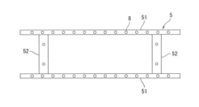
- the mold 5 is configured by sandwiching two short side copper plates 52 between two long side copper plates 51 .
- a plurality of temperature sensors 8 are provided inside the copper plate 51 and the copper plate 52 .
- a plurality of temperature sensors 8 are arranged in the horizontal direction at a plurality of positions in the casting direction of the mold 5 . That is, taking the copper plate 52 as an example as shown in FIG. 3, the temperature sensors 8 are provided at a plurality of casting direction positions with respect to the casting direction positions of the copper plate 52 (vertical direction in FIG. 3). . Also, at each casting direction position, a plurality of temperature sensors 8 are provided in the horizontal direction (horizontal direction in FIG. 3).
- the casting direction position where the temperature sensor 8 is provided is the same position for the copper plate 51 and the copper plate 52 .
- the mold 5 is configured so that the copper plate 52 on the short side can be moved in the horizontal direction in FIG. 2 so that the width of the cast slab 6 (slab width) can be adjusted.
- the temperature sensor 8 is not particularly limited as long as it can measure the temperature of the mold 5.
- a thermocouple or an optical fiber sensor may be used.
- an optical fiber is inserted from the upper end surface of the copper plates 51 and 52 in the casting direction (that is, the drawing direction) of the slab, parallel to the surface of the copper plates 51 and 52 on the molten steel side. .
- Such a method is preferably applied when the continuous casting equipment 1 is configured such that the copper plate 51 on the long side has a flat surface, such as a vertical bending slab continuous casting machine.
- the installation positions of the temperature measurement points of the temperature sensor 8 in the thickness direction of the copper plates 51 and 52 are such that the distance from the surface of the copper plates 51 and 52 on the molten steel side of all the installed temperature measurement points is the same, and each temperature measurement point is positioned between the surfaces of the copper plates 51 and 52 on the molten steel side and a cooling water slit (a channel through which cooling water passes for cooling the copper plates).
- the continuous casting facility 1 further has a determination device 9 that determines the start timing of continuous casting based on the measurement results of a plurality of temperature sensors 8, as shown in FIG.
- the determination device 9 is composed of an information processing device such as a computer, and an internal arithmetic processing device such as a CPU (Central Processing Unit) executes a computer program to operate as a hot water level estimation unit 91 and a withdrawal start determination unit 92. Function.
- the number of temperature sensors 8 provided at the same casting direction position is not particularly limited. ) is preferably 10 points or more.
- the start timing of continuous casting is determined according to the determination process of the process flow shown in FIG. 5, and continuous casting is started.
- the determination process shown in FIG. 5 is started at the timing when a start timing determination execution command is input to the determination device 9 .
- the start timing determination execution command is input by the timing of starting injection of the molten steel 2 from the submerged nozzle 4 into the mold 5 or by the operator's operation.
- step S100 the withdrawal start determination unit 92 outputs status 0 and timer 0 as initial values. There are three types of status: 0, 1, or 2. At the timing when status 2 is reached, an instruction to start pulling out the dummy bar is issued. Thereby, the process of step S100 is completed, and the determination process proceeds to the process of step S102.
- step S102 the temperatures of the copper plates 51 and 52 of the mold 5 are measured by the temperature sensor 8, and then the molten metal level estimation unit 91 obtains data on the measured temperatures of the copper plates 51 and 52 and the slab width. (measurement process). Thereby, the process of step S102 is completed, and the determination process proceeds to the process of step S104.
- the molten steel level estimation unit 91 uses the slab width data acquired in the process of step S102 and the installation coordinate data of the temperature sensors prepared in advance to The number N of temperature sensors within the width of the slab is counted.
- the mold 5 has two long side copper plates 51 and two short side copper plates 52 sandwiched between them.
- the temperature sensor 8 installed at the end of is located outside the copper plate 52 on the short side. Therefore, the temperature of the temperature sensor 8 of the copper plate 51 located outside the copper plate 52 is low even during casting. Therefore, with such a temperature sensor 8, it is difficult to determine whether the hot water surface has reached a certain level of the temperature sensor 8, and it should not be used for this determination. are pre-excluded. Thereby, the process of step S104 is completed, and the determination process proceeds to the process of step S106.
- the molten metal level estimating unit 10 detects the temperature of a plurality of temperature sensors 8 located at predetermined casting direction positions among the temperature sensors 8 extracted in the process of step S104. count the number of points m.
- the position in the casting direction is the distance from the upper ends of the copper plates 51 and 52 in the casting direction, but may be the distance in the vertical direction from the upper ends of the copper plates 51 and 52 .
- the predetermined position in the pouring direction is a position in the pouring direction that is suitable as the level of the molten metal surface in the mold 5 when continuous casting is started. is the casting direction position of This predetermined casting direction position is also referred to as a casting direction determination position. For example, in the example shown in FIG.
- the position of the fourth cut of the temperature sensor 8 from the upper end of the copper plate is defined as the pouring direction position (region indicated by the rectangular dashed line).
- N is preferably 10 points or more.
- the threshold value A is set as a value that can detect that the molten steel 2 has reached the casting direction position where the temperature sensor 8 of the copper plate 51, 52 is installed, and the distance of the temperature sensor 8 from the copper plate surface and the copper plate It is appropriately set depending on the materials of 51 and 52 and the like.
- the molten metal level estimating unit 91 determines whether the temperature of the temperature sensors 8 exceeding the threshold value A is a certain percentage or more among the plurality of temperature sensors 8 located at the casting direction determination position. That is, it is determined whether or not a value obtained by dividing the number m of sensors whose temperature exceeds the threshold A by the number N of points within the range of the slab width is equal to or greater than the threshold B. In this determination, it is determined whether or not the measured temperature is equal to or higher than a certain ratio at the casting direction determination position, thereby determining whether or not the surface of the molten steel 2 has reached the casting direction determination position. .
- step S108 if the value is less than the threshold value B, the determination process proceeds to step S110, and if the value is equal to or greater than the threshold value B, the determination process proceeds to step S112.
- the threshold value B is preferably set as a value at which it can be determined that the molten steel 2 has reached the casting direction determination position, and is set according to the detection accuracy of the temperature sensor 8 and the like.
- the molten metal surface before the start of drawing may vary greatly both in the width direction and the thickness direction. Therefore, when the threshold value B is infinitely close to 1, the timing for determining that the molten steel surface has reached the casting direction determination position is delayed, and the start of drawing is delayed, which may reduce productivity or cause molten steel to overflow from the mold. be.
- the threshold B is preferably set to a value of 0.5 or more and 0.9 or less.
- step S110 the withdrawal start determination unit 92 outputs status 0 and timer 0, and the determination process returns to the process of step S102.
- step S112 the withdrawal start determination unit 92 outputs status 1, and the determination process proceeds to the process of step S114.
- the withdrawal start determination unit 92 determines whether the timer is equal to or greater than the threshold value C. That is, in step S114, it is determined whether or not the state in which it is determined that the melt surface has reached the pouring direction determination position has continued for a predetermined time. The value of the timer indicates the duration of the state in which it is determined that the molten metal surface has reached the casting determination position. If it is less than the threshold value C, it is determined that it is not the start timing, and the determination process proceeds to step S116. On the other hand, if it is equal to or greater than the threshold value C, it is determined that it is time to start, and the determination process proceeds to step S118.
- the threshold value C is preferably set as a value at which it can be determined that a solidified shell has been sufficiently formed in the molten steel 2 that has reached the casting direction determination position to withstand the drawing.
- the threshold value C may be appropriately set based on the cooling capacity of the mold 5, past performance data, and the like. For example, from the opening of the sliding nozzle between the tundish 3 and the submerged nozzle 4 and the width and thickness of the slab, the average rate of rise of the molten metal level can be estimated. If the threshold value C is too large, molten steel may overflow from the mold.
- the threshold value C is set between 5 seconds and 15 seconds based on the function of the table value classified by the rising speed of the hot water level or the rising speed of the hot water level.
- step S116 the withdrawal start determination unit 92 outputs a value obtained by counting up the timer by one second, and the determination process returns to the process of step S102.
- temperature measurement by the temperature sensor 8 in the measurement process of step S102 is continuously performed at intervals of one second, and the series of processes from steps S102 to S116 are also performed at intervals of one second.
- step S118 the withdrawal start determination unit 92 outputs status 2, and the determination process proceeds to the process of step S120.
- the withdrawal start determination unit 92 issues a dummy bar withdrawal start instruction, and the series of determination processing ends.
- the judgment processing in steps S104 to S114 is also called a judgment step. That is, in this embodiment, the determination steps of steps S104 to S114 are performed after the measurement step of step S102.
- the start timing determination method determines the start timing according to the casting direction position of the molten steel surface, and uses the threshold value B and the threshold value C from the measurement result of the temperature sensor 8 within the range of the slab width.
- the temperature sensor 8 measures the temperature even at a position in the casting direction that is higher than the surface height of the molten steel due to the molten steel 2 being scattered in the mold 5. temperature may increase.
- the start timing determination method according to the present embodiment by performing determination using the threshold value B and the threshold value C, even in such a case, it is determined with high accuracy whether the molten metal surface has reached a predetermined casting direction position. be able to. Therefore, the start timing of continuous casting can be accurately determined.
- the start timing determination method uses the measurement results of a plurality of temperature sensors 8 arranged in the horizontal direction. As a result, it is possible to take into account large fluctuations in the surface of the molten steel in the width direction and the thickness direction. On the other hand, when the temperature sensor is arranged one-dimensionally in the casting direction, if there is a large fluctuation in the molten steel surface in the width direction or thickness direction, the molten steel surface cannot be detected accurately, and the start timing can be accurately determined. I can't.
- the start timing is determined using the measurement result of the temperature sensor 8 at the casting direction determination position, which is a predetermined casting direction position, but the present invention is not limited to such an example.
- the temperature measurement results of the temperature sensors 8 at a plurality of casting direction positions that is, the measurement results at the casting direction determination position and the measurement results at at least one casting direction position different from the casting direction determination position are used.
- the start timing may be determined by For example, the determination of the casting direction in the above embodiment and the temperature sensor 8 on the downstream side in the casting direction (lower side in FIG. 3) are performed in steps S100 to S118 for each position in the casting direction in the same manner as in the above embodiment. A process may be performed to calculate the status.
- a drawing start instruction may be issued. Further, the status may be calculated for each casting direction position for the temperature sensors 8 at the casting direction determination position and at least two casting direction positions on the upstream side and downstream side of the casting direction determination position. In this case, for example, even if the status at the casting direction determination position is not 2, if the status at the upstream and downstream casting direction positions is 2, the measurement at the casting direction determination position An error may have occurred in Therefore, in such a case, the status at the casting direction position on the upstream side and the downstream side may be set to 2, and the drawing start instruction may be issued.
- FIG. 6 shows an example of displaying the calculation result of the status for each casting direction position.
- the calculation result of the status for each casting direction position is indicated by vertically arranged square blocks, and the calculation result is displayed by changing the display of the block according to the status.
- the lower side shown in FIG. 6 is the downstream side in the casting direction, and the upper side is the upstream side in the casting direction.
- 22 temperature sensors 8 are installed at positions in the casting direction. It becomes the direction judgment position.
- the information indicating the molten steel surface level including the information indicating to which position in the casting direction the molten steel has reached in the mold 5 (position in the casting direction of the molten steel surface) is also referred to as the molten steel surface level information.
- an abnormality flag may be displayed as a status when the measured temperature is determined to be abnormal.
- the threshold for temperature abnormality upper and lower limits
- the temperature for determining the molten metal level threshold A
- the ratio for determining the molten metal level (threshold B) are set. You may make it display.
- N may not include the temperature sensor 8 that causes a defective temperature measurement, or the threshold value B may be adjusted.
- the temperature sensors 8 are provided at a plurality of positions in the casting direction, but the present invention is not limited to this example. As in the above embodiment, when determining the start timing of continuous casting only at the casting direction determination position, which is a predetermined casting direction position, the temperature sensor 8 may be provided only at the casting direction determination position.
- the measurement results of both the temperature sensor 8 provided on the copper plate 51 on the long side and the temperature sensor 8 provided on the copper plate 52 on the short side are used.
- the invention is not limited to such examples.
- the start timing may be determined using only the measurement result of the temperature sensor 8 provided on the copper plate 51 on the long side.
- the temperature sensor 8 may be provided only on the copper plate 51 on the long side.
- the determination device 9 has the device configuration shown in FIG. That is, in the present invention, the determination device 9 that determines the start timing of continuous casting may include a molten metal level estimation section 91 , a withdrawal start determination section 92 , and a plurality of temperature sensors 8 . Furthermore, in the above-described embodiment, the temperature value itself measured by the temperature sensor 8 is used, but the present invention is not limited to such an example. For example, by estimating the temperature distribution of the copper plate of the mold using an interpolation method such as linear interpolation or cubic spline interpolation, the casting direction determination position is It may be set at a position where the temperature sensor 8 does not exist.
- an interpolation method such as linear interpolation or cubic spline interpolation
- the present invention can also be applied to a continuous casting start determination system.
- the continuous casting start determination system 10 includes a determination server device 11 and a display terminal device 12 .
- the determination server device 11 and the display terminal device 12 are connected wirelessly or by wire through a network.
- the determination server device 11 has a temperature sensor 8 , a hot water level estimation unit 91 , a withdrawal start determination unit 92 , and a display data output unit 13 .
- the temperature sensor 8, the hot water level estimator 91, and the withdrawal start determination unit 92 are the same as in the above embodiment and other modifications.
- a plurality of temperature sensors 8 are provided in the mold width direction at a plurality of casting direction positions including a casting direction determination position, which is a predetermined casting direction position, on the copper plate of the mold 5 of the continuous casting equipment 1, and measure the temperature of the copper plate. Measure.
- the molten steel level estimator 91 estimates the casting direction position of the molten steel surface based on the measurement results of the plurality of temperature sensors 8 and the width of the slab 6 cast by the continuous casting facility 1 . Further, the drawing start determination unit 92 determines the start timing according to the estimated position of the pouring direction of the surface of the molten steel.
- the display data output unit 13 outputs to the display terminal device 12 the molten steel level information indicating the molten steel level including the estimated pouring direction position of the molten steel surface.
- the display terminal device 12 also has display data acquisition means 14 and display means 15 .
- the display data acquisition means 14 acquires the hot water level information from the determination server device 11 .
- the display means 15 displays the melt surface state for each position corresponding to the temperature data of the pouring direction position and the reference data for estimating the melt surface state based on the acquired melt surface level information.
- the reference data are the thresholds B and C used in steps S108 and S114.
- the display means 15 is a display device such as a monitor that displays the information shown in FIG. 6 as an image.
- the display means 15 may also display time-series data such as casting conditions, reference data, and copper plate temperature, as shown in FIGS. 8 and 9, which will be described later.
- the present inventors started continuous casting in an actual continuous casting facility 1 using the start timing determination method according to the above embodiment.
- the temperature sensor 8 was installed with the casting direction determination position directly below the meniscus position. Thirty-eight temperature sensors 8 were provided at casting direction determination positions. The number of points of the temperature sensor 8 within the range of the slab width during continuous casting was 30 points.
- Fig. 8 shows the measurement results of the temperature sensor 8 before and after the molten steel 2 is poured into the mold 5.
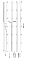
- FIG. 9 is a diagram showing an example in which the continuous casting start timing determination method according to the above embodiment is applied based on the temperature data of FIG.
- FIG. 9 shows the value obtained by dividing the number m of the temperature sensor 8 whose temperature exceeds the threshold value A by N, the status output by the withdrawal start determination unit 92, the withdrawal start instruction, and the time series change in the casting speed in actual operation. ing.
- the instruction to start pulling out the dummy bar could be issued at an appropriate timing, and no trouble occurred at the start of continuous casting.
Abstract
連続鋳造のスタートタイミングを精度良く判定することができる、連続鋳造のスタートタイミング判定方法、連続鋳造設備の操業方法、鋳片の製造方法、判定装置、連続鋳造スタート判定システム及び表示端末装置を提供すること。連続鋳造設備(1)において、ダミーバーの引き抜きタイミングである連続鋳造のスタートタイミングを判定する、連続鋳造のスタートタイミング判定方法であって、連続鋳造設備(1)の鋳型(5)の銅板における、所定の鋳込み方向位置である鋳込み方向判定位置に設けられた複数の温度センサ(8)を用いて、銅板の温度を測定する測定工程と、測定工程の測定結果と、連続鋳造設備(1)で鋳造される鋳片の幅とに基づいて推定される溶鋼(2)の湯面の鋳込み方向位置に応じて、スタートタイミングを判定する判定工程と、を備える、連続鋳造のスタートタイミング判定方法。
Description
本発明は、連続鋳造のスタートタイミング判定方法、連続鋳造設備の操業方法、鋳片の製造方法、判定装置、連続鋳造スタート判定システム及び表示端末装置に関する。
鋼の連続鋳造設備では、タンディッシュから連続的に注がれた溶鋼が、水冷管が埋設された鋳型により冷却された後、鋳型の下部から引き抜かれて、さらに冷却されることで鋳片が製造される。連続鋳造を開始する際は、鋳型の下側開口部にダミーバーを挿入し、ダミーバーヘッド部を底面として鋳型内部に溶鋼を注入し、溶鋼が所定のレベルに到達した後、ダミーバーを引き抜く手順により連続鋳造が開始される。
ダミーバーの引き抜き開始に際しては、鋳片の外側に凝固シェルが十分に形成され、適度に凝固していることが重要である。不十分な凝固状態で引き抜きが開始されると、凝固シェルが破れて漏鋼が発生する、いわゆるブレークアウトが起きる可能性がある。一方で、過剰に凝固した状態で引き抜きを開始すると、ダミーバー切り離しが困難となり、通常操業への遷移を阻害する要因となる。
これに対して、溶鋼の鋳型への注入開始から引き抜き開始に至るまでの自動化を目的とした連続鋳造のスタート方法が提案されている。例えば特許文献1には、鋳型内部での鋳片の凝固程度が溶鋼注入開始時点から引き抜き開始時点までの間の鋳型内部の溶鋼の滞留時間に依存することに着目し、渦流センサによって湯面レベルを計測し、溶鋼注入開始から予め設定された保持時間の経過後に引き抜き開始レベルに達したタイミングで引き抜きを開始する方法が記載されている。
しかしながら、特許文献1のように渦流センサにより湯面レベルを検知する手法では、連続鋳造設備の振動等によるノイズで検知精度が低下する場合がある。そのため、引き抜きを開始すべき湯面レベルに達していないにもかかわらず、鋳造を開始する場合や、引き抜きを開始すべき湯面レベルに達しているにもかかわらず鋳造を開始することができない場合がある。
そこで、本発明は、上記の課題に着目してなされたものであり、連続鋳造のスタートタイミングを精度良く判定することができる、連続鋳造のスタートタイミング判定方法、連続鋳造設備の操業方法、鋳片の製造方法、判定装置、連続鋳造スタート判定システム及び表示端末装置を提供することを目的としている。
そこで、本発明は、上記の課題に着目してなされたものであり、連続鋳造のスタートタイミングを精度良く判定することができる、連続鋳造のスタートタイミング判定方法、連続鋳造設備の操業方法、鋳片の製造方法、判定装置、連続鋳造スタート判定システム及び表示端末装置を提供することを目的としている。
(1)本発明の一態様によれば、連続鋳造設備において、ダミーバーの引き抜きタイミングである連続鋳造のスタートタイミングを判定する、連続鋳造のスタートタイミング判定方法であって、上記連続鋳造設備の鋳型の銅板における、所定の鋳込み方向位置である鋳込み方向判定位置に設けられた複数の温度センサを用いて、上記銅板の温度を測定する測定工程と、上記測定工程の測定結果と、上記連続鋳造設備で鋳造される鋳片の幅とに基づいて推定される溶鋼の湯面の上記鋳込み方向位置に応じて、上記スタートタイミングを判定する判定工程と、を備える、連続鋳造のスタートタイミング判定方法が提供される。
(2)上記(1)の連続鋳造のスタートタイミング判定方法において、上記判定工程では、上記鋳込み方向判定位置の上記複数の温度センサによって測定される温度のうち、一定割合以上の温度が閾値Aを超える場合に、上記湯面が上記鋳込み方向判定位置に到達したと判定し、上記鋳込み方向判定位置に到達した判定結果に応じて上記スタートタイミングを判定する。
(3)上記(2)の連続鋳造のスタートタイミング判定方法において、上記判定工程では、上記溶鋼が上記鋳込み方向判定位置に到達したと判定される状態が、所定の時間継続した場合に、上記スタートタイミングであることを判定する。
(4)上記(3)の連続鋳造のスタートタイミング判定方法において、上記判定工程では、上記溶鋼が上記鋳込み方向判定位置に到達したと判定される状態の継続時間が閾値C以上である場合に、上記スタートタイミングであると判断し、上記継続時間が閾値C未満である場合に、上記スタートタイミングではないと判断し、上記閾値Cは、湯面レベルの上昇速度によって分類されたテーブル値もしくは湯面レベルの上昇速度の関数に基づいて設定される。
(5)上記(1)~(4)のいずれか一つの連続鋳造のスタートタイミング判定方法において、上記判定工程では、上記鋳込み判定位置の上記複数の温度センサのうち、上記鋳片の幅の範囲内にある温度センサにより測定される温度のみを使用する。
(6)上記(1)~(5)のいずれか一つの連続鋳造のスタートタイミング判定方法において、上記判定工程では、上記鋳込み判定位置の上記複数の温度センサのうち、上記鋳片の長辺側の上記銅板に設けられた温度センサにより測定される温度のみを使用する。
(7)上記(1)~(6)のいずれか一つの連続鋳造のスタートタイミング判定方法において、上記測定工程では、上記鋳込み方向判定位置と異なる少なくとも一つの鋳込み方向位置に設けられた複数の温度センサをさらに用いて、上記銅板の温度を測定し、上記判定工程では、上記少なくとも一つの鋳込み方向位置における温度の測定結果と、上記鋳片の幅とに基づいて、上記少なくとも一つの鋳込み方向位置に上記溶鋼が到達したかを判定し、上記鋳込み方向判定位置と上記少なくとも一つの鋳込み方向位置とにおける、上記溶鋼が到達したか否かの判定結果を、表示する表示工程とをさらに備える。
(8)本発明の一態様によれば、上記(1)~(7)のいずれか一つの連続鋳造のスタートタイミング判定方法を用いて、上記スタートタイミングと判定されると、上記ダミーバーを引き抜き、上記連続鋳造を開始する、連続鋳造設備の操業方法が提供される。
(9)本発明の一態様によれば、連続鋳造設備を用いて鋳片を製造する際に、上記の連続鋳造設備の操業方法を用いる、鋳片の製造方法が提供される。
(10)本発明の一態様によれば、連続鋳造設備において、ダミーバーの引き抜きタイミングである連続鋳造のスタートタイミングを判定する、判定装置であって、上記連続鋳造設備の鋳型の銅板における、所定の鋳込み方向位置である鋳込み方向判定位置に設けられ、上記銅板の温度を測定する複数の温度センサと、上記複数の温度センサの測定結果と、上記連続鋳造設備で鋳造される鋳片の幅とに基づいて推定される溶鋼の湯面の上記鋳込み方向位置に応じて、上記スタートタイミングを判定する引き抜き開始判定部と、を備える、判定装置が提供される。
(11)本発明の一態様によれば、連続鋳造設備において、ダミーバーの引き抜きタイミングである連続鋳造のスタートタイミングを判定する、連続鋳造スタート判定システムであって、判定サーバー装置と、表示端末装置と、を備え、前記判定サーバー装置は、前記連続鋳造設備の鋳型の銅板における、所定の鋳込み方向位置である鋳込み方向判定位置を含む複数の鋳込み方向位置において、鋳型幅方向に複数設けられ、前記銅板の温度を測定する温度センサと、前記複数の温度センサの測定結果と、前記連続鋳造設備で鋳造される鋳片の幅とに基づいて推定される溶鋼の湯面の前記鋳込み方向位置に応じて、前記スタートタイミングを判定する引き抜き開始判定部と、前記引き抜き開始判定部で推定される溶鋼の湯面の前記鋳込み方向位置を含む湯面レベル状態を示す湯面レベル情報を出力する湯面レベル情報出力手段と、を有し、前記表示端末装置は、前記湯面レベル情報を取得する表示データ取得手段と、取得した前記湯面レベル情報に基づき、前記鋳込み方向位置の温度データに対応する位置ごとの湯面状態と、前記湯面状態を推定するための基準データとを表示する表示手段と、を有する、連続鋳造スタート判定システムが提供される。
(12)本発明の一態様によれば、連連続鋳造設備において、ダミーバーの引き抜きタイミングである連続鋳造のスタートタイミングを判定する判定サーバー装置とともに連続鋳造スタート判定システムを構成する表示端末装置であって、前記判定サーバー装置で推定される溶鋼の湯面の鋳込み方向位置を含む湯面レベル状態を示す湯面レベル情報を取得する表示データ取得手段と、取得した前記湯面レベル情報に基づき、鋳込み方向位置の温度データに対応する位置ごとの湯面状態と、前記湯面状態を推定するための基準データとを表示する表示手段と、を備え、前記溶鋼の湯面の鋳込み方向位置は、前記連続鋳造設備の鋳型の銅板における、所定の鋳込み方向位置である鋳込み方向判定位置を含む複数の鋳込み方向位置において、鋳型幅方向に複数設けられ、前記銅板の温度を測定する温度センサの測定結果と、前記連続鋳造設備で鋳造される鋳片の幅とに基づいて、前記サーバー装置で推定される、表示端末装置が提供される。
本発明の一態様によれば、連続鋳造のスタートタイミングを精度良く判定することができる、連続鋳造のスタートタイミング判定方法、連続鋳造設備の操業方法、鋳片の製造方法、判定装置、連続鋳造スタート判定システム及び表示端末装置が提供される。
以下の詳細な説明では、図面を参照して、本発明の実施形態を説明する。図面の記載において、同一又は類似の部分には同一又は類似の符号を付し、重複する説明を省略する。各図面は模式的なものであり、現実のものとは異なる場合が含まれる。また、以下に示す実施形態は、本発明の技術的思想を具体化するための装置や方法を例示するものであって、本発明の技術的思想は、構成部品の材質、構造、配置等を下記のものに特定するものでない。本発明の技術的思想は、特許請求の範囲に記載された請求項が規定する技術的範囲内において種々の変更を加えることができる。
本発明の一実施形態に係る連続鋳造のスタートタイミング判定方法について説明する。本実施形態では、溶鋼を連続鋳造する連続鋳造設備1における、連続鋳造のスタートタイミングを判定する。このような連続鋳造設備1では、後述するスタートタイミングでダミーバーを引き抜き、連続鋳造を開始することで、鋳片が製造される。
<連続鋳造設備の装置構成>
連続鋳造設備1は、図1に示すように、溶鋼2が注入されているタンディッシュ3と、タンディッシュ3から浸漬ノズル4を介して注がれた溶鋼2を冷却する銅製の鋳型5と、鋳型5から引き抜かれた半凝固状態の鋳片6を搬送する複数の鋳片支持ロール7と、鋳型5の長辺面及び短辺面に設置された複数の温度センサ8と、設置された温度センサ8の検出温度から連続鋳造のスタートタイミングを判定する判定装置9とを備える。また、鋳型5には、湯面を回転させる電磁撹拌磁場を発生させるコイル(不図示)が設置されている。
連続鋳造設備1は、図1に示すように、溶鋼2が注入されているタンディッシュ3と、タンディッシュ3から浸漬ノズル4を介して注がれた溶鋼2を冷却する銅製の鋳型5と、鋳型5から引き抜かれた半凝固状態の鋳片6を搬送する複数の鋳片支持ロール7と、鋳型5の長辺面及び短辺面に設置された複数の温度センサ8と、設置された温度センサ8の検出温度から連続鋳造のスタートタイミングを判定する判定装置9とを備える。また、鋳型5には、湯面を回転させる電磁撹拌磁場を発生させるコイル(不図示)が設置されている。
鋳型5は、図2に示すように、2枚の長辺面の銅板51に、2枚の短辺面の銅板52が挟まれて構成される。また、銅板51及び銅板52の内部には、複数の温度センサ8が設けられる。複数の温度センサ8は、鋳型5の鋳込み方向の複数の位置について、水平方向に並んで複数設けられる。つまり、図3に示すように銅板52を例にすると、銅板52の鋳込み方向(図3の上下方向)の位置である鋳込み方向位置に対して、複数の鋳込み方向位置に温度センサ8が設けられる。また、各鋳込み方向位置では、水平方向(図3の左右方向)に対して、複数の温度センサ8が設けられる。これは、銅板51についても同様であり、温度センサ8が設けられる鋳込み方向位置は、銅板51と銅板52とで同じ位置となる。さらに、鋳型5は、鋳造される鋳片6の幅(鋳片幅)を調整可能なように、短辺側の銅板52が図2の左右方向に移動可能に構成される。
温度センサ8は、鋳型5の温度を測定できるものであれば特に限定されないが、例えば、熱電対が用いられてもよく、光ファイバー方式のセンサが用いられてもよい。例えば、温度センサ8が光ファイバー方式のセンサである場合、銅板51,52の上端面から、銅板51,52の溶鋼側表面と平行に、鋳片の鋳造方向(つまり引き抜き方向)に光ファイバーを挿入する。このような方式は、連続鋳造設備1が垂直曲げ型スラブ連続鋳造機のように長辺側の銅板51が平坦な面で構成される場合に適用することが好ましい。また、温度センサ8の温度測定点の銅板51,52の厚み方向における設置位置は、設置した全ての温度測定点の銅板51,52の溶鋼側表面からの距離を同一として、且つ各温度測定点が銅板51,52の溶鋼側表面と冷却水スリット(銅板を冷却するための冷却水が通る水路)との間に位置するように設置する。
連続鋳造設備1は、さらに、図4に示すように、複数の温度センサ8の測定結果に基づいて、連続鋳造のスタートのタイミングを判定する判定装置9を有する。判定装置9は、コンピュータ等の情報処理装置によって構成され、CPU(Central Processing Unit)等の内部の演算処理装置がコンピュータプログラムを実行することにより、湯面レベル推定部91及び引き抜き開始判定部92として機能する。同じ鋳込み方向位置に設けられる温度センサ8の数は、特に限定されないが、測定精度の観点からは、後述するように、鋳造される鋳片幅において測定可能とされる温度センサ8の点数(個数)が10点以上であることが好ましい。
<スタートタイミング判定方法>
本実施形態では、図5に示す処理フローの判定処理に従って、連続鋳造のスタートタイミングが判定され、連続鋳造が開始される。なお、図5に示す判定処理は、判定装置9に対してスタートタイミング判定の実行指令が入力されたタイミングで開始となる。例えば、スタートタイミング判定の実行指令は、浸漬ノズル4からの鋳型5への溶鋼の2の注入開始のタイミングや作業者の操作によって入力される。
本実施形態では、図5に示す処理フローの判定処理に従って、連続鋳造のスタートタイミングが判定され、連続鋳造が開始される。なお、図5に示す判定処理は、判定装置9に対してスタートタイミング判定の実行指令が入力されたタイミングで開始となる。例えば、スタートタイミング判定の実行指令は、浸漬ノズル4からの鋳型5への溶鋼の2の注入開始のタイミングや作業者の操作によって入力される。
図5に示す連続鋳造のスタートタイミングの判定処理では、まず、ステップS100の処理として、引き抜き開始判定部92が、初期値としてステータス0及びタイマー0を出力する。ステータスは0,1又は2の3種類である。なお、ステータス2に達したタイミングでダミーバーの引き抜き開始の指示が出される。これにより、ステップS100の処理は完了し、判定処理はステップS102の処理に進む。
ステップS102の処理として、温度センサ8によって鋳型5の銅板51,52の温度が測定され、その後、湯面レベル推定部91は、測定される銅板51,52の温度及び鋳片幅のデータを取得する(測定工程)。これにより、ステップS102の処理は完了し、判定処理はステップS104の処理に進む。
ステップS102の処理として、温度センサ8によって鋳型5の銅板51,52の温度が測定され、その後、湯面レベル推定部91は、測定される銅板51,52の温度及び鋳片幅のデータを取得する(測定工程)。これにより、ステップS102の処理は完了し、判定処理はステップS104の処理に進む。
ステップS104の処理として、湯面レベル推定部91は、ステップS102の処理において取得した鋳片幅のデータと、予め用意した温度センサの設置座標データとを用いて、複数の温度センサ8のうち、鋳片幅の範囲内にある温度センサの点数Nをカウントする。鋳型5は、図2に示すように、2枚の長辺面の銅板51に、2枚の短辺面の銅板52が挟まれており、鋳片幅が狭い場合は長辺面の銅板51の端部に設置された温度センサ8は短辺面の銅板52より外側に位置する。このため、銅板52より外側に位置する銅板51の温度センサ8は、鋳造中でも温度が低位となる。したがって、このような温度センサ8では、湯面が温度センサ8のあるレベルに達しているか判別することは困難であり、本判定には用いるべきではないので、ステップS104ではこのような温度センサ8を予め除外する。これにより、ステップS104の処理は完了し、判定処理はステップS106の処理に進む。
ステップS106の処理では、湯面レベル推定部10が、ステップS104の処理において抽出された温度センサ8のうち、所定の鋳込み方向位置にある複数の温度センサ8について、温度が閾値Aを超えたセンサの点数mをカウントする。鋳込み方向位置は、銅板51,52の上端からの鋳込み方向への距離であるが、銅板51,52の上端からの鉛直方向への距離であってもよい。所定の鋳込み方向位置は、連続鋳造が開始される際に鋳型5の湯面高さとして適当な鋳込み方向位置であり、例えば、連続鋳造の定常状態における湯面高さ(メニスカス位置)或いはその近傍の鋳込み方向位置である。なお、この所定の鋳込み方向位置を、鋳込み方向判定位置ともいう。例えば、図3に示す例では、銅板の上端から温度センサ8の4断目の位置を、鋳込み方向位置(方形の破線で示す領域)とする。使用する温度センサ8に関して、銅板上端からの高さ位置(鋳込み方向位置)は適宜の数だけ設定可能であるが、同じ鋳込み方向位置にある温度センサ8のうち鋳片幅の範囲内にある点数Nは10点以上であることが好ましい。これにより、ステップS106の処理は完了し、判定処理はステップS108の処理に進む。閾値Aは、銅板51,52の温度センサ8が設置された鋳込み方向位置に溶鋼2が到達したことを検出可能な値として設定されるものであり、銅板表面からの温度センサ8の距離や銅板51,52の材質等によって適宜設定される。
ステップS108の処理では、湯面レベル推定部91が、鋳込み方向判定位置にある複数の温度センサ8について、温度が閾値Aを超えた温度センサ8が一定割合以上であるか判定する。すなわち、温度が閾値Aを超えたセンサの点数mを、鋳片幅の範囲内にある点数Nで除算した値が閾値B以上であるかを判定する。この判定では、鋳込み方向判定位置において、測定される温度が一定割合以上であるか否かが判定されることで、鋳込み方向判定位置に溶鋼2の湯面が到達したか否かが判定される。ステップS108の判定において、閾値Bを下回った場合は、判定処理はステップS110の処理に進み、閾値B以上であった場合は、判定処理はステップS112の処理に進む。閾値Bは、鋳込み方向判定位置において溶鋼2が到達したと判断できる値として設定されることが好ましく、温度センサ8の検出精度等に応じて設定される。引き抜き開始前の湯面は、幅方向及び厚み方向ともにばらつきが大きい場合がある。したがって、閾値Bが1に限りなく近い場合、鋳込み方向判定位置に湯面が到達したと判定するタイミングが遅れてしまい、引き抜き開始が遅れて生産性を低下させるか、溶鋼が鋳型からあふれる恐れがある。一方で、閾値Bが過小である場合は、平均的な湯面レベル(鋳型5内における湯面の鋳込み方向位置又は高さ方向位置)が鋳込み方向判定位置に達していないにもかかわらず湯面が到達したと誤判定するリスクが高まる。したがって、閾値Bは、0.5以上0.9以下の値に設定されることが好ましい。
ステップS110の処理では、引き抜き開始判定部92が、ステータス0及びタイマー0を出力し、判定処理はステップS102の処理に戻る。
一方、ステップS112の処理では、引き抜き開始判定部92が、ステータス1を出力し、判定処理はステップS114の処理に進む。
一方、ステップS112の処理では、引き抜き開始判定部92が、ステータス1を出力し、判定処理はステップS114の処理に進む。
ステップS114の処理では、引き抜き開始判定部92が、タイマーが閾値C以上であるか判定する。つまり、ステップS114では、鋳込み方向判定位置に湯面が到達したと判定される状態が所定の時間継続したか否かが判定される。なお、タイマーの値は、鋳込み判定位置に湯面が到達したと判定される状態の継続時間を示すものである。閾値Cを下回った場合は、スタートタイミングではないと判断されて、判定処理はステップS116に進む。一方、閾値C以上であった場合は、スタートタイミングであると判定されて、判定処理はステップS118の処理に進む。閾値Cは、鋳込み方向判定位置に到達した溶鋼2に、引き抜きに耐えうる程度に凝固シェルが十分に形成されたと判断できる値として設定されることが好ましい。閾値Cは、鋳型5の冷却能や過去の実績データ等から適宜設定されてもよい。例えば、タンディッシュ3と浸漬ノズル4との間にあるスライディングノズルの開度と、鋳片の幅及び厚みとから、平均的な湯面レベルの上昇速度を推定することができる。閾値Cが過大である場合、溶鋼が鋳型から溢れる恐れがある。一方で、閾値Cが過小である場合、未凝固のまま、つまり凝固シェルが十分に形成されていない状態で、引き抜きを開始してしまう可能性がある。したがって、閾値Cは、湯面レベルの上昇速度によって分類されたテーブル値もしくは湯面レベルの上昇速度の関数に基づいて、5秒以上15秒以下の間で設定されることが好ましい。
ステップS116の処理では、引き抜き開始判定部92が、タイマーを1秒カウントアップした値を出力し、判定処理はステップS102の処理に戻る。なお、本実施形態では、ステップS102の測定工程における温度センサ8による温度測定は、1秒間隔で連続して行われ、ステップS102~S116までの一連の処理も1秒間隔で行われる。
ステップS118の処理では、引き抜き開始判定部92が、ステータス2を出力し、判定処理はステップS120の処理に進む。
ステップS120の処理では、引き抜き開始判定部92が、ダミーバー引き抜き開始指示を出し、一連の判定処理を終了する。なお、ステップS104~S114における判定処理を、判定工程ともいう。つまり、本実施形態では、ステップS102の測定工程の後、ステップS104~S114の判定工程が行われる。図5に示す処理フローが終了すると、連続鋳造が開始され、連続鋳造設備1で鋳片6が製造されることとなる。
ステップS118の処理では、引き抜き開始判定部92が、ステータス2を出力し、判定処理はステップS120の処理に進む。
ステップS120の処理では、引き抜き開始判定部92が、ダミーバー引き抜き開始指示を出し、一連の判定処理を終了する。なお、ステップS104~S114における判定処理を、判定工程ともいう。つまり、本実施形態では、ステップS102の測定工程の後、ステップS104~S114の判定工程が行われる。図5に示す処理フローが終了すると、連続鋳造が開始され、連続鋳造設備1で鋳片6が製造されることとなる。
本実施形態に係るスタートタイミング判定方法は、湯面の鋳込み方向位置に応じてスタートタイミングを判定するものであり、鋳片幅の範囲内にある温度センサ8の測定結果から、閾値B及び閾値Cを用いて判定をすることで、鋳込み方向判定位置に湯面が到達し、十分に時間が経過したかを精度良く判定することができる。また、渦流センサを用いて湯面を検出する場合に比べ、鋳型5に設けた温度センサ8を用いて湯面を検出するため、連続鋳造設備の振動等の影響を受けないため、より高い精度で湯面を検出することができる。また、連続鋳造の開始時に溶鋼2を鋳型5に注入する際には、注入された溶鋼2が鋳型5内で飛散することで湯面高さよりも高い鋳込み方向位置においても温度センサ8により測定される温度が高くなる場合がある。しかし、本実施形態に係るスタートタイミング判定方法によれば、閾値B及び閾値Cを用いて判定することにより、このような場合においても湯面が所定の鋳込み方向位置に到達したかを精度良く判定することができる。このため、連続鋳造のスタートタイミングを精度良く判定することができる。
また、本実施形態に係るスタートタイミング判定方法は、水平方向に並んだ複数の温度センサ8の測定結果を用いる。これにより、幅方向や厚み方向への溶鋼の大きな湯面変動を考慮することができる。一方、温度センサを鋳造方向に一次元配置するような場合、幅方向や厚み方向への溶鋼の大きな湯面変動があると湯面を正確に検知することができず、スタートタイミングを精度よく判定することができない。
<変形例>
以上で、特定の実施形態を参照して本発明を説明したが、これら説明によって発明を限定することを意図するものではない。本発明の説明を参照することにより、当業者には、開示された実施形態とともに種々の変形例を含む本発明の別の実施形態も明らかである。従って、特許請求の範囲に記載された発明の実施形態には、本明細書に記載したこれらの変形例を単独または組み合わせて含む実施形態も網羅すると解すべきである。
以上で、特定の実施形態を参照して本発明を説明したが、これら説明によって発明を限定することを意図するものではない。本発明の説明を参照することにより、当業者には、開示された実施形態とともに種々の変形例を含む本発明の別の実施形態も明らかである。従って、特許請求の範囲に記載された発明の実施形態には、本明細書に記載したこれらの変形例を単独または組み合わせて含む実施形態も網羅すると解すべきである。
例えば、上記実施形態では、所定の鋳込み方向位置である鋳込み方向判定位置の温度センサ8の測定結果を用いてスタートタイミングの判定をするとしたが、本発明はかかる例に限定されない。本発明では、複数の鋳込み方向位置の温度センサ8の温度の測定結果、つまり鋳込み方向判定位置での測定結果と、鋳込み方向判定位置とは異なる少なくとも一つの鋳込み方向位置での測定結果とを用いてスタートタイミングの判定をしてもよい。例えば、上記実施形態における鋳込み方向判定と、それよりも鋳込み方向の下流側(図3における下側)の温度センサ8についても、鋳込み方向位置毎に、上記実施形態と同様にステップS100~S118の処理を行い、ステータスを算出するようにしてもよい。そして、鋳込み方向判定位置を含む複数の鋳込み方向位置のステータスが2となった場合に、引き抜き開始指示を出すようにしてもよい。また、鋳込み方向判定位置と、鋳込み方向判定位置の上流側及び下流側の少なくとも2箇所の鋳込み方向位置との温度センサ8について、鋳込み方向位置毎にステータスを算出するようにしてもよい。この場合、例えば、鋳込み方向判定位置でのステータスが2となっていなくても、上流側及び下流側の鋳込み方向位置でのステータスが2となっている場合には、鋳込み方向判定位置での測定において異常が発生している可能性がある。このため、このような場合において、上流側及び下流側の鋳込み方向位置でのステータスから、鋳込み判定位置でのステータスも2であるとして、引き抜き開始指示を出すようにしてもよい。
また、複数の鋳込み方向位置においてステータスを算出する場合、鋳込み方向位置毎のステータスの算出結果を表示させるようにしてもよい。図6には、鋳込み方向位置毎のステータスの算出結果を表示させる一例を示す。図6に示す例では、鋳込み方向位置毎のステータスの算出結果を縦に並んだ方形のブロックで示し、ブロックの表示をステータスに応じて変えることで算出結果を表示させる。なお、図6に示す下側が鋳造方向の下流側となり、上側が鋳造方向の上流側となる。図6に示す例では、鋳込み方向位置に22段の温度センサ8を設置し、5段目と6段目との間がメニスカス位置となり、6段目がメニスカス位置の直下の鋳込み方向位置が鋳込み方向判定位置となる。そして、溶鋼2の鋳型5への注入が正常に行われると、ダミーバーよりも上側のブロック(図6の16段目)の下側からステータスが変わっていき、鋳造開始のタイミングになると、溶鋼が注入される範囲内で鋳込み方向判定位置から下側のステータスが全て2となる。このような表示をすることにより、溶鋼の湯面が鋳型5内のどの鋳込み方向位置まで到達したかが分かるようになり、作業者は、鋳型5内の溶鋼の湯面位置を視覚的に認識できるようになる。これにより、作業者は、スタートタイミングを正確に判定することができるようになる。なお、溶鋼が鋳型5内のどの鋳込み方向位置まで到達したかを示す情報(溶鋼の湯面の鋳込み方向位置)を含む湯面レベル状態を示す情報を湯面レベル情報ともいう。また、図6に示すように、ステータス0,1,2の表示以外にも、測定された温度が異常と判定される場合にステータスとして表示する異常フラグを表示してもよい。さらに、温度異常の閾値(上下限)、湯面判定温度加減(閾値A)、ステータス遷移時間(閾値C)、湯面判定割合(閾値B)及び湯面判定用段数(鋳込み方向判定位置)を表示させるようにしてもよい。
さらに、鋳片幅の範囲内にある温度センサ8について、同じ鋳込み方向位置の他の温度センサ8が温度上昇しているのに関わらず温度上昇がみられない(測温不良となる)場合には、測温不良となる温度センサ8をNに含めない又は閾値Bを調整するようにしてもよい。
さらに、上記実施形態では、温度センサ8が複数の鋳込み方向位置に設けられるとしたが、本発明はかかる例に限定されない。上記実施形態と同様に、所定の鋳込み方向位置である鋳込み方向判定位置でのみ連続鋳造のスタートタイミングを判定する場合には、鋳込み方向判定位置にのみ温度センサ8が設けられるようにしてもよい。
さらに、上記実施形態では、温度センサ8が複数の鋳込み方向位置に設けられるとしたが、本発明はかかる例に限定されない。上記実施形態と同様に、所定の鋳込み方向位置である鋳込み方向判定位置でのみ連続鋳造のスタートタイミングを判定する場合には、鋳込み方向判定位置にのみ温度センサ8が設けられるようにしてもよい。
さらに、上記実施形態では、長辺側の銅板51に設けられた温度センサ8と短辺側の銅板52に設けられた温度センサ8との両方の温度センサ8の測定結果を用いるとしたが、本発明はかかる例に限定されない。鋳片6の引き抜きを開始する際には、長辺側の鋳片6の凝固シェルの厚みが問題となる場合が多い。このため、長辺側の銅板51に設けられた温度センサ8の測定結果のみを用いて、スタートタイミングの判定をするようにしてもよい。この場合、長辺側の銅板51にのみ温度センサ8を設けるようにしてもよい。
さらに、上記実施形態では、判定装置9は、図4に示す装置構成であるとしたが、この装置構成に温度センサ8を加えて判定装置9としてもよい。つまり、本発明では、連続鋳造のスタートタイミングを判定する判定装置9は、湯面レベル推定部91と、引き抜き開始判定部92と、複数の温度センサ8とを備えてもよい。
さらに、上記実施形態では、温度センサ8の測温値そのものを用いることとしたが、本発明はかかる例に限定されない。例えば、2次元配置された温度センサ8の測温値を線形内挿や3次スプライン内挿等の内挿法を用いて、鋳型の銅板の温度分布を推定することで、鋳込み方向判定位置は温度センサ8の存在しない位置に設定してもよい。
さらに、上記実施形態では、温度センサ8の測温値そのものを用いることとしたが、本発明はかかる例に限定されない。例えば、2次元配置された温度センサ8の測温値を線形内挿や3次スプライン内挿等の内挿法を用いて、鋳型の銅板の温度分布を推定することで、鋳込み方向判定位置は温度センサ8の存在しない位置に設定してもよい。
さらに、本発明は、連続鋳造スタート判定システムにも適用することができる。この場合、例えば、図7に示すように、連続鋳造スタート判定システム10は、判定サーバー装置11と表示端末装置12とを備える。判定サーバー装置11と表示端末装置12とは、ネットワークを介して無線又は有線で接続される。判定サーバー装置11は、温度センサ8と、湯面レベル推定部91と、引き抜き開始判定部92と、表示データ出力部13とを有する。温度センサ8、湯面レベル推定部91及び引き抜き開始判定部92は、上記実施形態や他の変形例と同様である。つまり、温度センサ8は、連続鋳造設備1の鋳型5の銅板における、所定の鋳込み方向位置である鋳込み方向判定位置を含む複数の鋳込み方向位置において、鋳型幅方向に複数設けられ、銅板の温度を測定する。また、湯面レベル推定部91は、複数の温度センサ8の測定結果と、連続鋳造設備1で鋳造される鋳片6の幅とに基づいて、溶鋼の湯面の鋳込み方向位置を推定する。さらに、引き抜き開始判定部92は、推定される溶鋼の湯面の鋳込み方向位置に応じて、スタートタイミングを判定する。表示データ出力部13は、推定される溶鋼の湯面の鋳込み方向位置を含む湯面レベル状態を示す湯面レベル情報を表示端末装置12へ出力する。また、表示端末装置12は、表示データ取得手段14と表示手段15とを有する。表示データ取得手段14は、判定サーバー装置11から湯面レベル情報を取得する。表示手段15は、取得した湯面レベル情報に基づき、鋳込み方向位置の温度データに対応する位置ごとの湯面状態と、湯面状態を推定するための基準データとを表示する。基準データは、ステップS108やS114で用いる閾値BやC等である。例えば、表示手段15は、画像として図6に示す情報を表示するモニタ等の表示装置である。また、表示手段15は、図6に示す情報に加えて、後述する図8及び図9のように、鋳造条件や基準データ、銅版の温度等の時系列データを合わせて表示してもよい。
本発明者らは、実施例として、実際の連続鋳造設備1において上記実施形態に係るスタートタイミング判定方法を用いて連続鋳造を開始した。実施例では、メニスカス位置の直下を鋳込み方向判定位置として温度センサ8を設置した。鋳込み方向判定位置には、38個の温度センサ8を設けた。連続鋳造を行う際の、鋳片幅の範囲内にある温度センサ8の点数は、30点であった。
図8に、溶鋼2を鋳型5に注入する前後における、温度センサ8の測定結果を示す。図8に示すように、長破線で示すタイミングで溶鋼注入を開始したところ、ばらつきがみられたものの、ほぼ全ての温度センサ8の検出温度が上昇した。本実施例では、図の点線で示される値を閾値A=50℃として、上記実施形態に係る連続鋳造のスタートタイミング判定方法を適用した。
図9は、図8の温度データに基づいて上記実施形態に係る連続鋳造のスタートタイミング判定方法を適用した例を示す図である。図9は、温度が閾値Aを超えた温度センサ8の点数mをNで割った値、引き抜き開始判定部92が出力したステータス、引き抜き開始指示、及び実操業における鋳造速度の時系列変化を示している。本実施例では、m/Nの閾値B=0.6、ステータス1からステータス2に遷移するタイマーの閾値C=10秒とした。
本実施例では、ダミーバーの引き抜き開始指示を適切なタイミングで出すことができ、連続鋳造スタート時においてトラブルが発生することがなかった。
本実施例では、ダミーバーの引き抜き開始指示を適切なタイミングで出すことができ、連続鋳造スタート時においてトラブルが発生することがなかった。
1 連続鋳造設備
2 溶鋼
3 タンディッシュ
4 浸漬ノズル
5 鋳型
51,52 銅板
6 鋳片
7 鋳片支持ロール
8 温度センサ
9 判定装置
91 湯面レベル推定部
92 引き抜き開始判定部
10 連続鋳造スタート判定システム
11 判定サーバー装置
12 表示端末装置
13 表示データ出力部
14 表示データ取得手段
15 表示手段
2 溶鋼
3 タンディッシュ
4 浸漬ノズル
5 鋳型
51,52 銅板
6 鋳片
7 鋳片支持ロール
8 温度センサ
9 判定装置
91 湯面レベル推定部
92 引き抜き開始判定部
10 連続鋳造スタート判定システム
11 判定サーバー装置
12 表示端末装置
13 表示データ出力部
14 表示データ取得手段
15 表示手段
Claims (12)
- 連続鋳造設備において、ダミーバーの引き抜きタイミングである連続鋳造のスタートタイミングを判定する、連続鋳造のスタートタイミング判定方法であって、
前記連続鋳造設備の鋳型の銅板における、所定の鋳込み方向位置である鋳込み方向判定位置に設けられた複数の温度センサを用いて、前記銅板の温度を測定する測定工程と、
前記測定工程の測定結果と、前記連続鋳造設備で鋳造される鋳片の幅とに基づいて推定される溶鋼の湯面の前記鋳込み方向位置に応じて、前記スタートタイミングを判定する判定工程と、
を備える、連続鋳造のスタートタイミング判定方法。 - 前記判定工程では、
前記鋳込み方向判定位置の前記複数の温度センサによって測定される温度のうち、一定割合以上の温度が閾値Aを超える場合に、前記湯面が前記鋳込み方向判定位置に到達したと判定し、
前記鋳込み方向判定位置に到達した判定結果に応じて前記スタートタイミングを判定する、請求項1に記載の連続鋳造のスタートタイミング判定方法。 - 前記判定工程では、前記溶鋼が前記鋳込み方向判定位置に到達したと判定される状態が、所定の時間継続した場合に、前記スタートタイミングであることを判定する、請求項2に記載の連続鋳造のスタートタイミング判定方法。
- 前記判定工程では、前記溶鋼が前記鋳込み方向判定位置に到達したと判定される状態の継続時間が閾値C以上である場合に、前記スタートタイミングであると判断し、前記継続時間が閾値C未満である場合に、前記スタートタイミングではないと判断し、
前記閾値Cは、湯面レベルの上昇速度によって分類されたテーブル値もしくは湯面レベルの上昇速度の関数に基づいて設定される、請求項3に記載の連続鋳造のスタートタイミング判定方法。 - 前記判定工程では、前記鋳込み判定位置の前記複数の温度センサのうち、前記鋳片の幅の範囲内にある温度センサにより測定される温度のみを使用する、請求項1~4のいずれか1項に記載の連続鋳造のスタートタイミング判定方法。
- 前記判定工程では、前記鋳込み判定位置の前記複数の温度センサのうち、前記鋳片の長辺側の前記銅板に設けられた温度センサにより測定される温度のみを使用する、請求項1~5のいずれか1項に記載の連続鋳造のスタートタイミング判定方法。
- 前記測定工程では、前記鋳込み方向判定位置と異なる少なくとも一つの鋳込み方向位置に設けられた複数の温度センサをさらに用いて、前記銅板の温度を測定し、
前記判定工程では、前記少なくとも一つの鋳込み方向位置における温度の測定結果と、前記鋳片の幅とに基づいて、前記少なくとも一つの鋳込み方向位置に前記溶鋼が到達したかを判定し、
前記鋳込み方向判定位置と前記少なくとも一つの鋳込み方向位置とにおける、前記溶鋼が到達したか否かの判定結果を、表示する表示工程とをさらに備える、請求項1~6のいずれか1項に記載の連続鋳造のスタートタイミング判定方法。 - 請求項1~7のいずれか一つの連続鋳造のスタートタイミング判定方法を用いて、前記スタートタイミングと判定されると、前記ダミーバーを引き抜き、前記連続鋳造を開始する、連続鋳造設備の操業方法。
- 連続鋳造設備を用いて鋳片を製造する際に、請求項8に記載の連続鋳造設備の操業方法を用いる、鋳片の製造方法。
- 連続鋳造設備において、ダミーバーの引き抜きタイミングである連続鋳造のスタートタイミングを判定する、判定装置であって、
前記連続鋳造設備の鋳型の銅板における、所定の鋳込み方向位置である鋳込み方向判定位置に設けられ、前記銅板の温度を測定する複数の温度センサと、
前記複数の温度センサの測定結果と、前記連続鋳造設備で鋳造される鋳片の幅とに基づいて推定される溶鋼の湯面の前記鋳込み方向位置に応じて、前記スタートタイミングを判定する引き抜き開始判定部と、
を備える、判定装置。 - 連続鋳造設備において、ダミーバーの引き抜きタイミングである連続鋳造のスタートタイミングを判定する、連続鋳造スタート判定システムであって、
判定サーバー装置と、
表示端末装置と、
を備え、
前記判定サーバー装置は、
前記連続鋳造設備の鋳型の銅板における、所定の鋳込み方向位置である鋳込み方向判定位置を含む複数の鋳込み方向位置において、鋳型幅方向に複数設けられ、前記銅板の温度を測定する温度センサと、
前記複数の温度センサの測定結果と、前記連続鋳造設備で鋳造される鋳片の幅とに基づいて推定される溶鋼の湯面の前記鋳込み方向位置に応じて、前記スタートタイミングを判定する引き抜き開始判定部と、
前記引き抜き開始判定部で推定される溶鋼の湯面の前記鋳込み方向位置を含む湯面レベル状態を示す湯面レベル情報を出力する湯面レベル情報出力手段と、を有し、
前記表示端末装置は、
前記湯面レベル情報を取得する表示データ取得手段と、
取得した前記湯面レベル情報に基づき、前記鋳込み方向位置の温度データに対応する位置ごとの湯面状態と、前記湯面状態を推定するための基準データとを表示する表示手段と、を有する、連続鋳造スタート判定システム。 - 連続鋳造設備において、ダミーバーの引き抜きタイミングである連続鋳造のスタートタイミングを判定する判定サーバー装置とともに連続鋳造スタート判定システムを構成する表示端末装置であって、
前記判定サーバー装置で推定される溶鋼の湯面の鋳込み方向位置を含む湯面レベル状態を示す湯面レベル情報を取得する表示データ取得手段と、
取得した前記湯面レベル情報に基づき、鋳込み方向位置の温度データに対応する位置ごとの湯面状態と、前記湯面状態を推定するための基準データとを表示する表示手段と、
を備え、
前記溶鋼の湯面の鋳込み方向位置は、前記連続鋳造設備の鋳型の銅板における、所定の鋳込み方向位置である鋳込み方向判定位置を含む複数の鋳込み方向位置において、鋳型幅方向に複数設けられ、前記銅板の温度を測定する温度センサの測定結果と、前記連続鋳造設備で鋳造される鋳片の幅とに基づいて、前記サーバー装置で推定される、表示端末装置。
Priority Applications (1)
| Application Number | Priority Date | Filing Date | Title |
|---|---|---|---|
| JP2023529885A JP7384323B1 (ja) | 2022-01-27 | 2023-01-25 | 連続鋳造のスタートタイミング判定方法、連続鋳造設備の操業方法、鋳片の製造方法、判定装置、連続鋳造スタート判定システム及び表示端末装置 |
Applications Claiming Priority (2)
| Application Number | Priority Date | Filing Date | Title |
|---|---|---|---|
| JP2022011171 | 2022-01-27 | ||
| JP2022-011171 | 2022-01-27 |
Publications (1)
| Publication Number | Publication Date |
|---|---|
| WO2023145786A1 true WO2023145786A1 (ja) | 2023-08-03 |
Family
ID=87471503
Family Applications (1)
| Application Number | Title | Priority Date | Filing Date |
|---|---|---|---|
| PCT/JP2023/002318 WO2023145786A1 (ja) | 2022-01-27 | 2023-01-25 | 連続鋳造のスタートタイミング判定方法、連続鋳造設備の操業方法、鋳片の製造方法、判定装置、連続鋳造スタート判定システム及び表示端末装置 |
Country Status (2)
| Country | Link |
|---|---|
| JP (1) | JP7384323B1 (ja) |
| WO (1) | WO2023145786A1 (ja) |
Citations (4)
| Publication number | Priority date | Publication date | Assignee | Title |
|---|---|---|---|---|
| JPH1190589A (ja) * | 1997-09-16 | 1999-04-06 | Nippon Steel Corp | 連続鋳造のオートスタート方法 |
| JPH11123516A (ja) * | 1997-10-17 | 1999-05-11 | Sumitomo Metal Ind Ltd | 連続鋳造設備の操業方法 |
| JP2004276050A (ja) * | 2003-03-13 | 2004-10-07 | Sumitomo Metal Ind Ltd | 連続鋳造のスタート方法 |
| JP2012170999A (ja) * | 2011-02-23 | 2012-09-10 | Jfe Steel Corp | モールド内溶鋼湯面レベル制御方法 |
-
2023
- 2023-01-25 WO PCT/JP2023/002318 patent/WO2023145786A1/ja active Application Filing
- 2023-01-25 JP JP2023529885A patent/JP7384323B1/ja active Active
Patent Citations (4)
| Publication number | Priority date | Publication date | Assignee | Title |
|---|---|---|---|---|
| JPH1190589A (ja) * | 1997-09-16 | 1999-04-06 | Nippon Steel Corp | 連続鋳造のオートスタート方法 |
| JPH11123516A (ja) * | 1997-10-17 | 1999-05-11 | Sumitomo Metal Ind Ltd | 連続鋳造設備の操業方法 |
| JP2004276050A (ja) * | 2003-03-13 | 2004-10-07 | Sumitomo Metal Ind Ltd | 連続鋳造のスタート方法 |
| JP2012170999A (ja) * | 2011-02-23 | 2012-09-10 | Jfe Steel Corp | モールド内溶鋼湯面レベル制御方法 |
Also Published As
| Publication number | Publication date |
|---|---|
| JPWO2023145786A1 (ja) | 2023-08-03 |
| JP7384323B1 (ja) | 2023-11-21 |
Similar Documents
| Publication | Publication Date | Title |
|---|---|---|
| KR101443278B1 (ko) | 벌징 감지 모듈 및 이를 이용한 벌징 감지 방법 | |
| JP5673100B2 (ja) | ブレイクアウト予知方法 | |
| JP6950860B1 (ja) | ブレークアウト予知方法、連続鋳造機の操業方法、及び、ブレークアウト予知装置 | |
| JP4105839B2 (ja) | 連続鋳造における鋳型内鋳造異常検出方法 | |
| JP5092631B2 (ja) | 連続鋳造におけるブレークアウト検出方法及び装置、該装置を用いた鋼の連続鋳造方法、ブレークアウト防止装置 | |
| WO2023145786A1 (ja) | 連続鋳造のスタートタイミング判定方法、連続鋳造設備の操業方法、鋳片の製造方法、判定装置、連続鋳造スタート判定システム及び表示端末装置 | |
| JP4112783B2 (ja) | 連続鋳造設備におけるブレークアウト検出方法 | |
| JP5884177B2 (ja) | 連続鋳造鋳片の凝固完了位置推定方法及び凝固完了位置推定装置 | |
| JP6435988B2 (ja) | 連続鋳造におけるブレークアウト予知方法、ブレークアウト防止方法、凝固シェル厚の測定方法、ブレークアウト予知装置およびブレークアウト防止装置 | |
| JPH01210160A (ja) | 連続鋳造における縦割れ予知方法 | |
| JP5707844B2 (ja) | 連続鋳造におけるブレークアウト検出方法及び装置 | |
| JP3103498B2 (ja) | 連続鋳造におけるブレイクアウトの予知および防止方法 | |
| JP6347236B2 (ja) | ブレークアウト予知方法、ブレークアウト予知装置および連続鋳造方法 | |
| JP5412872B2 (ja) | 連続鋳造におけるブレークアウト検出方法及び装置、該装置を用いた鋼の連続鋳造方法、ブレークアウト防止装置 | |
| JPH01143748A (ja) | 連続鋳造方法 | |
| JP5593801B2 (ja) | 連続鋳造のブレークアウト予知方法 | |
| WO2024070088A1 (ja) | 鋳型、制御設備及び鋼の連続鋳造方法 | |
| WO2021256063A1 (ja) | ブレークアウト予知方法、連続鋳造機の操業方法、及び、ブレークアウト予知装置 | |
| JP7135728B2 (ja) | 鋳片品質推定方法、鋼材の製造方法、鋳片品質推定装置、およびプログラム | |
| JP4214818B2 (ja) | 拘束性ブレークアウト予知用温度センサの異常検知方法 | |
| JP3093586B2 (ja) | 連続鋳造鋳片の縦割れ検知方法 | |
| JP2022190572A (ja) | 連続鋳造における鋳片欠陥検知方法 | |
| JP2017024047A (ja) | 拘束性ブレークアウトの予知方法及び予知装置 | |
| JPWO2023145786A5 (ja) | ||
| JP3062723B2 (ja) | 鋳型内の凝固収縮による鋳片表面凹み形状の測定方法 |
Legal Events
| Date | Code | Title | Description |
|---|---|---|---|
| WWE | Wipo information: entry into national phase |
Ref document number: 2023529885 Country of ref document: JP |
|
| 121 | Ep: the epo has been informed by wipo that ep was designated in this application |
Ref document number: 23746996 Country of ref document: EP Kind code of ref document: A1 |