WO2023145786A1 - Procédé de détermination de temporisation de démarrage de coulée continue, procédé de fonctionnement d'installation de coulée continue, procédé de fabrication de brame, dispositif de détermination, système de détermination de démarrage de coulée continue, et équipement terminal d'affichage - Google Patents
Procédé de détermination de temporisation de démarrage de coulée continue, procédé de fonctionnement d'installation de coulée continue, procédé de fabrication de brame, dispositif de détermination, système de détermination de démarrage de coulée continue, et équipement terminal d'affichage Download PDFInfo
- Publication number
- WO2023145786A1 WO2023145786A1 PCT/JP2023/002318 JP2023002318W WO2023145786A1 WO 2023145786 A1 WO2023145786 A1 WO 2023145786A1 JP 2023002318 W JP2023002318 W JP 2023002318W WO 2023145786 A1 WO2023145786 A1 WO 2023145786A1
- Authority
- WO
- WIPO (PCT)
- Prior art keywords
- continuous casting
- determination
- casting
- start timing
- molten steel
- Prior art date
Links
- 238000009749 continuous casting Methods 0.000 title claims abstract description 126
- 238000000034 method Methods 0.000 title claims abstract description 96
- 238000004519 manufacturing process Methods 0.000 title claims abstract description 6
- 238000005266 casting Methods 0.000 claims abstract description 144
- 229910000831 Steel Inorganic materials 0.000 claims abstract description 78
- 239000010959 steel Substances 0.000 claims abstract description 78
- RYGMFSIKBFXOCR-UHFFFAOYSA-N Copper Chemical compound [Cu] RYGMFSIKBFXOCR-UHFFFAOYSA-N 0.000 claims abstract description 61
- 229910052802 copper Inorganic materials 0.000 claims abstract description 61
- 239000010949 copper Substances 0.000 claims abstract description 61
- 238000005259 measurement Methods 0.000 claims abstract description 27
- 239000002184 metal Substances 0.000 claims abstract description 26
- 229910052751 metal Inorganic materials 0.000 claims abstract description 26
- 239000000155 melt Substances 0.000 claims description 15
- XLYOFNOQVPJJNP-UHFFFAOYSA-N water Substances O XLYOFNOQVPJJNP-UHFFFAOYSA-N 0.000 claims description 10
- 230000008569 process Effects 0.000 description 45
- 238000009529 body temperature measurement Methods 0.000 description 7
- 238000010586 diagram Methods 0.000 description 7
- 238000012545 processing Methods 0.000 description 6
- 238000004364 calculation method Methods 0.000 description 4
- 238000001816 cooling Methods 0.000 description 4
- 230000004048 modification Effects 0.000 description 4
- 238000012986 modification Methods 0.000 description 4
- 238000011144 upstream manufacturing Methods 0.000 description 4
- 238000002347 injection Methods 0.000 description 3
- 239000007924 injection Substances 0.000 description 3
- 238000009434 installation Methods 0.000 description 3
- 239000000463 material Substances 0.000 description 3
- 239000013307 optical fiber Substances 0.000 description 3
- 230000007704 transition Effects 0.000 description 3
- 230000005856 abnormality Effects 0.000 description 2
- 239000000498 cooling water Substances 0.000 description 2
- 230000002950 deficient Effects 0.000 description 2
- 230000003111 delayed effect Effects 0.000 description 2
- 238000001514 detection method Methods 0.000 description 2
- 238000007654 immersion Methods 0.000 description 2
- 230000000630 rising effect Effects 0.000 description 2
- 230000002159 abnormal effect Effects 0.000 description 1
- 238000005452 bending Methods 0.000 description 1
- 230000008859 change Effects 0.000 description 1
- 238000004590 computer program Methods 0.000 description 1
- 230000007423 decrease Effects 0.000 description 1
- 238000009826 distribution Methods 0.000 description 1
- 238000000605 extraction Methods 0.000 description 1
- 230000010365 information processing Effects 0.000 description 1
- 230000000977 initiatory effect Effects 0.000 description 1
- 230000014759 maintenance of location Effects 0.000 description 1
- 230000005499 meniscus Effects 0.000 description 1
- 238000011017 operating method Methods 0.000 description 1
- 230000004044 response Effects 0.000 description 1
- 238000007711 solidification Methods 0.000 description 1
- 230000008023 solidification Effects 0.000 description 1
- 238000003756 stirring Methods 0.000 description 1
Images


Classifications
-
- B—PERFORMING OPERATIONS; TRANSPORTING
- B22—CASTING; POWDER METALLURGY
- B22D—CASTING OF METALS; CASTING OF OTHER SUBSTANCES BY THE SAME PROCESSES OR DEVICES
- B22D11/00—Continuous casting of metals, i.e. casting in indefinite lengths
- B22D11/08—Accessories for starting the casting procedure
-
- B—PERFORMING OPERATIONS; TRANSPORTING
- B22—CASTING; POWDER METALLURGY
- B22D—CASTING OF METALS; CASTING OF OTHER SUBSTANCES BY THE SAME PROCESSES OR DEVICES
- B22D11/00—Continuous casting of metals, i.e. casting in indefinite lengths
- B22D11/16—Controlling or regulating processes or operations
Definitions
- the present invention relates to a continuous casting start timing determination method, a continuous casting facility operating method, a slab manufacturing method, a determination device, a continuous casting start determination system, and a display terminal device.
- molten steel is continuously poured from a tundish and cooled in a mold with water cooling pipes embedded. manufactured.
- a dummy bar is inserted into the lower opening of the mold, molten steel is injected into the mold with the dummy bar head as the bottom surface, and after the molten steel reaches a predetermined level, the dummy bar is pulled out. Casting begins.
- Patent Document 1 focuses on the fact that the degree of solidification of the cast slab inside the mold depends on the retention time of the molten steel inside the mold from the start of molten steel pouring to the start of drawing, and detects the melt surface level using an eddy current sensor. is measured, and withdrawal is started at the timing when the withdrawal start level is reached after a preset holding time has elapsed from the start of molten steel injection.
- An object of the present invention is to provide a method, a determination device, a continuous casting start determination system, and a display terminal device.
- a continuous casting start timing determination method for determining the start timing of continuous casting comprises: , a measurement step of measuring the temperature of the copper plate using a plurality of temperature sensors provided at a casting direction determination position that is a predetermined casting direction position; a measurement result of the measurement step; and a determination step of determining the start timing according to the casting direction position of the surface of the molten steel estimated based on the width of the slab and the width of the slab.
- the threshold value C is a table value classified according to the rate of rise of the molten metal level or the rise of the molten metal level. Set based on a function of speed.
- a plurality of temperature sensors provided at at least one casting direction position different from the casting direction determination position. is used to measure the temperature of the copper plate, and in the determination step, based on the measurement result of the temperature at the at least one casting direction position and the width of the slab, at the at least one casting direction position.
- the dummy bar is pulled out, and the continuous casting is performed.
- a method of operating a continuous casting facility for initiating casting is provided.
- a determination device for determining a start timing of continuous casting is a determination device for a copper plate in a mold of the continuous casting facility. Based on a plurality of temperature sensors provided at a casting direction determination position, which is a direction position, for measuring the temperature of the copper plate, the measurement results of the plurality of temperature sensors, and the width of the slab cast by the continuous casting equipment. and a pull-out start determination unit that determines the start timing according to the casting direction position of the surface of the molten steel estimated by the method.
- a continuous casting start determination system for determining the start timing of continuous casting, which is the timing of withdrawing a dummy bar, comprises a determination server device, a display terminal device, wherein the determination server device is provided in a plurality in the width direction of the mold at a plurality of casting direction positions including a casting direction determination position which is a predetermined casting direction position in the copper plate of the mold of the continuous casting equipment, According to the casting direction position of the surface of the molten steel estimated based on the temperature sensor for measuring the temperature, the measurement results of the plurality of temperature sensors, and the width of the slab cast by the continuous casting equipment, a drawing start determination unit for determining the start timing; and a surface level information output means for outputting surface level information indicating a surface level state including the pouring direction position of the surface of the molten steel estimated by the drawing start determination unit.
- the display terminal device includes display data acquisition means for acquiring the molten metal level information, and the molten metal for each position corresponding to the temperature data of the casting direction position based on the acquired molten metal level information.
- a continuous casting start determination system comprising display means for displaying a surface state and reference data for estimating the molten metal surface state.
- a display terminal device that constitutes a continuous casting start determination system together with a determination server device that determines the start timing of continuous casting, which is the timing of withdrawing a dummy bar
- Display data acquisition means for acquiring surface level information indicating a molten steel surface level state including the casting direction position of the molten steel surface estimated by the determination server device; and a casting direction position based on the acquired molten steel surface level information and display means for displaying the molten steel surface state for each position corresponding to the temperature data of and reference data for estimating the molten steel surface state, wherein the position of the molten steel surface in the casting direction is the same as the continuous casting
- a plurality of temperature sensors are provided in the mold width direction and measure the temperature of the copper plate.
- a display terminal device is provided that is estimated by the server device
- a continuous casting start timing determination method a continuous casting facility operation method, a slab manufacturing method, a determination device, and a continuous casting start determination system that can accurately determine the start timing of continuous casting and a display terminal device are provided.
- FIG. 4 is a flowchart showing a continuous casting start timing determination method according to an embodiment of the present invention.
- FIG. 11 is an explanatory diagram showing an example of a method of displaying the status for each casting direction position in a modified example;
- 1 is a block diagram showing the configuration of a continuous casting start determination system;
- FIG. 4 is a graph showing time-series changes in temperature of the mold copper plate at casting direction determination positions in Examples.
- FIG. 4 is an explanatory diagram showing an example in which the continuous casting start timing determination method according to the present invention is applied in an embodiment.
- a continuous casting start timing determination method will be described.
- the start timing of continuous casting in the continuous casting facility 1 for continuously casting molten steel is determined.
- a cast slab is manufactured by withdrawing a dummy bar at a start timing, which will be described later, and starting continuous casting.
- the continuous casting facility 1 includes a tundish 3 into which molten steel 2 is poured, a copper mold 5 for cooling the molten steel 2 poured from the tundish 3 through an immersion nozzle 4, A plurality of slab support rolls 7 for conveying a semi-solidified slab 6 pulled out from the mold 5, a plurality of temperature sensors 8 installed on the long side surface and the short side surface of the mold 5, and the installed temperature A judgment device 9 for judging the start timing of continuous casting from the temperature detected by the sensor 8 is provided. Further, the mold 5 is provided with a coil (not shown) for generating an electromagnetic stirring magnetic field for rotating the surface of the melt.
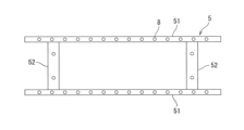
- the mold 5 is configured by sandwiching two short side copper plates 52 between two long side copper plates 51 .
- a plurality of temperature sensors 8 are provided inside the copper plate 51 and the copper plate 52 .
- a plurality of temperature sensors 8 are arranged in the horizontal direction at a plurality of positions in the casting direction of the mold 5 . That is, taking the copper plate 52 as an example as shown in FIG. 3, the temperature sensors 8 are provided at a plurality of casting direction positions with respect to the casting direction positions of the copper plate 52 (vertical direction in FIG. 3). . Also, at each casting direction position, a plurality of temperature sensors 8 are provided in the horizontal direction (horizontal direction in FIG. 3).
- the casting direction position where the temperature sensor 8 is provided is the same position for the copper plate 51 and the copper plate 52 .
- the mold 5 is configured so that the copper plate 52 on the short side can be moved in the horizontal direction in FIG. 2 so that the width of the cast slab 6 (slab width) can be adjusted.
- the temperature sensor 8 is not particularly limited as long as it can measure the temperature of the mold 5.
- a thermocouple or an optical fiber sensor may be used.
- an optical fiber is inserted from the upper end surface of the copper plates 51 and 52 in the casting direction (that is, the drawing direction) of the slab, parallel to the surface of the copper plates 51 and 52 on the molten steel side. .
- Such a method is preferably applied when the continuous casting equipment 1 is configured such that the copper plate 51 on the long side has a flat surface, such as a vertical bending slab continuous casting machine.
- the installation positions of the temperature measurement points of the temperature sensor 8 in the thickness direction of the copper plates 51 and 52 are such that the distance from the surface of the copper plates 51 and 52 on the molten steel side of all the installed temperature measurement points is the same, and each temperature measurement point is positioned between the surfaces of the copper plates 51 and 52 on the molten steel side and a cooling water slit (a channel through which cooling water passes for cooling the copper plates).
- the continuous casting facility 1 further has a determination device 9 that determines the start timing of continuous casting based on the measurement results of a plurality of temperature sensors 8, as shown in FIG.
- the determination device 9 is composed of an information processing device such as a computer, and an internal arithmetic processing device such as a CPU (Central Processing Unit) executes a computer program to operate as a hot water level estimation unit 91 and a withdrawal start determination unit 92. Function.
- the number of temperature sensors 8 provided at the same casting direction position is not particularly limited. ) is preferably 10 points or more.
- the start timing of continuous casting is determined according to the determination process of the process flow shown in FIG. 5, and continuous casting is started.
- the determination process shown in FIG. 5 is started at the timing when a start timing determination execution command is input to the determination device 9 .
- the start timing determination execution command is input by the timing of starting injection of the molten steel 2 from the submerged nozzle 4 into the mold 5 or by the operator's operation.
- step S100 the withdrawal start determination unit 92 outputs status 0 and timer 0 as initial values. There are three types of status: 0, 1, or 2. At the timing when status 2 is reached, an instruction to start pulling out the dummy bar is issued. Thereby, the process of step S100 is completed, and the determination process proceeds to the process of step S102.
- step S102 the temperatures of the copper plates 51 and 52 of the mold 5 are measured by the temperature sensor 8, and then the molten metal level estimation unit 91 obtains data on the measured temperatures of the copper plates 51 and 52 and the slab width. (measurement process). Thereby, the process of step S102 is completed, and the determination process proceeds to the process of step S104.
- the molten steel level estimation unit 91 uses the slab width data acquired in the process of step S102 and the installation coordinate data of the temperature sensors prepared in advance to The number N of temperature sensors within the width of the slab is counted.
- the mold 5 has two long side copper plates 51 and two short side copper plates 52 sandwiched between them.
- the temperature sensor 8 installed at the end of is located outside the copper plate 52 on the short side. Therefore, the temperature of the temperature sensor 8 of the copper plate 51 located outside the copper plate 52 is low even during casting. Therefore, with such a temperature sensor 8, it is difficult to determine whether the hot water surface has reached a certain level of the temperature sensor 8, and it should not be used for this determination. are pre-excluded. Thereby, the process of step S104 is completed, and the determination process proceeds to the process of step S106.
- the molten metal level estimating unit 10 detects the temperature of a plurality of temperature sensors 8 located at predetermined casting direction positions among the temperature sensors 8 extracted in the process of step S104. count the number of points m.
- the position in the casting direction is the distance from the upper ends of the copper plates 51 and 52 in the casting direction, but may be the distance in the vertical direction from the upper ends of the copper plates 51 and 52 .
- the predetermined position in the pouring direction is a position in the pouring direction that is suitable as the level of the molten metal surface in the mold 5 when continuous casting is started. is the casting direction position of This predetermined casting direction position is also referred to as a casting direction determination position. For example, in the example shown in FIG.
- the position of the fourth cut of the temperature sensor 8 from the upper end of the copper plate is defined as the pouring direction position (region indicated by the rectangular dashed line).
- N is preferably 10 points or more.
- the threshold value A is set as a value that can detect that the molten steel 2 has reached the casting direction position where the temperature sensor 8 of the copper plate 51, 52 is installed, and the distance of the temperature sensor 8 from the copper plate surface and the copper plate It is appropriately set depending on the materials of 51 and 52 and the like.
- the molten metal level estimating unit 91 determines whether the temperature of the temperature sensors 8 exceeding the threshold value A is a certain percentage or more among the plurality of temperature sensors 8 located at the casting direction determination position. That is, it is determined whether or not a value obtained by dividing the number m of sensors whose temperature exceeds the threshold A by the number N of points within the range of the slab width is equal to or greater than the threshold B. In this determination, it is determined whether or not the measured temperature is equal to or higher than a certain ratio at the casting direction determination position, thereby determining whether or not the surface of the molten steel 2 has reached the casting direction determination position. .
- step S108 if the value is less than the threshold value B, the determination process proceeds to step S110, and if the value is equal to or greater than the threshold value B, the determination process proceeds to step S112.
- the threshold value B is preferably set as a value at which it can be determined that the molten steel 2 has reached the casting direction determination position, and is set according to the detection accuracy of the temperature sensor 8 and the like.
- the molten metal surface before the start of drawing may vary greatly both in the width direction and the thickness direction. Therefore, when the threshold value B is infinitely close to 1, the timing for determining that the molten steel surface has reached the casting direction determination position is delayed, and the start of drawing is delayed, which may reduce productivity or cause molten steel to overflow from the mold. be.
- the threshold B is preferably set to a value of 0.5 or more and 0.9 or less.
- step S110 the withdrawal start determination unit 92 outputs status 0 and timer 0, and the determination process returns to the process of step S102.
- step S112 the withdrawal start determination unit 92 outputs status 1, and the determination process proceeds to the process of step S114.
- the withdrawal start determination unit 92 determines whether the timer is equal to or greater than the threshold value C. That is, in step S114, it is determined whether or not the state in which it is determined that the melt surface has reached the pouring direction determination position has continued for a predetermined time. The value of the timer indicates the duration of the state in which it is determined that the molten metal surface has reached the casting determination position. If it is less than the threshold value C, it is determined that it is not the start timing, and the determination process proceeds to step S116. On the other hand, if it is equal to or greater than the threshold value C, it is determined that it is time to start, and the determination process proceeds to step S118.
- the threshold value C is preferably set as a value at which it can be determined that a solidified shell has been sufficiently formed in the molten steel 2 that has reached the casting direction determination position to withstand the drawing.
- the threshold value C may be appropriately set based on the cooling capacity of the mold 5, past performance data, and the like. For example, from the opening of the sliding nozzle between the tundish 3 and the submerged nozzle 4 and the width and thickness of the slab, the average rate of rise of the molten metal level can be estimated. If the threshold value C is too large, molten steel may overflow from the mold.
- the threshold value C is set between 5 seconds and 15 seconds based on the function of the table value classified by the rising speed of the hot water level or the rising speed of the hot water level.
- step S116 the withdrawal start determination unit 92 outputs a value obtained by counting up the timer by one second, and the determination process returns to the process of step S102.
- temperature measurement by the temperature sensor 8 in the measurement process of step S102 is continuously performed at intervals of one second, and the series of processes from steps S102 to S116 are also performed at intervals of one second.
- step S118 the withdrawal start determination unit 92 outputs status 2, and the determination process proceeds to the process of step S120.
- the withdrawal start determination unit 92 issues a dummy bar withdrawal start instruction, and the series of determination processing ends.
- the judgment processing in steps S104 to S114 is also called a judgment step. That is, in this embodiment, the determination steps of steps S104 to S114 are performed after the measurement step of step S102.
- the start timing determination method determines the start timing according to the casting direction position of the molten steel surface, and uses the threshold value B and the threshold value C from the measurement result of the temperature sensor 8 within the range of the slab width.
- the temperature sensor 8 measures the temperature even at a position in the casting direction that is higher than the surface height of the molten steel due to the molten steel 2 being scattered in the mold 5. temperature may increase.
- the start timing determination method according to the present embodiment by performing determination using the threshold value B and the threshold value C, even in such a case, it is determined with high accuracy whether the molten metal surface has reached a predetermined casting direction position. be able to. Therefore, the start timing of continuous casting can be accurately determined.
- the start timing determination method uses the measurement results of a plurality of temperature sensors 8 arranged in the horizontal direction. As a result, it is possible to take into account large fluctuations in the surface of the molten steel in the width direction and the thickness direction. On the other hand, when the temperature sensor is arranged one-dimensionally in the casting direction, if there is a large fluctuation in the molten steel surface in the width direction or thickness direction, the molten steel surface cannot be detected accurately, and the start timing can be accurately determined. I can't.
- the start timing is determined using the measurement result of the temperature sensor 8 at the casting direction determination position, which is a predetermined casting direction position, but the present invention is not limited to such an example.
- the temperature measurement results of the temperature sensors 8 at a plurality of casting direction positions that is, the measurement results at the casting direction determination position and the measurement results at at least one casting direction position different from the casting direction determination position are used.
- the start timing may be determined by For example, the determination of the casting direction in the above embodiment and the temperature sensor 8 on the downstream side in the casting direction (lower side in FIG. 3) are performed in steps S100 to S118 for each position in the casting direction in the same manner as in the above embodiment. A process may be performed to calculate the status.
- a drawing start instruction may be issued. Further, the status may be calculated for each casting direction position for the temperature sensors 8 at the casting direction determination position and at least two casting direction positions on the upstream side and downstream side of the casting direction determination position. In this case, for example, even if the status at the casting direction determination position is not 2, if the status at the upstream and downstream casting direction positions is 2, the measurement at the casting direction determination position An error may have occurred in Therefore, in such a case, the status at the casting direction position on the upstream side and the downstream side may be set to 2, and the drawing start instruction may be issued.
- FIG. 6 shows an example of displaying the calculation result of the status for each casting direction position.
- the calculation result of the status for each casting direction position is indicated by vertically arranged square blocks, and the calculation result is displayed by changing the display of the block according to the status.
- the lower side shown in FIG. 6 is the downstream side in the casting direction, and the upper side is the upstream side in the casting direction.
- 22 temperature sensors 8 are installed at positions in the casting direction. It becomes the direction judgment position.
- the information indicating the molten steel surface level including the information indicating to which position in the casting direction the molten steel has reached in the mold 5 (position in the casting direction of the molten steel surface) is also referred to as the molten steel surface level information.
- an abnormality flag may be displayed as a status when the measured temperature is determined to be abnormal.
- the threshold for temperature abnormality upper and lower limits
- the temperature for determining the molten metal level threshold A
- the ratio for determining the molten metal level (threshold B) are set. You may make it display.
- N may not include the temperature sensor 8 that causes a defective temperature measurement, or the threshold value B may be adjusted.
- the temperature sensors 8 are provided at a plurality of positions in the casting direction, but the present invention is not limited to this example. As in the above embodiment, when determining the start timing of continuous casting only at the casting direction determination position, which is a predetermined casting direction position, the temperature sensor 8 may be provided only at the casting direction determination position.
- the measurement results of both the temperature sensor 8 provided on the copper plate 51 on the long side and the temperature sensor 8 provided on the copper plate 52 on the short side are used.
- the invention is not limited to such examples.
- the start timing may be determined using only the measurement result of the temperature sensor 8 provided on the copper plate 51 on the long side.
- the temperature sensor 8 may be provided only on the copper plate 51 on the long side.
- the determination device 9 has the device configuration shown in FIG. That is, in the present invention, the determination device 9 that determines the start timing of continuous casting may include a molten metal level estimation section 91 , a withdrawal start determination section 92 , and a plurality of temperature sensors 8 . Furthermore, in the above-described embodiment, the temperature value itself measured by the temperature sensor 8 is used, but the present invention is not limited to such an example. For example, by estimating the temperature distribution of the copper plate of the mold using an interpolation method such as linear interpolation or cubic spline interpolation, the casting direction determination position is It may be set at a position where the temperature sensor 8 does not exist.
- an interpolation method such as linear interpolation or cubic spline interpolation
- the present invention can also be applied to a continuous casting start determination system.
- the continuous casting start determination system 10 includes a determination server device 11 and a display terminal device 12 .
- the determination server device 11 and the display terminal device 12 are connected wirelessly or by wire through a network.
- the determination server device 11 has a temperature sensor 8 , a hot water level estimation unit 91 , a withdrawal start determination unit 92 , and a display data output unit 13 .
- the temperature sensor 8, the hot water level estimator 91, and the withdrawal start determination unit 92 are the same as in the above embodiment and other modifications.
- a plurality of temperature sensors 8 are provided in the mold width direction at a plurality of casting direction positions including a casting direction determination position, which is a predetermined casting direction position, on the copper plate of the mold 5 of the continuous casting equipment 1, and measure the temperature of the copper plate. Measure.
- the molten steel level estimator 91 estimates the casting direction position of the molten steel surface based on the measurement results of the plurality of temperature sensors 8 and the width of the slab 6 cast by the continuous casting facility 1 . Further, the drawing start determination unit 92 determines the start timing according to the estimated position of the pouring direction of the surface of the molten steel.
- the display data output unit 13 outputs to the display terminal device 12 the molten steel level information indicating the molten steel level including the estimated pouring direction position of the molten steel surface.
- the display terminal device 12 also has display data acquisition means 14 and display means 15 .
- the display data acquisition means 14 acquires the hot water level information from the determination server device 11 .
- the display means 15 displays the melt surface state for each position corresponding to the temperature data of the pouring direction position and the reference data for estimating the melt surface state based on the acquired melt surface level information.
- the reference data are the thresholds B and C used in steps S108 and S114.
- the display means 15 is a display device such as a monitor that displays the information shown in FIG. 6 as an image.
- the display means 15 may also display time-series data such as casting conditions, reference data, and copper plate temperature, as shown in FIGS. 8 and 9, which will be described later.
- the present inventors started continuous casting in an actual continuous casting facility 1 using the start timing determination method according to the above embodiment.
- the temperature sensor 8 was installed with the casting direction determination position directly below the meniscus position. Thirty-eight temperature sensors 8 were provided at casting direction determination positions. The number of points of the temperature sensor 8 within the range of the slab width during continuous casting was 30 points.
- Fig. 8 shows the measurement results of the temperature sensor 8 before and after the molten steel 2 is poured into the mold 5.
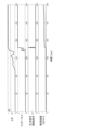
- FIG. 9 is a diagram showing an example in which the continuous casting start timing determination method according to the above embodiment is applied based on the temperature data of FIG.
- FIG. 9 shows the value obtained by dividing the number m of the temperature sensor 8 whose temperature exceeds the threshold value A by N, the status output by the withdrawal start determination unit 92, the withdrawal start instruction, and the time series change in the casting speed in actual operation. ing.
- the instruction to start pulling out the dummy bar could be issued at an appropriate timing, and no trouble occurred at the start of continuous casting.
Landscapes
- Engineering & Computer Science (AREA)
- Mechanical Engineering (AREA)
- Continuous Casting (AREA)
Abstract
L'objectif de la présente invention est de réaliser un procédé de détermination de temporisation de démarrage de coulée continue, un procédé de fonctionnement d'installation de coulée continue, un procédé de fabrication de brame, un dispositif de détermination, un système de détermination de démarrage de coulée continue et un équipement terminal d'affichage, permettant de déterminer avec précision une temporisation de démarrage de coulée continue. Ce procédé de détermination de temporisation de démarrage de coulée continue visant à déterminer une temporisation de démarrage de coulée continue, qui est une temporisation à laquelle un mannequin est retiré dans une installation de coulée continue (1), comprend : une étape de mesure visant à mesurer une température d'une plaque de cuivre d'un moule de coulée (5) de l'installation de coulée continue (1), à l'aide d'une pluralité de capteurs de température (8) disposés chacun dans une position de détermination de direction de coulée, qui est une position de direction de coulée prédéterminée, dans la plaque de cuivre ; et une étape de détermination visant à déterminer la temporisation de démarrage en fonction de la position de direction de coulée d'une surface de métal fondu d'acier fondu (2), estimée sur la base d'un résultat de mesure obtenu à l'étape de mesure, et d'une largeur d'une brame à couler à l'aide de l'installation de coulée continue (1).
Priority Applications (1)
| Application Number | Priority Date | Filing Date | Title |
|---|---|---|---|
| JP2023529885A JP7384323B1 (ja) | 2022-01-27 | 2023-01-25 | 連続鋳造のスタートタイミング判定方法、連続鋳造設備の操業方法、鋳片の製造方法、判定装置、連続鋳造スタート判定システム及び表示端末装置 |
Applications Claiming Priority (2)
| Application Number | Priority Date | Filing Date | Title |
|---|---|---|---|
| JP2022-011171 | 2022-01-27 | ||
| JP2022011171 | 2022-01-27 |
Publications (1)
| Publication Number | Publication Date |
|---|---|
| WO2023145786A1 true WO2023145786A1 (fr) | 2023-08-03 |
Family
ID=87471503
Family Applications (1)
| Application Number | Title | Priority Date | Filing Date |
|---|---|---|---|
| PCT/JP2023/002318 WO2023145786A1 (fr) | 2022-01-27 | 2023-01-25 | Procédé de détermination de temporisation de démarrage de coulée continue, procédé de fonctionnement d'installation de coulée continue, procédé de fabrication de brame, dispositif de détermination, système de détermination de démarrage de coulée continue, et équipement terminal d'affichage |
Country Status (2)
| Country | Link |
|---|---|
| JP (1) | JP7384323B1 (fr) |
| WO (1) | WO2023145786A1 (fr) |
Citations (4)
| Publication number | Priority date | Publication date | Assignee | Title |
|---|---|---|---|---|
| JPH1190589A (ja) * | 1997-09-16 | 1999-04-06 | Nippon Steel Corp | 連続鋳造のオートスタート方法 |
| JPH11123516A (ja) * | 1997-10-17 | 1999-05-11 | Sumitomo Metal Ind Ltd | 連続鋳造設備の操業方法 |
| JP2004276050A (ja) * | 2003-03-13 | 2004-10-07 | Sumitomo Metal Ind Ltd | 連続鋳造のスタート方法 |
| JP2012170999A (ja) * | 2011-02-23 | 2012-09-10 | Jfe Steel Corp | モールド内溶鋼湯面レベル制御方法 |
-
2023
- 2023-01-25 JP JP2023529885A patent/JP7384323B1/ja active Active
- 2023-01-25 WO PCT/JP2023/002318 patent/WO2023145786A1/fr active Application Filing
Patent Citations (4)
| Publication number | Priority date | Publication date | Assignee | Title |
|---|---|---|---|---|
| JPH1190589A (ja) * | 1997-09-16 | 1999-04-06 | Nippon Steel Corp | 連続鋳造のオートスタート方法 |
| JPH11123516A (ja) * | 1997-10-17 | 1999-05-11 | Sumitomo Metal Ind Ltd | 連続鋳造設備の操業方法 |
| JP2004276050A (ja) * | 2003-03-13 | 2004-10-07 | Sumitomo Metal Ind Ltd | 連続鋳造のスタート方法 |
| JP2012170999A (ja) * | 2011-02-23 | 2012-09-10 | Jfe Steel Corp | モールド内溶鋼湯面レベル制御方法 |
Also Published As
| Publication number | Publication date |
|---|---|
| JP7384323B1 (ja) | 2023-11-21 |
| JPWO2023145786A1 (fr) | 2023-08-03 |
Similar Documents
| Publication | Publication Date | Title |
|---|---|---|
| KR101443278B1 (ko) | 벌징 감지 모듈 및 이를 이용한 벌징 감지 방법 | |
| JP5673100B2 (ja) | ブレイクアウト予知方法 | |
| JP6950860B1 (ja) | ブレークアウト予知方法、連続鋳造機の操業方法、及び、ブレークアウト予知装置 | |
| JP4105839B2 (ja) | 連続鋳造における鋳型内鋳造異常検出方法 | |
| JP5092631B2 (ja) | 連続鋳造におけるブレークアウト検出方法及び装置、該装置を用いた鋼の連続鋳造方法、ブレークアウト防止装置 | |
| WO2023145786A1 (fr) | Procédé de détermination de temporisation de démarrage de coulée continue, procédé de fonctionnement d'installation de coulée continue, procédé de fabrication de brame, dispositif de détermination, système de détermination de démarrage de coulée continue, et équipement terminal d'affichage | |
| JP4112783B2 (ja) | 連続鋳造設備におけるブレークアウト検出方法 | |
| JP5884177B2 (ja) | 連続鋳造鋳片の凝固完了位置推定方法及び凝固完了位置推定装置 | |
| JP6435988B2 (ja) | 連続鋳造におけるブレークアウト予知方法、ブレークアウト防止方法、凝固シェル厚の測定方法、ブレークアウト予知装置およびブレークアウト防止装置 | |
| JPH01210160A (ja) | 連続鋳造における縦割れ予知方法 | |
| JP5707844B2 (ja) | 連続鋳造におけるブレークアウト検出方法及び装置 | |
| JP3103498B2 (ja) | 連続鋳造におけるブレイクアウトの予知および防止方法 | |
| JP6347236B2 (ja) | ブレークアウト予知方法、ブレークアウト予知装置および連続鋳造方法 | |
| JP5412872B2 (ja) | 連続鋳造におけるブレークアウト検出方法及び装置、該装置を用いた鋼の連続鋳造方法、ブレークアウト防止装置 | |
| JPH01143748A (ja) | 連続鋳造方法 | |
| JP5593801B2 (ja) | 連続鋳造のブレークアウト予知方法 | |
| WO2024070088A1 (fr) | Moule de coulée, équipement de commande et procédé de coulée continue pour acier | |
| WO2021256063A1 (fr) | Procédé de prédiction de rupture, procédé de fonctionnement d'un appareil de coulée continue et dispositif de prédiction de rupture | |
| JP7135728B2 (ja) | 鋳片品質推定方法、鋼材の製造方法、鋳片品質推定装置、およびプログラム | |
| JP4214818B2 (ja) | 拘束性ブレークアウト予知用温度センサの異常検知方法 | |
| JP3093586B2 (ja) | 連続鋳造鋳片の縦割れ検知方法 | |
| JP2022190572A (ja) | 連続鋳造における鋳片欠陥検知方法 | |
| JP2017024047A (ja) | 拘束性ブレークアウトの予知方法及び予知装置 | |
| JPWO2023145786A5 (fr) | ||
| JP3062723B2 (ja) | 鋳型内の凝固収縮による鋳片表面凹み形状の測定方法 |
Legal Events
| Date | Code | Title | Description |
|---|---|---|---|
| WWE | Wipo information: entry into national phase |
Ref document number: 2023529885 Country of ref document: JP |
|
| 121 | Ep: the epo has been informed by wipo that ep was designated in this application |
Ref document number: 23746996 Country of ref document: EP Kind code of ref document: A1 |