WO2023032500A1 - 二次電池用正極および二次電池 - Google Patents
二次電池用正極および二次電池 Download PDFInfo
- Publication number
- WO2023032500A1 WO2023032500A1 PCT/JP2022/028225 JP2022028225W WO2023032500A1 WO 2023032500 A1 WO2023032500 A1 WO 2023032500A1 JP 2022028225 W JP2022028225 W JP 2022028225W WO 2023032500 A1 WO2023032500 A1 WO 2023032500A1
- Authority
- WO
- WIPO (PCT)
- Prior art keywords
- positive electrode
- active material
- electrode active
- material particles
- layer
- Prior art date
- Legal status (The legal status is an assumption and is not a legal conclusion. Google has not performed a legal analysis and makes no representation as to the accuracy of the status listed.)
- Ceased
Links
Images




Classifications
-
- H—ELECTRICITY
- H01—ELECTRIC ELEMENTS
- H01M—PROCESSES OR MEANS, e.g. BATTERIES, FOR THE DIRECT CONVERSION OF CHEMICAL ENERGY INTO ELECTRICAL ENERGY
- H01M4/00—Electrodes
- H01M4/02—Electrodes composed of, or comprising, active material
- H01M4/36—Selection of substances as active materials, active masses, active liquids
- H01M4/48—Selection of substances as active materials, active masses, active liquids of inorganic oxides or hydroxides
- H01M4/52—Selection of substances as active materials, active masses, active liquids of inorganic oxides or hydroxides of nickel, cobalt or iron
- H01M4/525—Selection of substances as active materials, active masses, active liquids of inorganic oxides or hydroxides of nickel, cobalt or iron of mixed oxides or hydroxides containing iron, cobalt or nickel for inserting or intercalating light metals, e.g. LiNiO2, LiCoO2 or LiCoOxFy
-
- H—ELECTRICITY
- H01—ELECTRIC ELEMENTS
- H01M—PROCESSES OR MEANS, e.g. BATTERIES, FOR THE DIRECT CONVERSION OF CHEMICAL ENERGY INTO ELECTRICAL ENERGY
- H01M10/00—Secondary cells; Manufacture thereof
- H01M10/05—Accumulators with non-aqueous electrolyte
- H01M10/052—Li-accumulators
-
- H—ELECTRICITY
- H01—ELECTRIC ELEMENTS
- H01M—PROCESSES OR MEANS, e.g. BATTERIES, FOR THE DIRECT CONVERSION OF CHEMICAL ENERGY INTO ELECTRICAL ENERGY
- H01M4/00—Electrodes
- H01M4/02—Electrodes composed of, or comprising, active material
- H01M4/13—Electrodes for accumulators with non-aqueous electrolyte, e.g. for lithium-accumulators; Processes of manufacture thereof
- H01M4/131—Electrodes based on mixed oxides or hydroxides, or on mixtures of oxides or hydroxides, e.g. LiCoOx
-
- H—ELECTRICITY
- H01—ELECTRIC ELEMENTS
- H01M—PROCESSES OR MEANS, e.g. BATTERIES, FOR THE DIRECT CONVERSION OF CHEMICAL ENERGY INTO ELECTRICAL ENERGY
- H01M4/00—Electrodes
- H01M4/02—Electrodes composed of, or comprising, active material
- H01M4/36—Selection of substances as active materials, active masses, active liquids
- H01M4/362—Composites
- H01M4/366—Composites as layered products
-
- H—ELECTRICITY
- H01—ELECTRIC ELEMENTS
- H01M—PROCESSES OR MEANS, e.g. BATTERIES, FOR THE DIRECT CONVERSION OF CHEMICAL ENERGY INTO ELECTRICAL ENERGY
- H01M4/00—Electrodes
- H01M4/02—Electrodes composed of, or comprising, active material
- H01M4/36—Selection of substances as active materials, active masses, active liquids
- H01M4/48—Selection of substances as active materials, active masses, active liquids of inorganic oxides or hydroxides
- H01M4/50—Selection of substances as active materials, active masses, active liquids of inorganic oxides or hydroxides of manganese
- H01M4/505—Selection of substances as active materials, active masses, active liquids of inorganic oxides or hydroxides of manganese of mixed oxides or hydroxides containing manganese for inserting or intercalating light metals, e.g. LiMn2O4 or LiMn2OxFy
-
- H—ELECTRICITY
- H01—ELECTRIC ELEMENTS
- H01M—PROCESSES OR MEANS, e.g. BATTERIES, FOR THE DIRECT CONVERSION OF CHEMICAL ENERGY INTO ELECTRICAL ENERGY
- H01M4/00—Electrodes
- H01M4/02—Electrodes composed of, or comprising, active material
- H01M4/64—Carriers or collectors
- H01M4/66—Selection of materials
- H01M4/661—Metal or alloys, e.g. alloy coatings
-
- H—ELECTRICITY
- H01—ELECTRIC ELEMENTS
- H01M—PROCESSES OR MEANS, e.g. BATTERIES, FOR THE DIRECT CONVERSION OF CHEMICAL ENERGY INTO ELECTRICAL ENERGY
- H01M4/00—Electrodes
- H01M4/02—Electrodes composed of, or comprising, active material
- H01M2004/026—Electrodes composed of, or comprising, active material characterised by the polarity
- H01M2004/028—Positive electrodes
-
- Y—GENERAL TAGGING OF NEW TECHNOLOGICAL DEVELOPMENTS; GENERAL TAGGING OF CROSS-SECTIONAL TECHNOLOGIES SPANNING OVER SEVERAL SECTIONS OF THE IPC; TECHNICAL SUBJECTS COVERED BY FORMER USPC CROSS-REFERENCE ART COLLECTIONS [XRACs] AND DIGESTS
- Y02—TECHNOLOGIES OR APPLICATIONS FOR MITIGATION OR ADAPTATION AGAINST CLIMATE CHANGE
- Y02E—REDUCTION OF GREENHOUSE GAS [GHG] EMISSIONS, RELATED TO ENERGY GENERATION, TRANSMISSION OR DISTRIBUTION
- Y02E60/00—Enabling technologies; Technologies with a potential or indirect contribution to GHG emissions mitigation
- Y02E60/10—Energy storage using batteries
Definitions
- the present disclosure relates to positive electrodes for secondary batteries and secondary batteries.
- Secondary batteries especially lithium-ion secondary batteries, have high output and high energy density, so they are expected to be used as power sources for small consumer applications, power storage devices, and electric vehicles.
- Patent Document 1 discloses a positive electrode for a lithium secondary battery comprising a positive electrode mixture layer containing a lithium transition metal composite oxide as a positive electrode active material and a current collector foil, wherein the positive electrode mixture layer has an ⁇ -NaFeO 2 structure.
- the transition metal (Me) contains Co, Ni and Mn, the molar ratio Li/Me of lithium (Li) to the transition metal is greater than 1.2, and the molar ratio Mn/Me is Mn/Me ⁇ 0.5
- the above-mentioned lithium-nickel-manganese composite oxide has lower electron conductivity than conventionally used lithium-transition metal composite oxides containing cobalt (for example, lithium-nickel-cobalt-aluminum composite oxides). low.
- the current collecting property is lowered.
- the contact resistance with aluminum foil used as a current collector is also large.
- lithium-nickel-manganese composite oxides tend to have high resistance and large polarization.
- the expansion and contraction of the active material creates a gap between the active material and the aluminum foil, which tends to increase the resistance.
- a secondary battery using a lithium-nickel-manganese composite oxide as a positive electrode active material tends to deteriorate in charge-discharge characteristics.
- One aspect of the present disclosure includes a positive electrode current collector and a positive electrode mixture layer provided on the surface of the positive electrode current collector, the positive electrode current collector contains Al, and the positive electrode mixture layer includes , a first layer in contact with the positive electrode current collector, and a second layer in contact with the first layer, wherein the first layer includes first positive electrode active material particles having a particle size L, and the second The layer contains second positive electrode active material particles with a particle size R, contains third positive electrode active material particles with a particle size r at least at the interface between the first layer and the second layer, and the first positive electrode
- the active material particles contain a first lithium-transition metal composite oxide, the proportion of Co in metal elements other than Li contained in the first lithium-transition metal composite oxide is 2 atomic % or more, and the second The positive electrode active material particles contain a second lithium-transition metal composite oxide, and the second lithium-transition metal composite oxide does not contain Co or contains a metal other than Li contained in the second lithium-transition metal composite oxide.
- the proportion of Co in the elements is less than 2 atomic %
- the third positive electrode active material particles contain a third lithium-transition metal composite oxide
- the third lithium-transition metal composite oxide does not contain Co
- the present invention relates to a positive electrode for a secondary battery, wherein the ratio of Co to the metal elements other than Li contained in the third lithium-transition metal composite oxide is less than 2 atomic %, and R>L>r is satisfied.
- Another aspect of the present disclosure relates to a secondary battery including the positive electrode for a secondary battery, a separator, a negative electrode facing the positive electrode via the separator, and an electrolytic solution.
- FIG. 1 is a cross-sectional view schematically showing the structure of a positive electrode according to an embodiment of the present disclosure
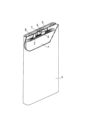
- FIG. 1 is a schematic perspective view of a partially cutaway secondary battery according to an embodiment of the present disclosure
- FIG. 4 is a graph showing charge/discharge curves of the battery of Example 1.
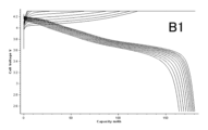
- FIG. 4 is a graph showing charge/discharge curves of a battery of Comparative Example 1.
- FIG. 4 is a graph showing changes in capacity retention ratios of batteries of Example 1 and Comparative Examples 1 and 2 for each charge/discharge cycle under conditions of charging to an overcharged state.
- 10 is a graph showing charge/discharge curves of the battery of Example 6.
- the present disclosure encompasses a combination of matters described in two or more claims arbitrarily selected from the multiple claims described in the attached claims. In other words, as long as there is no technical contradiction, the matters described in two or more claims arbitrarily selected from the multiple claims described in the attached claims can be combined.
- a positive electrode for a secondary battery includes a positive electrode current collector and a positive electrode mixture layer provided on the surface of the positive electrode current collector.
- the positive electrode current collector contains Al and is composed of a sheet-like conductive material.
- the positive electrode current collector is, for example, aluminum foil or aluminum alloy foil.
- the positive electrode mixture layer is carried on one or both surfaces of the positive electrode current collector.
- the positive electrode mixture layer is usually a layer (including a membrane or film) composed of a positive electrode mixture.
- the positive electrode mixture contains a positive electrode active material as an essential component.
- the positive electrode mixture layer includes a first layer in contact with the positive electrode current collector and a second layer in contact with the first layer.
- the first layer and the second layer are laminated in this order on the positive electrode current collector, and the first layer is sandwiched between the positive electrode current collector and the second layer.
- the first layer includes first positive electrode active material particles having a particle size L.
- the second layer includes second positive electrode active material particles having a particle size R.
- the third positive electrode active material particles having a particle size r are present at least at the interface between the first layer and the second layer.
- the third positive electrode active material particles may be contained in the entire second layer.
- the particle size L of the first positive electrode active material particles, the particle size R of the second positive electrode active material particles, and the particle size r of the third positive electrode active material particles satisfy the relationship R>L>r.
- the particle size L, the particle size R, and the particle size r are each measured from a cross-section in the thickness direction obtained by simultaneously cutting the positive electrode mixture layer and the positive electrode current collector, as will be described later.
- the first positive electrode active material particles contain a first lithium-transition metal composite oxide.
- the ratio of Co to the metal elements other than Li contained in the first lithium-transition metal composite oxide is 2 atomic % or more.
- the first lithium-transition metal composite oxide preferably contains Ni, Co and Al.
- Such a first lithium-transition metal composite oxide has high electron conductivity and excellent adhesion to the aluminum foil that is the positive electrode current collector. Therefore, since the first layer containing the first lithium-transition metal composite oxide is in contact with the positive electrode current collector, the current collecting property is improved, and the resistance between the first layer and the positive electrode current collector can be reduced. . As a result, polarization during rapid charging is alleviated, and charging/discharging characteristics are improved.
- the first layer is also in contact with the second layer containing the second positive electrode active material particles on the opposite side of the positive electrode current collector.
- the second layer contains a second lithium-transition metal composite oxide.
- the second lithium-transition metal composite oxide does not contain Co, or the ratio of Co to metal elements other than Li contained in the second lithium-transition metal composite oxide is less than 2 atomic %.
- a layer containing such a second lithium-transition metal composite oxide has a large resistance when it is brought into direct contact with an aluminum foil that is a positive electrode current collector.
- the second layer containing the second lithium-transition metal composite oxide does not directly contact the positive electrode current collector, but is in contact with the first layer.
- the resistance between the first layer and the second layer is small, polarization is suppressed, and charge/discharge characteristics are improved.
- the particle size R of the second positive electrode active material particles is larger than the particle size L of the first positive electrode active material particles (R>L), thick conductive paths are easily formed, and the first layer and the second layer.
- the third positive electrode active material particles having a particle size r smaller than the particle size L of the first positive electrode active material particles and the particle size r of the second positive electrode active material particles R separate the first layer and the second layer. at the interface between the first positive electrode active material particles and the second positive electrode active material particles.
- the third positive electrode active material particles contain a third lithium-transition metal composite oxide.
- the third lithium transition metal composite oxide does not contain Co, or the ratio of Co to the metal elements other than Li contained in the third lithium transition metal composite oxide is 2 atoms. %.
- the third lithium transition metal composite oxide may be a composite oxide having the same composition as the second lithium transition metal oxide except that the particle size is different, or a composite oxide different from the second lithium transition metal oxide. It may be an oxide.
- the third positive electrode active material particles may be contained inside the second layer in addition to the interface between the first layer and the second layer. In that case, the third positive electrode active material particles can be arranged in the second layer so as to fill the gaps between the second positive electrode active material particles. As a result, the filling rate of the positive electrode active material particles in the positive electrode mixture layer is increased, the capacity is increased, the resistance of the second layer is further decreased, and the charge/discharge characteristics are further improved.
- the third positive electrode active material particles may not be contained inside the first layer, and the third positive electrode active material particles may not be present at the interface between the positive electrode current collector and the first layer.
- the third positive electrode active material particles do not fill the gaps between the first positive electrode active material particles in the first layer, and the electrolyte can be held in the gaps between the first positive electrode active material particles. .
- a high capacity can be maintained even during rapid charging and discharging, and rate characteristics are improved.
- the third positive electrode active material particles are not present at the interface between the positive electrode current collector and the first layer means that when the cross section of the positive electrode is observed, the surface of the positive electrode current collector and one contacting this In the space formed between the first positive electrode active material particle and the adjacent first positive electrode active material particle (which particle is also in contact with the positive electrode current collector), the third positive electrode active material particle means that there are none or at most three.
- the particle size r of the third positive electrode active material particles and the particle size L of the first positive electrode active material particles preferably satisfy the relationship of r>0.155L.
- the third positive electrode active material particles at the interface between the first layer and the second layer are the first positive electrode active material particles. Intrusion into the first layer through gaps between substance particles is suppressed. Therefore, a space capable of holding the electrolytic solution is formed in the gap between the first positive electrode active material particles in the first layer, and the rate characteristics can be improved.
- the particle size L of the first positive electrode active material particles, the particle size R of the second positive electrode active material particles, and the particle size r of the third positive electrode active material particles are respectively the positive electrode mixture layer and the positive electrode current collector.
- the cross section may be formed using a cross section polisher (CP).
- the positive electrode mixture layer may be filled with a thermosetting resin and cured.
- the diameter (equivalent circle diameter) of a circle having the same area as the cross-sectional area of the particle (the area of the particle observed in the cross section of the positive electrode mixture layer) is obtained, and the maximum equivalent circle diameter is Let the value be the maximum diameter. Observe 10 or more particles and determine the maximum diameter.
- a cross section in the thickness direction of the second layer shows the second positive electrode active material particles and the third positive electrode active material particles.
- the second positive electrode active material particles and the third positive electrode active material particles can be distinguished from the cross-sectional image, the maximum diameter of each of the second positive electrode active material particles and the third positive electrode active material particles is obtained, R and r can be determined.
- two peaks, ie, a peak due to the second positive electrode active material particles and a peak due to the third positive electrode active material particles may appear. Two peaks are separated in the equivalent circle diameter distribution, and the maximum values are obtained from the separated peak due to the second positive electrode active material particles and the separated peak due to the separated third positive electrode active material particles, and R and r are calculated. you may ask.
- the D80 diameter (particle diameter at cumulative volume of 80%) in the volume-based particle size distribution of each of the material particles and the third positive electrode active material particles may be determined as L, R, and r.
- the volume-based particle size distribution can be measured by a laser diffraction scattering method. For example, "LA-750" manufactured by HORIBA, Ltd. can be used as the measuring device.
- the particle size distribution obtained by separating and collecting the positive electrode active material particles in the second layer includes the second positive electrode active material particles and a peak due to the third positive electrode active material particles appear.
- the peak due to the second positive electrode active material particles and the peak due to the third positive electrode active material particles may be separated from the particle size distribution, the D80 diameter may be determined from each peak in the particle size distribution, and R and r may be determined.
- the particle size R of the second positive electrode active material particles may be, for example, in the range of 10 to 30 ⁇ m, or may be in the range of 10 to 25 ⁇ m.
- the particle size r of the third positive electrode active material particles may be in the range of 1 to 5 ⁇ m, for example.
- composite oxide NCM lithium-nickel-cobalt-manganese composite oxide containing Ni, Co and Mn
- NCA lithium-nickel-cobalt-aluminum composite oxides containing Ni, Co and Al
- composite oxide NCMs include LiNi 0.5 Co 0.2 Mn 0.3 O 2 and LiNi 1/3 Co 1/3 Mn 1/3 O 2 .
- the composite oxide NCA is Li ⁇ Ni 1-xy Co x Al y O 2 (where 0.95 ⁇ 1.05, 0.02 ⁇ x ⁇ 0.1, 0.02 ⁇ x+y ⁇ 1 ) may be a composite oxide represented by In the above formula, the ⁇ value, which indicates the molar ratio of lithium, is the value when discharged until the positive electrode potential reaches 2.5 V with respect to the Li counter electrode, and increases or decreases due to charging and discharging.
- lithium-nickel containing Ni and Mn - manganese composite oxide (hereinafter referred to as "composite oxide NM").
- composite oxide NM lithium-nickel containing Ni and Mn - manganese composite oxide
- the ratio of Ni and Mn to the metal elements other than Li contained in the composite oxide NM may be 98 atomic % or more.
- the composite oxide NM may be a composite oxide represented by Li ⁇ Ni 1-x Mn x O 2 (where 0.95 ⁇ 1.05 and 0 ⁇ x ⁇ 0.2).
- FIG. 1 is a cross-sectional view schematically showing the structure of the positive electrode for a secondary battery according to this embodiment.
- the positive electrode 10 includes a positive electrode current collector 11 and a positive electrode mixture layer 12 provided on the surface of the positive electrode current collector 11 .
- FIG. 1 shows a part of a cross section in the thickness direction of the positive electrode mixture layer 12 and the positive electrode current collector 11 simultaneously cut.
- the positive electrode mixture layers 12 may be formed on both main surfaces of the positive electrode current collector 11 .
- FIG. 1 shows a part of one main surface side of the positive electrode current collector 11 and a part of the positive electrode mixture layer 12 formed on the main surface, and the other main surface side of the positive electrode current collector 11. is omitted.
- the positive electrode mixture layer 12 includes a first layer 12A in contact with the positive electrode current collector 11 and a second layer 12B in contact with the first layer 12A on the side facing the positive electrode current collector 11 with the first layer interposed therebetween.
- the first layer 12A includes first positive electrode active material particles P1.
- the second layer 12B includes second positive electrode active material particles P2 and third positive electrode active material particles P3.
- the particle size L of the first positive electrode active material particles P1 is smaller than the particle size R of the second positive electrode active material particles P2 and larger than the particle size of the third positive electrode active material P3 (R>L>r). .
- the positive electrode current collector 11 is aluminum foil.
- the first positive electrode active material particles P1 are a lithium-nickel-cobalt-aluminum composite oxide (composite oxide NCA), and a part of the first positive electrode active material particles P1 is a positive electrode current collector. It is in contact with the positive electrode current collector 11 so as to be embedded in the aluminum foil 11 . As a result, the first positive electrode active material particles P1 come into surface contact with the positive electrode current collector 11, and the resistance between the positive electrode current collector 11 and the first layer 12A decreases.
- composite oxide NCA lithium-nickel-cobalt-aluminum composite oxide
- the third positive electrode active material particles P3 are present in the gaps between .
- the second positive electrode active material particles P2 are in direct contact with the first positive electrode active material particles P1, and are in contact with the first positive electrode active material particles P1 via the third positive electrode active material particles P3.
- the third positive electrode active material particles P3 are not interposed in the gaps between the first positive electrode active material particles P1 in the first layer.
- the gaps between the first positive electrode active material particles P1 are filled with the electrolytic solution. As a result, rate characteristics can be improved.
- the three first positive electrode active material particles P1 forming a triangular lattice in the plane form
- the second positive electrode active material particles P2 and the third positive electrode active material particles P3 here are lithium-nickel-manganese composite oxides (composite oxides NM).
- composite oxides NM lithium-nickel-manganese composite oxides
- the filling density of the positive electrode active material in the second layer can be increased. can increase the capacity.
- FIG. 1 shows the positive electrode mixture layer 12 having a two-layer structure of the first layer 12A and the second layer 12B, another positive electrode active material layer exists on the second layer 12B. good too.
- a secondary battery has, for example, the positive electrode, a separator, a negative electrode facing the positive electrode with the separator interposed therebetween, and an electrolytic solution.
- the positive electrode includes a positive electrode current collector and a positive electrode mixture layer formed on the surface of the positive electrode current collector and containing a positive electrode active material.
- the positive electrode active material layer contains a positive electrode active material as an essential component, and may contain a binder, a conductive agent, and the like as optional components. Known materials can be used as the binder, conductive agent, and thickener.
- the positive electrode mixture layer has a laminated structure of at least two layers, the first layer in contact with the positive electrode current collector and the second layer in contact with the first layer.
- the thickness T1 of the first layer is, for example, 3 to 30 ⁇ m.
- the thickness T2 of the second layer is, for example, 10-150 ⁇ m.
- the ratio of the thickness T1 of the first layer to the thickness T2 of the second layer: T1/T2 is, for example, 0.1 to 1.0.
- the first layer contains the first positive electrode active material particles having the particle size L as described above.
- the second layer includes second positive electrode active material particles having a particle size R.
- Third positive electrode active material particles having a particle size r are present at least at the interface between the first layer and the second layer.
- the third positive electrode active material particles may be dispersed in the second layer together with the second positive electrode active material particles.
- the first layer is formed by, for example, a process of applying a first positive electrode slurry in which a first positive electrode mixture containing first positive electrode active material particles, a binder, etc. is dispersed in a dispersion medium to the surface of the positive electrode current collector. It can be formed by a method having For the second layer, for example, a second positive electrode slurry in which a second positive electrode mixture containing second positive electrode active material particles, third positive electrode active material particles, a binder, etc. is dispersed in a dispersion medium is applied to the first positive electrode slurry. It can be formed by a method including a process of coating the surface of the positive electrode slurry. The laminated coating film after drying may be rolled if necessary. The first positive electrode slurry and the second positive electrode slurry may be simultaneously applied to the surface of the positive electrode current collector using a two-fluid nozzle.
- the second positive electrode active material particles account for the total of the second positive electrode active material particles and the third positive electrode active material particles.
- the proportion may be from 50% to 90% or from 65% to 85% by mass.
- a lithium-transition metal composite oxide containing lithium and Ni and having a layered rock salt crystal structure can be used as the first to third positive electrode active material particles.
- the metal element other than lithium and the ratio of the metal element in the lithium-transition metal composite oxide can be changed.
- Ni-containing lithium-transition metal composite oxides are advantageous for increasing capacity and reducing costs. From the viewpoint of obtaining a high capacity, it is desirable that the proportion of Ni in the metal elements other than Li contained in the lithium-transition metal composite oxide is 80 atomic % or more.
- the ratio of Ni to the metal elements other than Li may be 85 atomic % or more, or 90 atomic % or more.
- the ratio of Ni to the metal elements other than Li is desirably 95 atomic % or less, for example. When limiting the range, these upper and lower limits can be combined arbitrarily.
- the lithium transition metal composite oxide may contain Co, Mn and/or Al. Co, Mn and Al contribute to stabilization of the crystal structure of the composite oxide with a high Ni content. However, from the viewpoint of manufacturing cost reduction, it is desirable that the Co content is as low as possible. A composite oxide with a low Co content or no Co may contain Mn and Al. From the viewpoint of manufacturing cost reduction, it is desirable to limit the proportion of Co to metal elements other than Li in the lithium-transition metal composite oxide to less than 2 atomic %.
- the lithium transition metal composite oxide may be represented, for example, by the general formula: Li ⁇ Ni 1-x1-x2-yz Co x1 Mn x2 Al y Me z O 2+ ⁇ .
- the general formula is 0.95 ⁇ 1.05, 0 ⁇ x1 ⁇ 0.1, 0 ⁇ x2 ⁇ 0.5, 0 ⁇ y ⁇ 0.1, 0 ⁇ z ⁇ 0.1, 0. 5 ⁇ 1-x1-x2-yz and -0.05 ⁇ 0.05
- Me is an element other than Li, Ni, Mn, Al, Co and oxygen.
- the ⁇ value which indicates the molar ratio of lithium, is the value when the positive electrode potential is charged to 2.5 V based on the Li counter electrode, and increases or decreases due to charging and discharging.
- Me includes Nb, Zr, B, Mg, Fe, Cu, Zn, Sn, Na, K, Ba, Sr, Ca, W, Mo, Si , Ti, Fe and Cr.
- the first lithium-transition metal composite oxide used for the first positive electrode active material particles is Li ⁇ Ni 1-x-y Co x Al y O 2 (where 0.
- a lithium-nickel-cobalt-aluminum composite oxide (composite oxide NCA) represented by 02 ⁇ x ⁇ 0.1, 0.02 ⁇ x+y ⁇ 1) can be used.
- the composite oxide NCA contains a relatively large amount of Co, it has high electron conductivity and good adhesion to the positive electrode current collector, so that the contact resistance can be reduced.
- by reducing the ratio of the thickness of the first layer to the thickness of the positive electrode mixture layer it is possible to minimize the increase in manufacturing cost due to the inclusion of Co.
- the production cost can be reduced by limiting the ratio of Co to the metal elements other than Li to less than 2 atomic %.
- the lithium-transition metal composite oxides as the second lithium-transition metal composite oxide used for the second positive electrode active material particles or the third lithium-transition metal composite oxide used for the third positive electrode active material particles, A lithium-manganese composite oxide (composite oxide NM) represented by Li ⁇ Ni 1-x Mn x (where 0 ⁇ x ⁇ 0.2) can be used.
- composite oxide NM composite oxide represented by Li ⁇ Ni 1-x Mn x (where 0 ⁇ x ⁇ 0.2)
- the shape and thickness of the positive electrode current collector may be, for example, 5 ⁇ m or more and 20 ⁇ m or less.
- materials for the positive electrode current collector include stainless steel, aluminum, aluminum alloys, and titanium.
- the negative electrode includes, for example, a negative electrode current collector and a negative electrode active material layer formed on the surface of the negative electrode current collector.
- the negative electrode active material layer can be formed, for example, by applying a negative electrode slurry in which a negative electrode mixture containing a negative electrode active material, a binder and the like is dispersed in a dispersion medium on the surface of the negative electrode current collector and drying the slurry. The dried coating film may be rolled if necessary. That is, the negative electrode active material may be the negative electrode mixture layer. Alternatively, a lithium metal foil or a lithium alloy foil may be attached to the negative electrode current collector as the negative electrode active material layer.
- the negative electrode active material layer may be formed on one surface of the negative electrode current collector, or may be formed on both surfaces.
- the negative electrode active material layer contains the negative electrode active material as an essential component, and may contain a binder, a conductive agent, a thickener, etc. as optional components. Known materials can be used as the binder, conductive agent, and thickener.
- Negative electrode active materials include materials that electrochemically absorb and release lithium ions, lithium metal, and lithium alloys. Carbon materials, alloy materials, and the like are used as materials that electrochemically occlude and release lithium ions. Examples of carbon materials include graphite, graphitizable carbon (soft carbon), and non-graphitizable carbon (hard carbon). Among them, graphite is preferable because it has excellent charging/discharging stability and low irreversible capacity. Examples of alloy materials include those containing at least one metal capable of forming an alloy with lithium, such as silicon, tin, silicon alloys, tin alloys, and silicon compounds. Silicon oxide, tin oxide, or the like in which these are combined with oxygen may also be used.
- a lithium ion conductive phase and a silicon composite material in which silicon particles are dispersed in the lithium ion conductive phase can be used.
- the lithium ion conductive phase for example, a silicon oxide phase, a silicate phase, a carbon phase, or the like can be used.
- a major component (eg, 95-100% by weight) of the silicon oxide phase can be silicon dioxide.
- a composite material composed of a silicate phase and silicon particles dispersed in the silicate phase is preferable in terms of high capacity and low irreversible capacity.
- a silicate phase containing lithium hereinafter also referred to as a lithium silicate phase
- a silicate phase containing lithium is preferable because of its small irreversible capacity and high initial charge/discharge efficiency.
- the lithium silicate phase may be an oxide phase containing lithium (Li), silicon (Si), and oxygen (O), and may contain other elements.
- the atomic ratio of O to Si: O/Si in the lithium silicate phase is greater than 2 and less than 4, for example.
- O/Si is greater than 2 and less than 3.
- the atomic ratio of Li to Si in the lithium silicate phase: Li/Si is greater than 0 and less than 4, for example.
- Elements other than Li, Si and O that can be contained in the lithium silicate phase include, for example, iron (Fe), chromium (Cr), nickel (Ni), manganese (Mn), copper (Cu), molybdenum (Mo), Examples include zinc (Zn) and aluminum (Al).
- the carbon phase can be composed of, for example, amorphous carbon with low crystallinity (that is, amorphous carbon).
- Amorphous carbon may be, for example, hard carbon, soft carbon, or otherwise.
- a non-porous conductive substrate metal foil, etc.
- a porous conductive substrate meh body, net body, punching sheet, etc.
- materials for the negative electrode current collector include stainless steel, nickel, nickel alloys, copper, and copper alloys.
- the electrolyte contains a solvent and a solute dissolved in the solvent.
- a solute is an electrolyte salt that ionically dissociates in the electrolyte.
- Solutes can include, for example, lithium salts.
- Components of electrolytes other than solvents and solutes are additives.
- the electrolyte may contain various additives.
- aqueous solvent or a non-aqueous solvent is used as the solvent.
- non-aqueous solvents include cyclic carbonates, chain carbonates, cyclic carboxylates, chain carboxylates, and the like.
- Cyclic carbonates include propylene carbonate (PC), ethylene carbonate (EC), vinylene carbonate (VC) and the like.
- Chain carbonates include diethyl carbonate (DEC), ethyl methyl carbonate (EMC), dimethyl carbonate (DMC) and the like.
- cyclic carboxylic acid esters include ⁇ -butyrolactone (GBL) and ⁇ -valerolactone (GVL).
- Chain carboxylic acid esters include methyl acetate, ethyl acetate, propyl acetate, methyl propionate (MP), ethyl propionate (EP) and the like.
- the non-aqueous solvent may be used singly or in combination of two or more.
- lithium salts include lithium salts of chlorine-containing acids ( LiClO4 , LiAlCl4 , LiB10Cl10 , etc.), lithium salts of fluorine-containing acids ( LiPF6 , LiPF2O2 , LiBF4 , LiSbF6 , LiAsF6 , LiCF3SO3 , LiCF3CO2 , etc.), lithium salts of fluorine-containing acid imides ( LiN( FSO2 ) 2 , LiN( CF3SO2 ) 2 , LiN( CF3SO2 ) ( C4F9SO 2 ) , LiN ( C2F5SO2 ) 2, etc.), lithium halides (LiCl, LiBr, LiI, etc.) can be used. Lithium salts may be used singly or in combination of two or more.
- the concentration of the lithium salt in the electrolytic solution may be 1 mol/liter or more and 2 mol/liter or less, or may be 1 mol/liter or more and 1.5 mol/liter or less.
- the lithium salt concentration is not limited to the above.
- Separator It is desirable to interpose a separator between the positive electrode and the negative electrode.
- the separator has high ion permeability and moderate mechanical strength and insulation.
- a microporous thin film, a woven fabric, a nonwoven fabric, or the like can be used as the separator.
- Polyolefins such as polypropylene and polyethylene are preferable as the material of the separator.
- an electrode group in which a positive electrode and a negative electrode are wound with a separator interposed therebetween, is housed in an outer package together with an electrolytic solution.
- an electrode group in which a positive electrode and a negative electrode are wound with a separator interposed therebetween
- an electrolytic solution it is not limited to this, and other forms of electrode groups may be applied.
- a laminated electrode group in which a positive electrode and a negative electrode are laminated with a separator interposed therebetween may be used.
- the shape of the battery is also not limited, and may be, for example, cylindrical, square, coin, button, laminate, or the like.
- the battery includes a prismatic battery case 4 with a bottom, and an electrode group 1 and an electrolytic solution (not shown) housed in the battery case 4 .
- the electrode group 1 has a long strip-shaped negative electrode, a long strip-shaped positive electrode, and a separator interposed therebetween.
- the negative electrode current collector of the negative electrode is electrically connected to a negative electrode terminal 6 provided on a sealing plate 5 via a negative electrode lead 3 .
- the negative electrode terminal 6 is insulated from the sealing plate 5 by a resin gasket 7 .
- the positive current collector of the positive electrode is electrically connected to the rear surface of the sealing plate 5 via the positive lead 2 . That is, the positive electrode is electrically connected to the battery case 4 which also serves as a positive electrode terminal.
- the peripheral edge of the sealing plate 5 is fitted into the open end of the battery case 4, and the fitted portion is laser-welded.
- the sealing plate 5 has an injection hole for a non-aqueous electrolyte, which is closed by a sealing plug 8 after the
- Example 1 [Preparation of positive electrode] A lithium-cobalt-aluminum composite oxide (LiNi 0.91 Co 0.05 Al 0.04 O 2 ) was prepared as the first positive electrode active material particles.
- Lithium-nickel-manganese composite oxides (LiNi 0.8 Mn 0.2 O 2 ) having different average particle diameters were prepared as the second positive electrode active material particles and the third positive electrode active material particles.
- the particle diameters R and r of the second and third positive electrode active material particles measured as the D80 diameter in the volume-based particle size distribution by a laser diffraction scattering method were 15 ⁇ m and 1 ⁇ m, respectively.
- a first positive electrode slurry was prepared.
- the first positive electrode slurry is applied to the surface of an aluminum foil that is a positive electrode current collector, the coating is dried, and then the second positive electrode slurry is applied so as to cover the coating of the first positive electrode slurry.
- the film was dried and rolled to form a 100 ⁇ m thick positive electrode mixture layer on an aluminum foil.
- a cross section in the thickness direction is formed by simultaneously cutting the positive electrode mixture layer and the positive electrode current collector, and an SEM image of the cross section is taken.
- the maximum diameter (maximum equivalent circle diameter) of the second and third positive electrode active material particles was obtained.
- L, R, and r determined as the maximum value of the equivalent circle diameter approximately matched L, R, and r, respectively, determined as the D80 diameter in the volume-based particle size distribution.
- a positive electrode for evaluation was obtained by cutting the positive electrode into a predetermined shape.
- the positive electrode was provided with a 20 mm ⁇ 20 mm region functioning as a positive electrode and a 5 mm ⁇ 5 mm connecting region with a tab lead. After that, the positive electrode material mixture layer formed on the connection region was scraped off to expose the positive electrode current collector. After that, the exposed portion of the positive electrode current collector was connected to the positive electrode tab lead, and a predetermined region of the outer circumference of the positive electrode tab lead was covered with an insulating tab film.
- a negative electrode was prepared by attaching a lithium metal foil (thickness: 300 ⁇ m) to one side of an electrolytic copper foil that was a negative electrode current collector.
- a negative electrode was cut into the same shape as the positive electrode to obtain a negative electrode for evaluation.
- the lithium metal foil formed on the connection region formed in the same manner as the positive electrode was peeled off to expose the negative electrode current collector. After that, the exposed portion of the negative electrode current collector was connected to the negative electrode tab lead in the same manner as the positive electrode, and a predetermined region of the outer periphery of the negative electrode tab lead was covered with an insulating tab film.
- LiPF6 was added as a lithium salt to a mixed solvent containing ethylene carbonate (EC), ethyl methyl carbonate (EMC) and dimethyl carbonate (DMC) at a volume ratio of 20:5:75 to prepare an electrolytic solution.
- EC ethylene carbonate
- EMC ethyl methyl carbonate
- DMC dimethyl carbonate
- a battery for evaluation was produced using the positive electrode and the negative electrode for evaluation.
- the positive electrode and the negative electrode were opposed to each other with the separator interposed therebetween so that the positive electrode mixture layer and the negative electrode mixture layer overlapped to obtain an electrode plate assembly.
- an Al laminate film (thickness: 100 ⁇ m) cut into a rectangle of 60 ⁇ 90 mm was folded in half, and the end of the long side of 60 mm was heat-sealed at 230° C. to form a cylinder of 60 ⁇ 45 mm.
- the produced electrode plate group was placed in a cylinder, and heat sealing was performed at 230° C. with the end surface of the Al laminate film aligned with the insulating tab film of each tab lead.
- 0.3 cm 3 of a non-aqueous electrolyte is injected from the short side of the Al laminate film that is not heat-sealed, and after the injection, it is left to stand under a reduced pressure of 0.06 MPa for 5 minutes.
- the layers were impregnated with electrolyte.
- the end face of the Al laminate film on the injected side was heat-sealed at 230° C. to prepare battery A1 for evaluation.
- the evaluation cell was produced in a dry environment with a dew point of ⁇ 50° C. or less.
- Example 1 In the preparation of the positive electrode, only the second positive electrode slurry of Example 1 was applied to the surface of the aluminum foil as the positive electrode current collector, and in the same manner as in Example 1, it had the same theoretical capacity as in Example 1 and had a thickness of 100 ⁇ m. A positive electrode having a positive electrode mixture layer was obtained. A battery B1 for evaluation was produced in the same manner as in Example 1 using this positive electrode.
- a positive electrode slurry was prepared by mixing 98 parts by mass of a positive electrode active material mixed at a mass ratio, 1 part by mass of acetylene black (AB), 1 part by mass of polyvinylidene fluoride (PVDF), and an appropriate amount of NMP.
- a positive electrode having a positive electrode mixture layer with a thickness of 100 ⁇ m was obtained in the same manner except that only the positive electrode slurry was applied to the surface of an aluminum foil as a positive electrode current collector.
- the contents of the first to third positive electrode active material particles in the positive electrode mixture layer are the same as those of the positive electrode of Example 1.
- the positive electrode mixture layer does not have the first layer and the second layer, and the first to third positive electrode active material particles are dispersed in the positive electrode mixture layer.
- a rest period between charging and discharging was set to 20 minutes, and charging and discharging were repeated 10 cycles under the above charging and discharging conditions in an environment of 25°C.
- the discharge capacity Cn was obtained with respect to the charge capacity C0 in the first cycle, and Cn/ C0 ⁇ 100 was evaluated as the capacity retention rate.
- FIG. 3A shows the measurement results of the charge-discharge curve of the battery A1.
- FIG. 3B shows the measurement results of the charge/discharge curve of battery B1.
- the voltage during charging tends to increase and the discharge capacity tends to decrease as the charge/discharge cycle is repeated.
- FIG. 3A compared with FIG. 3B, the increase in charge voltage due to repeated charge/discharge cycles is suppressed, and the polarization is reduced.
- a decrease in discharge capacity due to repeated charge-discharge cycles is suppressed.
- FIG. 4 shows changes in the capacity retention rate of batteries A1, B1 and B2 for each charge/discharge cycle.
- charging is performed at a high voltage of 4.5 V until an overcharged state is reached in the charging/discharging cycle, and the environment is such that Mn in the lithium-nickel-manganese composite oxide is easily eluted.
- the decrease in discharge capacity due to repeated charge-discharge cycles is suppressed compared to batteries B1 and B2.
- Example 2 to 6 Comparative Example 3>
- the particle sizes of the first to third positive electrode active material particles were changed as shown in Table 1.
- Batteries A2 to A6 and B3 for evaluation were produced in the same manner as in Example 1, and the discharge rate characteristics were evaluated by the method described below.
- Table 1 shows the evaluation results of the discharge rate characteristics of the batteries A1 to A6 and B3 together with the particle sizes of the first to third positive electrode active material particles. Batteries A1 to A5 satisfying R>L>r and r>0.155L were able to maintain high discharge rate characteristics.
- Fig. 5 shows the charge/discharge curve of Battery A6. Since the battery A6 satisfies R>L>r, it is inferior to the battery A1, but the increase in the charge voltage due to the repetition of the charge-discharge cycle is suppressed, and the decrease in the discharge capacity due to the repetition of the charge-discharge cycle is suppressed. Suppressed. However, since r>0.155L was not satisfied, the discharge rate characteristics were lower than those of Batteries A1 to A5.
- a secondary battery according to the present disclosure it is possible to provide a secondary battery that has a high capacity and is advantageous in improving charge/discharge characteristics.
- a secondary battery according to the present disclosure is useful as a main power source for mobile communication devices, electric vehicles, hybrid vehicles, portable electronic devices, and the like.
Landscapes
- Chemical & Material Sciences (AREA)
- Chemical Kinetics & Catalysis (AREA)
- Electrochemistry (AREA)
- General Chemical & Material Sciences (AREA)
- Engineering & Computer Science (AREA)
- Materials Engineering (AREA)
- Inorganic Chemistry (AREA)
- Manufacturing & Machinery (AREA)
- Composite Materials (AREA)
- Battery Electrode And Active Subsutance (AREA)
- Secondary Cells (AREA)
Priority Applications (4)
| Application Number | Priority Date | Filing Date | Title |
|---|---|---|---|
| EP22864088.4A EP4398331A4 (en) | 2021-08-31 | 2022-07-20 | POSITIVE ELECTRODE FOR RECHARGEABLE BATTERIES AND RECHARGEABLE BATTERY |
| CN202280057592.3A CN117836967A (zh) | 2021-08-31 | 2022-07-20 | 二次电池用正极和二次电池 |
| US18/687,449 US20250132325A1 (en) | 2021-08-31 | 2022-07-20 | Positive electrode for secondary batteries, and secondary battery |
| JP2023545147A JPWO2023032500A1 (https=) | 2021-08-31 | 2022-07-20 |
Applications Claiming Priority (2)
| Application Number | Priority Date | Filing Date | Title |
|---|---|---|---|
| JP2021-141538 | 2021-08-31 | ||
| JP2021141538 | 2021-08-31 |
Publications (1)
| Publication Number | Publication Date |
|---|---|
| WO2023032500A1 true WO2023032500A1 (ja) | 2023-03-09 |
Family
ID=85412096
Family Applications (1)
| Application Number | Title | Priority Date | Filing Date |
|---|---|---|---|
| PCT/JP2022/028225 Ceased WO2023032500A1 (ja) | 2021-08-31 | 2022-07-20 | 二次電池用正極および二次電池 |
Country Status (5)
| Country | Link |
|---|---|
| US (1) | US20250132325A1 (https=) |
| EP (1) | EP4398331A4 (https=) |
| JP (1) | JPWO2023032500A1 (https=) |
| CN (1) | CN117836967A (https=) |
| WO (1) | WO2023032500A1 (https=) |
Families Citing this family (2)
| Publication number | Priority date | Publication date | Assignee | Title |
|---|---|---|---|---|
| CN119993978B (zh) * | 2025-04-11 | 2025-09-02 | 宁德时代新能源科技股份有限公司 | 电池单体、电池装置、用电装置及储能装置 |
| CN119993999B (zh) * | 2025-04-11 | 2025-10-10 | 宁德时代新能源科技股份有限公司 | 电池单体、电池装置、用电装置及储能装置 |
Citations (7)
| Publication number | Priority date | Publication date | Assignee | Title |
|---|---|---|---|---|
| JP2009026599A (ja) * | 2007-07-19 | 2009-02-05 | Toyota Motor Corp | 正電極板、リチウムイオン二次電池、車両、および、電池搭載機器 |
| JP2010033924A (ja) * | 2008-07-30 | 2010-02-12 | Nec Tokin Corp | リチウムイオン二次電池用正極、およびそれを用いたリチウムイオン二次電池 |
| JP2013214493A (ja) * | 2012-04-03 | 2013-10-17 | Samsung Corning Precision Materials Co Ltd | リチウムイオン2次電池用リチウムマンガン酸化物正極活物質およびそれを含むリチウムイオン2次電池 |
| JP2015115244A (ja) | 2013-12-13 | 2015-06-22 | 株式会社Gsユアサ | リチウム二次電池用正極、リチウム二次電池、バッテリーモジュール、及びバッテリーモジュールを搭載した自動車 |
| CN111554965A (zh) * | 2020-05-13 | 2020-08-18 | 金妍 | 一种锂离子电池正极的制备方法 |
| CN112259723A (zh) * | 2020-10-29 | 2021-01-22 | 苏州彼欧智能科技有限公司 | 一种锂离子电池正极的制备方法 |
| CN112382737A (zh) * | 2020-11-12 | 2021-02-19 | 苏州酷卡环保科技有限公司 | 一种锂离子电池阴极的制备方法 |
Family Cites Families (3)
| Publication number | Priority date | Publication date | Assignee | Title |
|---|---|---|---|---|
| WO2012044132A2 (ko) * | 2010-09-30 | 2012-04-05 | 주식회사 엘지화학 | 리튬 이차전지용 양극 및 이를 구비한 리튬 이차전지 |
| JP6469450B2 (ja) * | 2014-02-27 | 2019-02-13 | パナソニック株式会社 | 非水電解質二次電池用正極及び非水電解質二次電池 |
| CN110660961B (zh) * | 2018-06-28 | 2021-09-21 | 宁德时代新能源科技股份有限公司 | 正极片及锂离子电池 |
-
2022
- 2022-07-20 WO PCT/JP2022/028225 patent/WO2023032500A1/ja not_active Ceased
- 2022-07-20 US US18/687,449 patent/US20250132325A1/en active Pending
- 2022-07-20 EP EP22864088.4A patent/EP4398331A4/en active Pending
- 2022-07-20 JP JP2023545147A patent/JPWO2023032500A1/ja active Pending
- 2022-07-20 CN CN202280057592.3A patent/CN117836967A/zh active Pending
Patent Citations (7)
| Publication number | Priority date | Publication date | Assignee | Title |
|---|---|---|---|---|
| JP2009026599A (ja) * | 2007-07-19 | 2009-02-05 | Toyota Motor Corp | 正電極板、リチウムイオン二次電池、車両、および、電池搭載機器 |
| JP2010033924A (ja) * | 2008-07-30 | 2010-02-12 | Nec Tokin Corp | リチウムイオン二次電池用正極、およびそれを用いたリチウムイオン二次電池 |
| JP2013214493A (ja) * | 2012-04-03 | 2013-10-17 | Samsung Corning Precision Materials Co Ltd | リチウムイオン2次電池用リチウムマンガン酸化物正極活物質およびそれを含むリチウムイオン2次電池 |
| JP2015115244A (ja) | 2013-12-13 | 2015-06-22 | 株式会社Gsユアサ | リチウム二次電池用正極、リチウム二次電池、バッテリーモジュール、及びバッテリーモジュールを搭載した自動車 |
| CN111554965A (zh) * | 2020-05-13 | 2020-08-18 | 金妍 | 一种锂离子电池正极的制备方法 |
| CN112259723A (zh) * | 2020-10-29 | 2021-01-22 | 苏州彼欧智能科技有限公司 | 一种锂离子电池正极的制备方法 |
| CN112382737A (zh) * | 2020-11-12 | 2021-02-19 | 苏州酷卡环保科技有限公司 | 一种锂离子电池阴极的制备方法 |
Non-Patent Citations (1)
| Title |
|---|
| See also references of EP4398331A4 |
Also Published As
| Publication number | Publication date |
|---|---|
| CN117836967A (zh) | 2024-04-05 |
| EP4398331A1 (en) | 2024-07-10 |
| US20250132325A1 (en) | 2025-04-24 |
| JPWO2023032500A1 (https=) | 2023-03-09 |
| EP4398331A4 (en) | 2025-07-16 |
Similar Documents
| Publication | Publication Date | Title |
|---|---|---|
| JP7653632B2 (ja) | 二次電池用正極および二次電池 | |
| JP4072126B2 (ja) | 電極活物質、電極、リチウムイオン二次電池、電極活物質の製造方法、及びリチウムイオン二次電池の製造方法 | |
| JP4878687B2 (ja) | リチウム二次電池 | |
| JP6160602B2 (ja) | リチウムイオン二次電池 | |
| WO2012014793A1 (ja) | リチウムイオン二次電池 | |
| JP2011081931A (ja) | リチウムイオン二次電池 | |
| JP6607188B2 (ja) | 正極及びそれを用いた二次電池 | |
| JP2014120381A (ja) | 非水電解質電池用混合電極およびその製造方法 | |
| JP7322776B2 (ja) | リチウムイオン二次電池 | |
| JP6981027B2 (ja) | リチウムイオン二次電池用負極活物質、負極及びリチウムイオン二次電池 | |
| JP2007317534A (ja) | 非水電解質二次電池 | |
| JP2014035922A (ja) | 非水電解質二次電池 | |
| WO2023032500A1 (ja) | 二次電池用正極および二次電池 | |
| JP2020009562A (ja) | 正極活物質粒子 | |
| JP7003775B2 (ja) | リチウムイオン二次電池 | |
| JP2019160781A (ja) | 正極及びリチウムイオン二次電池 | |
| JP2019121500A (ja) | 円筒形二次電池 | |
| JP7182198B2 (ja) | 非水電解質二次電池、電解液及び非水電解質二次電池の製造方法 | |
| JP2014035924A (ja) | 非水電解質二次電池 | |
| JP4161396B2 (ja) | 非水電解液二次電池 | |
| US20240347718A1 (en) | Positive electrode for secondary batteries, and secondary battery | |
| JP2006216305A (ja) | 二次電池 | |
| US12431530B2 (en) | Nonaqueous electrolyte secondary battery | |
| WO2019065196A1 (ja) | 非水電解質二次電池 | |
| JP7017108B2 (ja) | 活物質、電極及びリチウムイオン二次電池 |
Legal Events
| Date | Code | Title | Description |
|---|---|---|---|
| 121 | Ep: the epo has been informed by wipo that ep was designated in this application |
Ref document number: 22864088 Country of ref document: EP Kind code of ref document: A1 |
|
| WWE | Wipo information: entry into national phase |
Ref document number: 2023545147 Country of ref document: JP |
|
| WWE | Wipo information: entry into national phase |
Ref document number: 202280057592.3 Country of ref document: CN |
|
| WWE | Wipo information: entry into national phase |
Ref document number: 18687449 Country of ref document: US |
|
| WWE | Wipo information: entry into national phase |
Ref document number: 202447020344 Country of ref document: IN |
|
| WWE | Wipo information: entry into national phase |
Ref document number: 2022864088 Country of ref document: EP |
|
| NENP | Non-entry into the national phase |
Ref country code: DE |
|
| ENP | Entry into the national phase |
Ref document number: 2022864088 Country of ref document: EP Effective date: 20240402 |
|
| WWP | Wipo information: published in national office |
Ref document number: 18687449 Country of ref document: US |