WO2023032500A1 - Positive electrode for secondary batteries, and secondary battery - Google Patents
Positive electrode for secondary batteries, and secondary battery Download PDFInfo
- Publication number
- WO2023032500A1 WO2023032500A1 PCT/JP2022/028225 JP2022028225W WO2023032500A1 WO 2023032500 A1 WO2023032500 A1 WO 2023032500A1 JP 2022028225 W JP2022028225 W JP 2022028225W WO 2023032500 A1 WO2023032500 A1 WO 2023032500A1
- Authority
- WO
- WIPO (PCT)
- Prior art keywords
- positive electrode
- active material
- electrode active
- material particles
- layer
- Prior art date
Links
- 239000002245 particle Substances 0.000 claims abstract description 232
- 239000007774 positive electrode material Substances 0.000 claims abstract description 181
- 229910052723 transition metal Inorganic materials 0.000 claims abstract description 61
- 239000002905 metal composite material Substances 0.000 claims abstract description 58
- 239000000203 mixture Substances 0.000 claims abstract description 48
- -1 lithium transition metal Chemical class 0.000 claims abstract description 23
- 229910052751 metal Inorganic materials 0.000 claims abstract description 22
- 239000002131 composite material Substances 0.000 claims description 41
- PXHVJJICTQNCMI-UHFFFAOYSA-N nickel Substances [Ni] PXHVJJICTQNCMI-UHFFFAOYSA-N 0.000 claims description 29
- 239000011572 manganese Substances 0.000 claims description 25
- 229910052782 aluminium Inorganic materials 0.000 claims description 19
- 229910052748 manganese Inorganic materials 0.000 claims description 15
- 229910052759 nickel Inorganic materials 0.000 claims description 14
- 239000008151 electrolyte solution Substances 0.000 claims description 11
- ZYXUQEDFWHDILZ-UHFFFAOYSA-N [Ni].[Mn].[Li] Chemical compound [Ni].[Mn].[Li] ZYXUQEDFWHDILZ-UHFFFAOYSA-N 0.000 claims description 8
- PWHULOQIROXLJO-UHFFFAOYSA-N Manganese Chemical compound [Mn] PWHULOQIROXLJO-UHFFFAOYSA-N 0.000 claims description 2
- RSNHXDVSISOZOB-UHFFFAOYSA-N lithium nickel Chemical compound [Li].[Ni] RSNHXDVSISOZOB-UHFFFAOYSA-N 0.000 claims description 2
- 229910052744 lithium Inorganic materials 0.000 abstract description 27
- 238000007600 charging Methods 0.000 description 20
- 239000011888 foil Substances 0.000 description 19
- 239000011267 electrode slurry Substances 0.000 description 15
- 238000011156 evaluation Methods 0.000 description 14
- XAGFODPZIPBFFR-UHFFFAOYSA-N aluminium Chemical compound [Al] XAGFODPZIPBFFR-UHFFFAOYSA-N 0.000 description 13
- 238000007599 discharging Methods 0.000 description 13
- 239000000463 material Substances 0.000 description 11
- OKTJSMMVPCPJKN-UHFFFAOYSA-N Carbon Chemical compound [C] OKTJSMMVPCPJKN-UHFFFAOYSA-N 0.000 description 10
- WHXSMMKQMYFTQS-UHFFFAOYSA-N Lithium Chemical compound [Li] WHXSMMKQMYFTQS-UHFFFAOYSA-N 0.000 description 10
- 238000009826 distribution Methods 0.000 description 10
- 239000003792 electrolyte Substances 0.000 description 10
- 229910003002 lithium salt Inorganic materials 0.000 description 10
- 159000000002 lithium salts Chemical class 0.000 description 10
- 239000007773 negative electrode material Substances 0.000 description 9
- 238000007789 sealing Methods 0.000 description 9
- SECXISVLQFMRJM-UHFFFAOYSA-N N-Methylpyrrolidone Chemical compound CN1CCCC1=O SECXISVLQFMRJM-UHFFFAOYSA-N 0.000 description 8
- 230000007423 decrease Effects 0.000 description 8
- 239000011230 binding agent Substances 0.000 description 7
- 239000010408 film Substances 0.000 description 7
- 238000004519 manufacturing process Methods 0.000 description 7
- HBBGRARXTFLTSG-UHFFFAOYSA-N Lithium ion Chemical compound [Li+] HBBGRARXTFLTSG-UHFFFAOYSA-N 0.000 description 6
- 239000002033 PVDF binder Substances 0.000 description 6
- 239000006230 acetylene black Substances 0.000 description 6
- 230000000052 comparative effect Effects 0.000 description 6
- 229910001416 lithium ion Inorganic materials 0.000 description 6
- PAZHGORSDKKUPI-UHFFFAOYSA-N lithium metasilicate Chemical compound [Li+].[Li+].[O-][Si]([O-])=O PAZHGORSDKKUPI-UHFFFAOYSA-N 0.000 description 6
- 229910052912 lithium silicate Inorganic materials 0.000 description 6
- 229920002981 polyvinylidene fluoride Polymers 0.000 description 6
- 230000002829 reductive effect Effects 0.000 description 6
- VYPSYNLAJGMNEJ-UHFFFAOYSA-N Silicium dioxide Chemical compound O=[Si]=O VYPSYNLAJGMNEJ-UHFFFAOYSA-N 0.000 description 5
- 239000011248 coating agent Substances 0.000 description 5
- 238000000576 coating method Methods 0.000 description 5
- 239000002184 metal Substances 0.000 description 5
- 238000000034 method Methods 0.000 description 5
- 229910052710 silicon Inorganic materials 0.000 description 5
- KMTRUDSVKNLOMY-UHFFFAOYSA-N Ethylene carbonate Chemical compound O=C1OCCO1 KMTRUDSVKNLOMY-UHFFFAOYSA-N 0.000 description 4
- XUIMIQQOPSSXEZ-UHFFFAOYSA-N Silicon Chemical compound [Si] XUIMIQQOPSSXEZ-UHFFFAOYSA-N 0.000 description 4
- 239000000956 alloy Substances 0.000 description 4
- 239000003125 aqueous solvent Substances 0.000 description 4
- 239000006258 conductive agent Substances 0.000 description 4
- 239000010949 copper Substances 0.000 description 4
- 238000005520 cutting process Methods 0.000 description 4
- IJKVHSBPTUYDLN-UHFFFAOYSA-N dihydroxy(oxo)silane Chemical compound O[Si](O)=O IJKVHSBPTUYDLN-UHFFFAOYSA-N 0.000 description 4
- JBTWLSYIZRCDFO-UHFFFAOYSA-N ethyl methyl carbonate Chemical compound CCOC(=O)OC JBTWLSYIZRCDFO-UHFFFAOYSA-N 0.000 description 4
- FKRCODPIKNYEAC-UHFFFAOYSA-N ethyl propionate Chemical compound CCOC(=O)CC FKRCODPIKNYEAC-UHFFFAOYSA-N 0.000 description 4
- 239000005001 laminate film Substances 0.000 description 4
- 230000014759 maintenance of location Effects 0.000 description 4
- 229910052760 oxygen Inorganic materials 0.000 description 4
- 230000010287 polarization Effects 0.000 description 4
- 238000002360 preparation method Methods 0.000 description 4
- 239000010703 silicon Substances 0.000 description 4
- 239000002904 solvent Substances 0.000 description 4
- 150000003624 transition metals Chemical class 0.000 description 4
- RYGMFSIKBFXOCR-UHFFFAOYSA-N Copper Chemical compound [Cu] RYGMFSIKBFXOCR-UHFFFAOYSA-N 0.000 description 3
- XEKOWRVHYACXOJ-UHFFFAOYSA-N Ethyl acetate Chemical compound CCOC(C)=O XEKOWRVHYACXOJ-UHFFFAOYSA-N 0.000 description 3
- 239000002253 acid Substances 0.000 description 3
- 239000011149 active material Substances 0.000 description 3
- 229910003481 amorphous carbon Inorganic materials 0.000 description 3
- QVGXLLKOCUKJST-UHFFFAOYSA-N atomic oxygen Chemical compound [O] QVGXLLKOCUKJST-UHFFFAOYSA-N 0.000 description 3
- 239000011651 chromium Substances 0.000 description 3
- 229910017052 cobalt Inorganic materials 0.000 description 3
- 239000010941 cobalt Substances 0.000 description 3
- GUTLYIVDDKVIGB-UHFFFAOYSA-N cobalt atom Chemical compound [Co] GUTLYIVDDKVIGB-UHFFFAOYSA-N 0.000 description 3
- 229910052802 copper Inorganic materials 0.000 description 3
- 239000013078 crystal Substances 0.000 description 3
- 239000002612 dispersion medium Substances 0.000 description 3
- 238000002347 injection Methods 0.000 description 3
- 239000007924 injection Substances 0.000 description 3
- XEEYBQQBJWHFJM-UHFFFAOYSA-N iron Substances [Fe] XEEYBQQBJWHFJM-UHFFFAOYSA-N 0.000 description 3
- 230000002427 irreversible effect Effects 0.000 description 3
- 230000000670 limiting effect Effects 0.000 description 3
- 229910021437 lithium-transition metal oxide Inorganic materials 0.000 description 3
- 238000002156 mixing Methods 0.000 description 3
- 239000001301 oxygen Substances 0.000 description 3
- 238000000790 scattering method Methods 0.000 description 3
- 229910052814 silicon oxide Inorganic materials 0.000 description 3
- 229910001220 stainless steel Inorganic materials 0.000 description 3
- 239000010935 stainless steel Substances 0.000 description 3
- 239000002562 thickening agent Substances 0.000 description 3
- VAYTZRYEBVHVLE-UHFFFAOYSA-N 1,3-dioxol-2-one Chemical compound O=C1OC=CO1 VAYTZRYEBVHVLE-UHFFFAOYSA-N 0.000 description 2
- 229910000838 Al alloy Inorganic materials 0.000 description 2
- OIFBSDVPJOWBCH-UHFFFAOYSA-N Diethyl carbonate Chemical compound CCOC(=O)OCC OIFBSDVPJOWBCH-UHFFFAOYSA-N 0.000 description 2
- YCKRFDGAMUMZLT-UHFFFAOYSA-N Fluorine atom Chemical class [F] YCKRFDGAMUMZLT-UHFFFAOYSA-N 0.000 description 2
- 229910000733 Li alloy Inorganic materials 0.000 description 2
- 229910001290 LiPF6 Inorganic materials 0.000 description 2
- RJUFJBKOKNCXHH-UHFFFAOYSA-N Methyl propionate Chemical compound CCC(=O)OC RJUFJBKOKNCXHH-UHFFFAOYSA-N 0.000 description 2
- 150000007513 acids Chemical class 0.000 description 2
- 239000000654 additive Substances 0.000 description 2
- 229910052799 carbon Inorganic materials 0.000 description 2
- 239000003575 carbonaceous material Substances 0.000 description 2
- 150000005678 chain carbonates Chemical class 0.000 description 2
- 229910052804 chromium Inorganic materials 0.000 description 2
- 150000005676 cyclic carbonates Chemical class 0.000 description 2
- IEJIGPNLZYLLBP-UHFFFAOYSA-N dimethyl carbonate Chemical compound COC(=O)OC IEJIGPNLZYLLBP-UHFFFAOYSA-N 0.000 description 2
- 238000001035 drying Methods 0.000 description 2
- 238000011049 filling Methods 0.000 description 2
- 239000011737 fluorine Substances 0.000 description 2
- 229910052731 fluorine Inorganic materials 0.000 description 2
- GAEKPEKOJKCEMS-UHFFFAOYSA-N gamma-valerolactone Chemical compound CC1CCC(=O)O1 GAEKPEKOJKCEMS-UHFFFAOYSA-N 0.000 description 2
- 229910002804 graphite Inorganic materials 0.000 description 2
- 239000010439 graphite Substances 0.000 description 2
- 229910021385 hard carbon Inorganic materials 0.000 description 2
- 239000012535 impurity Substances 0.000 description 2
- 229910052742 iron Inorganic materials 0.000 description 2
- 239000001989 lithium alloy Substances 0.000 description 2
- AMXOYNBUYSYVKV-UHFFFAOYSA-M lithium bromide Chemical compound [Li+].[Br-] AMXOYNBUYSYVKV-UHFFFAOYSA-M 0.000 description 2
- KWGKDLIKAYFUFQ-UHFFFAOYSA-M lithium chloride Chemical compound [Li+].[Cl-] KWGKDLIKAYFUFQ-UHFFFAOYSA-M 0.000 description 2
- 238000005259 measurement Methods 0.000 description 2
- 229940017219 methyl propionate Drugs 0.000 description 2
- 238000012986 modification Methods 0.000 description 2
- 230000004048 modification Effects 0.000 description 2
- 229910052750 molybdenum Inorganic materials 0.000 description 2
- 239000011255 nonaqueous electrolyte Substances 0.000 description 2
- 230000008569 process Effects 0.000 description 2
- 238000012545 processing Methods 0.000 description 2
- RUOJZAUFBMNUDX-UHFFFAOYSA-N propylene carbonate Chemical compound CC1COC(=O)O1 RUOJZAUFBMNUDX-UHFFFAOYSA-N 0.000 description 2
- 230000009467 reduction Effects 0.000 description 2
- 239000011347 resin Substances 0.000 description 2
- 229920005989 resin Polymers 0.000 description 2
- 239000011856 silicon-based particle Substances 0.000 description 2
- 235000002639 sodium chloride Nutrition 0.000 description 2
- 229910021384 soft carbon Inorganic materials 0.000 description 2
- 239000000758 substrate Substances 0.000 description 2
- 229910052718 tin Inorganic materials 0.000 description 2
- 239000011135 tin Substances 0.000 description 2
- 229910052719 titanium Inorganic materials 0.000 description 2
- 239000010936 titanium Substances 0.000 description 2
- GEWWCWZGHNIUBW-UHFFFAOYSA-N 1-(4-nitrophenyl)propan-2-one Chemical compound CC(=O)CC1=CC=C([N+]([O-])=O)C=C1 GEWWCWZGHNIUBW-UHFFFAOYSA-N 0.000 description 1
- ZAMOUSCENKQFHK-UHFFFAOYSA-N Chlorine atom Chemical class [Cl] ZAMOUSCENKQFHK-UHFFFAOYSA-N 0.000 description 1
- VYZAMTAEIAYCRO-UHFFFAOYSA-N Chromium Chemical compound [Cr] VYZAMTAEIAYCRO-UHFFFAOYSA-N 0.000 description 1
- 229910000881 Cu alloy Inorganic materials 0.000 description 1
- 229910005143 FSO2 Inorganic materials 0.000 description 1
- 229910003253 LiB10Cl10 Inorganic materials 0.000 description 1
- 229910000552 LiCF3SO3 Inorganic materials 0.000 description 1
- 229910013716 LiNi Inorganic materials 0.000 description 1
- 229910013705 LiNi 1-x Mn Inorganic materials 0.000 description 1
- 229910002991 LiNi0.5Co0.2Mn0.3O2 Inorganic materials 0.000 description 1
- 229910015973 LiNi0.8Mn0.2O2 Inorganic materials 0.000 description 1
- 229910013870 LiPF 6 Inorganic materials 0.000 description 1
- 229910013874 LiPF2O2 Inorganic materials 0.000 description 1
- 229910001228 Li[Ni1/3Co1/3Mn1/3]O2 (NCM 111) Inorganic materials 0.000 description 1
- ZOKXTWBITQBERF-UHFFFAOYSA-N Molybdenum Chemical compound [Mo] ZOKXTWBITQBERF-UHFFFAOYSA-N 0.000 description 1
- 229910021314 NaFeO 2 Inorganic materials 0.000 description 1
- 229910017698 Ni 1-x-y Co Inorganic materials 0.000 description 1
- 229910000990 Ni alloy Inorganic materials 0.000 description 1
- 239000004698 Polyethylene Substances 0.000 description 1
- 239000004743 Polypropylene Substances 0.000 description 1
- XBDQKXXYIPTUBI-UHFFFAOYSA-M Propionate Chemical compound CCC([O-])=O XBDQKXXYIPTUBI-UHFFFAOYSA-M 0.000 description 1
- 229910000676 Si alloy Inorganic materials 0.000 description 1
- 229910004298 SiO 2 Inorganic materials 0.000 description 1
- 229910001128 Sn alloy Inorganic materials 0.000 description 1
- FAPWRFPIFSIZLT-UHFFFAOYSA-M Sodium chloride Chemical compound [Na+].[Cl-] FAPWRFPIFSIZLT-UHFFFAOYSA-M 0.000 description 1
- ATJFFYVFTNAWJD-UHFFFAOYSA-N Tin Chemical compound [Sn] ATJFFYVFTNAWJD-UHFFFAOYSA-N 0.000 description 1
- RTAQQCXQSZGOHL-UHFFFAOYSA-N Titanium Chemical compound [Ti] RTAQQCXQSZGOHL-UHFFFAOYSA-N 0.000 description 1
- KLARSDUHONHPRF-UHFFFAOYSA-N [Li].[Mn] Chemical compound [Li].[Mn] KLARSDUHONHPRF-UHFFFAOYSA-N 0.000 description 1
- SOXUFMZTHZXOGC-UHFFFAOYSA-N [Li].[Mn].[Co].[Ni] Chemical compound [Li].[Mn].[Co].[Ni] SOXUFMZTHZXOGC-UHFFFAOYSA-N 0.000 description 1
- KXKVLQRXCPHEJC-UHFFFAOYSA-N acetic acid trimethyl ester Natural products COC(C)=O KXKVLQRXCPHEJC-UHFFFAOYSA-N 0.000 description 1
- 229910045601 alloy Inorganic materials 0.000 description 1
- 230000004075 alteration Effects 0.000 description 1
- 229910052788 barium Inorganic materials 0.000 description 1
- 229910052796 boron Inorganic materials 0.000 description 1
- 150000007942 carboxylates Chemical class 0.000 description 1
- 150000001733 carboxylic acid esters Chemical class 0.000 description 1
- 229910052801 chlorine Inorganic materials 0.000 description 1
- 239000000460 chlorine Substances 0.000 description 1
- 239000004020 conductor Substances 0.000 description 1
- 238000010280 constant potential charging Methods 0.000 description 1
- 238000010277 constant-current charging Methods 0.000 description 1
- 238000010276 construction Methods 0.000 description 1
- 230000008602 contraction Effects 0.000 description 1
- 239000011889 copper foil Substances 0.000 description 1
- 230000001186 cumulative effect Effects 0.000 description 1
- 230000003247 decreasing effect Effects 0.000 description 1
- 230000000694 effects Effects 0.000 description 1
- 229940093499 ethyl acetate Drugs 0.000 description 1
- 239000012530 fluid Substances 0.000 description 1
- 229910021469 graphitizable carbon Inorganic materials 0.000 description 1
- 150000003949 imides Chemical class 0.000 description 1
- 238000009413 insulation Methods 0.000 description 1
- 230000010220 ion permeability Effects 0.000 description 1
- 229910001547 lithium hexafluoroantimonate(V) Inorganic materials 0.000 description 1
- 229910001540 lithium hexafluoroarsenate(V) Inorganic materials 0.000 description 1
- HSZCZNFXUDYRKD-UHFFFAOYSA-M lithium iodide Inorganic materials [Li+].[I-] HSZCZNFXUDYRKD-UHFFFAOYSA-M 0.000 description 1
- MHCFAGZWMAWTNR-UHFFFAOYSA-M lithium perchlorate Chemical compound [Li+].[O-]Cl(=O)(=O)=O MHCFAGZWMAWTNR-UHFFFAOYSA-M 0.000 description 1
- 229910001486 lithium perchlorate Inorganic materials 0.000 description 1
- 229910001537 lithium tetrachloroaluminate Inorganic materials 0.000 description 1
- 229910001496 lithium tetrafluoroborate Inorganic materials 0.000 description 1
- HSFDLPWPRRSVSM-UHFFFAOYSA-M lithium;2,2,2-trifluoroacetate Chemical compound [Li+].[O-]C(=O)C(F)(F)F HSFDLPWPRRSVSM-UHFFFAOYSA-M 0.000 description 1
- ACFSQHQYDZIPRL-UHFFFAOYSA-N lithium;bis(1,1,2,2,2-pentafluoroethylsulfonyl)azanide Chemical compound [Li+].FC(F)(F)C(F)(F)S(=O)(=O)[N-]S(=O)(=O)C(F)(F)C(F)(F)F ACFSQHQYDZIPRL-UHFFFAOYSA-N 0.000 description 1
- 229910052749 magnesium Inorganic materials 0.000 description 1
- 239000011777 magnesium Substances 0.000 description 1
- 239000012528 membrane Substances 0.000 description 1
- 239000012046 mixed solvent Substances 0.000 description 1
- 238000010295 mobile communication Methods 0.000 description 1
- 239000011733 molybdenum Substances 0.000 description 1
- YKYONYBAUNKHLG-UHFFFAOYSA-N n-Propyl acetate Natural products CCCOC(C)=O YKYONYBAUNKHLG-UHFFFAOYSA-N 0.000 description 1
- 229910052758 niobium Inorganic materials 0.000 description 1
- 229910021470 non-graphitizable carbon Inorganic materials 0.000 description 1
- 239000004745 nonwoven fabric Substances 0.000 description 1
- 230000002093 peripheral effect Effects 0.000 description 1
- 230000000704 physical effect Effects 0.000 description 1
- 229920000573 polyethylene Polymers 0.000 description 1
- 229920000098 polyolefin Polymers 0.000 description 1
- 229920001155 polypropylene Polymers 0.000 description 1
- 229910052700 potassium Inorganic materials 0.000 description 1
- 229940090181 propyl acetate Drugs 0.000 description 1
- 238000004080 punching Methods 0.000 description 1
- 230000000717 retained effect Effects 0.000 description 1
- 150000003839 salts Chemical class 0.000 description 1
- 238000001878 scanning electron micrograph Methods 0.000 description 1
- 150000003377 silicon compounds Chemical class 0.000 description 1
- 239000000377 silicon dioxide Substances 0.000 description 1
- 235000012239 silicon dioxide Nutrition 0.000 description 1
- 239000002002 slurry Substances 0.000 description 1
- 229910052708 sodium Inorganic materials 0.000 description 1
- 239000011734 sodium Substances 0.000 description 1
- 239000011780 sodium chloride Substances 0.000 description 1
- 230000006641 stabilisation Effects 0.000 description 1
- 238000011105 stabilization Methods 0.000 description 1
- 230000000087 stabilizing effect Effects 0.000 description 1
- 238000003860 storage Methods 0.000 description 1
- 229910052712 strontium Inorganic materials 0.000 description 1
- 239000000126 substance Substances 0.000 description 1
- JBQYATWDVHIOAR-UHFFFAOYSA-N tellanylidenegermanium Chemical compound [Te]=[Ge] JBQYATWDVHIOAR-UHFFFAOYSA-N 0.000 description 1
- 229920001187 thermosetting polymer Polymers 0.000 description 1
- 239000010409 thin film Substances 0.000 description 1
- XOLBLPGZBRYERU-UHFFFAOYSA-N tin dioxide Chemical compound O=[Sn]=O XOLBLPGZBRYERU-UHFFFAOYSA-N 0.000 description 1
- 229910001887 tin oxide Inorganic materials 0.000 description 1
- NQPDZGIKBAWPEJ-UHFFFAOYSA-N valeric acid Chemical compound CCCCC(O)=O NQPDZGIKBAWPEJ-UHFFFAOYSA-N 0.000 description 1
- 239000002759 woven fabric Substances 0.000 description 1
- 229910052725 zinc Inorganic materials 0.000 description 1
- 239000011701 zinc Substances 0.000 description 1
- 229910052726 zirconium Inorganic materials 0.000 description 1
Images


Classifications
-
- H—ELECTRICITY
- H01—ELECTRIC ELEMENTS
- H01M—PROCESSES OR MEANS, e.g. BATTERIES, FOR THE DIRECT CONVERSION OF CHEMICAL ENERGY INTO ELECTRICAL ENERGY
- H01M10/00—Secondary cells; Manufacture thereof
- H01M10/05—Accumulators with non-aqueous electrolyte
- H01M10/052—Li-accumulators
-
- H—ELECTRICITY
- H01—ELECTRIC ELEMENTS
- H01M—PROCESSES OR MEANS, e.g. BATTERIES, FOR THE DIRECT CONVERSION OF CHEMICAL ENERGY INTO ELECTRICAL ENERGY
- H01M10/00—Secondary cells; Manufacture thereof
- H01M10/05—Accumulators with non-aqueous electrolyte
- H01M10/056—Accumulators with non-aqueous electrolyte characterised by the materials used as electrolytes, e.g. mixed inorganic/organic electrolytes
- H01M10/0564—Accumulators with non-aqueous electrolyte characterised by the materials used as electrolytes, e.g. mixed inorganic/organic electrolytes the electrolyte being constituted of organic materials only
- H01M10/0566—Liquid materials
-
- H—ELECTRICITY
- H01—ELECTRIC ELEMENTS
- H01M—PROCESSES OR MEANS, e.g. BATTERIES, FOR THE DIRECT CONVERSION OF CHEMICAL ENERGY INTO ELECTRICAL ENERGY
- H01M4/00—Electrodes
- H01M4/02—Electrodes composed of, or comprising, active material
- H01M4/13—Electrodes for accumulators with non-aqueous electrolyte, e.g. for lithium-accumulators; Processes of manufacture thereof
- H01M4/131—Electrodes based on mixed oxides or hydroxides, or on mixtures of oxides or hydroxides, e.g. LiCoOx
-
- H—ELECTRICITY
- H01—ELECTRIC ELEMENTS
- H01M—PROCESSES OR MEANS, e.g. BATTERIES, FOR THE DIRECT CONVERSION OF CHEMICAL ENERGY INTO ELECTRICAL ENERGY
- H01M4/00—Electrodes
- H01M4/02—Electrodes composed of, or comprising, active material
- H01M4/36—Selection of substances as active materials, active masses, active liquids
- H01M4/48—Selection of substances as active materials, active masses, active liquids of inorganic oxides or hydroxides
- H01M4/50—Selection of substances as active materials, active masses, active liquids of inorganic oxides or hydroxides of manganese
- H01M4/505—Selection of substances as active materials, active masses, active liquids of inorganic oxides or hydroxides of manganese of mixed oxides or hydroxides containing manganese for inserting or intercalating light metals, e.g. LiMn2O4 or LiMn2OxFy
-
- H—ELECTRICITY
- H01—ELECTRIC ELEMENTS
- H01M—PROCESSES OR MEANS, e.g. BATTERIES, FOR THE DIRECT CONVERSION OF CHEMICAL ENERGY INTO ELECTRICAL ENERGY
- H01M4/00—Electrodes
- H01M4/02—Electrodes composed of, or comprising, active material
- H01M4/36—Selection of substances as active materials, active masses, active liquids
- H01M4/48—Selection of substances as active materials, active masses, active liquids of inorganic oxides or hydroxides
- H01M4/52—Selection of substances as active materials, active masses, active liquids of inorganic oxides or hydroxides of nickel, cobalt or iron
- H01M4/525—Selection of substances as active materials, active masses, active liquids of inorganic oxides or hydroxides of nickel, cobalt or iron of mixed oxides or hydroxides containing iron, cobalt or nickel for inserting or intercalating light metals, e.g. LiNiO2, LiCoO2 or LiCoOxFy
-
- H—ELECTRICITY
- H01—ELECTRIC ELEMENTS
- H01M—PROCESSES OR MEANS, e.g. BATTERIES, FOR THE DIRECT CONVERSION OF CHEMICAL ENERGY INTO ELECTRICAL ENERGY
- H01M4/00—Electrodes
- H01M4/02—Electrodes composed of, or comprising, active material
- H01M4/64—Carriers or collectors
- H01M4/66—Selection of materials
-
- Y—GENERAL TAGGING OF NEW TECHNOLOGICAL DEVELOPMENTS; GENERAL TAGGING OF CROSS-SECTIONAL TECHNOLOGIES SPANNING OVER SEVERAL SECTIONS OF THE IPC; TECHNICAL SUBJECTS COVERED BY FORMER USPC CROSS-REFERENCE ART COLLECTIONS [XRACs] AND DIGESTS
- Y02—TECHNOLOGIES OR APPLICATIONS FOR MITIGATION OR ADAPTATION AGAINST CLIMATE CHANGE
- Y02E—REDUCTION OF GREENHOUSE GAS [GHG] EMISSIONS, RELATED TO ENERGY GENERATION, TRANSMISSION OR DISTRIBUTION
- Y02E60/00—Enabling technologies; Technologies with a potential or indirect contribution to GHG emissions mitigation
- Y02E60/10—Energy storage using batteries
Definitions
- the present disclosure relates to positive electrodes for secondary batteries and secondary batteries.
- Secondary batteries especially lithium-ion secondary batteries, have high output and high energy density, so they are expected to be used as power sources for small consumer applications, power storage devices, and electric vehicles.
- Patent Document 1 discloses a positive electrode for a lithium secondary battery comprising a positive electrode mixture layer containing a lithium transition metal composite oxide as a positive electrode active material and a current collector foil, wherein the positive electrode mixture layer has an ⁇ -NaFeO 2 structure.
- the transition metal (Me) contains Co, Ni and Mn, the molar ratio Li/Me of lithium (Li) to the transition metal is greater than 1.2, and the molar ratio Mn/Me is Mn/Me ⁇ 0.5
- the above-mentioned lithium-nickel-manganese composite oxide has lower electron conductivity than conventionally used lithium-transition metal composite oxides containing cobalt (for example, lithium-nickel-cobalt-aluminum composite oxides). low.
- the current collecting property is lowered.
- the contact resistance with aluminum foil used as a current collector is also large.
- lithium-nickel-manganese composite oxides tend to have high resistance and large polarization.
- the expansion and contraction of the active material creates a gap between the active material and the aluminum foil, which tends to increase the resistance.
- a secondary battery using a lithium-nickel-manganese composite oxide as a positive electrode active material tends to deteriorate in charge-discharge characteristics.
- One aspect of the present disclosure includes a positive electrode current collector and a positive electrode mixture layer provided on the surface of the positive electrode current collector, the positive electrode current collector contains Al, and the positive electrode mixture layer includes , a first layer in contact with the positive electrode current collector, and a second layer in contact with the first layer, wherein the first layer includes first positive electrode active material particles having a particle size L, and the second The layer contains second positive electrode active material particles with a particle size R, contains third positive electrode active material particles with a particle size r at least at the interface between the first layer and the second layer, and the first positive electrode
- the active material particles contain a first lithium-transition metal composite oxide, the proportion of Co in metal elements other than Li contained in the first lithium-transition metal composite oxide is 2 atomic % or more, and the second The positive electrode active material particles contain a second lithium-transition metal composite oxide, and the second lithium-transition metal composite oxide does not contain Co or contains a metal other than Li contained in the second lithium-transition metal composite oxide.
- the proportion of Co in the elements is less than 2 atomic %
- the third positive electrode active material particles contain a third lithium-transition metal composite oxide
- the third lithium-transition metal composite oxide does not contain Co
- the present invention relates to a positive electrode for a secondary battery, wherein the ratio of Co to the metal elements other than Li contained in the third lithium-transition metal composite oxide is less than 2 atomic %, and R>L>r is satisfied.
- Another aspect of the present disclosure relates to a secondary battery including the positive electrode for a secondary battery, a separator, a negative electrode facing the positive electrode via the separator, and an electrolytic solution.
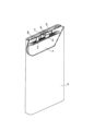
- FIG. 1 is a cross-sectional view schematically showing the structure of a positive electrode according to an embodiment of the present disclosure
- FIG. 1 is a schematic perspective view of a partially cutaway secondary battery according to an embodiment of the present disclosure
- FIG. 4 is a graph showing charge/discharge curves of the battery of Example 1.
- FIG. 4 is a graph showing charge/discharge curves of a battery of Comparative Example 1.
- FIG. 4 is a graph showing changes in capacity retention ratios of batteries of Example 1 and Comparative Examples 1 and 2 for each charge/discharge cycle under conditions of charging to an overcharged state.
- 10 is a graph showing charge/discharge curves of the battery of Example 6.
- the present disclosure encompasses a combination of matters described in two or more claims arbitrarily selected from the multiple claims described in the attached claims. In other words, as long as there is no technical contradiction, the matters described in two or more claims arbitrarily selected from the multiple claims described in the attached claims can be combined.
- a positive electrode for a secondary battery includes a positive electrode current collector and a positive electrode mixture layer provided on the surface of the positive electrode current collector.
- the positive electrode current collector contains Al and is composed of a sheet-like conductive material.
- the positive electrode current collector is, for example, aluminum foil or aluminum alloy foil.
- the positive electrode mixture layer is carried on one or both surfaces of the positive electrode current collector.
- the positive electrode mixture layer is usually a layer (including a membrane or film) composed of a positive electrode mixture.
- the positive electrode mixture contains a positive electrode active material as an essential component.
- the positive electrode mixture layer includes a first layer in contact with the positive electrode current collector and a second layer in contact with the first layer.
- the first layer and the second layer are laminated in this order on the positive electrode current collector, and the first layer is sandwiched between the positive electrode current collector and the second layer.
- the first layer includes first positive electrode active material particles having a particle size L.
- the second layer includes second positive electrode active material particles having a particle size R.
- the third positive electrode active material particles having a particle size r are present at least at the interface between the first layer and the second layer.
- the third positive electrode active material particles may be contained in the entire second layer.
- the particle size L of the first positive electrode active material particles, the particle size R of the second positive electrode active material particles, and the particle size r of the third positive electrode active material particles satisfy the relationship R>L>r.
- the particle size L, the particle size R, and the particle size r are each measured from a cross-section in the thickness direction obtained by simultaneously cutting the positive electrode mixture layer and the positive electrode current collector, as will be described later.
- the first positive electrode active material particles contain a first lithium-transition metal composite oxide.
- the ratio of Co to the metal elements other than Li contained in the first lithium-transition metal composite oxide is 2 atomic % or more.
- the first lithium-transition metal composite oxide preferably contains Ni, Co and Al.
- Such a first lithium-transition metal composite oxide has high electron conductivity and excellent adhesion to the aluminum foil that is the positive electrode current collector. Therefore, since the first layer containing the first lithium-transition metal composite oxide is in contact with the positive electrode current collector, the current collecting property is improved, and the resistance between the first layer and the positive electrode current collector can be reduced. . As a result, polarization during rapid charging is alleviated, and charging/discharging characteristics are improved.
- the first layer is also in contact with the second layer containing the second positive electrode active material particles on the opposite side of the positive electrode current collector.
- the second layer contains a second lithium-transition metal composite oxide.
- the second lithium-transition metal composite oxide does not contain Co, or the ratio of Co to metal elements other than Li contained in the second lithium-transition metal composite oxide is less than 2 atomic %.
- a layer containing such a second lithium-transition metal composite oxide has a large resistance when it is brought into direct contact with an aluminum foil that is a positive electrode current collector.
- the second layer containing the second lithium-transition metal composite oxide does not directly contact the positive electrode current collector, but is in contact with the first layer.
- the resistance between the first layer and the second layer is small, polarization is suppressed, and charge/discharge characteristics are improved.
- the particle size R of the second positive electrode active material particles is larger than the particle size L of the first positive electrode active material particles (R>L), thick conductive paths are easily formed, and the first layer and the second layer.
- the third positive electrode active material particles having a particle size r smaller than the particle size L of the first positive electrode active material particles and the particle size r of the second positive electrode active material particles R separate the first layer and the second layer. at the interface between the first positive electrode active material particles and the second positive electrode active material particles.
- the third positive electrode active material particles contain a third lithium-transition metal composite oxide.
- the third lithium transition metal composite oxide does not contain Co, or the ratio of Co to the metal elements other than Li contained in the third lithium transition metal composite oxide is 2 atoms. %.
- the third lithium transition metal composite oxide may be a composite oxide having the same composition as the second lithium transition metal oxide except that the particle size is different, or a composite oxide different from the second lithium transition metal oxide. It may be an oxide.
- the third positive electrode active material particles may be contained inside the second layer in addition to the interface between the first layer and the second layer. In that case, the third positive electrode active material particles can be arranged in the second layer so as to fill the gaps between the second positive electrode active material particles. As a result, the filling rate of the positive electrode active material particles in the positive electrode mixture layer is increased, the capacity is increased, the resistance of the second layer is further decreased, and the charge/discharge characteristics are further improved.
- the third positive electrode active material particles may not be contained inside the first layer, and the third positive electrode active material particles may not be present at the interface between the positive electrode current collector and the first layer.
- the third positive electrode active material particles do not fill the gaps between the first positive electrode active material particles in the first layer, and the electrolyte can be held in the gaps between the first positive electrode active material particles. .
- a high capacity can be maintained even during rapid charging and discharging, and rate characteristics are improved.
- the third positive electrode active material particles are not present at the interface between the positive electrode current collector and the first layer means that when the cross section of the positive electrode is observed, the surface of the positive electrode current collector and one contacting this In the space formed between the first positive electrode active material particle and the adjacent first positive electrode active material particle (which particle is also in contact with the positive electrode current collector), the third positive electrode active material particle means that there are none or at most three.
- the particle size r of the third positive electrode active material particles and the particle size L of the first positive electrode active material particles preferably satisfy the relationship of r>0.155L.
- the third positive electrode active material particles at the interface between the first layer and the second layer are the first positive electrode active material particles. Intrusion into the first layer through gaps between substance particles is suppressed. Therefore, a space capable of holding the electrolytic solution is formed in the gap between the first positive electrode active material particles in the first layer, and the rate characteristics can be improved.
- the particle size L of the first positive electrode active material particles, the particle size R of the second positive electrode active material particles, and the particle size r of the third positive electrode active material particles are respectively the positive electrode mixture layer and the positive electrode current collector.
- the cross section may be formed using a cross section polisher (CP).
- the positive electrode mixture layer may be filled with a thermosetting resin and cured.
- the diameter (equivalent circle diameter) of a circle having the same area as the cross-sectional area of the particle (the area of the particle observed in the cross section of the positive electrode mixture layer) is obtained, and the maximum equivalent circle diameter is Let the value be the maximum diameter. Observe 10 or more particles and determine the maximum diameter.
- a cross section in the thickness direction of the second layer shows the second positive electrode active material particles and the third positive electrode active material particles.
- the second positive electrode active material particles and the third positive electrode active material particles can be distinguished from the cross-sectional image, the maximum diameter of each of the second positive electrode active material particles and the third positive electrode active material particles is obtained, R and r can be determined.
- two peaks, ie, a peak due to the second positive electrode active material particles and a peak due to the third positive electrode active material particles may appear. Two peaks are separated in the equivalent circle diameter distribution, and the maximum values are obtained from the separated peak due to the second positive electrode active material particles and the separated peak due to the separated third positive electrode active material particles, and R and r are calculated. you may ask.
- the D80 diameter (particle diameter at cumulative volume of 80%) in the volume-based particle size distribution of each of the material particles and the third positive electrode active material particles may be determined as L, R, and r.
- the volume-based particle size distribution can be measured by a laser diffraction scattering method. For example, "LA-750" manufactured by HORIBA, Ltd. can be used as the measuring device.
- the particle size distribution obtained by separating and collecting the positive electrode active material particles in the second layer includes the second positive electrode active material particles and a peak due to the third positive electrode active material particles appear.
- the peak due to the second positive electrode active material particles and the peak due to the third positive electrode active material particles may be separated from the particle size distribution, the D80 diameter may be determined from each peak in the particle size distribution, and R and r may be determined.
- the particle size R of the second positive electrode active material particles may be, for example, in the range of 10 to 30 ⁇ m, or may be in the range of 10 to 25 ⁇ m.
- the particle size r of the third positive electrode active material particles may be in the range of 1 to 5 ⁇ m, for example.
- composite oxide NCM lithium-nickel-cobalt-manganese composite oxide containing Ni, Co and Mn
- NCA lithium-nickel-cobalt-aluminum composite oxides containing Ni, Co and Al
- composite oxide NCMs include LiNi 0.5 Co 0.2 Mn 0.3 O 2 and LiNi 1/3 Co 1/3 Mn 1/3 O 2 .
- the composite oxide NCA is Li ⁇ Ni 1-xy Co x Al y O 2 (where 0.95 ⁇ 1.05, 0.02 ⁇ x ⁇ 0.1, 0.02 ⁇ x+y ⁇ 1 ) may be a composite oxide represented by In the above formula, the ⁇ value, which indicates the molar ratio of lithium, is the value when discharged until the positive electrode potential reaches 2.5 V with respect to the Li counter electrode, and increases or decreases due to charging and discharging.
- lithium-nickel containing Ni and Mn - manganese composite oxide (hereinafter referred to as "composite oxide NM").
- composite oxide NM lithium-nickel containing Ni and Mn - manganese composite oxide
- the ratio of Ni and Mn to the metal elements other than Li contained in the composite oxide NM may be 98 atomic % or more.
- the composite oxide NM may be a composite oxide represented by Li ⁇ Ni 1-x Mn x O 2 (where 0.95 ⁇ 1.05 and 0 ⁇ x ⁇ 0.2).
- FIG. 1 is a cross-sectional view schematically showing the structure of the positive electrode for a secondary battery according to this embodiment.
- the positive electrode 10 includes a positive electrode current collector 11 and a positive electrode mixture layer 12 provided on the surface of the positive electrode current collector 11 .
- FIG. 1 shows a part of a cross section in the thickness direction of the positive electrode mixture layer 12 and the positive electrode current collector 11 simultaneously cut.
- the positive electrode mixture layers 12 may be formed on both main surfaces of the positive electrode current collector 11 .
- FIG. 1 shows a part of one main surface side of the positive electrode current collector 11 and a part of the positive electrode mixture layer 12 formed on the main surface, and the other main surface side of the positive electrode current collector 11. is omitted.
- the positive electrode mixture layer 12 includes a first layer 12A in contact with the positive electrode current collector 11 and a second layer 12B in contact with the first layer 12A on the side facing the positive electrode current collector 11 with the first layer interposed therebetween.
- the first layer 12A includes first positive electrode active material particles P1.
- the second layer 12B includes second positive electrode active material particles P2 and third positive electrode active material particles P3.
- the particle size L of the first positive electrode active material particles P1 is smaller than the particle size R of the second positive electrode active material particles P2 and larger than the particle size of the third positive electrode active material P3 (R>L>r). .
- the positive electrode current collector 11 is aluminum foil.
- the first positive electrode active material particles P1 are a lithium-nickel-cobalt-aluminum composite oxide (composite oxide NCA), and a part of the first positive electrode active material particles P1 is a positive electrode current collector. It is in contact with the positive electrode current collector 11 so as to be embedded in the aluminum foil 11 . As a result, the first positive electrode active material particles P1 come into surface contact with the positive electrode current collector 11, and the resistance between the positive electrode current collector 11 and the first layer 12A decreases.
- composite oxide NCA lithium-nickel-cobalt-aluminum composite oxide
- the third positive electrode active material particles P3 are present in the gaps between .
- the second positive electrode active material particles P2 are in direct contact with the first positive electrode active material particles P1, and are in contact with the first positive electrode active material particles P1 via the third positive electrode active material particles P3.
- the third positive electrode active material particles P3 are not interposed in the gaps between the first positive electrode active material particles P1 in the first layer.
- the gaps between the first positive electrode active material particles P1 are filled with the electrolytic solution. As a result, rate characteristics can be improved.
- the three first positive electrode active material particles P1 forming a triangular lattice in the plane form
- the second positive electrode active material particles P2 and the third positive electrode active material particles P3 here are lithium-nickel-manganese composite oxides (composite oxides NM).
- composite oxides NM lithium-nickel-manganese composite oxides
- the filling density of the positive electrode active material in the second layer can be increased. can increase the capacity.
- FIG. 1 shows the positive electrode mixture layer 12 having a two-layer structure of the first layer 12A and the second layer 12B, another positive electrode active material layer exists on the second layer 12B. good too.
- a secondary battery has, for example, the positive electrode, a separator, a negative electrode facing the positive electrode with the separator interposed therebetween, and an electrolytic solution.
- the positive electrode includes a positive electrode current collector and a positive electrode mixture layer formed on the surface of the positive electrode current collector and containing a positive electrode active material.
- the positive electrode active material layer contains a positive electrode active material as an essential component, and may contain a binder, a conductive agent, and the like as optional components. Known materials can be used as the binder, conductive agent, and thickener.
- the positive electrode mixture layer has a laminated structure of at least two layers, the first layer in contact with the positive electrode current collector and the second layer in contact with the first layer.
- the thickness T1 of the first layer is, for example, 3 to 30 ⁇ m.
- the thickness T2 of the second layer is, for example, 10-150 ⁇ m.
- the ratio of the thickness T1 of the first layer to the thickness T2 of the second layer: T1/T2 is, for example, 0.1 to 1.0.
- the first layer contains the first positive electrode active material particles having the particle size L as described above.
- the second layer includes second positive electrode active material particles having a particle size R.
- Third positive electrode active material particles having a particle size r are present at least at the interface between the first layer and the second layer.
- the third positive electrode active material particles may be dispersed in the second layer together with the second positive electrode active material particles.
- the first layer is formed by, for example, a process of applying a first positive electrode slurry in which a first positive electrode mixture containing first positive electrode active material particles, a binder, etc. is dispersed in a dispersion medium to the surface of the positive electrode current collector. It can be formed by a method having For the second layer, for example, a second positive electrode slurry in which a second positive electrode mixture containing second positive electrode active material particles, third positive electrode active material particles, a binder, etc. is dispersed in a dispersion medium is applied to the first positive electrode slurry. It can be formed by a method including a process of coating the surface of the positive electrode slurry. The laminated coating film after drying may be rolled if necessary. The first positive electrode slurry and the second positive electrode slurry may be simultaneously applied to the surface of the positive electrode current collector using a two-fluid nozzle.
- the second positive electrode active material particles account for the total of the second positive electrode active material particles and the third positive electrode active material particles.
- the proportion may be from 50% to 90% or from 65% to 85% by mass.
- a lithium-transition metal composite oxide containing lithium and Ni and having a layered rock salt crystal structure can be used as the first to third positive electrode active material particles.
- the metal element other than lithium and the ratio of the metal element in the lithium-transition metal composite oxide can be changed.
- Ni-containing lithium-transition metal composite oxides are advantageous for increasing capacity and reducing costs. From the viewpoint of obtaining a high capacity, it is desirable that the proportion of Ni in the metal elements other than Li contained in the lithium-transition metal composite oxide is 80 atomic % or more.
- the ratio of Ni to the metal elements other than Li may be 85 atomic % or more, or 90 atomic % or more.
- the ratio of Ni to the metal elements other than Li is desirably 95 atomic % or less, for example. When limiting the range, these upper and lower limits can be combined arbitrarily.
- the lithium transition metal composite oxide may contain Co, Mn and/or Al. Co, Mn and Al contribute to stabilization of the crystal structure of the composite oxide with a high Ni content. However, from the viewpoint of manufacturing cost reduction, it is desirable that the Co content is as low as possible. A composite oxide with a low Co content or no Co may contain Mn and Al. From the viewpoint of manufacturing cost reduction, it is desirable to limit the proportion of Co to metal elements other than Li in the lithium-transition metal composite oxide to less than 2 atomic %.
- the lithium transition metal composite oxide may be represented, for example, by the general formula: Li ⁇ Ni 1-x1-x2-yz Co x1 Mn x2 Al y Me z O 2+ ⁇ .
- the general formula is 0.95 ⁇ 1.05, 0 ⁇ x1 ⁇ 0.1, 0 ⁇ x2 ⁇ 0.5, 0 ⁇ y ⁇ 0.1, 0 ⁇ z ⁇ 0.1, 0. 5 ⁇ 1-x1-x2-yz and -0.05 ⁇ 0.05
- Me is an element other than Li, Ni, Mn, Al, Co and oxygen.
- the ⁇ value which indicates the molar ratio of lithium, is the value when the positive electrode potential is charged to 2.5 V based on the Li counter electrode, and increases or decreases due to charging and discharging.
- Me includes Nb, Zr, B, Mg, Fe, Cu, Zn, Sn, Na, K, Ba, Sr, Ca, W, Mo, Si , Ti, Fe and Cr.
- the first lithium-transition metal composite oxide used for the first positive electrode active material particles is Li ⁇ Ni 1-x-y Co x Al y O 2 (where 0.
- a lithium-nickel-cobalt-aluminum composite oxide (composite oxide NCA) represented by 02 ⁇ x ⁇ 0.1, 0.02 ⁇ x+y ⁇ 1) can be used.
- the composite oxide NCA contains a relatively large amount of Co, it has high electron conductivity and good adhesion to the positive electrode current collector, so that the contact resistance can be reduced.
- by reducing the ratio of the thickness of the first layer to the thickness of the positive electrode mixture layer it is possible to minimize the increase in manufacturing cost due to the inclusion of Co.
- the production cost can be reduced by limiting the ratio of Co to the metal elements other than Li to less than 2 atomic %.
- the lithium-transition metal composite oxides as the second lithium-transition metal composite oxide used for the second positive electrode active material particles or the third lithium-transition metal composite oxide used for the third positive electrode active material particles, A lithium-manganese composite oxide (composite oxide NM) represented by Li ⁇ Ni 1-x Mn x (where 0 ⁇ x ⁇ 0.2) can be used.
- composite oxide NM composite oxide represented by Li ⁇ Ni 1-x Mn x (where 0 ⁇ x ⁇ 0.2)
- the shape and thickness of the positive electrode current collector may be, for example, 5 ⁇ m or more and 20 ⁇ m or less.
- materials for the positive electrode current collector include stainless steel, aluminum, aluminum alloys, and titanium.
- the negative electrode includes, for example, a negative electrode current collector and a negative electrode active material layer formed on the surface of the negative electrode current collector.
- the negative electrode active material layer can be formed, for example, by applying a negative electrode slurry in which a negative electrode mixture containing a negative electrode active material, a binder and the like is dispersed in a dispersion medium on the surface of the negative electrode current collector and drying the slurry. The dried coating film may be rolled if necessary. That is, the negative electrode active material may be the negative electrode mixture layer. Alternatively, a lithium metal foil or a lithium alloy foil may be attached to the negative electrode current collector as the negative electrode active material layer.
- the negative electrode active material layer may be formed on one surface of the negative electrode current collector, or may be formed on both surfaces.
- the negative electrode active material layer contains the negative electrode active material as an essential component, and may contain a binder, a conductive agent, a thickener, etc. as optional components. Known materials can be used as the binder, conductive agent, and thickener.
- Negative electrode active materials include materials that electrochemically absorb and release lithium ions, lithium metal, and lithium alloys. Carbon materials, alloy materials, and the like are used as materials that electrochemically occlude and release lithium ions. Examples of carbon materials include graphite, graphitizable carbon (soft carbon), and non-graphitizable carbon (hard carbon). Among them, graphite is preferable because it has excellent charging/discharging stability and low irreversible capacity. Examples of alloy materials include those containing at least one metal capable of forming an alloy with lithium, such as silicon, tin, silicon alloys, tin alloys, and silicon compounds. Silicon oxide, tin oxide, or the like in which these are combined with oxygen may also be used.
- a lithium ion conductive phase and a silicon composite material in which silicon particles are dispersed in the lithium ion conductive phase can be used.
- the lithium ion conductive phase for example, a silicon oxide phase, a silicate phase, a carbon phase, or the like can be used.
- a major component (eg, 95-100% by weight) of the silicon oxide phase can be silicon dioxide.
- a composite material composed of a silicate phase and silicon particles dispersed in the silicate phase is preferable in terms of high capacity and low irreversible capacity.
- a silicate phase containing lithium hereinafter also referred to as a lithium silicate phase
- a silicate phase containing lithium is preferable because of its small irreversible capacity and high initial charge/discharge efficiency.
- the lithium silicate phase may be an oxide phase containing lithium (Li), silicon (Si), and oxygen (O), and may contain other elements.
- the atomic ratio of O to Si: O/Si in the lithium silicate phase is greater than 2 and less than 4, for example.
- O/Si is greater than 2 and less than 3.
- the atomic ratio of Li to Si in the lithium silicate phase: Li/Si is greater than 0 and less than 4, for example.
- Elements other than Li, Si and O that can be contained in the lithium silicate phase include, for example, iron (Fe), chromium (Cr), nickel (Ni), manganese (Mn), copper (Cu), molybdenum (Mo), Examples include zinc (Zn) and aluminum (Al).
- the carbon phase can be composed of, for example, amorphous carbon with low crystallinity (that is, amorphous carbon).
- Amorphous carbon may be, for example, hard carbon, soft carbon, or otherwise.
- a non-porous conductive substrate metal foil, etc.
- a porous conductive substrate meh body, net body, punching sheet, etc.
- materials for the negative electrode current collector include stainless steel, nickel, nickel alloys, copper, and copper alloys.
- the electrolyte contains a solvent and a solute dissolved in the solvent.
- a solute is an electrolyte salt that ionically dissociates in the electrolyte.
- Solutes can include, for example, lithium salts.
- Components of electrolytes other than solvents and solutes are additives.
- the electrolyte may contain various additives.
- aqueous solvent or a non-aqueous solvent is used as the solvent.
- non-aqueous solvents include cyclic carbonates, chain carbonates, cyclic carboxylates, chain carboxylates, and the like.
- Cyclic carbonates include propylene carbonate (PC), ethylene carbonate (EC), vinylene carbonate (VC) and the like.
- Chain carbonates include diethyl carbonate (DEC), ethyl methyl carbonate (EMC), dimethyl carbonate (DMC) and the like.
- cyclic carboxylic acid esters include ⁇ -butyrolactone (GBL) and ⁇ -valerolactone (GVL).
- Chain carboxylic acid esters include methyl acetate, ethyl acetate, propyl acetate, methyl propionate (MP), ethyl propionate (EP) and the like.
- the non-aqueous solvent may be used singly or in combination of two or more.
- lithium salts include lithium salts of chlorine-containing acids ( LiClO4 , LiAlCl4 , LiB10Cl10 , etc.), lithium salts of fluorine-containing acids ( LiPF6 , LiPF2O2 , LiBF4 , LiSbF6 , LiAsF6 , LiCF3SO3 , LiCF3CO2 , etc.), lithium salts of fluorine-containing acid imides ( LiN( FSO2 ) 2 , LiN( CF3SO2 ) 2 , LiN( CF3SO2 ) ( C4F9SO 2 ) , LiN ( C2F5SO2 ) 2, etc.), lithium halides (LiCl, LiBr, LiI, etc.) can be used. Lithium salts may be used singly or in combination of two or more.
- the concentration of the lithium salt in the electrolytic solution may be 1 mol/liter or more and 2 mol/liter or less, or may be 1 mol/liter or more and 1.5 mol/liter or less.
- the lithium salt concentration is not limited to the above.
- Separator It is desirable to interpose a separator between the positive electrode and the negative electrode.
- the separator has high ion permeability and moderate mechanical strength and insulation.
- a microporous thin film, a woven fabric, a nonwoven fabric, or the like can be used as the separator.
- Polyolefins such as polypropylene and polyethylene are preferable as the material of the separator.
- an electrode group in which a positive electrode and a negative electrode are wound with a separator interposed therebetween, is housed in an outer package together with an electrolytic solution.
- an electrode group in which a positive electrode and a negative electrode are wound with a separator interposed therebetween
- an electrolytic solution it is not limited to this, and other forms of electrode groups may be applied.
- a laminated electrode group in which a positive electrode and a negative electrode are laminated with a separator interposed therebetween may be used.
- the shape of the battery is also not limited, and may be, for example, cylindrical, square, coin, button, laminate, or the like.
- the battery includes a prismatic battery case 4 with a bottom, and an electrode group 1 and an electrolytic solution (not shown) housed in the battery case 4 .
- the electrode group 1 has a long strip-shaped negative electrode, a long strip-shaped positive electrode, and a separator interposed therebetween.
- the negative electrode current collector of the negative electrode is electrically connected to a negative electrode terminal 6 provided on a sealing plate 5 via a negative electrode lead 3 .
- the negative electrode terminal 6 is insulated from the sealing plate 5 by a resin gasket 7 .
- the positive current collector of the positive electrode is electrically connected to the rear surface of the sealing plate 5 via the positive lead 2 . That is, the positive electrode is electrically connected to the battery case 4 which also serves as a positive electrode terminal.
- the peripheral edge of the sealing plate 5 is fitted into the open end of the battery case 4, and the fitted portion is laser-welded.
- the sealing plate 5 has an injection hole for a non-aqueous electrolyte, which is closed by a sealing plug 8 after the
- Example 1 [Preparation of positive electrode] A lithium-cobalt-aluminum composite oxide (LiNi 0.91 Co 0.05 Al 0.04 O 2 ) was prepared as the first positive electrode active material particles.
- Lithium-nickel-manganese composite oxides (LiNi 0.8 Mn 0.2 O 2 ) having different average particle diameters were prepared as the second positive electrode active material particles and the third positive electrode active material particles.
- the particle diameters R and r of the second and third positive electrode active material particles measured as the D80 diameter in the volume-based particle size distribution by a laser diffraction scattering method were 15 ⁇ m and 1 ⁇ m, respectively.
- a first positive electrode slurry was prepared.
- the first positive electrode slurry is applied to the surface of an aluminum foil that is a positive electrode current collector, the coating is dried, and then the second positive electrode slurry is applied so as to cover the coating of the first positive electrode slurry.
- the film was dried and rolled to form a 100 ⁇ m thick positive electrode mixture layer on an aluminum foil.
- a cross section in the thickness direction is formed by simultaneously cutting the positive electrode mixture layer and the positive electrode current collector, and an SEM image of the cross section is taken.
- the maximum diameter (maximum equivalent circle diameter) of the second and third positive electrode active material particles was obtained.
- L, R, and r determined as the maximum value of the equivalent circle diameter approximately matched L, R, and r, respectively, determined as the D80 diameter in the volume-based particle size distribution.
- a positive electrode for evaluation was obtained by cutting the positive electrode into a predetermined shape.
- the positive electrode was provided with a 20 mm ⁇ 20 mm region functioning as a positive electrode and a 5 mm ⁇ 5 mm connecting region with a tab lead. After that, the positive electrode material mixture layer formed on the connection region was scraped off to expose the positive electrode current collector. After that, the exposed portion of the positive electrode current collector was connected to the positive electrode tab lead, and a predetermined region of the outer circumference of the positive electrode tab lead was covered with an insulating tab film.
- a negative electrode was prepared by attaching a lithium metal foil (thickness: 300 ⁇ m) to one side of an electrolytic copper foil that was a negative electrode current collector.
- a negative electrode was cut into the same shape as the positive electrode to obtain a negative electrode for evaluation.
- the lithium metal foil formed on the connection region formed in the same manner as the positive electrode was peeled off to expose the negative electrode current collector. After that, the exposed portion of the negative electrode current collector was connected to the negative electrode tab lead in the same manner as the positive electrode, and a predetermined region of the outer periphery of the negative electrode tab lead was covered with an insulating tab film.
- LiPF6 was added as a lithium salt to a mixed solvent containing ethylene carbonate (EC), ethyl methyl carbonate (EMC) and dimethyl carbonate (DMC) at a volume ratio of 20:5:75 to prepare an electrolytic solution.
- EC ethylene carbonate
- EMC ethyl methyl carbonate
- DMC dimethyl carbonate
- a battery for evaluation was produced using the positive electrode and the negative electrode for evaluation.
- the positive electrode and the negative electrode were opposed to each other with the separator interposed therebetween so that the positive electrode mixture layer and the negative electrode mixture layer overlapped to obtain an electrode plate assembly.
- an Al laminate film (thickness: 100 ⁇ m) cut into a rectangle of 60 ⁇ 90 mm was folded in half, and the end of the long side of 60 mm was heat-sealed at 230° C. to form a cylinder of 60 ⁇ 45 mm.
- the produced electrode plate group was placed in a cylinder, and heat sealing was performed at 230° C. with the end surface of the Al laminate film aligned with the insulating tab film of each tab lead.
- 0.3 cm 3 of a non-aqueous electrolyte is injected from the short side of the Al laminate film that is not heat-sealed, and after the injection, it is left to stand under a reduced pressure of 0.06 MPa for 5 minutes.
- the layers were impregnated with electrolyte.
- the end face of the Al laminate film on the injected side was heat-sealed at 230° C. to prepare battery A1 for evaluation.
- the evaluation cell was produced in a dry environment with a dew point of ⁇ 50° C. or less.
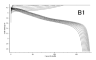
- Example 1 In the preparation of the positive electrode, only the second positive electrode slurry of Example 1 was applied to the surface of the aluminum foil as the positive electrode current collector, and in the same manner as in Example 1, it had the same theoretical capacity as in Example 1 and had a thickness of 100 ⁇ m. A positive electrode having a positive electrode mixture layer was obtained. A battery B1 for evaluation was produced in the same manner as in Example 1 using this positive electrode.
- a positive electrode slurry was prepared by mixing 98 parts by mass of a positive electrode active material mixed at a mass ratio, 1 part by mass of acetylene black (AB), 1 part by mass of polyvinylidene fluoride (PVDF), and an appropriate amount of NMP.
- a positive electrode having a positive electrode mixture layer with a thickness of 100 ⁇ m was obtained in the same manner except that only the positive electrode slurry was applied to the surface of an aluminum foil as a positive electrode current collector.
- the contents of the first to third positive electrode active material particles in the positive electrode mixture layer are the same as those of the positive electrode of Example 1.
- the positive electrode mixture layer does not have the first layer and the second layer, and the first to third positive electrode active material particles are dispersed in the positive electrode mixture layer.
- a rest period between charging and discharging was set to 20 minutes, and charging and discharging were repeated 10 cycles under the above charging and discharging conditions in an environment of 25°C.
- the discharge capacity Cn was obtained with respect to the charge capacity C0 in the first cycle, and Cn/ C0 ⁇ 100 was evaluated as the capacity retention rate.
- FIG. 3A shows the measurement results of the charge-discharge curve of the battery A1.
- FIG. 3B shows the measurement results of the charge/discharge curve of battery B1.
- the voltage during charging tends to increase and the discharge capacity tends to decrease as the charge/discharge cycle is repeated.
- FIG. 3A compared with FIG. 3B, the increase in charge voltage due to repeated charge/discharge cycles is suppressed, and the polarization is reduced.
- a decrease in discharge capacity due to repeated charge-discharge cycles is suppressed.
- FIG. 4 shows changes in the capacity retention rate of batteries A1, B1 and B2 for each charge/discharge cycle.
- charging is performed at a high voltage of 4.5 V until an overcharged state is reached in the charging/discharging cycle, and the environment is such that Mn in the lithium-nickel-manganese composite oxide is easily eluted.
- the decrease in discharge capacity due to repeated charge-discharge cycles is suppressed compared to batteries B1 and B2.
- Example 2 to 6 Comparative Example 3>
- the particle sizes of the first to third positive electrode active material particles were changed as shown in Table 1.
- Batteries A2 to A6 and B3 for evaluation were produced in the same manner as in Example 1, and the discharge rate characteristics were evaluated by the method described below.
- Table 1 shows the evaluation results of the discharge rate characteristics of the batteries A1 to A6 and B3 together with the particle sizes of the first to third positive electrode active material particles. Batteries A1 to A5 satisfying R>L>r and r>0.155L were able to maintain high discharge rate characteristics.
- Fig. 5 shows the charge/discharge curve of Battery A6. Since the battery A6 satisfies R>L>r, it is inferior to the battery A1, but the increase in the charge voltage due to the repetition of the charge-discharge cycle is suppressed, and the decrease in the discharge capacity due to the repetition of the charge-discharge cycle is suppressed. Suppressed. However, since r>0.155L was not satisfied, the discharge rate characteristics were lower than those of Batteries A1 to A5.
- a secondary battery according to the present disclosure it is possible to provide a secondary battery that has a high capacity and is advantageous in improving charge/discharge characteristics.
- a secondary battery according to the present disclosure is useful as a main power source for mobile communication devices, electric vehicles, hybrid vehicles, portable electronic devices, and the like.
Abstract
This positive electrode for secondary batteries is provided with a positive electrode collector 11 and a positive electrode mixture layer that is arranged on a surface of the positive electrode collector; and the positive electrode mixture layer comprises a first layer 12A that is in contact with the positive electrode collector and a second layer 12B that is in contact with the first layer. The first layer 12A contains first positive electrode active material particles that have a particle diameter L. The second layer 12B contains second positive electrode active material particles that have a particle diameter R. Third positive electrode active material particles that have a particle diameter r are contained at least in the interface between the first layer and the second layer. The first positive electrode active material particles contain a lithium transition metal composite oxide in which the proportion of Co in the metal elements other than Li is 2% by atom or more. The second and third positive electrode active material particles contain a lithium transition metal composite oxide in which Co is not contained or alternatively, the proportion of Co in the metal elements other than Li is less than 2% by atom. The particle diameters of the first to third positive electrode active material particles satisfy the relational expression R > L > r.
Description
本開示は、二次電池用正極および二次電池に関する。
The present disclosure relates to positive electrodes for secondary batteries and secondary batteries.
二次電池、特にリチウムイオン二次電池は、高出力かつ高エネルギー密度を有するため、小型民生用途、電力貯蔵装置および電気自動車の電源として期待されている。
Secondary batteries, especially lithium-ion secondary batteries, have high output and high energy density, so they are expected to be used as power sources for small consumer applications, power storage devices, and electric vehicles.
特許文献1は、正極活物質としてリチウム遷移金属複合酸化物が含まれる正極合材層と集電箔を備えたリチウム二次電池用正極において、正極合剤層を、α-NaFeO2構造を有し、遷移金属(Me)がCo、Ni及びMnを含み、遷移金属に対するリチウム(Li)のモル比Li/Meが1.2より大きく、モル比Mn/MeがMn/Me≧0.5であるリチウム過剰型の遷移金属複合酸化物を含む層と、集電箔に接し、且つ遷移金属(Me')がCo、Ni及びMnから選択される1種以上を含み、遷移金属に対するリチウム(Li)のモル比Li/Me'が1.2 以下であり、モル比Mn/Me'が0≦Mn/Me'≦0.4であるリチウム遷移金属複合酸化物を含む層と、の二層以上とすることを提案している。
Patent Document 1 discloses a positive electrode for a lithium secondary battery comprising a positive electrode mixture layer containing a lithium transition metal composite oxide as a positive electrode active material and a current collector foil, wherein the positive electrode mixture layer has an α-NaFeO 2 structure. and the transition metal (Me) contains Co, Ni and Mn, the molar ratio Li/Me of lithium (Li) to the transition metal is greater than 1.2, and the molar ratio Mn/Me is Mn/Me≧0.5 A layer containing a lithium-excess transition metal composite oxide, in contact with the current collector foil, and containing one or more transition metals (Me') selected from Co, Ni and Mn, and lithium (Li ) and a layer containing a lithium-transition metal composite oxide having a molar ratio Li/Me' of 1.2 or less and a molar ratio Mn/Me' of 0 ≤ Mn/Me' ≤ 0.4. It is proposed that
近年、生産コストを抑制する観点から、正極活物質としてコバルト(Co)の含有比率が小さいか、あるいはコバルトを含まないコバルトフリーのリチウム遷移金属複合酸化物の使用が望まれている。なかでも、NiとMnとを含むリチウム-ニッケル-マンガン複合酸化物LiNi1-xMnxO2(x≦0.2)は、充放電容量が大きいことから有望視されている。
In recent years, from the viewpoint of suppressing production costs, the use of cobalt-free lithium-transition metal composite oxides with a low cobalt (Co) content or containing no cobalt as a positive electrode active material has been desired. Among them, a lithium-nickel-manganese composite oxide LiNi 1-x Mn x O 2 (x≦0.2) containing Ni and Mn is considered promising because of its large charge/discharge capacity.
しかしながら、上記のリチウム-ニッケル-マンガン複合酸化物は、従来より用いられているコバルトを含むリチウム遷移金属複合酸化物(例えば、リチウム-ニッケル-コバルト-アルミニウム複合酸化物)と比べて電子伝導性が低い。また、表面に不純物層が存在すると集電性が低下する。加えて、集電体として用いられているアルミニウム箔との接触抵抗も大きい。これらの理由により、リチウム-ニッケル-マンガン複合酸化物は、抵抗が大きく、分極が大きくなり易い。加えて、充放電サイクルを繰り返すに伴い、活物質の膨張収縮によりアルミニウム箔との間に隙間が生じ、抵抗が大きくなり易い。結果、リチウム-ニッケル-マンガン複合酸化物を正極活物質に用いる二次電池は、充放電特性が低下し易い。
However, the above-mentioned lithium-nickel-manganese composite oxide has lower electron conductivity than conventionally used lithium-transition metal composite oxides containing cobalt (for example, lithium-nickel-cobalt-aluminum composite oxides). low. In addition, when an impurity layer is present on the surface, the current collecting property is lowered. In addition, the contact resistance with aluminum foil used as a current collector is also large. For these reasons, lithium-nickel-manganese composite oxides tend to have high resistance and large polarization. In addition, as the charge/discharge cycle is repeated, the expansion and contraction of the active material creates a gap between the active material and the aluminum foil, which tends to increase the resistance. As a result, a secondary battery using a lithium-nickel-manganese composite oxide as a positive electrode active material tends to deteriorate in charge-discharge characteristics.
本開示の一側面は、正極集電体と、前記正極集電体の表面に設けられた正極合剤層と、を備え、前記正極集電体は、Alを含み、前記正極合剤層は、前記正極集電体と接する第1層と、前記第1層と接する第2層と、を備え、前記第1層は、粒径Lの第1の正極活物質粒子を含み、前記第2層は、粒径Rの第2の正極活物質粒子を含み、少なくとも前記第1層と前記第2層の界面に、粒径rの第3の正極活物質粒子を含み、前記第1の正極活物質粒子は、第1リチウム遷移金属複合酸化物を含み、前記第1リチウム遷移金属複合酸化物に含まれるLi以外の金属元素に占めるCoの割合が2原子%以上であり、前記第2の正極活物質粒子は、第2リチウム遷移金属複合酸化物を含み、前記第2リチウム遷移金属複合酸化物は、Coを含まないか、前記第2リチウム遷移金属複合酸化物に含まれるLi以外の金属元素に占めるCoの割合が2原子%未満であり、前記第3の正極活物質粒子は、第3リチウム遷移金属複合酸化物を含み、前記第3リチウム遷移金属複合酸化物は、Coを含まないか、前記第3リチウム遷移金属複合酸化物に含まれるLi以外の金属元素に占めるCoの割合が2原子%未満であり、R>L>rを満たす、二次電池用正極に関する。
One aspect of the present disclosure includes a positive electrode current collector and a positive electrode mixture layer provided on the surface of the positive electrode current collector, the positive electrode current collector contains Al, and the positive electrode mixture layer includes , a first layer in contact with the positive electrode current collector, and a second layer in contact with the first layer, wherein the first layer includes first positive electrode active material particles having a particle size L, and the second The layer contains second positive electrode active material particles with a particle size R, contains third positive electrode active material particles with a particle size r at least at the interface between the first layer and the second layer, and the first positive electrode The active material particles contain a first lithium-transition metal composite oxide, the proportion of Co in metal elements other than Li contained in the first lithium-transition metal composite oxide is 2 atomic % or more, and the second The positive electrode active material particles contain a second lithium-transition metal composite oxide, and the second lithium-transition metal composite oxide does not contain Co or contains a metal other than Li contained in the second lithium-transition metal composite oxide. The proportion of Co in the elements is less than 2 atomic %, the third positive electrode active material particles contain a third lithium-transition metal composite oxide, and the third lithium-transition metal composite oxide does not contain Co Alternatively, the present invention relates to a positive electrode for a secondary battery, wherein the ratio of Co to the metal elements other than Li contained in the third lithium-transition metal composite oxide is less than 2 atomic %, and R>L>r is satisfied.
本開示の他の側面は、上記二次電池用正極と、セパレータと、前記セパレータを介して前記正極と対向する負極と、電解液と、を有する、二次電池に関する。
Another aspect of the present disclosure relates to a secondary battery including the positive electrode for a secondary battery, a separator, a negative electrode facing the positive electrode via the separator, and an electrolytic solution.
本開示によれば、高容量であり、充放電特性の向上に有利な二次電池を実現できる。
According to the present disclosure, it is possible to realize a secondary battery that has a high capacity and is advantageous in improving charge/discharge characteristics.
本発明の新規な特徴を添付の請求の範囲に記述するが、本発明は、構成および内容の両方に関し、本発明の他の目的および特徴と併せ、図面を照合した以下の詳細な説明によりさらによく理解されるであろう。
While the novel features of the present invention are set forth in the appended claims, the present invention, both as to construction and content, together with other objects and features of the present invention, will be further developed by the following detailed description in conjunction with the drawings. will be well understood.
以下、本開示の実施形態について例を挙げて説明するが、本開示は以下で説明する例に限定されない。以下の説明では、具体的な数値、材料等を例示する場合があるが、本開示の効果が得られる限り、他の数値、材料等を適用してもよい。この明細書において、「数値A~数値B」という記載は、数値Aおよび数値Bを含み、「数値A以上で数値B以下」と読み替えることが可能である。以下の説明において、特定の物性や条件などに関する数値の下限と上限とを例示した場合、下限が上限以上とならない限り、例示した下限のいずれかと例示した上限のいずれかを任意に組み合わせることができる。複数の材料が例示される場合、その中から1種を選択して単独で用いてもよく、2種以上を組み合わせて用いてもよい。
Hereinafter, embodiments of the present disclosure will be described with examples, but the present disclosure is not limited to the examples described below. In the following description, specific numerical values, materials, etc. may be exemplified, but other numerical values, materials, etc. may be applied as long as the effects of the present disclosure can be obtained. In this specification, the description "numerical value A to numerical value B" includes numerical value A and numerical value B, and can be read as "numerical value A or more and numerical value B or less". In the following description, when lower and upper limits of numerical values relating to specific physical properties, conditions, etc. are exemplified, any of the illustrated lower limits and any of the illustrated upper limits can be arbitrarily combined as long as the lower limit is not greater than or equal to the upper limit. . When a plurality of materials are exemplified, one of them may be selected and used alone, or two or more may be used in combination.
また、本開示は、添付の特許請求の範囲に記載の複数の請求項から任意に選択される2つ以上の請求項に記載の事項の組み合わせを包含する。つまり、技術的な矛盾が生じない限り、添付の特許請求の範囲に記載の複数の請求項から任意に選択される2つ以上の請求項に記載の事項を組み合わせることができる。
In addition, the present disclosure encompasses a combination of matters described in two or more claims arbitrarily selected from the multiple claims described in the attached claims. In other words, as long as there is no technical contradiction, the matters described in two or more claims arbitrarily selected from the multiple claims described in the attached claims can be combined.
本開示の実施形態に係る二次電池用正極は、正極集電体と、正極集電体の表面に設けられた正極合剤層とを備える。正極集電体は、Alを含み、シート状の導電性材料で構成される。正極集電体は、例えば、アルミニウム箔またはアルミニウム合金箔である。正極合剤層は、正極集電体の一方または両方の表面に担持されている。正極合剤層は、通常、正極合剤で構成された層(膜もしくはフィルムを含む。)である。正極合剤は、正極活物質を必須成分として含む。
A positive electrode for a secondary battery according to an embodiment of the present disclosure includes a positive electrode current collector and a positive electrode mixture layer provided on the surface of the positive electrode current collector. The positive electrode current collector contains Al and is composed of a sheet-like conductive material. The positive electrode current collector is, for example, aluminum foil or aluminum alloy foil. The positive electrode mixture layer is carried on one or both surfaces of the positive electrode current collector. The positive electrode mixture layer is usually a layer (including a membrane or film) composed of a positive electrode mixture. The positive electrode mixture contains a positive electrode active material as an essential component.
正極合剤層は、正極集電体と接する第1層と、第1層と接する第2層と、を備える。換言すると、正極集電体上に、第1層、および第2層が、この順で積層されており、正極集電体と第2層とで第1層が挟まれている。第1層は、粒径Lの第1の正極活物質粒子を含む。第2層は、粒径Rの第2の正極活物質粒子を含む。また、少なくとも第1層と第2層の界面に、粒径rの第3の正極活物質粒子が存在している。第3の正極活物質粒子は、第2層の全体に含まれていてもよい。
The positive electrode mixture layer includes a first layer in contact with the positive electrode current collector and a second layer in contact with the first layer. In other words, the first layer and the second layer are laminated in this order on the positive electrode current collector, and the first layer is sandwiched between the positive electrode current collector and the second layer. The first layer includes first positive electrode active material particles having a particle size L. The second layer includes second positive electrode active material particles having a particle size R. Moreover, the third positive electrode active material particles having a particle size r are present at least at the interface between the first layer and the second layer. The third positive electrode active material particles may be contained in the entire second layer.
第1の正極活物質粒子の粒径L、第2の正極活物質粒子の粒径R、および、第3の正極活物質粒子の粒径rは、R>L>rの関係を満たしている。ここで、粒径L、粒径R、および粒径rは、それぞれ、後述するように、正極合剤層と正極集電体とを同時に切断した厚さ方向の断面などから測定される。
The particle size L of the first positive electrode active material particles, the particle size R of the second positive electrode active material particles, and the particle size r of the third positive electrode active material particles satisfy the relationship R>L>r. . Here, the particle size L, the particle size R, and the particle size r are each measured from a cross-section in the thickness direction obtained by simultaneously cutting the positive electrode mixture layer and the positive electrode current collector, as will be described later.
第1の正極活物質粒子は、第1リチウム遷移金属複合酸化物を含む。第1リチウム遷移金属複合酸化物に含まれるLi以外の金属元素に占めるCoの割合は2原子%以上である。第1リチウム遷移金属複合酸化物は、Ni、CoおよびAlを含むことが好ましい。このような第1リチウム遷移金属複合酸化物は、電子伝導性が高く、また正極集電体であるアルミニウム箔との密着性に優れている。よって、第1リチウム遷移金属複合酸化物を含む第1層が正極集電体と接していることで、集電性が向上し、第1層と正極集電体との間の抵抗を小さくできる。これにより、急速充電での分極が緩和され、充放電特性が向上する。
The first positive electrode active material particles contain a first lithium-transition metal composite oxide. The ratio of Co to the metal elements other than Li contained in the first lithium-transition metal composite oxide is 2 atomic % or more. The first lithium-transition metal composite oxide preferably contains Ni, Co and Al. Such a first lithium-transition metal composite oxide has high electron conductivity and excellent adhesion to the aluminum foil that is the positive electrode current collector. Therefore, since the first layer containing the first lithium-transition metal composite oxide is in contact with the positive electrode current collector, the current collecting property is improved, and the resistance between the first layer and the positive electrode current collector can be reduced. . As a result, polarization during rapid charging is alleviated, and charging/discharging characteristics are improved.
一方、第1層は、正極集電体の反対側において、第2正極活物質粒子を含む第2層とも接している。第2層は、第2リチウム遷移金属複合酸化物を含む。第2リチウム遷移金属複合酸化物は、Coを含まないか、第2リチウム遷移金属複合酸化物に含まれるLi以外の金属元素に占めるCoの割合が2原子%未満である。このような第2リチウム遷移金属複合酸化物を含む層は、正極集電体であるアルミニウム箔と直接接触させる場合、抵抗が大きい。しかしながら、本実施形態に係る二次電池用正極によれば、第2リチウム遷移金属複合酸化物を含む第2層は、正極集電体と直接接触せず、第1層と接している。また、第1層と第2層との間の抵抗も小さく、分極が抑制され、充放電特性が向上する。
On the other hand, the first layer is also in contact with the second layer containing the second positive electrode active material particles on the opposite side of the positive electrode current collector. The second layer contains a second lithium-transition metal composite oxide. The second lithium-transition metal composite oxide does not contain Co, or the ratio of Co to metal elements other than Li contained in the second lithium-transition metal composite oxide is less than 2 atomic %. A layer containing such a second lithium-transition metal composite oxide has a large resistance when it is brought into direct contact with an aluminum foil that is a positive electrode current collector. However, according to the positive electrode for a secondary battery according to this embodiment, the second layer containing the second lithium-transition metal composite oxide does not directly contact the positive electrode current collector, but is in contact with the first layer. In addition, the resistance between the first layer and the second layer is small, polarization is suppressed, and charge/discharge characteristics are improved.
第1層と第2層の界面では、第1の正極活物質粒子の少なくとも一部は、第2の正極活物質粒子の間の隙間(凹部)に嵌まり込み、第2の正極活物質粒子の表面の不純物層などを破壊するようにして第2の正極活物粒子と接触する。これにより、第2の正極活物質粒子の集電性が良好となる。このとき、第2の正極活物質粒子の粒径Rが、第1の正極活物質粒子の粒径Lよりも大きい(R>L)ことで、太い導電パスが形成されやすくなり、第1層と第2層との間の抵抗が小さくなると考えられる。
At the interface between the first layer and the second layer, at least part of the first positive electrode active material particles fits into the gaps (recesses) between the second positive electrode active material particles, and the second positive electrode active material particles contact with the second positive electrode active material particles so as to break the impurity layer on the surface of the Thereby, the current collecting property of the second positive electrode active material particles is improved. At this time, when the particle size R of the second positive electrode active material particles is larger than the particle size L of the first positive electrode active material particles (R>L), thick conductive paths are easily formed, and the first layer and the second layer.
加えて、第1の正極活物質粒子の粒径Lおよび第2の正極活物質粒子Rの粒径よりも小さな粒径rを有する第3の正極活物質粒子は、第1層と第2層の界面において、第1の正極活物質粒子と第2の正極活物質粒子との間の隙間を埋めるように配置され得る。これにより、第1層と第2層の接着性が一層向上し、第1層と第2層との間の抵抗も一層小さくなり、充放電特性が一層向上する。
In addition, the third positive electrode active material particles having a particle size r smaller than the particle size L of the first positive electrode active material particles and the particle size r of the second positive electrode active material particles R separate the first layer and the second layer. at the interface between the first positive electrode active material particles and the second positive electrode active material particles. As a result, the adhesion between the first layer and the second layer is further improved, the resistance between the first layer and the second layer is further reduced, and the charge/discharge characteristics are further improved.
第3の正極活物質粒子は、第3リチウム遷移金属複合酸化物を含む。第3リチウム遷移金属複合酸化物は、第2リチウム遷移金属酸化物と同様、Coを含まないか、第3リチウム遷移金属複合酸化物に含まれるLi以外の金属元素に占めるCoの割合が2原子%未満である。第3リチウム遷移金属複合酸化物は、粒径が異なることを除いて、第2リチウム遷移金属酸化物と同じ組成を有する複合酸化物であってもよく、第2リチウム遷移金属酸化物と異なる複合酸化物であってもよい。
The third positive electrode active material particles contain a third lithium-transition metal composite oxide. Like the second lithium transition metal oxide, the third lithium transition metal composite oxide does not contain Co, or the ratio of Co to the metal elements other than Li contained in the third lithium transition metal composite oxide is 2 atoms. %. The third lithium transition metal composite oxide may be a composite oxide having the same composition as the second lithium transition metal oxide except that the particle size is different, or a composite oxide different from the second lithium transition metal oxide. It may be an oxide.
第3の正極活物質粒子は、第1層と第2層の界面のほか、第2層の内部に含まれていてもよい。その場合、第3の正極活物質粒子は、第2層内において、第2の正極活物質粒子の間の隙間を埋めるように配置され得る。これにより、正極合剤層における正極活物質粒子の充填率が高まり、高容量になるとともに、第2層の抵抗が一層小さくなり、充放電特性が一層向上する。
The third positive electrode active material particles may be contained inside the second layer in addition to the interface between the first layer and the second layer. In that case, the third positive electrode active material particles can be arranged in the second layer so as to fill the gaps between the second positive electrode active material particles. As a result, the filling rate of the positive electrode active material particles in the positive electrode mixture layer is increased, the capacity is increased, the resistance of the second layer is further decreased, and the charge/discharge characteristics are further improved.
一方、第3の正極活物質粒子は、第1層の内部に含まれず、正極集電体と第1層との界面に、第3の正極活物質粒子が存在していなくてもよい。この場合、第3の正極活物質粒子は、第1層内において、第1の正極活物質粒子の間の隙間を埋めておらず、第1の正極活物質粒子の隙間に電解液を保持できる。これにより、急速充放電時においても高容量を維持でき、レート特性が改善する。
On the other hand, the third positive electrode active material particles may not be contained inside the first layer, and the third positive electrode active material particles may not be present at the interface between the positive electrode current collector and the first layer. In this case, the third positive electrode active material particles do not fill the gaps between the first positive electrode active material particles in the first layer, and the electrolyte can be held in the gaps between the first positive electrode active material particles. . As a result, a high capacity can be maintained even during rapid charging and discharging, and rate characteristics are improved.
なお、正極集電体と第1層との界面に第3の正極活物質粒子が存在していないとは、正極の断面を観察した場合、正極集電体の表面とこれに接触する1つの第1の正極活物質粒子とそれに隣り合う第1の正極活物質粒子(この粒子はまた正極集電体とも接触している)との間に形成される空間において、第3の正極活物質粒子が存在しないか、高々、3つであることを意味する。
The fact that the third positive electrode active material particles are not present at the interface between the positive electrode current collector and the first layer means that when the cross section of the positive electrode is observed, the surface of the positive electrode current collector and one contacting this In the space formed between the first positive electrode active material particle and the adjacent first positive electrode active material particle (which particle is also in contact with the positive electrode current collector), the third positive electrode active material particle means that there are none or at most three.
第3の正極活物質粒子の粒径rは、第1の正極活物質粒子の粒径Lと、r>0.155Lの関係を満たすことが好ましい。この場合、r/L>(2√3-3)/3(=1.1547)であることにより、第1層と第2層の界面の第3の正極活物質粒子は第1の正極活物質粒子の間の隙間を通って第1層側に侵入することが抑制される。よって、第1層内の第1の正極活物質粒子の間の隙間には、電解液を保持できる空間が形成されており、レート特性を改善できる。
The particle size r of the third positive electrode active material particles and the particle size L of the first positive electrode active material particles preferably satisfy the relationship of r>0.155L. In this case, since r/L>(2√3−3)/3 (=1.1547), the third positive electrode active material particles at the interface between the first layer and the second layer are the first positive electrode active material particles. Intrusion into the first layer through gaps between substance particles is suppressed. Therefore, a space capable of holding the electrolytic solution is formed in the gap between the first positive electrode active material particles in the first layer, and the rate characteristics can be improved.
第1の正極活物質粒子の粒径L、第2の正極活物質粒子の粒径R、および、第3の正極活物質粒子の粒径rは、それぞれ、正極合剤層と正極集電体とを同時に切断した厚さ方向の断面を観察し画像処理により求められる最大直径とする。断面は、クロスセクションポリッシャ(CP)を用いて形成してもよい。その際、正極合剤層に熱硬化性樹脂を充填して硬化させてもよい。ここで、粒子が円でない場合、粒子の断面の面積(正極合剤層の断面に観測される粒子の面積)と同じ面積を有する円の直径(円相当径)を求め、円相当径の最大値を最大直径とする。10個以上の粒子を観察し、最大直径を求める。
The particle size L of the first positive electrode active material particles, the particle size R of the second positive electrode active material particles, and the particle size r of the third positive electrode active material particles are respectively the positive electrode mixture layer and the positive electrode current collector. Observe the cross section in the thickness direction obtained by simultaneously cutting , and determine the maximum diameter obtained by image processing. The cross section may be formed using a cross section polisher (CP). At that time, the positive electrode mixture layer may be filled with a thermosetting resin and cured. Here, when the particles are not circular, the diameter (equivalent circle diameter) of a circle having the same area as the cross-sectional area of the particle (the area of the particle observed in the cross section of the positive electrode mixture layer) is obtained, and the maximum equivalent circle diameter is Let the value be the maximum diameter. Observe 10 or more particles and determine the maximum diameter.
第3の正極活物質粒子が第2層の全体に分散して含まれている場合、第2層の厚さ方向の断面には、第2の正極活物質粒子および第3の正極活物質粒子の両方の粒子が混在して現れ得る。断面の画像から第2の正極活物質粒子と第3の正極活物質粒子とを判別できる場合には、第2の正極活物質粒子および第3の正極活物質粒子のそれぞれの最大直径を求め、Rおよびrを求めることができる。また、画像処理により求めた正極活物質粒子の円相当径の分布には、第2の正極活物質粒子によるピークと、第3の正極活物質粒子によるピークの2つが現れ得る。円相当径の分布において2つのピークを分離し、分離された第2の正極活物質粒子によるピークおよび分離された第3の正極活物質粒子によるピークから、それぞれ最大値を求め、Rおよびrを求めてもよい。
When the third positive electrode active material particles are dispersed throughout the second layer, a cross section in the thickness direction of the second layer shows the second positive electrode active material particles and the third positive electrode active material particles. can appear mixed together. When the second positive electrode active material particles and the third positive electrode active material particles can be distinguished from the cross-sectional image, the maximum diameter of each of the second positive electrode active material particles and the third positive electrode active material particles is obtained, R and r can be determined. Also, in the distribution of the circle-equivalent diameters of the positive electrode active material particles obtained by image processing, two peaks, ie, a peak due to the second positive electrode active material particles and a peak due to the third positive electrode active material particles, may appear. Two peaks are separated in the equivalent circle diameter distribution, and the maximum values are obtained from the separated peak due to the second positive electrode active material particles and the separated peak due to the separated third positive electrode active material particles, and R and r are calculated. you may ask.
正極合剤層から第1の正極活物質粒子、第2の正極活物質粒子、および第3の正極活物質粒子を分離回収できる場合には、第1の正極活物質粒子、第2の正極活物質粒子、および第3の正極活物質粒子のそれぞれの体積基準の粒度分布におけるD80径(累積体積80%のときの粒径)を、L、Rおよびrとして求めてもよい。体積基準の粒度分布は、レーザー回折散乱法で測定できる。測定装置には、例えば、株式会社堀場製作所(HORIBA)製「LA-750」を用いることができる。
When the first positive electrode active material particles, the second positive electrode active material particles, and the third positive electrode active material particles can be separated and recovered from the positive electrode mixture layer, the first positive electrode active material particles, the second positive electrode active material particles, and the second positive electrode active material particles The D80 diameter (particle diameter at cumulative volume of 80%) in the volume-based particle size distribution of each of the material particles and the third positive electrode active material particles may be determined as L, R, and r. The volume-based particle size distribution can be measured by a laser diffraction scattering method. For example, "LA-750" manufactured by HORIBA, Ltd. can be used as the measuring device.
第3の正極活物質粒子が第2層の全体に分散して含まれている場合、第2層における正極活物質粒子を分離回収して求めた粒度分布には、第2の正極活物質粒子によるピークと、第3の正極活物質粒子によるピークの2つが現れる。この場合、粒度分布から第2の正極活物質粒子によるピークおよび第3の正極活物質粒子によるピークを分離し、粒度分布におけるそれぞれのピークからD80径を求め、Rおよびrを求めてもよい。
When the third positive electrode active material particles are dispersed throughout the second layer, the particle size distribution obtained by separating and collecting the positive electrode active material particles in the second layer includes the second positive electrode active material particles and a peak due to the third positive electrode active material particles appear. In this case, the peak due to the second positive electrode active material particles and the peak due to the third positive electrode active material particles may be separated from the particle size distribution, the D80 diameter may be determined from each peak in the particle size distribution, and R and r may be determined.
第2の正極活物質粒子の粒径Rは、例えば、10~30μmの範囲にあってもよく、10~25μmの範囲にあってもよい。これに対し、第3の正極活物質粒子の粒径rは、例えば、1~5μmの範囲にあってもよい。
The particle size R of the second positive electrode active material particles may be, for example, in the range of 10 to 30 μm, or may be in the range of 10 to 25 μm. On the other hand, the particle size r of the third positive electrode active material particles may be in the range of 1 to 5 μm, for example.
第1の正極活物質粒子を構成する第1リチウム遷移金属複合酸化物としては、Ni、CoおよびMnを含むリチウム-ニッケル-コバルト-マンガン複合酸化物(以下において、「複合酸化物NCM」と称する)、Ni、CoおよびAlを含むリチウム-ニッケル-コバルト-アルミニウム複合酸化物(以下において、「複合酸化物NCA」と称する)が挙げられる。複合酸化物NCMの例として、LiNi0.5Co0.2Mn0.3O2、LiNi1/3Co1/3Mn1/3O2が挙げられる。複合酸化物NCAは、LiαNi1-x-yCoxAlyO2(ただし、0.95≦α≦1.05、0.02≦x≦0.1、0.02<x+y<1)で表される複合酸化物であってもよい。なお、上記式において、リチウムのモル比を示すα値は、正極電位がLi対極基準で2.5Vとなるまで放電した時の値であり、充放電により増減する。
As the first lithium transition metal composite oxide constituting the first positive electrode active material particles, a lithium-nickel-cobalt-manganese composite oxide containing Ni, Co and Mn (hereinafter referred to as "composite oxide NCM" ), lithium-nickel-cobalt-aluminum composite oxides containing Ni, Co and Al (hereinafter referred to as “composite oxide NCA”). Examples of composite oxide NCMs include LiNi 0.5 Co 0.2 Mn 0.3 O 2 and LiNi 1/3 Co 1/3 Mn 1/3 O 2 . The composite oxide NCA is Li α Ni 1-xy Co x Al y O 2 (where 0.95≦α≦1.05, 0.02≦x≦0.1, 0.02<x+y<1 ) may be a composite oxide represented by In the above formula, the α value, which indicates the molar ratio of lithium, is the value when discharged until the positive electrode potential reaches 2.5 V with respect to the Li counter electrode, and increases or decreases due to charging and discharging.
第2の正極活物質粒子を構成する第2リチウム遷移金属複合酸化物、および、第3の正極活物質粒子を構成する第3リチウム遷移金属複合酸化物としては、NiおよびMnを含むリチウム-ニッケル-マンガン複合酸化物(以下において、「複合酸化物NM」と称する)であってもよい。第2リチウム遷移金属複合酸化物または第3リチウム遷移金属複合酸化物において、複合酸化物NMに含まれるLi以外の金属元素に占めるNiおよびMnの割合は98原子%以上であってもよい。複合酸化物NMは、LiαNi1-xMnxO2(ただし、0.95≦α≦1.05、0<x≦0.2)で表される複合酸化物であってもよい。
As the second lithium transition metal composite oxide constituting the second positive electrode active material particles and the third lithium transition metal composite oxide constituting the third positive electrode active material particles, lithium-nickel containing Ni and Mn - manganese composite oxide (hereinafter referred to as "composite oxide NM"). In the second lithium-transition metal composite oxide or the third lithium-transition metal composite oxide, the ratio of Ni and Mn to the metal elements other than Li contained in the composite oxide NM may be 98 atomic % or more. The composite oxide NM may be a composite oxide represented by Li α Ni 1-x Mn x O 2 (where 0.95≦α≦1.05 and 0<x≦0.2).
図1は、本実施形態に係る二次電池用正極の構造を模式的に示す断面図である。正極10は、正極集電体11と、正極集電体11の表面に設けられた正極合剤層12と、を備える。図1は、正極合剤層12と正極集電体11とを同時に切断した厚さ方向の断面の一部を示している。正極合剤層12は、正極集電体11の両方の主面に形成され得る。図1では、正極集電体11の一方の主面側の一部と、当該主面に形成された正極合剤層12の一部を表示し、正極集電体11の他方の主面側の表示を割愛している。
FIG. 1 is a cross-sectional view schematically showing the structure of the positive electrode for a secondary battery according to this embodiment. The positive electrode 10 includes a positive electrode current collector 11 and a positive electrode mixture layer 12 provided on the surface of the positive electrode current collector 11 . FIG. 1 shows a part of a cross section in the thickness direction of the positive electrode mixture layer 12 and the positive electrode current collector 11 simultaneously cut. The positive electrode mixture layers 12 may be formed on both main surfaces of the positive electrode current collector 11 . FIG. 1 shows a part of one main surface side of the positive electrode current collector 11 and a part of the positive electrode mixture layer 12 formed on the main surface, and the other main surface side of the positive electrode current collector 11. is omitted.
正極合剤層12は、正極集電体11と接する第1層12Aと、第1層を挟んで正極集電体11と対向する側で第1層12Aと接する第2層12Bと、を備える。第1層12Aは、第1の正極活物質粒子P1を含む。第2層12Bは、第2の正極活物質粒子P2および第3の正極活物質粒子P3を含む。第1の正極活物質粒子P1の粒径Lは、第2の正極活物質粒子P2の粒径Rよりも小さく、第3の正極活物質P3の粒径よりも大きい(R>L>r)。
The positive electrode mixture layer 12 includes a first layer 12A in contact with the positive electrode current collector 11 and a second layer 12B in contact with the first layer 12A on the side facing the positive electrode current collector 11 with the first layer interposed therebetween. . The first layer 12A includes first positive electrode active material particles P1. The second layer 12B includes second positive electrode active material particles P2 and third positive electrode active material particles P3. The particle size L of the first positive electrode active material particles P1 is smaller than the particle size R of the second positive electrode active material particles P2 and larger than the particle size of the third positive electrode active material P3 (R>L>r). .
正極集電体11は、アルミニウム箔である。第1の正極活物質粒子P1は、ここでは、リチウム-ニッケル-コバルト-アルミニウム複合酸化物(複合酸化物NCA)であり、第1の正極活物質粒子P1は、その一部が正極集電体11であるアルミニウム箔内にめり込むようにして、正極集電体11と接触している。これにより、第1の正極活物質粒子P1が正極集電体11と面接触し、正極集電体11と第1層12Aとの間の抵抗が低下する。
The positive electrode current collector 11 is aluminum foil. Here, the first positive electrode active material particles P1 are a lithium-nickel-cobalt-aluminum composite oxide (composite oxide NCA), and a part of the first positive electrode active material particles P1 is a positive electrode current collector. It is in contact with the positive electrode current collector 11 so as to be embedded in the aluminum foil 11 . As a result, the first positive electrode active material particles P1 come into surface contact with the positive electrode current collector 11, and the resistance between the positive electrode current collector 11 and the first layer 12A decreases.
第1層と第2層との界面における第1の正極活物質粒子P1と第2の正極活物質粒子P2との間の隙間、および、第2層における第2の正極活物質粒子P2の間の隙間には、第3の正極活物質粒子P3が存在している。これにより、第2の正極活物質粒子P2は、第1の正極活物質粒子P1と直接接触するとともに、第3の正極活物質粒子P3を介して第1の正極活物質粒子P1と接触している。
A gap between the first positive electrode active material particles P1 and the second positive electrode active material particles P2 at the interface between the first layer and the second layer, and between the second positive electrode active material particles P2 in the second layer The third positive electrode active material particles P3 are present in the gaps between . As a result, the second positive electrode active material particles P2 are in direct contact with the first positive electrode active material particles P1, and are in contact with the first positive electrode active material particles P1 via the third positive electrode active material particles P3. there is
一方、第1層における第1の正極活物質粒子P1の間の隙間には、第3の正極活物質粒子P3は介在していない。第1の正極活物質粒子P1の間の隙間は、電解液で埋められる。これにより、レート特性を向上できる。
On the other hand, the third positive electrode active material particles P3 are not interposed in the gaps between the first positive electrode active material particles P1 in the first layer. The gaps between the first positive electrode active material particles P1 are filled with the electrolytic solution. As a result, rate characteristics can be improved.
第1層において、直径Lの球状の第1の正極活物質粒子P1が細密充填構造を取っているとした場合、面内において三角格子を形成する3つの第1の正極活物質粒子P1により形成される隙間内に存在し得る最大球の直径は、(2√3-3)L/3(=0.1547L)となる。よって、r>0.155Lであると、第1層と第2層との界面に存在する第3の正極活物質粒子P3が、第1の正極活物質粒子P1の間の隙間を通って正極集電体側に移動することは抑制される。よって、この場合、第1の正極活物質粒子P1の間の隙間に電解液を保持でき、レート特性を向上できる。
In the first layer, when the spherical first positive electrode active material particles P1 having a diameter L have a close-packed structure, the three first positive electrode active material particles P1 forming a triangular lattice in the plane form The diameter of the largest sphere that can exist within the gap is (2√3−3)L/3 (=0.1547L). Therefore, when r>0.155L, the third positive electrode active material particles P3 present at the interface between the first layer and the second layer pass through the gaps between the first positive electrode active material particles P1 to the positive electrode. Movement to the current collector side is suppressed. Therefore, in this case, the electrolyte can be retained in the gaps between the first positive electrode active material particles P1, and the rate characteristics can be improved.
第2の正極活物質粒子P2および第3の正極活物質粒子P3は、ここでは、リチウム-ニッケル-マンガン複合酸化物(複合酸化物NM)である。第2層において、粒径の大きな第2の正極活物質粒子P2と粒径の小さな第3の正極活物質粒子P3を混合することにより、第2層における正極活物質の充填密度を高めることができ、容量を高めることができる。
The second positive electrode active material particles P2 and the third positive electrode active material particles P3 here are lithium-nickel-manganese composite oxides (composite oxides NM). In the second layer, by mixing the second positive electrode active material particles P2 having a large particle size and the third positive electrode active material particles P3 having a small particle size, the filling density of the positive electrode active material in the second layer can be increased. can increase the capacity.
なお、図1では、第1層12Aと第2層12Bとの2層構造の正極合剤層12を示したが、第2層12Bの上に、さらに別の正極活物質層が存在してもよい。
Although FIG. 1 shows the positive electrode mixture layer 12 having a two-layer structure of the first layer 12A and the second layer 12B, another positive electrode active material layer exists on the second layer 12B. good too.
次に、本開示の実施形態に係る二次電池について詳述する。二次電池は、例えば、上記正極と、セパレータと、セパレータを介して正極と対向する負極と、電解液と、を有する。
Next, the secondary battery according to the embodiment of the present disclosure will be described in detail. A secondary battery has, for example, the positive electrode, a separator, a negative electrode facing the positive electrode with the separator interposed therebetween, and an electrolytic solution.
[正極]
正極は、正極集電体と、正極集電体の表面に形成され、かつ正極活物質を含む正極合剤層とを具備する。正極活物質層は、正極活物質を必須成分として含み、任意成分として、結着剤、導電剤などを含むことができる。結着剤、導電剤、増粘剤としては、公知の材料を利用できる。 [Positive electrode]
The positive electrode includes a positive electrode current collector and a positive electrode mixture layer formed on the surface of the positive electrode current collector and containing a positive electrode active material. The positive electrode active material layer contains a positive electrode active material as an essential component, and may contain a binder, a conductive agent, and the like as optional components. Known materials can be used as the binder, conductive agent, and thickener.
正極合剤層は、上述したように、正極集電体と接する第1層と、第1層と接する第2層の少なくとも2層の積層構造を有する。第1層の厚みT1は、例えば3~30μmである。第2層の厚みT2は、例えば10~150μmである。第2層の厚みT2に対する第1層の厚みT1の比:T1/T2は、例えば、0.1~1.0である。
As described above, the positive electrode mixture layer has a laminated structure of at least two layers, the first layer in contact with the positive electrode current collector and the second layer in contact with the first layer. The thickness T1 of the first layer is, for example, 3 to 30 μm. The thickness T2 of the second layer is, for example, 10-150 μm. The ratio of the thickness T1 of the first layer to the thickness T2 of the second layer: T1/T2 is, for example, 0.1 to 1.0.
第1層は、上述したように、粒径Lの第1の正極活物質粒子を含む。第2層は、粒径Rの第2の正極活物質粒子を含む。少なくとも第1層と第2層の界面には、粒径rの第3の正極活物質粒子が存在する。第3の正極活物質粒子は、第2層内に、第2の正極活物質粒子とともに分散配置されていてもよい。
The first layer contains the first positive electrode active material particles having the particle size L as described above. The second layer includes second positive electrode active material particles having a particle size R. Third positive electrode active material particles having a particle size r are present at least at the interface between the first layer and the second layer. The third positive electrode active material particles may be dispersed in the second layer together with the second positive electrode active material particles.
第1層は、例えば、第1の正極活物質粒子、結着剤等を含む第1正極合剤を分散媒に分散させた第1正極スラリーを、正極集電体の表面に塗布するプロセスを有する方法により形成できる。第2層は、例えば、第2の正極活物質粒子、第3の正極活物質粒子、および結着剤等を含む第2正極合剤を分散媒に分散させた第2正極スラリーを、第1正極スラリーの表面に塗布するプロセスを有する方法により形成できる。乾燥後の積層された塗膜を、必要により圧延してもよい。第1正極スラリーと第2正極スラリーは、二流体ノズルを用いて同時に正極集電体の表面に塗布してもよい。
The first layer is formed by, for example, a process of applying a first positive electrode slurry in which a first positive electrode mixture containing first positive electrode active material particles, a binder, etc. is dispersed in a dispersion medium to the surface of the positive electrode current collector. It can be formed by a method having For the second layer, for example, a second positive electrode slurry in which a second positive electrode mixture containing second positive electrode active material particles, third positive electrode active material particles, a binder, etc. is dispersed in a dispersion medium is applied to the first positive electrode slurry. It can be formed by a method including a process of coating the surface of the positive electrode slurry. The laminated coating film after drying may be rolled if necessary. The first positive electrode slurry and the second positive electrode slurry may be simultaneously applied to the surface of the positive electrode current collector using a two-fluid nozzle.
第2層が第2の正極活物質粒子および第3の正極活物質粒子を含む場合、第2の正極活物質粒子と第3の正極活物質粒子の合計に占める第2の正極活物質粒子の割合は、質量基準で50%~90%であってもよく、65%~85%であってもよい。
When the second layer contains the second positive electrode active material particles and the third positive electrode active material particles, the second positive electrode active material particles account for the total of the second positive electrode active material particles and the third positive electrode active material particles. The proportion may be from 50% to 90% or from 65% to 85% by mass.
第1~第3の正極活物質粒子としては、リチウムとNiとを含み、層状岩塩型の結晶構造を有するリチウム遷移金属複合酸化物を用い得る。ただし、第1~第3の正極活物質粒子のそれぞれにおいて、リチウム遷移金属複合酸化物におけるリチウム以外の金属元素および金属元素の割合は変更され得る。
As the first to third positive electrode active material particles, a lithium-transition metal composite oxide containing lithium and Ni and having a layered rock salt crystal structure can be used. However, in each of the first to third positive electrode active material particles, the metal element other than lithium and the ratio of the metal element in the lithium-transition metal composite oxide can be changed.
ニッケルを含むリチウム遷移金属複合酸化物は、高容量化および低コスト化に有利である。高容量を得る観点からは、リチウム遷移金属複合酸化物に含まれるLi以外の金属元素に占めるNiの割合が80原子%以上であることが望ましい。Li以外の金属元素に占めるNiの割合は、85原子%以上でもよく、90原子%以上でもよい。Li以外の金属元素に占めるNiの割合は、例えば95原子%以下が望ましい。範囲を限定する場合、これらの上下限は任意に組み合わせ得る。
Ni-containing lithium-transition metal composite oxides are advantageous for increasing capacity and reducing costs. From the viewpoint of obtaining a high capacity, it is desirable that the proportion of Ni in the metal elements other than Li contained in the lithium-transition metal composite oxide is 80 atomic % or more. The ratio of Ni to the metal elements other than Li may be 85 atomic % or more, or 90 atomic % or more. The ratio of Ni to the metal elements other than Li is desirably 95 atomic % or less, for example. When limiting the range, these upper and lower limits can be combined arbitrarily.
リチウム遷移金属複合酸化物は、Co、Mnおよび/またはAlを含んでもよい。Co、MnおよびAlは、Ni含有量が多い複合酸化物の結晶構造の安定化に寄与する。しかしながら、製造コスト削減の観点からはCo含有量が少ないほど望ましい。Co含有量が少ないか、もしくはCoを含まない複合酸化物は、MnとAlを含んでもよい。製造コスト削減の観点からは、リチウム遷移金属複合酸化物においてLi以外の金属元素に占めるCoの割合は2原子%未満に留めることが望ましい。
The lithium transition metal composite oxide may contain Co, Mn and/or Al. Co, Mn and Al contribute to stabilization of the crystal structure of the composite oxide with a high Ni content. However, from the viewpoint of manufacturing cost reduction, it is desirable that the Co content is as low as possible. A composite oxide with a low Co content or no Co may contain Mn and Al. From the viewpoint of manufacturing cost reduction, it is desirable to limit the proportion of Co to metal elements other than Li in the lithium-transition metal composite oxide to less than 2 atomic %.
リチウム遷移金属複合酸化物は、例えば、一般式:LiαNi1-x1-x2-y-zCox1Mnx2AlyMezO2+βで表されてもよい。ただし、一般式は、0.95≦α≦1.05、0≦x1≦0.1、0≦x2≦0.5、0≦y≦0.1、0≦z≦0.1、0.5≦1-x1-x2-y-zおよび-0.05≦β≦0.05を満たし、Meは、Li、Ni、Mn、Al、Coおよび酸素以外の元素である。なお、リチウムのモル比を示すα値は、正極電位がLi対極基準で2.5Vまで充電した時の値であり、充放電により増減する。
The lithium transition metal composite oxide may be represented, for example, by the general formula: Li α Ni 1-x1-x2-yz Co x1 Mn x2 Al y Me z O 2+β . However, the general formula is 0.95≤α≤1.05, 0≤x1≤0.1, 0≤x2≤0.5, 0≤y≤0.1, 0≤z≤0.1, 0. 5≤1-x1-x2-yz and -0.05≤β≤0.05, and Me is an element other than Li, Ni, Mn, Al, Co and oxygen. Note that the α value, which indicates the molar ratio of lithium, is the value when the positive electrode potential is charged to 2.5 V based on the Li counter electrode, and increases or decreases due to charging and discharging.
Meとしては、複合酸化物Nの結晶構造の安定化などの観点から、Nb、Zr、B、Mg、Fe、Cu、Zn、Sn、Na、K、Ba、Sr、Ca、W、Mo、Si、Ti、FeおよびCrからなる群より選択される少なくとも1種を用い得る。
From the viewpoint of stabilizing the crystal structure of the composite oxide N, Me includes Nb, Zr, B, Mg, Fe, Cu, Zn, Sn, Na, K, Ba, Sr, Ca, W, Mo, Si , Ti, Fe and Cr.
上記リチウム遷移金属複合酸化物のなかでも、第1の正極活物質粒子に用いられる第1リチウム遷移金属複合酸化物として、LiαNi1-x-yCoxAlyO2(ただし、0.02≦x≦0.1、0.02<x+y<1)で表されるリチウム-ニッケル-コバルト-アルミニウム複合酸化物(複合酸化物NCA)を用いることができる。複合酸化物NCAは、Coを比較的多く含むものの、電子伝導性が高く、正極集電体との密着性がよいため、接触抵抗を低減できる。一方、正極合剤層の厚みに対する第1層の厚みの比を小さくすることで、Coを含ませることによる製造コストの増加を最小限に抑制できる。
Among the above lithium-transition metal composite oxides, the first lithium-transition metal composite oxide used for the first positive electrode active material particles is Li α Ni 1-x-y Co x Al y O 2 (where 0. A lithium-nickel-cobalt-aluminum composite oxide (composite oxide NCA) represented by 02≦x≦0.1, 0.02<x+y<1) can be used. Although the composite oxide NCA contains a relatively large amount of Co, it has high electron conductivity and good adhesion to the positive electrode current collector, so that the contact resistance can be reduced. On the other hand, by reducing the ratio of the thickness of the first layer to the thickness of the positive electrode mixture layer, it is possible to minimize the increase in manufacturing cost due to the inclusion of Co.
一方、第2および第3の正極活物質粒子としては、Li以外の金属元素に占めるCoの割合は2原子%未満に留めることで、製造コストを低減できる。上記リチウム遷移金属複合酸化物のなかでも、第2の正極活物質粒子に用いられる第2リチウム遷移金属複合酸化物または第3の正極活物質粒子に用いられる第3リチウム遷移金属複合酸化物として、LiαNi1-xMnx(ただし、0<x≦0.2)で表されるリチウム-マンガン複合酸化物(複合酸化物NM)を用いることができる。正極合剤層を、複合酸化物NCAを含む第1層と、複合酸化物NMを含む2層とすることにより、正極における抵抗の増大を抑制しながら、高容量を実現することができる。
On the other hand, for the second and third positive electrode active material particles, the production cost can be reduced by limiting the ratio of Co to the metal elements other than Li to less than 2 atomic %. Among the lithium-transition metal composite oxides, as the second lithium-transition metal composite oxide used for the second positive electrode active material particles or the third lithium-transition metal composite oxide used for the third positive electrode active material particles, A lithium-manganese composite oxide (composite oxide NM) represented by Li α Ni 1-x Mn x (where 0<x≦0.2) can be used. By forming the positive electrode mixture layer from the first layer containing the composite oxide NCA and the two layers containing the composite oxide NM, a high capacity can be achieved while suppressing an increase in the resistance of the positive electrode.
正極集電体の形状および厚さは、例えば、5μm以上、20μm以下であってもよい。正極集電体の材質としては、例えば、ステンレス鋼、アルミニウム、アルミニウム合金、チタンなどが例示できる。
The shape and thickness of the positive electrode current collector may be, for example, 5 μm or more and 20 μm or less. Examples of materials for the positive electrode current collector include stainless steel, aluminum, aluminum alloys, and titanium.
[負極]
負極は、例えば、負極集電体と、負極集電体の表面に形成された負極活物質層とを具備する。負極活物質層は、例えば、負極活物質、結着剤等を含む負極合剤を分散媒に分散させた負極スラリーを、負極集電体の表面に塗布し、乾燥させることにより形成できる。乾燥後の塗膜を、必要により圧延してもよい。つまり、負極活物質は、負極合剤層であってもよい。また、リチウム金属箔あるいはリチウム合金箔を負極活物質層として負極集電体に貼り付けてもよい。負極活物質層は、負極集電体の一方の表面に形成してもよく、両方の表面に形成してもよい。 [Negative electrode]
The negative electrode includes, for example, a negative electrode current collector and a negative electrode active material layer formed on the surface of the negative electrode current collector. The negative electrode active material layer can be formed, for example, by applying a negative electrode slurry in which a negative electrode mixture containing a negative electrode active material, a binder and the like is dispersed in a dispersion medium on the surface of the negative electrode current collector and drying the slurry. The dried coating film may be rolled if necessary. That is, the negative electrode active material may be the negative electrode mixture layer. Alternatively, a lithium metal foil or a lithium alloy foil may be attached to the negative electrode current collector as the negative electrode active material layer. The negative electrode active material layer may be formed on one surface of the negative electrode current collector, or may be formed on both surfaces.
負極活物質層は、負極活物質を必須成分として含み、任意成分として、結着剤、導電剤、増粘剤などを含むことができる。結着剤、導電剤、増粘剤としては、公知の材料を利用できる。
The negative electrode active material layer contains the negative electrode active material as an essential component, and may contain a binder, a conductive agent, a thickener, etc. as optional components. Known materials can be used as the binder, conductive agent, and thickener.
負極活物質は、電気化学的にリチウムイオンを吸蔵および放出する材料、リチウム金属、リチウム合金などを含む。電気化学的にリチウムイオンを吸蔵および放出する材料としては、炭素材料、合金系材料などが用いられる。炭素材料としては、例えば、黒鉛、易黒鉛化炭素(ソフトカーボン)、難黒鉛化炭素(ハードカーボン)などが例示できる。中でも、充放電の安定性に優れ、不可逆容量も少ない黒鉛が好ましい。合金系材料としては、リチウムと合金形成可能な金属を少なくとも1種類含むものが挙げられ、ケイ素、スズ、ケイ素合金、スズ合金、ケイ素化合物などが挙げられる。これらが酸素と結合した酸化ケイ素や酸化スズ等を用いてもよい。
Negative electrode active materials include materials that electrochemically absorb and release lithium ions, lithium metal, and lithium alloys. Carbon materials, alloy materials, and the like are used as materials that electrochemically occlude and release lithium ions. Examples of carbon materials include graphite, graphitizable carbon (soft carbon), and non-graphitizable carbon (hard carbon). Among them, graphite is preferable because it has excellent charging/discharging stability and low irreversible capacity. Examples of alloy materials include those containing at least one metal capable of forming an alloy with lithium, such as silicon, tin, silicon alloys, tin alloys, and silicon compounds. Silicon oxide, tin oxide, or the like in which these are combined with oxygen may also be used.
ケイ素を含む合金系材料としては、例えば、リチウムイオン導電相と、リチウムイオン導電相にケイ素粒子が分散したケイ素複合材料を用いることができる。リチウムイオン導電相としては、例えば、ケイ素酸化物相、シリケート相、炭素相等を用いることができる。ケイ素酸化物相の主成分(例えば95~100質量%)は二酸化ケイ素であり得る。中でも、シリケート相とそのシリケート相に分散したケイ素粒子とで構成される複合材料は、高容量であり、かつ不可逆容量が少ない点で好ましい。また、不可逆容量が小さく、初期の充放電効率が高いことから、リチウムを含むシリケート相(以下、リチウムシリケート相とも称する。)が好ましい。
As an alloy material containing silicon, for example, a lithium ion conductive phase and a silicon composite material in which silicon particles are dispersed in the lithium ion conductive phase can be used. As the lithium ion conductive phase, for example, a silicon oxide phase, a silicate phase, a carbon phase, or the like can be used. A major component (eg, 95-100% by weight) of the silicon oxide phase can be silicon dioxide. Among them, a composite material composed of a silicate phase and silicon particles dispersed in the silicate phase is preferable in terms of high capacity and low irreversible capacity. Also, a silicate phase containing lithium (hereinafter also referred to as a lithium silicate phase) is preferable because of its small irreversible capacity and high initial charge/discharge efficiency.
リチウムシリケート相は、リチウム(Li)と、ケイ素(Si)と、酸素(O)とを含む酸化物相であればよく、他の元素を含んでもよい。リチウムシリケート相におけるSiに対するOの原子比:O/Siは、例えば、2より大きく、4未満である。好ましくは、O/Siは、2より大きく、3 未満である。リチウムシリケート相におけるSiに対するLiの原子比:Li/Siは、例えば、0より大きく、4未満である。リチウムシリケート相は、式:Li2zSiO2+z(0<z<2)で表される組成を有し得る。zは、0<z<1の関係を満たすことが好ましく、z=1/2がより好ましい。リチウムシリケート相に含まれ得るLi、SiおよびO以外の元素としては、例えば、鉄(Fe)、クロム(Cr)、ニッケル(Ni)、マンガン(Mn)、銅(Cu)、モリブデン(Mo)、亜鉛(Z n)、アルミニウム(Al)等が挙げられる。
The lithium silicate phase may be an oxide phase containing lithium (Li), silicon (Si), and oxygen (O), and may contain other elements. The atomic ratio of O to Si: O/Si in the lithium silicate phase is greater than 2 and less than 4, for example. Preferably, O/Si is greater than 2 and less than 3. The atomic ratio of Li to Si in the lithium silicate phase: Li/Si is greater than 0 and less than 4, for example. The lithium silicate phase can have a composition represented by the formula: Li 2z SiO 2+z (0<z<2). z preferably satisfies the relationship 0<z<1, more preferably z=1/2. Elements other than Li, Si and O that can be contained in the lithium silicate phase include, for example, iron (Fe), chromium (Cr), nickel (Ni), manganese (Mn), copper (Cu), molybdenum (Mo), Examples include zinc (Zn) and aluminum (Al).
炭素相は、例えば、結晶性の低い無定形炭素(すなわちアモルファス炭素)で構成され得る。無定形炭素は、例えばハードカーボンでもよく、ソフトカーボンでもよく、それ以外でもよい。
The carbon phase can be composed of, for example, amorphous carbon with low crystallinity (that is, amorphous carbon). Amorphous carbon may be, for example, hard carbon, soft carbon, or otherwise.
負極集電体としては、無孔の導電性基板(金属箔など)、多孔性の導電性基板(メッシュ体、ネット体、パンチングシートなど)が使用される。負極集電体の材質としては、ステンレス鋼、ニッケル、ニッケル合金、銅、銅合金などが例示できる。
As the negative electrode current collector, a non-porous conductive substrate (metal foil, etc.) or a porous conductive substrate (mesh body, net body, punching sheet, etc.) is used. Examples of materials for the negative electrode current collector include stainless steel, nickel, nickel alloys, copper, and copper alloys.
[電解液]
電解液は、溶媒と、溶媒に溶解した溶質とを含む。溶質は、電解液中でイオン解離する電解質塩である。溶質は、例えば、リチウム塩を含み得る。溶媒および溶質以外の電解液の成分は添加剤である。電解液には、様々な添加剤が含まれ得る。 [Electrolyte]
The electrolyte contains a solvent and a solute dissolved in the solvent. A solute is an electrolyte salt that ionically dissociates in the electrolyte. Solutes can include, for example, lithium salts. Components of electrolytes other than solvents and solutes are additives. The electrolyte may contain various additives.
溶媒は、水系溶媒もしくは非水溶媒が用いられる。非水溶媒としては、例えば、環状炭酸エステル、鎖状炭酸エステル、環状カルボン酸エステル、鎖状カルボン酸エステルなどが用いられる。環状炭酸エステルとしては、プロピレンカーボネート(PC)、エチレンカーボネート(EC)、ビニレンカーボネート(VC)などが挙げられる。鎖状炭酸エステルとしては、ジエチルカーボネート(DEC)、エチルメチルカーボネート(EMC)、ジメチルカーボネート(DMC)などが挙げられる。また、環状カルボン酸エステルとしては、γ-ブチロラクトン(GBL)、γ-バレロラクトン(GVL)などが挙げられる。鎖状カルボン酸エステルとしては、酢酸メチル、酢酸エチル、酢酸プロピル、プロピオン酸メチル(MP)、プロピオン酸エチル(EP)等が挙げられる。非水溶媒は、1種を単独で用いてもよく、2種以上を組み合わせて用いてもよい。
An aqueous solvent or a non-aqueous solvent is used as the solvent. Examples of non-aqueous solvents include cyclic carbonates, chain carbonates, cyclic carboxylates, chain carboxylates, and the like. Cyclic carbonates include propylene carbonate (PC), ethylene carbonate (EC), vinylene carbonate (VC) and the like. Chain carbonates include diethyl carbonate (DEC), ethyl methyl carbonate (EMC), dimethyl carbonate (DMC) and the like. Further, cyclic carboxylic acid esters include γ-butyrolactone (GBL) and γ-valerolactone (GVL). Chain carboxylic acid esters include methyl acetate, ethyl acetate, propyl acetate, methyl propionate (MP), ethyl propionate (EP) and the like. The non-aqueous solvent may be used singly or in combination of two or more.
リチウム塩としては、例えば、塩素含有酸のリチウム塩(LiClO4、LiAlCl4、LiB10Cl10など)、フッ素含有酸のリチウム塩(LiPF6、LiPF2O2、LiBF4、LiSbF6、LiAsF6、LiCF3SO3、LiCF3CO2など)、フッ素含有酸イミドのリチウム塩(LiN(FSO2)2、LiN(CF3SO2)2、LiN(CF3SO2)(C4F9SO2)、LiN(C2F5SO2)2など)、リチウムハライド(LiCl、LiBr、LiIなど)などが使用できる。リチウム塩は、1種を単独で用いてもよく、2種以上を組み合わせて用いてもよい。
Examples of lithium salts include lithium salts of chlorine-containing acids ( LiClO4 , LiAlCl4 , LiB10Cl10 , etc.), lithium salts of fluorine-containing acids ( LiPF6 , LiPF2O2 , LiBF4 , LiSbF6 , LiAsF6 , LiCF3SO3 , LiCF3CO2 , etc.), lithium salts of fluorine-containing acid imides ( LiN( FSO2 ) 2 , LiN( CF3SO2 ) 2 , LiN( CF3SO2 ) ( C4F9SO 2 ) , LiN ( C2F5SO2 ) 2, etc.), lithium halides (LiCl, LiBr, LiI, etc.) can be used. Lithium salts may be used singly or in combination of two or more.
電解液におけるリチウム塩の濃度は、1mol/リットル以上2mol/リットル以下であってもよく、1mol/リットル以上1.5mol/リットル以下であってもよい。リチウム塩濃度を上記範囲に制御することで、イオン伝導性に優れ、適度の粘性を有する電解液を得ることができる。ただし、リチウム塩濃度は上記に限定されない。
The concentration of the lithium salt in the electrolytic solution may be 1 mol/liter or more and 2 mol/liter or less, or may be 1 mol/liter or more and 1.5 mol/liter or less. By controlling the lithium salt concentration within the above range, it is possible to obtain an electrolytic solution having excellent ionic conductivity and moderate viscosity. However, the lithium salt concentration is not limited to the above.
[セパレータ]
正極と負極との間には、セパレータを介在させることが望ましい。セパレータは、イオン透過度が高く、適度な機械的強度および絶縁性を備えている。セパレータとしては、微多孔薄膜、織布、不織布等を用いることができる。セパレータの材質としては、ポリプロピレン、ポリエチレン等のポリオレフィンが好ましい。 [Separator]
It is desirable to interpose a separator between the positive electrode and the negative electrode. The separator has high ion permeability and moderate mechanical strength and insulation. A microporous thin film, a woven fabric, a nonwoven fabric, or the like can be used as the separator. Polyolefins such as polypropylene and polyethylene are preferable as the material of the separator.
二次電池の構造の一例としては、正極および負極がセパレータを介して巻回されてなる電極群が電解液と共に外装体に収容された構造が挙げられる。ただし、これに限られず、他の形態の電極群が適用されてもよい。例えば、正極と負極とがセパレータを介して積層された積層型の電極群でもよい。電池の形態も限定されず、例えば、円筒型、角型、コイン型、ボタン型、ラミネート型などであればよい。
As an example of the structure of a secondary battery, there is a structure in which an electrode group, in which a positive electrode and a negative electrode are wound with a separator interposed therebetween, is housed in an outer package together with an electrolytic solution. However, it is not limited to this, and other forms of electrode groups may be applied. For example, a laminated electrode group in which a positive electrode and a negative electrode are laminated with a separator interposed therebetween may be used. The shape of the battery is also not limited, and may be, for example, cylindrical, square, coin, button, laminate, or the like.
以下、本開示に係る二次電池の一例として角形の非水系二次電池の構造を、図3を参照しながら説明する。
The structure of a prismatic non-aqueous secondary battery as an example of the secondary battery according to the present disclosure will be described below with reference to FIG.
電池は、有底角形の電池ケース4と、電池ケース4内に収容された電極群1および電解液(図示せず)とを備えている。電極群1は、長尺帯状の負極と長尺帯状の正極と、これらの間に介在するセパレータとを有する。負極の負極集電体は、負極リード3を介して、封口板5に設けられた負極端子6に電気的に接続されている。負極端子6は、樹脂製ガスケット7により封口板5から絶縁されている。正極の正極集電体は、正極リード2を介して、封口板5の裏面に電気的に接続されている。すなわち、正極は、正極端子を兼ねる電池ケース4に電気的に接続されている。封口板5の周縁は、電池ケース4の開口端部に嵌合し、嵌合部はレーザー溶接されている。封口板5には非水電解質の注入孔があり、注液後に封栓8により塞がれる。
The battery includes a prismatic battery case 4 with a bottom, and an electrode group 1 and an electrolytic solution (not shown) housed in the battery case 4 . The electrode group 1 has a long strip-shaped negative electrode, a long strip-shaped positive electrode, and a separator interposed therebetween. The negative electrode current collector of the negative electrode is electrically connected to a negative electrode terminal 6 provided on a sealing plate 5 via a negative electrode lead 3 . The negative electrode terminal 6 is insulated from the sealing plate 5 by a resin gasket 7 . The positive current collector of the positive electrode is electrically connected to the rear surface of the sealing plate 5 via the positive lead 2 . That is, the positive electrode is electrically connected to the battery case 4 which also serves as a positive electrode terminal. The peripheral edge of the sealing plate 5 is fitted into the open end of the battery case 4, and the fitted portion is laser-welded. The sealing plate 5 has an injection hole for a non-aqueous electrolyte, which is closed by a sealing plug 8 after the injection.
以下、本開示を実施例および比較例に基づいて具体的に説明するが、本開示は以下の実施例に限定されるものではない。
The present disclosure will be specifically described below based on examples and comparative examples, but the present disclosure is not limited to the following examples.
<実施例1>
[正極の作製]
第1の正極活物質粒子として、リチウム-コバルト-アルミニウム複合酸化物(LiNi0.91Co0.05Al0.04O2)を準備した。レーザー回折散乱法により、体積基準の粒度分布におけるD80径として測定した第1の正極活物質粒子の粒径Lは、6μmであった。 <Example 1>
[Preparation of positive electrode]
A lithium-cobalt-aluminum composite oxide (LiNi 0.91 Co 0.05 Al 0.04 O 2 ) was prepared as the first positive electrode active material particles. The particle diameter L of the first positive electrode active material particles measured as the D80 diameter in the volume-based particle size distribution by a laser diffraction scattering method was 6 μm.
第2の正極活物質粒子および第3正極活物質粒子として、平均粒径が異なるリチウム-ニッケル-マンガン複合酸化物(LiNi0.8Mn0.2O2))を準備した。レーザー回折散乱法により、体積基準の粒度分布におけるD80径として測定した第2および第3の正極活物質粒子の粒径Rおよびrは、それぞれ15μmおよび1μmであった。
Lithium-nickel-manganese composite oxides (LiNi 0.8 Mn 0.2 O 2 ) having different average particle diameters were prepared as the second positive electrode active material particles and the third positive electrode active material particles. The particle diameters R and r of the second and third positive electrode active material particles measured as the D80 diameter in the volume-based particle size distribution by a laser diffraction scattering method were 15 μm and 1 μm, respectively.
第1の正極活物質粒子98質量部と、アセチレンブラック(AB)1質量部と、ポリフッ化ビニリデン(PVDF)1質量部と、適量のN-メチル-2-ピロリドン(NMP)とを混合し、第1正極スラリーを調製した。
98 parts by mass of the first positive electrode active material particles, 1 part by mass of acetylene black (AB), 1 part by mass of polyvinylidene fluoride (PVDF), and an appropriate amount of N-methyl-2-pyrrolidone (NMP) are mixed, A first positive electrode slurry was prepared.
第2の正極活物質粒子および第3正極活物質粒子を、第2の正極活物質粒子:第3正極活物質粒子=7:3の質量比で混合した正極活物質98質量部と、アセチレンブラック(AB)1質量部と、ポリフッ化ビニリデン(PVDF)1質量部と、適量のNMPとを混合し、第2正極スラリーを調製した。
98 parts by mass of the positive electrode active material obtained by mixing the second positive electrode active material particles and the third positive electrode active material particles in a mass ratio of the second positive electrode active material particles: the third positive electrode active material particles = 7: 3, and acetylene black 1 part by mass of (AB), 1 part by mass of polyvinylidene fluoride (PVDF), and an appropriate amount of NMP were mixed to prepare a second positive electrode slurry.
正極集電体であるアルミニウム箔の表面に第1正極スラリーを塗布し、塗膜を乾燥させた後に、第1正極スラリーの塗膜を覆うように、第2正極スラリーを塗布し、その後、塗膜を乾燥し、圧延して、アルミニウム箔上に厚さ100μmの正極合剤層を形成した。正極合剤層において、第2の正極活物質粒子および第3の正極活物質粒子の質量の合計:第1の正極活物質粒子の質量=8:2となるように、第1正極活物質粒子を含む第1層の厚みと、第2および第3の正極活物質粒子を含む第2層との厚みと、が調整された。
The first positive electrode slurry is applied to the surface of an aluminum foil that is a positive electrode current collector, the coating is dried, and then the second positive electrode slurry is applied so as to cover the coating of the first positive electrode slurry. The film was dried and rolled to form a 100 μm thick positive electrode mixture layer on an aluminum foil. In the positive electrode mixture layer, the first positive electrode active material particles were mixed so that the sum of the masses of the second positive electrode active material particles and the third positive electrode active material particles:the mass of the first positive electrode active material particles=8:2. and the thickness of the second layer containing the second and third positive electrode active material particles were adjusted.
クロスセクションポリッシャ(CP)を用いて、正極合剤層と正極集電体とを同時に切断した厚さ方向の断面を形成し、断面のSEM像を撮影し、既述の方法で、第1、第2および第3の正極活物質粒子の最大径(円相当径の最大値)を求めた。その結果、円相当径の最大値として求めたL、Rおよびrは、それぞれ、体積基準の粒度分布におけるD80径として求めたL、Rおよびrとほぼ一致した。
Using a cross-section polisher (CP), a cross section in the thickness direction is formed by simultaneously cutting the positive electrode mixture layer and the positive electrode current collector, and an SEM image of the cross section is taken. The maximum diameter (maximum equivalent circle diameter) of the second and third positive electrode active material particles was obtained. As a result, L, R, and r determined as the maximum value of the equivalent circle diameter approximately matched L, R, and r, respectively, determined as the D80 diameter in the volume-based particle size distribution.
正極を所定の形状に切り出し、評価用の正極を得た。正極には20mm×20mmの正極として機能させる領域と、5mm×5mmのタブリードとの接続領域とを設けた。その後さらに、上記接続領域上に形成された正極合剤層を削り取り、正極集電体を露出させた。その後、正極集電体の露出部分を正極タブリードと接続し、正極タブリードの外周の所定の領域を絶縁タブフィルムで覆った。
A positive electrode for evaluation was obtained by cutting the positive electrode into a predetermined shape. The positive electrode was provided with a 20 mm×20 mm region functioning as a positive electrode and a 5 mm×5 mm connecting region with a tab lead. After that, the positive electrode material mixture layer formed on the connection region was scraped off to expose the positive electrode current collector. After that, the exposed portion of the positive electrode current collector was connected to the positive electrode tab lead, and a predetermined region of the outer circumference of the positive electrode tab lead was covered with an insulating tab film.
[負極の作製]
負極集電体である電解銅箔の片面にリチウム金属箔(厚み300μm)を貼り付けることによって負極を作製した。 [Preparation of negative electrode]
A negative electrode was prepared by attaching a lithium metal foil (thickness: 300 μm) to one side of an electrolytic copper foil that was a negative electrode current collector.
負極集電体である電解銅箔の片面にリチウム金属箔(厚み300μm)を貼り付けることによって負極を作製した。 [Preparation of negative electrode]
A negative electrode was prepared by attaching a lithium metal foil (thickness: 300 μm) to one side of an electrolytic copper foil that was a negative electrode current collector.
負極を正極と同様の形状に切り出し、評価用の負極を得た。正極と同様に形成した接続領域上に形成されたリチウム金属箔を剥がし取り、負極集電体を露出させた。その後、正極と同様に負極集電体の露出部分を負極タブリードと接続し、負極タブリードの外周の所定の領域を絶縁タブフィルムで覆った。
A negative electrode was cut into the same shape as the positive electrode to obtain a negative electrode for evaluation. The lithium metal foil formed on the connection region formed in the same manner as the positive electrode was peeled off to expose the negative electrode current collector. After that, the exposed portion of the negative electrode current collector was connected to the negative electrode tab lead in the same manner as the positive electrode, and a predetermined region of the outer periphery of the negative electrode tab lead was covered with an insulating tab film.
[電解液の調製]
エチレンカーボネート(EC)、エチルメチルカーボネート(EMC)およびジメチルカーボネート(DMC)を20:5:75の体積比で含む混合溶媒に、リチウム塩としてLiPF6を加え、電解液を調製した。電解液におけるLiPF6の濃度は1.3mol/リットルとした。 [Preparation of electrolytic solution]
LiPF6 was added as a lithium salt to a mixed solvent containing ethylene carbonate (EC), ethyl methyl carbonate (EMC) and dimethyl carbonate (DMC) at a volume ratio of 20:5:75 to prepare an electrolytic solution. The concentration of LiPF 6 in the electrolyte was 1.3 mol/liter.
[二次電池の作製]
評価用の正極と負極を用いて評価用の電池を作製した。まず、正極と負極とを、セパレータを介して正極合剤層と負極合剤層とが重なるように対向させて極板群を得た。次に、60×90mmの長方形に切り取ったAlラミネートフィルム(厚さ100μm)を半分に折りたたみ、60mmの長辺側の端部を230℃で熱封止し、60×45mmの筒状にした。その後、作製した極板群を、筒の中に入れ、Alラミネートフィルムの端面と各タブリードの絶縁タブフィルムの位置を合わせて230℃で熱封止した。次に、Alラミネートフィルムの熱封止されていない短辺側から非水電解液を0.3cm3注液し、注液後、0.06MPaの減圧下で5分間静置し、各合剤層内に電解液を含浸させた。最後に、注液した側のAlラミネートフィルムの端面を230℃で熱封止し、評価用の電池A1を作製した。評価用セルの作製は、露点-50℃以下のドライ環境下で行った。 [Production of secondary battery]
A battery for evaluation was produced using the positive electrode and the negative electrode for evaluation. First, the positive electrode and the negative electrode were opposed to each other with the separator interposed therebetween so that the positive electrode mixture layer and the negative electrode mixture layer overlapped to obtain an electrode plate assembly. Next, an Al laminate film (thickness: 100 μm) cut into a rectangle of 60×90 mm was folded in half, and the end of the long side of 60 mm was heat-sealed at 230° C. to form a cylinder of 60×45 mm. After that, the produced electrode plate group was placed in a cylinder, and heat sealing was performed at 230° C. with the end surface of the Al laminate film aligned with the insulating tab film of each tab lead. Next, 0.3 cm 3 of a non-aqueous electrolyte is injected from the short side of the Al laminate film that is not heat-sealed, and after the injection, it is left to stand under a reduced pressure of 0.06 MPa for 5 minutes. The layers were impregnated with electrolyte. Finally, the end face of the Al laminate film on the injected side was heat-sealed at 230° C. to prepare battery A1 for evaluation. The evaluation cell was produced in a dry environment with a dew point of −50° C. or less.
<比較例1>
正極の作製において、実施例1の第2正極スラリーのみを正極集電体であるアルミニウム箔の表面に塗布し、他は同様にして、実施例1と同じ理論容量を有し、厚さ100μmの正極合剤層を有する正極を得た。この正極を用いて、実施例1と同様にして、評価用の電池B1を作製した。 <Comparative Example 1>
In the preparation of the positive electrode, only the second positive electrode slurry of Example 1 was applied to the surface of the aluminum foil as the positive electrode current collector, and in the same manner as in Example 1, it had the same theoretical capacity as in Example 1 and had a thickness of 100 μm. A positive electrode having a positive electrode mixture layer was obtained. A battery B1 for evaluation was produced in the same manner as in Example 1 using this positive electrode.
<比較例2>
正極の作製において、実施例1の第1~第3の正極活物質粒子を、第1の正極活物質粒子:第2の正極活物質粒子:第3正極活物質粒子=20:56:24の質量比で混合した正極活物質98質量部と、アセチレンブラック(AB)1質量部と、ポリフッ化ビニリデン(PVDF)1質量部と、適量のNMPとを混合し、正極スラリーを調製した。正極スラリーのみを正極集電体であるアルミニウム箔の表面に塗布し、他は同様にして、厚さ100μmの正極合剤層を有する正極を得た。この正極において、正極合剤層における第1~第3の正極活物質粒子の含有量は、実施例1の正極と同じである。しかしながら、正極合剤層は第1層および第2層を有さず、正極合剤層内に第1~第3の正極活物質粒子が分散している。 <Comparative Example 2>
In the production of the positive electrode, the first to third positive electrode active material particles of Example 1 were used as the first positive electrode active material particle: the second positive electrode active material particle: the third positive electrode active material particle = 20: 56: 24. A positive electrode slurry was prepared by mixing 98 parts by mass of a positive electrode active material mixed at a mass ratio, 1 part by mass of acetylene black (AB), 1 part by mass of polyvinylidene fluoride (PVDF), and an appropriate amount of NMP. A positive electrode having a positive electrode mixture layer with a thickness of 100 μm was obtained in the same manner except that only the positive electrode slurry was applied to the surface of an aluminum foil as a positive electrode current collector. In this positive electrode, the contents of the first to third positive electrode active material particles in the positive electrode mixture layer are the same as those of the positive electrode of Example 1. However, the positive electrode mixture layer does not have the first layer and the second layer, and the first to third positive electrode active material particles are dispersed in the positive electrode mixture layer.
この正極を用いて、実施例1と同様にして、評価用の電池B2を作製した。
Using this positive electrode, a battery B2 for evaluation was produced in the same manner as in Example 1.
[評価1:充放電曲線]
完成後の電池を一対の80×80cmのステンレス鋼(厚さ2mm)のクランプで挟んで0.2MPaで加圧固定した。各電池を25℃の環境に置いて充放電を行った。充電は、0.7Cの電流で電圧が4.3Vになるまで定電流を流し、続いて、電流値が0.07C以下となるまで4.3Vに保持した。放電は、電圧が2.5Vになるまで0.15Cの定電流放電を行った。そして、流れた電流の総量に対する電池電圧の関係(充放電曲線)を求めた。充電と放電との間の休止期間は20分とし、25℃の環境で、上記充放電条件で充放電を10サイクル繰り返した。 [Evaluation 1: charge-discharge curve]
The completed battery was sandwiched between a pair of 80×80 cm stainless steel (2 mm thick) clamps and fixed under pressure of 0.2 MPa. Each battery was charged and discharged in an environment of 25°C. For charging, a constant current was passed at a current of 0.7C until the voltage reached 4.3V, and then the current was held at 4.3V until the current value became 0.07C or less. Discharge was performed at a constant current of 0.15C until the voltage reached 2.5V. Then, the relationship (charge/discharge curve) of the battery voltage with respect to the total amount of current that flowed was determined. A rest period between charging and discharging was set to 20 minutes, and charging and discharging were repeated 10 cycles under the above charging and discharging conditions in an environment of 25°C.
[評価2:容量維持率]
電池を25℃の環境に置き、充電電圧を4.5Vとしたほかは、評価1と同様の充放電サイクルを行った。 [Evaluation 2: Capacity retention rate]
The same charging/discharging cycle as inEvaluation 1 was performed, except that the battery was placed in an environment of 25° C. and the charging voltage was 4.5V.
電池を25℃の環境に置き、充電電圧を4.5Vとしたほかは、評価1と同様の充放電サイクルを行った。 [Evaluation 2: Capacity retention rate]
The same charging/discharging cycle as in
充電と放電との間の休止期間は20分とし、25℃の環境で、上記充放電条件で充放電を10サイクル繰り返した。各サイクルにおいて、1サイクル目の充電容量C0に対する放電容量Cnを求め、Cn/C0×100を、容量維持率として評価した。
A rest period between charging and discharging was set to 20 minutes, and charging and discharging were repeated 10 cycles under the above charging and discharging conditions in an environment of 25°C. In each cycle, the discharge capacity Cn was obtained with respect to the charge capacity C0 in the first cycle, and Cn/ C0 ×100 was evaluated as the capacity retention rate.
図3Aに、電池A1の充放電曲線の測定結果を示す。図3Bに、電池B1の充放電曲線の測定結果を示す。電池A1および電池B1とともに、充放電サイクルを繰り返すに伴い、充電時の電圧が上昇するとともに、放電容量が低下する傾向が見られる。しかしながら、図3Aでは、図3Bと比較して、充放電サイクルの繰り返しに伴う充電電圧の上昇が抑制され、分極が低減されている。また、充放電サイクルの繰り返しに伴う放電容量の低下が抑制されている。
Fig. 3A shows the measurement results of the charge-discharge curve of the battery A1. FIG. 3B shows the measurement results of the charge/discharge curve of battery B1. As with the batteries A1 and B1, the voltage during charging tends to increase and the discharge capacity tends to decrease as the charge/discharge cycle is repeated. However, in FIG. 3A, compared with FIG. 3B, the increase in charge voltage due to repeated charge/discharge cycles is suppressed, and the polarization is reduced. In addition, a decrease in discharge capacity due to repeated charge-discharge cycles is suppressed.
図4に、電池A1、B1およびB2の容量維持率の充放電サイクル毎の変化を示す。図4では、充放電サイクルにおいて、4.5Vの高電圧で、過充電状態となるまで充電が行われており、リチウム-ニッケル-マンガン複合酸化物中のMnが溶出し易い環境にある。しかしながら、電池A1では、このような高電圧の充電条件においても、電池B1およびB2と比較して充放電サイクルの繰り返しに伴う放電容量の低下が抑制されている。
FIG. 4 shows changes in the capacity retention rate of batteries A1, B1 and B2 for each charge/discharge cycle. In FIG. 4, charging is performed at a high voltage of 4.5 V until an overcharged state is reached in the charging/discharging cycle, and the environment is such that Mn in the lithium-nickel-manganese composite oxide is easily eluted. However, in battery A1, even under such high-voltage charging conditions, the decrease in discharge capacity due to repeated charge-discharge cycles is suppressed compared to batteries B1 and B2.
<実施例2~6、比較例3>
正極の作製において、第1~第3の正極活物質粒子の粒径を表1に示す通り変更した。
他は実施例1と同様にして、評価用の電池A2~A6およびB3を作製し、下記に示す方法で放電レート特性を評価した。 <Examples 2 to 6, Comparative Example 3>
In fabricating the positive electrode, the particle sizes of the first to third positive electrode active material particles were changed as shown in Table 1.
Batteries A2 to A6 and B3 for evaluation were produced in the same manner as in Example 1, and the discharge rate characteristics were evaluated by the method described below.
[評価3:放電レート特性]
一対の同種の電池を用意し、それぞれの電池を25℃の環境に置き、0.15Cの電流で電圧が4.3Vになるまで定電流充電を行い、その後、4.3Vの定電圧で電流が0.015Cになるまで定電圧充電した。 [Evaluation 3: discharge rate characteristics]
Prepare a pair of batteries of the same type, place each battery in an environment of 25 ° C., perform constant current charging at a current of 0.15 C until the voltage reaches 4.3 V, and then charge the current at a constant voltage of 4.3 V. Constant voltage charging was performed until the temperature reached 0.015C.
その後、一方の電池を1Cの電流で電圧が2.5Vになるまで定電流放電を行い、放電容量C1を求めた。他方の電池を0.1Cの電流で電圧が2.5Vになるまで定電流放電を行い、放電容量C10を求めた。(C1/C10)×100を求め、放電レート特性として評価した。
After that, one battery was subjected to constant current discharge at a current of 1 C until the voltage reached 2.5 V, and the discharge capacity C1 was obtained. The other battery was subjected to constant current discharge at a current of 0.1 C until the voltage reached 2.5 V, and the discharge capacity C10 was determined. (C 1 /C 10 )×100 was determined and evaluated as discharge rate characteristics.
表1に、電池A1~A6およびB3における放電レート特性の評価結果を、第1~第3の正極活物質粒子の粒径とともに示す。R>L>rであり、且つr>0.155Lを満たす電池A1~A5では、放電レート特性を高く維持できた。
Table 1 shows the evaluation results of the discharge rate characteristics of the batteries A1 to A6 and B3 together with the particle sizes of the first to third positive electrode active material particles. Batteries A1 to A5 satisfying R>L>r and r>0.155L were able to maintain high discharge rate characteristics.
電池A6の充放電曲線を図5に示す。電池A6は、R>L>rを満たしているため、電池A1と比較すると劣るものの、充放電サイクルの繰り返しに伴う充電電圧の上昇が抑制され、充放電サイクルの繰り返しに伴う放電容量の低下が抑制された。しかしながら、r>0.155Lを満さないため、放電レート特性は電池A1~A5と比べると低下した。
Fig. 5 shows the charge/discharge curve of Battery A6. Since the battery A6 satisfies R>L>r, it is inferior to the battery A1, but the increase in the charge voltage due to the repetition of the charge-discharge cycle is suppressed, and the decrease in the discharge capacity due to the repetition of the charge-discharge cycle is suppressed. Suppressed. However, since r>0.155L was not satisfied, the discharge rate characteristics were lower than those of Batteries A1 to A5.
電池B3は、R>L>rを満たさないため、充放電サイクルの繰り返しに伴う充電電圧の上昇および放電容量の低下を抑制できず、また、放電レート特性も電池A1~A6より低下した。
Since Battery B3 did not satisfy R>L>r, it was not possible to suppress the increase in charge voltage and decrease in discharge capacity due to repeated charge/discharge cycles, and the discharge rate characteristics were also lower than those of Batteries A1 to A6.

本開示に係る二次電池によれば、高容量であり、充放電特性の向上に有利な二次電池を提供することができる。本開示に係る二次電池は、移動体通信機器、電気自動車、ハイブリッド自動車、携帯電子機器などの主電源に有用である。
According to the secondary battery according to the present disclosure, it is possible to provide a secondary battery that has a high capacity and is advantageous in improving charge/discharge characteristics. A secondary battery according to the present disclosure is useful as a main power source for mobile communication devices, electric vehicles, hybrid vehicles, portable electronic devices, and the like.
本発明を現時点での好ましい実施態様に関して説明したが、そのような開示を限定的に解釈してはならない。種々の変形および改変は、上記開示を読むことによって本発明に属する技術分野における当業者には間違いなく明らかになるであろう。したがって、添付の請求の範囲は、本発明の真の精神および範囲から逸脱することなく、すべての変形および改変を包含する、と解釈されるべきものである。
Although the present invention has been described in terms of its presently preferred embodiments, such disclosure should not be construed as limiting. Various alterations and modifications will no doubt become apparent to those skilled in the art to which the invention pertains after reading the above disclosure. Therefore, the appended claims are to be interpreted as covering all variations and modifications without departing from the true spirit and scope of the invention.
1:電極群、2:正極リード、3:負極リード、4:電池ケース、5:封口板、6:負極端子、7:ガスケット、8:封栓、10:正極、11:正極集電体、12:正極合剤層、12A:第1層、12B:第2層、P1:第1の正極活物質粒子、P2:第2の正極活物質粒子、P3:第3の正極活物質粒子
1: electrode group, 2: positive electrode lead, 3: negative electrode lead, 4: battery case, 5: sealing plate, 6: negative electrode terminal, 7: gasket, 8: sealing plug, 10: positive electrode, 11: positive electrode current collector, 12: positive electrode mixture layer, 12A: first layer, 12B: second layer, P1: first positive electrode active material particles, P2: second positive electrode active material particles, P3: third positive electrode active material particles
Claims (10)
- 正極集電体と、前記正極集電体の表面に設けられた正極合剤層と、を備え、
前記正極集電体は、Alを含み、
前記正極合剤層は、前記正極集電体と接する第1層と、前記第1層と接する第2層と、を備え、
前記第1層は、粒径Lの第1の正極活物質粒子を含み、
前記第2層は、粒径Rの第2の正極活物質粒子を含み、
少なくとも前記第1層と前記第2層の界面に、粒径rの第3の正極活物質粒子を含み、
前記第1の正極活物質粒子は、第1リチウム遷移金属複合酸化物を含み、前記第1リチウム遷移金属複合酸化物に含まれるLi以外の金属元素に占めるCoの割合が2原子%以上であり、
前記第2の正極活物質粒子は、第2リチウム遷移金属複合酸化物を含み、前記第2リチウム遷移金属複合酸化物は、Coを含まないか、前記第2リチウム遷移金属複合酸化物に含まれるLi以外の金属元素に占めるCoの割合が2原子%未満であり、
前記第3の正極活物質粒子は、第3リチウム遷移金属複合酸化物を含み、前記第3リチウム遷移金属複合酸化物は、Coを含まないか、前記第3リチウム遷移金属複合酸化物に含まれるLi以外の金属元素に占めるCoの割合が2原子%未満であり、
R>L>rを満たす、二次電池用正極。 A positive electrode current collector and a positive electrode mixture layer provided on the surface of the positive electrode current collector,
The positive electrode current collector contains Al,
The positive electrode mixture layer includes a first layer in contact with the positive electrode current collector and a second layer in contact with the first layer,
The first layer includes first positive electrode active material particles having a particle size L,
The second layer includes second positive electrode active material particles having a particle size R,
At least at the interface between the first layer and the second layer, a third positive electrode active material particle having a particle size r is included,
The first positive electrode active material particles contain a first lithium-transition metal composite oxide, and the ratio of Co to metal elements other than Li contained in the first lithium-transition metal composite oxide is 2 atomic % or more. ,
The second positive electrode active material particles contain a second lithium-transition metal composite oxide, and the second lithium-transition metal composite oxide does not contain Co or is contained in the second lithium-transition metal composite oxide. The proportion of Co in metal elements other than Li is less than 2 atomic %,
The third positive electrode active material particles contain a third lithium-transition metal composite oxide, and the third lithium-transition metal composite oxide does not contain Co or is contained in the third lithium-transition metal composite oxide. The proportion of Co in metal elements other than Li is less than 2 atomic %,
A positive electrode for a secondary battery that satisfies R>L>r. - r>0.155Lを満たす、請求項1に記載の二次電池用正極。 The positive electrode for a secondary battery according to claim 1, which satisfies r>0.155L.
- 前記第2の正極活物質粒子の前記粒径Rは、10~30μmの範囲にあり、
前記第3の正極活物質粒子の前記粒径rは、1~5μmの範囲にある、請求項1または2に記載の二次電池用正極。 The particle size R of the second positive electrode active material particles is in the range of 10 to 30 μm,
3. The positive electrode for a secondary battery according to claim 1, wherein said particle size r of said third positive electrode active material particles is in the range of 1 to 5 μm. - 前記正極集電体と前記第1層との界面に、前記第3の正極活物質粒子が存在しない、請求項1~3のいずれか1項に記載の二次電池用正極。 The positive electrode for a secondary battery according to any one of claims 1 to 3, wherein the third positive electrode active material particles are not present at the interface between the positive electrode current collector and the first layer.
- 前記第2層は、前記第3の正極活物質粒子を含む、請求項1~4のいずれか1項に記載の二次電池用正極。 The positive electrode for a secondary battery according to any one of claims 1 to 4, wherein the second layer contains the third positive electrode active material particles.
- 前記第1リチウム遷移金属複合酸化物は、Ni、CoおよびAlを含む、請求項1~5のいずれか1項に記載の二次電池用正極。 The positive electrode for a secondary battery according to any one of claims 1 to 5, wherein the first lithium-transition metal composite oxide contains Ni, Co and Al.
- 前記第1リチウム遷移金属複合酸化物は、LiαNi1-x―yCoxAlyO2(ただし、0.95≦α≦1.05、0.02≦x≦0.1、0.02<x+y<1)で表されるリチウム-ニッケル-コバルト-アルミニウム複合酸化物である、請求項6に記載の二次電池用正極。 The first lithium-transition metal composite oxide is Li α Ni 1-xy Co x Al y O 2 (where 0.95≦α≦1.05, 0.02≦x≦0.1, 0.95≦α≦1.05, 0.02≦x≦0.1, and 0.02≦x≦0.1). 7. The positive electrode for a secondary battery according to claim 6, which is a lithium-nickel-cobalt-aluminum composite oxide represented by 02<x+y<1).
- 前記第2リチウム遷移金属複合酸化物および前記第3リチウム遷移金属複合酸化物は、それぞれ、NiおよびMnを含み且つLi以外の金属元素に占めるNiおよびMnの割合が98原子%以上のリチウム-ニッケル-マンガン複合酸化物を含む、請求項1~6のいずれか1項に記載の二次電池用正極。 The second lithium-transition metal composite oxide and the third lithium-transition metal composite oxide each contain Ni and Mn, and the ratio of Ni and Mn to the metal elements other than Li is 98 atomic % or more lithium-nickel. - The positive electrode for a secondary battery according to any one of claims 1 to 6, comprising a manganese composite oxide.
- 前記リチウム-ニッケル-マンガン複合酸化物は、LiαNi1-xMnxO2(ただし、0.95≦α≦1.05、0<x≦0.2)で表される、請求項8に記載の二次電池用正極。 8. The lithium-nickel-manganese composite oxide is represented by Li α Ni 1-x Mn x O 2 (where 0.95≦α≦1.05 and 0<x≦0.2). The positive electrode for secondary batteries as described in 1.
- 請求項1~9のいずれか1項に記載の二次電池用正極と、
セパレータと、前記セパレータを介して前記二次電池用正極と対向する負極と、電解液と、を有する、二次電池。 A positive electrode for a secondary battery according to any one of claims 1 to 9;
A secondary battery comprising a separator, a negative electrode facing the positive electrode for a secondary battery with the separator interposed therebetween, and an electrolytic solution.
Priority Applications (1)
| Application Number | Priority Date | Filing Date | Title |
|---|---|---|---|
| CN202280057592.3A CN117836967A (en) | 2021-08-31 | 2022-07-20 | Positive electrode for secondary battery and secondary battery |
Applications Claiming Priority (2)
| Application Number | Priority Date | Filing Date | Title |
|---|---|---|---|
| JP2021141538 | 2021-08-31 | ||
| JP2021-141538 | 2021-08-31 |
Publications (1)
| Publication Number | Publication Date |
|---|---|
| WO2023032500A1 true WO2023032500A1 (en) | 2023-03-09 |
Family
ID=85412096
Family Applications (1)
| Application Number | Title | Priority Date | Filing Date |
|---|---|---|---|
| PCT/JP2022/028225 WO2023032500A1 (en) | 2021-08-31 | 2022-07-20 | Positive electrode for secondary batteries, and secondary battery |
Country Status (2)
| Country | Link |
|---|---|
| CN (1) | CN117836967A (en) |
| WO (1) | WO2023032500A1 (en) |
Citations (7)
| Publication number | Priority date | Publication date | Assignee | Title |
|---|---|---|---|---|
| JP2009026599A (en) * | 2007-07-19 | 2009-02-05 | Toyota Motor Corp | Positive electrode plate, lithium-ion secondary battery, vehicle, and battery loading device |
| JP2010033924A (en) * | 2008-07-30 | 2010-02-12 | Nec Tokin Corp | Positive electrode for lithium-ion secondary battery, and lithium-ion secondary battery using the same |
| JP2013214493A (en) * | 2012-04-03 | 2013-10-17 | Samsung Corning Precision Materials Co Ltd | Lithium manganese oxide positive active material for lithium ion secondary battery, and lithium ion secondary battery including the same |
| JP2015115244A (en) | 2013-12-13 | 2015-06-22 | 株式会社Gsユアサ | Positive electrode for lithium secondary battery, lithium secondary battery, battery module, and automobile mounting battery module |
| CN111554965A (en) * | 2020-05-13 | 2020-08-18 | 金妍 | Preparation method of lithium ion battery anode |
| CN112259723A (en) * | 2020-10-29 | 2021-01-22 | 苏州彼欧智能科技有限公司 | Preparation method of lithium ion battery anode |
| CN112382737A (en) * | 2020-11-12 | 2021-02-19 | 苏州酷卡环保科技有限公司 | Preparation method of lithium ion battery cathode |
-
2022
- 2022-07-20 CN CN202280057592.3A patent/CN117836967A/en active Pending
- 2022-07-20 WO PCT/JP2022/028225 patent/WO2023032500A1/en active Application Filing
Patent Citations (7)
| Publication number | Priority date | Publication date | Assignee | Title |
|---|---|---|---|---|
| JP2009026599A (en) * | 2007-07-19 | 2009-02-05 | Toyota Motor Corp | Positive electrode plate, lithium-ion secondary battery, vehicle, and battery loading device |
| JP2010033924A (en) * | 2008-07-30 | 2010-02-12 | Nec Tokin Corp | Positive electrode for lithium-ion secondary battery, and lithium-ion secondary battery using the same |
| JP2013214493A (en) * | 2012-04-03 | 2013-10-17 | Samsung Corning Precision Materials Co Ltd | Lithium manganese oxide positive active material for lithium ion secondary battery, and lithium ion secondary battery including the same |
| JP2015115244A (en) | 2013-12-13 | 2015-06-22 | 株式会社Gsユアサ | Positive electrode for lithium secondary battery, lithium secondary battery, battery module, and automobile mounting battery module |
| CN111554965A (en) * | 2020-05-13 | 2020-08-18 | 金妍 | Preparation method of lithium ion battery anode |
| CN112259723A (en) * | 2020-10-29 | 2021-01-22 | 苏州彼欧智能科技有限公司 | Preparation method of lithium ion battery anode |
| CN112382737A (en) * | 2020-11-12 | 2021-02-19 | 苏州酷卡环保科技有限公司 | Preparation method of lithium ion battery cathode |
Also Published As
| Publication number | Publication date |
|---|---|
| CN117836967A (en) | 2024-04-05 |
Similar Documents
| Publication | Publication Date | Title |
|---|---|---|
| JP4072126B2 (en) | Electrode active material, electrode, lithium ion secondary battery, method for producing electrode active material, and method for producing lithium ion secondary battery | |
| JP4878687B2 (en) | Lithium secondary battery | |
| JP6160602B2 (en) | Lithium ion secondary battery | |
| WO2012014793A1 (en) | Lithium ion secondary battery | |
| JP6045901B2 (en) | Mixed electrode for non-aqueous electrolyte battery and manufacturing method thereof | |
| JP2011081931A (en) | Lithium ion secondary battery | |
| JP2007317534A (en) | Non-aqueous electrolyte secondary battery | |
| JP7322776B2 (en) | lithium ion secondary battery | |
| JP6607188B2 (en) | Positive electrode and secondary battery using the same | |
| JP2014035922A (en) | Nonaqueous electrolyte secondary battery | |
| JP2019160782A (en) | Negative electrode and lithium ion secondary battery | |
| US8980482B2 (en) | Nonaqueous electrolyte lithium ion secondary battery | |
| JP2007234458A (en) | Nonaqueous electrolyte secondary battery | |
| JP6981027B2 (en) | Negative electrode active material for lithium ion secondary battery, negative electrode and lithium ion secondary battery | |
| JP7003775B2 (en) | Lithium ion secondary battery | |
| JP2014035924A (en) | Nonaqueous electrolyte secondary battery | |
| WO2019065196A1 (en) | Nonaqueous electrolyte secondary battery | |
| WO2023032500A1 (en) | Positive electrode for secondary batteries, and secondary battery | |
| JP4161396B2 (en) | Non-aqueous electrolyte secondary battery | |
| JP7182198B2 (en) | Nonaqueous electrolyte secondary battery, electrolyte solution, and method for manufacturing nonaqueous electrolyte secondary battery | |
| JP7017108B2 (en) | Active materials, electrodes and lithium-ion secondary batteries | |
| WO2023008474A1 (en) | Positive electrode for secondary batteries, and secondary battery | |
| WO2013125465A1 (en) | Positive electrode active material | |
| JP6125719B1 (en) | Charging system and method for charging non-aqueous electrolyte battery | |
| JP2019160781A (en) | Positive electrode and lithium ion secondary battery |
Legal Events
| Date | Code | Title | Description |
|---|---|---|---|
| 121 | Ep: the epo has been informed by wipo that ep was designated in this application |
Ref document number: 22864088 Country of ref document: EP Kind code of ref document: A1 |
|
| WWE | Wipo information: entry into national phase |
Ref document number: 2023545147 Country of ref document: JP |
|
| WWE | Wipo information: entry into national phase |
Ref document number: 2022864088 Country of ref document: EP |
|
| ENP | Entry into the national phase |
Ref document number: 2022864088 Country of ref document: EP Effective date: 20240402 |