WO2022269816A1 - 数値制御装置、画面作成システム、及び数値制御装置が読み取り可能な命令を記憶する記憶媒体 - Google Patents
数値制御装置、画面作成システム、及び数値制御装置が読み取り可能な命令を記憶する記憶媒体 Download PDFInfo
- Publication number
- WO2022269816A1 WO2022269816A1 PCT/JP2021/023828 JP2021023828W WO2022269816A1 WO 2022269816 A1 WO2022269816 A1 WO 2022269816A1 JP 2021023828 W JP2021023828 W JP 2021023828W WO 2022269816 A1 WO2022269816 A1 WO 2022269816A1
- Authority
- WO
- WIPO (PCT)
- Prior art keywords
- display state
- operation buttons
- screen
- user interface
- display
- Prior art date
- Legal status (The legal status is an assumption and is not a legal conclusion. Google has not performed a legal analysis and makes no representation as to the accuracy of the status listed.)
- Ceased
Links
Images





Classifications
-
- G—PHYSICS
- G06—COMPUTING OR CALCULATING; COUNTING
- G06F—ELECTRIC DIGITAL DATA PROCESSING
- G06F3/00—Input arrangements for transferring data to be processed into a form capable of being handled by the computer; Output arrangements for transferring data from processing unit to output unit, e.g. interface arrangements
- G06F3/01—Input arrangements or combined input and output arrangements for interaction between user and computer
- G06F3/048—Interaction techniques based on graphical user interfaces [GUI]
- G06F3/0481—Interaction techniques based on graphical user interfaces [GUI] based on specific properties of the displayed interaction object or a metaphor-based environment, e.g. interaction with desktop elements like windows or icons, or assisted by a cursor's changing behaviour or appearance
-
- G—PHYSICS
- G05—CONTROLLING; REGULATING
- G05B—CONTROL OR REGULATING SYSTEMS IN GENERAL; FUNCTIONAL ELEMENTS OF SUCH SYSTEMS; MONITORING OR TESTING ARRANGEMENTS FOR SUCH SYSTEMS OR ELEMENTS
- G05B19/00—Program-control systems
- G05B19/02—Program-control systems electric
- G05B19/18—Numerical control [NC], i.e. automatically operating machines, in particular machine tools, e.g. in a manufacturing environment, so as to execute positioning, movement or co-ordinated operations by means of program data in numerical form
- G05B19/409—Numerical control [NC], i.e. automatically operating machines, in particular machine tools, e.g. in a manufacturing environment, so as to execute positioning, movement or co-ordinated operations by means of program data in numerical form characterised by using manual data input [MDI] or by using control panel, e.g. controlling functions with the panel; characterised by control panel details or by setting parameters
-
- G—PHYSICS
- G05—CONTROLLING; REGULATING
- G05B—CONTROL OR REGULATING SYSTEMS IN GENERAL; FUNCTIONAL ELEMENTS OF SUCH SYSTEMS; MONITORING OR TESTING ARRANGEMENTS FOR SUCH SYSTEMS OR ELEMENTS
- G05B2219/00—Program-control systems
- G05B2219/30—Nc systems
- G05B2219/35—Nc in input of data, input till input file format
- G05B2219/35409—DPC direct programming at the console
-
- G—PHYSICS
- G05—CONTROLLING; REGULATING
- G05B—CONTROL OR REGULATING SYSTEMS IN GENERAL; FUNCTIONAL ELEMENTS OF SUCH SYSTEMS; MONITORING OR TESTING ARRANGEMENTS FOR SUCH SYSTEMS OR ELEMENTS
- G05B2219/00—Program-control systems
- G05B2219/30—Nc systems
- G05B2219/35—Nc in input of data, input till input file format
- G05B2219/35481—Display, panel
-
- G—PHYSICS
- G05—CONTROLLING; REGULATING
- G05B—CONTROL OR REGULATING SYSTEMS IN GENERAL; FUNCTIONAL ELEMENTS OF SUCH SYSTEMS; MONITORING OR TESTING ARRANGEMENTS FOR SUCH SYSTEMS OR ELEMENTS
- G05B2219/00—Program-control systems
- G05B2219/30—Nc systems
- G05B2219/35—Nc in input of data, input till input file format
- G05B2219/35488—Graphical user interface, labview
Definitions
- the present invention relates to a screen creation device, a screen creation system, and a computer-readable storage medium.
- a numerical controller is a machine that controls a machine tool.
- a numerical controller is provided with a user interface screen (referred to as a UI screen).
- the UI screen displays the status of the machine tool and accepts operator input.
- Examples of objects controlled by numerical controllers include lathes, drilling machines, boring machines, milling machines, grinders, machining centers, turning centers, and electrical discharge machines.
- a UI screen developer creates a UI screen according to the type of machine tool, the machine configuration of the machine tool, and the specifications required by the user.
- FIG. 3 of Patent Document 1 is an example of a display screen of the spindle load. This screen displays the state of the machine tool "automatic operation”, the current time "2002/4/23 21:53:40", the graph of the spindle load, the program being executed, and the screen operation buttons.
- This software provides components for screen creation.
- the UI screen developer arranges these parts on the UI screen, sets the properties (attributes and functions) of each part, and completes the UI screen.
- a UI screen is composed of a plurality of sub-screens. Each sub-screen displays a state according to its purpose. Display contents of the sub-screen include tool coordinates, machining program, modal status, and the like. By displaying multiple sub-screens, multiple pieces of information can be checked at the same time.
- the display state of the UI screen changes depending on the mode of the numerical controller, the display contents of the sub-screen, the selection state of the screen, and the like. When the display state changes, the operation contents of the UI screen also change. Since the operation buttons displayed on the UI screen are not fixed, but change dynamically according to the display state of the UI screen, the creator of the UI screen must set the operation buttons while assuming the transition of the display state. , is complicated.
- a numerical control device is a numerical control device that displays a user interface screen, and associates a composite part included in the user interface screen, a display state of the composite part, and a setting of an operation button.
- a layout determining unit that acquires the display state information obtained from the display state and determines the layout of the operation buttons for each display state of the user interface screen including the composite component based on the display state of the composite component and the settings of the operation buttons;
- an operation button switching unit that detects a change in the display state of the screen and switches the layout of the operation buttons on the user interface screen based on the determination by the layout determination unit.
- An image creation system which is one aspect of the present disclosure, includes a parts library that stores parts that make up a user interface screen and composite parts that combine the parts, composite parts that are included in the user interface screen, and display of the composite parts.
- a display state setting unit that receives settings of display state information that associates states with settings of operation buttons for composite parts, and a user interface that includes composite parts based on display states of composite parts and settings of operation buttons.
- a layout determination unit that determines the layout of operation buttons for each display state of the screen, detects changes in the display state of the user interface screen, and selects the operation buttons to be displayed on the UI screen of the numerical controller based on the determination of the layout determination unit. and an operation button switching unit for changing the arrangement.
- the storage medium which is one aspect of the present disclosure, is executed by one or more processors to display composite parts included in the user interface screen of the numerical controller, display states of the composite parts, and operation buttons for the composite parts. Acquire the display state information associated with the setting, determine the layout of the operation buttons for each display state of the user interface screen including the composite part based on the setting of the operation button for each display state of the composite part, It stores a command readable by a numerical controller for detecting a change in the display state of the screen and switching the layout of the operation buttons according to the display state of the user interface screen.
- FIG. 10 is a diagram showing the arrangement of operation buttons set in the coordinate display component;
- FIG. 10 is a diagram showing the arrangement of operation buttons set on the information display component;
- FIG. 10 is a diagram showing the arrangement of operation buttons set in the program display component;
- FIG. 10 is a diagram showing the layout of operation buttons set for manual numerical command components;
- FIG. 10 is a diagram showing the layout of operation buttons set for manual numerical command components;
- FIG. 10 is a diagram showing the arrangement of operation buttons set in fixed phrase components; 1 is a block diagram of a numerical controller; FIG. It is a figure which shows an example of an operation button arrangement table.
- FIG. 10 is a diagram showing the arrangement of operation buttons when the display state is memory mode and no selection is made;
- FIG. 10 is a diagram showing the arrangement of operation buttons when the display state is the EDIT mode and the program editing component is selected;
- FIG. 10 is a diagram showing the arrangement of operation buttons when the display state is the MDI mode and the program editing component is selected;
- FIG. 10 is a diagram showing the arrangement of operation buttons when the display state is the MDI mode and the standard sentence module is selected;
- FIG. 10 is a diagram showing the arrangement of operation buttons when a manual numerical command component is selected;
- FIG. 10 is a diagram showing the arrangement of operation buttons when a manual numerical command component is selected;
- 4 is a flow chart showing the operation of the screen creation system; It is a hardware block diagram of a numerical controller.
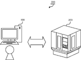
- the screen creation system 300 of the present disclosure comprises a screen creation device 100 and a numerical control device 200 as shown in FIG.
- the screen creation device 100 is implemented in an information processing device such as a PC (personal computer), for example.
- Dedicated software for creating an operation screen for the numerical control device 200 is installed in the screen creation device 100 .
- a user operates software to create a UI screen.
- a UI screen created by dedicated software is transferred to the numerical controller 200 and displayed on the numerical controller 200 .
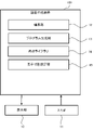
- FIG. 2 is a block diagram of the screen creation device 100 that constitutes the screen creation system 300.
- the screen creation device 100 includes a display section 10 , an input section 11 , an editing section 12 , a program generation section 13 , a component library 14 and a display state setting section 15 .
- the editing unit 12 displays the UI editing screen 20 on the display unit 10 of the screen creation device 100 and accepts editing operations by the user.
- the editing unit 12 updates the screen layout and component properties (attributes, execution functions (operations)) according to user input.
- the program generation unit 13 converts the UI screen layout and component properties created by the editing unit 12 into an executable program.
- the executable program is installed in the numerical controller 200 and functions as a UI screen.
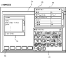
- FIG. 3 is an example of the UI edit screen 20.
- the UI editing screen 20 of FIG. 3 is composed of a UI editing area 21, a property display area 22, and a parts library display area 23.
- FIG. A component to be arranged on the UI screen can be selected from the component library display area 23 .
- Five components are arranged in the UI editing area 21 .
- One of the five operation buttons 24 is in the selected state.
- Properties of the selected operation button 24 are displayed in the property display area 22 .
- visual information such as the size, shape, and coordinates of parts, numeric values displayed on parts, icons, labels such as character strings, types of parts, names of parts, operation of parts (execution function), etc. Information about parts can be set.
- the parts library 14 stores the parts of the UI screen.
- Parts include a single part and a composite part 50 .
- a single part is a single part.
- Single parts include, but are not limited to, operation buttons 24, key input buttons, labels, and the like.
- a composite part 50 is a part obtained by combining a plurality of single parts.
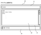
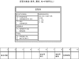
- a composite component 50 (program editing component) in FIG. 4 is composed of a plurality of single components (a label display component 31, a figure display component 32, a multiline character string display component 33, and an input reception component 34).
- the label display component 31 is a component that displays a character string.
- the program name "O0003" is displayed.
- the graphic display component 32 is a component used for screen design. Here it is with a blue background.
- the multi-line character string display component 33 is a component that displays a plurality of character strings.
- the machining program is displayed on the multi-line character string display component 33 .
- the input reception component 34 receives input of a character string to be edited. By pressing the “Enter” key, the character string input to the input reception component 34 is reflected in the multi-line character string display component 33 .
- a UI screen on which the composite part 50 is arranged will be described with reference to FIG.
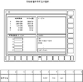
- a base component 51 and a composite component 50 are arranged in the UI editing area 21 of FIG.
- operation buttons 24 for operating the UI screen are arranged in the lower and right regions of the base component 51 .
- a composite part 50 or a single part can be placed in the central area of the base part 51 .
- Four composite components 50 (a coordinate display component, an information display component, a manual numerical command input component, and a program display component) are arranged on the base component 51 of FIG.
- the operation button 24 of the base component 51 is associated with the display state of the composite component 50 . A relationship between the operation button 24 and the composite part 50 will be described later.
- the display state setting unit 15 receives the settings of the operation buttons 24 for the display state of the composite part 50, and creates display state information based on the acquired information.
- the display state information associates the composite component 50 , the display state of the composite component 50 , and the layout of the operation button 24 for each display state of the composite component 50 .
- the display state of the composite part 50 includes at least one of the mode of the numerical controller 200 , “display/non-display” of the composite part 50 , and “selection/non-selection” of the composite part 50 .
- a mode of the numerical controller 200 is a working state of the numerical controller 200 .
- the modes of the numerical controller 200 include a mode set by the operator of the numerical controller 200, a mode automatically started by a signal from the numerical controller 200, and the like.
- Modes set by the operator include a memory mode, an MDI mode, and the like.
- Modes that occur automatically include execution of workpiece coordinate measurement operations. It should be noted that "mode independent" in the following description means that the mode of the numerical control device 100 does not affect the settings of the operation buttons 24. FIG.
- Display of the composite component 50 means whether or not the composite component 50 included in the UI screen is displayed. There is more than one UI screen. Different composite parts 50 are arranged on a plurality of UI screens. Whether or not the composite part 50 is displayed changes depending on which UI screen is displayed. In addition, as shown in FIG. 6, two or more composite parts 50 may be overlapped and arranged in one display area of the UI screen. When one of the overlapping composite parts 50 is displayed, the other composite parts 50 are hidden.
- Selection/non-selection of the composite part 50 means whether or not the composite part 50 included in the UI screen is selected. Selection/non-selection of the composite part 50 changes according to the operator's operation. In the following description, "not depending on selection” means that selection/non-selection does not affect the setting of the operation button 24. FIG.
- FIG. 7 to 11 show setting examples of the operation button 24 for each display state of the composite part 50.
- the coordinate display component has four operation buttons 24 "display switching", “machine coordinates”, and “absolute coordinates” for the display states of "display”, “selection independent”, and “mode independent”. "Relative coordinates” are set.
- FIG. 8 in the information display component, three operation buttons 24 “display switching”, “modal list”, and “work” are provided for the display states of "display”, “selection independent”, and “mode independent”. /Tool information” is set.
- the operation button 24 "modal list” and “work/tool information” switches the display of the information display component.
- different operation buttons 24 are set for each mode.
- buttons 24 "display switching", “copy”, “paste”, “cut”, “delete”, “display”, “copy”, “paste”, “cut”, “delete”, “Search”, "machining cycle”, “measurement cycle”, and “delete all” are set.
- eight operation buttons 24 "display change”, “copy”, “paste”, “cut”, “delete”, “search” and “MDI mode” are displayed. "History” and “Delete all” are set.
- four operation buttons 24 "display switching", “MST”, "G00", “G01” is set.
- the operation buttons 24 "MST”, “G00”, and “G01” switch the display of manual numerical command parts. As shown in FIG. 11, in the fixed phrase component, four operation buttons 24 “display change”, “fixed phrase insertion”, “fixed phrase “Register” and “Delete fixed phrase registration” are set. The operation buttons 24 “registration of fixed phrase”, “delete registration of fixed phrase”, and “insert fixed phrase” are used to register and delete fixed phrases, and to insert the registered fixed phrases into program editing components.
- the user sets the operation button 24 for each display state of the composite part 50 on the screen creation device 100 .
- the numerical control device 200 automatically switches the arrangement of the operation buttons 24 based on the operation buttons 24 for each display state set by the screen creation device 100 and the actual display state of the UI screen.
- the numerical controller 200 will be described below.
- FIG. 12 is a block diagram of the numerical controller 200.
- the numerical controller 200 includes a display section 61 , an input section 62 , a UI screen display section 63 , an arrangement determination section 64 and an operation button switching section 65 .
- the UI screen display unit 63 displays the UI screen created by the screen creation device 100 on the display unit 61 such as a display.
- the layout determination unit 64 determines the layout of the operation buttons 24 for each display state of the UI screen based on the display state information.
- An example of a method of determining the layout of the operation buttons 24 will be described below, but the method of determining the layout is not limited to this.
- the layout of the operation buttons 24 corresponding to this display state is set as the layout of the operation buttons 24 on the UI screen. For example, in FIGS. 9 to 11, the item "selected/non-selected" is "selected”, so the layout of the operation buttons 24 corresponding to this display state is the layout of the operation buttons 24 on the UI screen.
- a second method is to arrange the operation buttons 24 of the composite parts 50 having the same "mode” together when there are a plurality of composite parts 50 with “display” and "no selection dependence" in the display state information.
- the operation buttons 24 When the operation buttons 24 are arranged collectively, the operation buttons 24 may be arranged in such a manner that there are no empty operation buttons 24, such as automatic arrangement with right justification or automatic arrangement with left justification, or they may be arranged at a fixed position. good too.
- the present disclosure places the operating button 24 at a fixed position.
- the coordinate display component in FIG. 7 and the information display component in FIG. 8 are both "display” and "mode-independent".
- a combination of the layout of the operation buttons 24 and the layout of the operation buttons 24 set for the information display component is the layout of the operation buttons 24 on the UI screen.
- FIG. 13 shows the determination result of the arrangement determination unit 64.
- the operation button layout table stores the layout of the operation buttons 24 on the UI screen for each display state.
- the operation button layout table includes a display state of each composite part 50 such as "composite part name”, “display/non-display”, “mode” of the numerical controller 200, and "selected/non-selected", and ""Arrangement of operation buttons" is associated.
- the operation button switching unit 65 detects changes in the display state (display/non-display of the composite part 50, mode of the numerical controller 200, selection/non-selection of the composite part 50) and switches the arrangement of the operation buttons 24.
- FIG. 18 shows the UI screen when the operation button 24 "MST” is pressed.
- the “manual numerical command (MST)” is switched to the “manual numerical command (G00)” as shown in FIG.
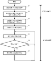
- FIG. 20 is a flow chart showing the operation of the screen creation system 300 of the present disclosure.
- steps S1 to S2 are processes executed by the screen creation device 100
- steps S3 to S7 are processes executed by the numerical control device 200.
- FIG. First the composite part 50 is arranged on the UI editing screen 20 (step S1).
- Display state information is created by setting the operation button 24 for each display state for the composite part 50 arranged on the UI screen (step S2).
- the operation buttons 24 in each display state of the composite part 50 are set.
- the display state includes the mode of the numerical controller 200, display/non-display of the composite part 50, selection/non-selection of the composite part 50, and the like.
- the numerical control device 200 reads the UI screen created by the screen creation device 100 and the display state information (step S3). Based on the display state information, the numerical controller 200 determines the layout of the operation buttons 24 in each display state of the UI screen, and creates an layout table of the operation buttons 24 on the UI screen (step S4). The numerical control device 200 displays the UI screen created by the screen creation device 100 and monitors changes in the display state (step S5). When the numerical control device 200 detects a change in the display state due to an operator's operation or an internal signal of the numerical control device 200 (step S6; Yes), the arrangement of the operation buttons 24 is changed according to the change in the display state (step S7). . If the arrangement of the operation buttons 24 is changed, the process proceeds to step S5 to continue monitoring. If the display state does not change (step S6; No), the process proceeds to step S5 to continue monitoring.
- the numerical controller 200 determines the layout of the operation buttons 24 for each display state of the UI screen. .
- Numerical controller 200 detects a change in the display state and automatically changes the arrangement of operation buttons 24 .
- it is easy to create a UI screen.
- the setting of the operation buttons 24 for each composite part 50 can be reused in different UI screens, so it is easier than setting the layout of the operation buttons 24 for each UI screen.
- a CPU 111 included in the numerical controller 200 is a processor that controls the numerical controller 200 as a whole.
- the CPU 111 reads the system program processed in the ROM 112 via the bus and controls the entire numerical controller 200 according to the system program.
- the RAM 113 temporarily stores calculation data, display data, various data input by the user via the input unit 62, and the like.
- the display unit 61 is a monitor attached to the numerical controller 200 or the like.
- the display unit 61 displays an operation screen, a setting screen, and the like of the numerical controller 200 .
- the input unit 62 is integrated with the display unit 61, or is a keyboard, touch panel, or the like that is separate from the display unit 61.
- the user operates the input unit 62 to perform input to the screen displayed on the display unit 61 .
- the display unit 61 and the input unit 62 may be mobile terminals.
- the non-volatile memory 114 is, for example, a memory that is backed up by a battery (not shown) so that the memory state is retained even when the power of the numerical controller 200 is turned off.
- the non-volatile memory 114 stores a program read from an external device via an interface (not shown), a program input via the input unit 62, and various data (for example, , setting parameters obtained from the machine tool, etc.) are stored.
- Programs and various data stored in the non-volatile memory 114 may be developed in the RAM 113 at the time of execution/use.
- Various system programs are pre-written in the ROM 112 .
- the controller 40 that controls the tool of the machine tool converts the axis movement command from the CPU 111 into a pulse signal and outputs it to the driver 41 .
- a driver 41 converts the pulse signal into a current to drive a servomotor of the machine tool.
- the servo motors move tools and tables under the control of the numerical controller 200 .
- the screen creation device 100 does not include the controller 40 and the driver 41, but has substantially the same hardware configuration as in FIG. A description of the hardware configuration of the screen creation device 100 is omitted.
- REFERENCE SIGNS LIST 100 screen creation device 200 numerical control device 300 screen creation system 10 display unit 11 input unit 12 editing unit 13 program generation unit 14 component library 50 composite component 61 display unit 62 input unit 63 UI screen display unit 64 layout determination unit 65 operation button switching Part 111 CPU 112 ROMs 113 RAM 114 non-volatile memory
Landscapes
- Engineering & Computer Science (AREA)
- Human Computer Interaction (AREA)
- Physics & Mathematics (AREA)
- General Physics & Mathematics (AREA)
- General Engineering & Computer Science (AREA)
- Theoretical Computer Science (AREA)
- Manufacturing & Machinery (AREA)
- Automation & Control Theory (AREA)
- Numerical Control (AREA)
Priority Applications (5)
| Application Number | Priority Date | Filing Date | Title |
|---|---|---|---|
| DE112021007546.2T DE112021007546T5 (de) | 2021-06-23 | 2021-06-23 | Numerische steuervorrichtung, bildschirm-erstellungssystem und speichermedium zum speichern einer durch die numerische steuervorrichtung lesbaren anweisung |
| CN202180099486.7A CN117597640A (zh) | 2021-06-23 | 2021-06-23 | 数值控制装置、画面生成系统以及存储数值控制装置可读取的命令的存储介质 |
| JP2023529329A JP7704853B2 (ja) | 2021-06-23 | 2021-06-23 | 数値制御装置、画面作成システム、及び数値制御装置が読み取り可能な命令を記憶する記憶媒体 |
| PCT/JP2021/023828 WO2022269816A1 (ja) | 2021-06-23 | 2021-06-23 | 数値制御装置、画面作成システム、及び数値制御装置が読み取り可能な命令を記憶する記憶媒体 |
| US18/568,349 US20240288983A1 (en) | 2021-06-23 | 2021-06-23 | Numerical control device, screen creation system, and storage medium for storing instruction readable by numerical control device |
Applications Claiming Priority (1)
| Application Number | Priority Date | Filing Date | Title |
|---|---|---|---|
| PCT/JP2021/023828 WO2022269816A1 (ja) | 2021-06-23 | 2021-06-23 | 数値制御装置、画面作成システム、及び数値制御装置が読み取り可能な命令を記憶する記憶媒体 |
Publications (2)
| Publication Number | Publication Date |
|---|---|
| WO2022269816A1 true WO2022269816A1 (ja) | 2022-12-29 |
| WO2022269816A9 WO2022269816A9 (ja) | 2023-09-28 |
Family
ID=84545373
Family Applications (1)
| Application Number | Title | Priority Date | Filing Date |
|---|---|---|---|
| PCT/JP2021/023828 Ceased WO2022269816A1 (ja) | 2021-06-23 | 2021-06-23 | 数値制御装置、画面作成システム、及び数値制御装置が読み取り可能な命令を記憶する記憶媒体 |
Country Status (5)
| Country | Link |
|---|---|
| US (1) | US20240288983A1 (https=) |
| JP (1) | JP7704853B2 (https=) |
| CN (1) | CN117597640A (https=) |
| DE (1) | DE112021007546T5 (https=) |
| WO (1) | WO2022269816A1 (https=) |
Cited By (1)
| Publication number | Priority date | Publication date | Assignee | Title |
|---|---|---|---|---|
| WO2026047830A1 (ja) * | 2024-08-27 | 2026-03-05 | ファナック株式会社 | 状態表示装置、及びコンピュータが読み取り可能な記憶媒体 |
Citations (3)
| Publication number | Priority date | Publication date | Assignee | Title |
|---|---|---|---|---|
| JPH0272412A (ja) * | 1988-09-08 | 1990-03-12 | Fanuc Ltd | 自動プログラミング方法 |
| JPH04148306A (ja) * | 1990-10-11 | 1992-05-21 | Fanuc Ltd | C軸加工プログラム作成方式 |
| JP2019211827A (ja) * | 2018-05-31 | 2019-12-12 | ファナック株式会社 | 支援装置 |
Family Cites Families (34)
| Publication number | Priority date | Publication date | Assignee | Title |
|---|---|---|---|---|
| US5086513A (en) * | 1989-04-12 | 1992-02-04 | General Electric Company | Digital radio transceiver programmer with advanced user interface |
| JPH09244728A (ja) * | 1996-03-13 | 1997-09-19 | Fanuc Ltd | オンライン端末として利用されるcnc装置のデータ表示・入力方法 |
| JP2002182914A (ja) * | 2000-12-18 | 2002-06-28 | Canon Inc | 画面遷移表示装置、画面遷移表示方法および記憶媒体 |
| US8204618B2 (en) * | 2008-03-24 | 2012-06-19 | Hypertherm, Inc. | Method and apparatus for operating an automated high temperature thermal cutting system |
| JP2004126956A (ja) | 2002-10-02 | 2004-04-22 | Okuma Corp | 数値制御装置 |
| JP2004206550A (ja) * | 2002-12-26 | 2004-07-22 | Fanuc Ltd | 数値制御装置 |
| WO2006009001A1 (ja) * | 2004-07-20 | 2006-01-26 | Matsushita Electric Industrial Co., Ltd. | ガイダンス表示装置 |
| JP2007069330A (ja) * | 2005-09-08 | 2007-03-22 | Fanuc Ltd | 放電加工装置の加工条件設定方法 |
| JP4657265B2 (ja) * | 2007-07-30 | 2011-03-23 | 京セラ株式会社 | 文字入力装置及び表示制御方法 |
| JP5184008B2 (ja) * | 2007-09-03 | 2013-04-17 | ソニーモバイルコミュニケーションズ, エービー | 情報処理装置および携帯電話端末 |
| US8688258B2 (en) * | 2008-09-11 | 2014-04-01 | Rockwell Automation Technologies, Inc. | Method of controlling a machine tool |
| DE202010017198U1 (de) * | 2010-01-19 | 2011-04-07 | Koenig & Bauer Aktiengesellschaft | Rollenwechsler mit einer Absicherung eines Sicherheitsbereiches |
| JP5754410B2 (ja) * | 2012-04-13 | 2015-07-29 | トヨタ自動車株式会社 | 表示装置 |
| JP5444489B2 (ja) * | 2012-06-13 | 2014-03-19 | ファナック株式会社 | 数値制御装置のシミュレーション装置 |
| JP5426727B2 (ja) * | 2012-06-15 | 2014-02-26 | ファナック株式会社 | 仮想操作盤を表示する数値制御装置 |
| ES2634316T3 (es) * | 2013-07-30 | 2017-09-27 | Dmg Mori Co., Ltd. | Sistema de control para controlar la operación de una máquina herramienta de control numérico, y dispositivos de control de extremo trasero y de extremo delantero para uso en tal sistema |
| JP5766762B2 (ja) * | 2013-10-15 | 2015-08-19 | ファナック株式会社 | 動作設定画面を備えた数値制御装置 |
| KR102592053B1 (ko) * | 2016-07-04 | 2023-10-23 | 삼성전자주식회사 | 유저 인터페이스 제공 방법 및 이를 지원하는 전자 장치 |
| JP6612799B2 (ja) * | 2017-03-06 | 2019-11-27 | 京セラ株式会社 | 電子機器、制御方法、及び制御プログラム |
| JP6474447B2 (ja) * | 2017-04-06 | 2019-02-27 | ファナック株式会社 | 情報処理装置 |
| JP6705768B2 (ja) * | 2017-04-06 | 2020-06-03 | ファナック株式会社 | 情報処理装置 |
| JP6496345B2 (ja) * | 2017-04-13 | 2019-04-03 | ファナック株式会社 | 数値制御装置 |
| JP6878367B2 (ja) * | 2018-08-29 | 2021-05-26 | ファナック株式会社 | 数値制御装置 |
| JP6943830B2 (ja) * | 2018-10-19 | 2021-10-06 | ファナック株式会社 | 制御装置、通信端末、及び制御システム |
| JP6904994B2 (ja) * | 2019-02-26 | 2021-07-21 | ファナック株式会社 | 画面作成装置及び画面作成システム |
| JP6674076B1 (ja) * | 2019-07-23 | 2020-04-01 | ヤマザキマザック株式会社 | 工作機械、工作機械のための入力支援方法、及び工作機械のためのプログラム |
| JP7396835B2 (ja) * | 2019-08-27 | 2023-12-12 | ファナック株式会社 | 制御装置、及び制御方法 |
| JP7335116B2 (ja) * | 2019-08-29 | 2023-08-29 | ファナック株式会社 | 制御装置、及び制御方法 |
| US11061383B1 (en) * | 2020-02-14 | 2021-07-13 | Dmg Mori Co., Ltd. | Display control device |
| JP7481448B2 (ja) * | 2020-07-08 | 2024-05-10 | ファナック株式会社 | 設定コード生成装置、産業機械、設定コード生成方法及び設定コード生成プログラム |
| TWI757926B (zh) * | 2020-10-22 | 2022-03-11 | 財團法人工業技術研究院 | 工具機數值控制器軟體動態產生裝置及方法 |
| DE112021007522T5 (de) * | 2021-06-22 | 2024-04-04 | Fanuc Corporation | Bildschirm-erstellungsgerät, und computerlesbares speichermedium |
| JP7053974B1 (ja) * | 2021-06-22 | 2022-04-12 | ファナック株式会社 | 画面作成装置、画面作成システム、及びコンピュータが読み取り可能な記憶媒体 |
| CN117480458A (zh) * | 2021-06-23 | 2024-01-30 | 发那科株式会社 | 画面制作装置、计算机可读取的存储介质 |
-
2021
- 2021-06-23 DE DE112021007546.2T patent/DE112021007546T5/de active Pending
- 2021-06-23 CN CN202180099486.7A patent/CN117597640A/zh active Pending
- 2021-06-23 JP JP2023529329A patent/JP7704853B2/ja active Active
- 2021-06-23 WO PCT/JP2021/023828 patent/WO2022269816A1/ja not_active Ceased
- 2021-06-23 US US18/568,349 patent/US20240288983A1/en active Pending
Patent Citations (3)
| Publication number | Priority date | Publication date | Assignee | Title |
|---|---|---|---|---|
| JPH0272412A (ja) * | 1988-09-08 | 1990-03-12 | Fanuc Ltd | 自動プログラミング方法 |
| JPH04148306A (ja) * | 1990-10-11 | 1992-05-21 | Fanuc Ltd | C軸加工プログラム作成方式 |
| JP2019211827A (ja) * | 2018-05-31 | 2019-12-12 | ファナック株式会社 | 支援装置 |
Cited By (1)
| Publication number | Priority date | Publication date | Assignee | Title |
|---|---|---|---|---|
| WO2026047830A1 (ja) * | 2024-08-27 | 2026-03-05 | ファナック株式会社 | 状態表示装置、及びコンピュータが読み取り可能な記憶媒体 |
Also Published As
| Publication number | Publication date |
|---|---|
| US20240288983A1 (en) | 2024-08-29 |
| JPWO2022269816A1 (https=) | 2022-12-29 |
| CN117597640A (zh) | 2024-02-23 |
| WO2022269816A9 (ja) | 2023-09-28 |
| DE112021007546T5 (de) | 2024-02-15 |
| JP7704853B2 (ja) | 2025-07-08 |
Similar Documents
| Publication | Publication Date | Title |
|---|---|---|
| US10423147B2 (en) | Control device for machine tool | |
| JPH0551419B2 (https=) | ||
| US20240272609A1 (en) | Screen creation device, screen creation system, and computer-readable recording medium | |
| US20130338815A1 (en) | Numerical controller for displaying virtual control panel | |
| JP7704853B2 (ja) | 数値制御装置、画面作成システム、及び数値制御装置が読み取り可能な命令を記憶する記憶媒体 | |
| JPH0355259B2 (https=) | ||
| JP7620097B2 (ja) | 画面作成装置、コンピュータが読み取り可能な記憶媒体 | |
| WO2022269813A1 (ja) | 画面作成装置、コンピュータが読み取り可能な記憶媒体 | |
| WO2023042295A1 (ja) | 画面作成装置、及びコンピュータが読み取り可能な記憶媒体 | |
| WO2023033095A1 (ja) | 表示制御装置 | |
| JP7376754B1 (ja) | 画面作成支援装置、画面操作支援装置、及びコンピュータが読み取り可能な記憶媒体 | |
| WO2023002618A1 (ja) | 画面作成装置、コンピュータが読み取り可能な記憶媒体 | |
| US20240094706A1 (en) | Operation panel and machine tool | |
| JP2008191802A (ja) | Ncプログラム編集装置、ncプログラム編集制御プログラム及びncプログラム編集制御用記録媒体 | |
| JP7286839B2 (ja) | 表示制御装置 | |
| WO2023042296A1 (ja) | 画面作成装置、及びコンピュータが読み取り可能な記憶媒体 | |
| WO2024090371A1 (ja) | Ncプログラム作成 | |
| JPH0863218A (ja) | 数値制御装置のプログラム構成表示方式 | |
| JPH08272416A (ja) | Ncプログラムの検索方法 | |
| JP5007801B2 (ja) | Ncプログラム編集装置 | |
| JPH07302107A (ja) | 数値制御装置 | |
| JPH11194810A (ja) | Nc情報編集装置 | |
| JPH077839U (ja) | 数値制御装置 | |
| KR20220160561A (ko) | 프로그램 작성 방법, 프로그램 작성 지원 장치 및 프로그래머블 컨트롤러 | |
| JPH06202906A (ja) | Ncプログラム編集装置 |
Legal Events
| Date | Code | Title | Description |
|---|---|---|---|
| 121 | Ep: the epo has been informed by wipo that ep was designated in this application |
Ref document number: 21947101 Country of ref document: EP Kind code of ref document: A1 |
|
| WWE | Wipo information: entry into national phase |
Ref document number: 2023529329 Country of ref document: JP |
|
| WWE | Wipo information: entry into national phase |
Ref document number: 18568349 Country of ref document: US |
|
| WWE | Wipo information: entry into national phase |
Ref document number: 112021007546 Country of ref document: DE |
|
| WWE | Wipo information: entry into national phase |
Ref document number: 202180099486.7 Country of ref document: CN |
|
| 122 | Ep: pct application non-entry in european phase |
Ref document number: 21947101 Country of ref document: EP Kind code of ref document: A1 |