WO2022219941A1 - ワイパブレードの連結構造 - Google Patents
ワイパブレードの連結構造 Download PDFInfo
- Publication number
- WO2022219941A1 WO2022219941A1 PCT/JP2022/007823 JP2022007823W WO2022219941A1 WO 2022219941 A1 WO2022219941 A1 WO 2022219941A1 JP 2022007823 W JP2022007823 W JP 2022007823W WO 2022219941 A1 WO2022219941 A1 WO 2022219941A1
- Authority
- WO
- WIPO (PCT)
- Prior art keywords
- wiper blade
- wiper
- release lever
- wiper arm
- side walls
- Prior art date
- Legal status (The legal status is an assumption and is not a legal conclusion. Google has not performed a legal analysis and makes no representation as to the accuracy of the status listed.)
- Ceased
Links
Images

Classifications
-
- B—PERFORMING OPERATIONS; TRANSPORTING
- B60—VEHICLES IN GENERAL
- B60S—SERVICING, CLEANING, REPAIRING, SUPPORTING, LIFTING, OR MANOEUVRING OF VEHICLES, NOT OTHERWISE PROVIDED FOR
- B60S1/00—Cleaning of vehicles
- B60S1/02—Cleaning windscreens, windows or optical devices
- B60S1/04—Wipers or the like, e.g. scrapers
- B60S1/32—Wipers or the like, e.g. scrapers characterised by constructional features of wiper blade arms or blades
- B60S1/40—Connections between blades and arms
- B60S1/4006—Connections between blades and arms for arms provided with a hook-shaped end
- B60S1/4009—Connections between blades and arms for arms provided with a hook-shaped end comprising a detachable intermediate element mounted on the hook-shaped end
- B60S1/4016—Connections between blades and arms for arms provided with a hook-shaped end comprising a detachable intermediate element mounted on the hook-shaped end the element being provided with retention means co-operating with the hook-shaped end of the arm
- B60S1/4019—Connections between blades and arms for arms provided with a hook-shaped end comprising a detachable intermediate element mounted on the hook-shaped end the element being provided with retention means co-operating with the hook-shaped end of the arm the retention means being protrusions or holes
Definitions
- the present invention relates to a connection structure for wiper blades.
- the wiper device includes a wiper motor as a drive source, a wiper arm that is swung by the drive of the wiper motor, and a wiper blade attached to the tip side of the wiper arm.
- the wiper arm and the wiper blade are connected by a connection structure described in Patent Document 1, for example.
- the wiper arm and the wiper blade are connected by connecting the U-shaped hook portion of the wiper arm to a connector provided on the wiper blade.
- connection structure of the wiper arm and the wiper blade described in Patent Document 1 by operating a release lever for releasing the connection provided on the connector on the wiper blade side for the connected wiper arm and the wiper blade, The connection between the wiper arm and the wiper blade is released.
- An object of the present invention is to provide a wiper blade connection structure with improved operability when disconnecting the wiper arm and the wiper blade.
- One aspect of the present invention includes a wiper arm, a wiper blade connected to the wiper arm, a U-shaped engaging portion provided on the wiper arm, and a U-shaped engaging portion provided on the wiper blade and connected to the engaging portion.
- a wiper blade connecting structure comprising a connecting portion, wherein the engaging portion has a distal end side extending portion having a through hole formed therein, the connecting portion includes a pair of side walls facing each other; A cylindrical portion that is joined to the pair of side walls and engages with the engaging portion, a lever portion that is provided on the cylindrical portion and extends along the pair of side walls, and is arranged to face the lever portion.
- lever portion has flexibility such that it bends in a direction away from the bridging portion, and a projecting portion that can be fitted into the through hole. and a tip end of the lever portion protrudes outside the connecting portion.
- connection structure between the wiper arm and the wiper blade it is possible to improve the operability when the connection is released.
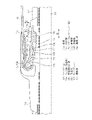
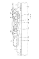
- FIG. 2 is a partially enlarged sectional view showing the detailed structure of the connection structure of the wiper blades shown in FIG. 1;
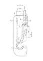
- FIG. 3 is a cross-sectional view showing the structure of a connecting portion of the wiper blade shown in FIG. 2;
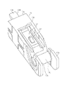
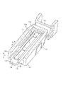
- FIG. 3 is a perspective view showing the structure of a protruding portion in the connecting portion shown in FIG. 2;
- FIG. 3 is a partial cross-sectional view showing how a wiper arm is attached to the connecting portion of the wiper blade shown in FIG. 2 ;
- FIG. 3 is a partial cutaway view showing the structure of a rib provided on a lever portion of the connecting portion shown in FIG. 2;
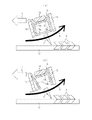
- FIG. 3 is a perspective view showing a contact surface in the connecting portion shown in FIG. 2; It is a figure which shows the state of the connection part at the time of wiping of the wiper arm shown in FIG. 2, (a) is a schematic diagram which shows the effect of a connection part, (b) is a schematic diagram which shows the defect of a connection part.
- the connection structure of the wiper blades 12 shown in FIG. 1 forms a wiper device (not shown) for wiping glass 16 (see FIG. 8) provided in a vehicle such as an automobile, for example. 2, the wiper blade 12 connected to the wiper arm 10, a U-shaped hook portion (engagement portion) 10a provided on the wiper arm 10, and the wiper blade 12 and a connecting portion 13 connected to the hook portion 10a.
- the wiper arm 10 is rotatably supported by an arm head 11 .
- the wiper blade 12 is rotatably connected to a portion near the tip of the wiper arm 10 in the longitudinal direction L of the wiper blade 12 .
- an output shaft (not shown) of a wiper motor forming the wiper device is fixed to the base end of the wiper arm 10 .
- the output shaft of the wiper motor rotates forward and backward, causing the wiper arm 10 to swing.
- the blade rubber 14 provided in the wiper blade 12 shown in FIG. 2 reciprocally wipes a predetermined range on the glass 16, and as a result, the rainwater or the like adhering to the wiped surface of the glass 16 is wiped off.
- the wiper arm 10 and the wiper blade 12 are connected by engaging the hook portion 10a of the wiper arm 10 with the connecting portion 13 of the wiper blade 12 .
- a projecting portion 13f provided on a release lever (lever portion) 13d of the connecting portion 13 of the wiper blade 12 is inserted into the through hole 10c provided in the tip end side extending portion 10b of the hook portion 10a of the wiper arm 10.
- the wiper arm 10 and the wiper blade 12 are connected.
- the hook portion 10a of the wiper arm 10 will be described.
- the hook portion 10a which is the engaging portion of the wiper arm 10
- the distal end side extending portion 10b has a flat upper surface 10d.
- a through-hole 10c is provided in the area where the upper surface 10d of the distal end side extending portion 10b is formed.
- the connecting portion 13 provided on the wiper blade 12 is joined to a pair of side walls 13a and 13b facing each other and to the pair of side walls 13a and 13b, and engages with the hook portion 10a. and a cylindrical portion 13c that fits.
- a shaft portion 13s shown in FIG. 2 is arranged inside the cylindrical portion 13c, and the side walls 13a and 13b are bearing portions.
- the coupling portion 13 is provided in the cylindrical portion 13c and arranged to face a release lever 13d extending along the pair of side walls 13a and 13b and a part of the release lever 13d. and a joined plate-like bridging portion 13g. And the connection part 13 is covered with the cover 15, as shown in FIG.
- the release lever 13d has flexibility to bend in the direction away from the bridging portion 13g (the bending direction P). Furthermore, the release lever 13 d has a projection 13 f that can be fitted into the through hole 10 c of the tip end side extension 10 b of the wiper arm 10 .
- the projecting portion 13f is provided on the lower surface 13k, which is the surface of the release lever 13d on the bridging portion 13g side.
- the release lever 13d is a member that is operated to release the connection between the wiper arm 10 and the wiper blade 12. By performing an operation to bend the release lever 13d in the bending direction P, the release lever 13d is released. The protrusion 13f is removed from the through hole 10c of the wiper arm 10 and the wiper arm 10 is released. Thereby, the connection between the wiper arm 10 and the wiper blade 12 is released.
- the tip portion 13 e of the release lever 13 d protrudes outside the connecting portion 13 .
- the tip portion 13e of the release lever 13d protrudes outward from the side walls 13a and 13b of the connecting portion 13 and the bridging portion 13g.
- the bridging portion 13g is a member joined to both side walls 13a and 13b, and increases the rigidity of the side walls 13a and 13b, which are bearing portions of the connecting portion 13. As shown in FIG. 3, the bridging portion 13g is preferably provided in a thin plate shape so as not to interfere with the stroke S of the release lever 13d, but is not limited to a plate shape.
- the release lever 13d is connected to a base portion 13m provided on the cylindrical portion 13c, a first portion 13h arranged on the side of the cylindrical portion 13c, and a side opposite to the side of the cylindrical portion 13c. and a second portion 13i disposed on the distal end side of the first portion 13h and connected to the first portion 13h. That is, the release lever 13d is composed of a root portion 13m, a first portion 13h and a second portion 13i, and the tip portion 13e is included in the second portion 13i. In other words, the portion of the release lever 13d protruding outside the connecting portion 13 is part of the second portion 13i including the tip portion 13e. Specifically, the portion of the second portion 13i of the release lever 13d located within the connecting portion 13 faces the bridging portion 13g, and the other portion of the second portion 13i protrudes outward from the connecting portion 13. ing.
- the first portion 13h of the release lever 13d is such that the lower surface 13k, which is the surface of the first portion 13h on the bridging portion 13g side, can come into contact with the distal end side extending portion 10b of the wiper arm 10. It's becoming Specifically, when the wiper arm 10 and the wiper blade 12 are connected at the connecting portion 13, the lower surface 13k of the first portion 13h of the release lever 13d contacts the upper surface 10d of the distal end side extending portion 10b of the wiper arm 10. It is designed to touch. Specifically, the lower surface 13k of the first portion 13h of the release lever 13d is inclined at an angle ⁇ with respect to the horizontal plane toward the tip of the release lever 13d.
- the lower surface 13k of the first portion 13h of the release lever 13d is inclined toward the distal end of the release lever 13d with respect to the upper surface 13j of the second portion 13i, which is parallel to the horizontal plane.
- ⁇ tilted As an example, the angle ⁇ is 1°. That is, the lower surface 13k of the first portion 13h is inclined by 1° toward the direction opposite to the bending direction P toward the tip of the release lever 13d.
- the second portion 13i of the release lever 13d is arranged closer to the bridging portion 13g than the first portion 13h in the first direction Q parallel to the bending direction P of the release lever 13d. ing.
- the second portion 13i is arranged in a direction closer to the bridging portion 13g than the first portion 13h.
- the second portion 13i is arranged in a direction opposite to the bending direction P from the first portion 13h. That is, the second portion 13i is provided so as to form a step in the direction opposite to the bending direction P from the first portion 13h.
- the distal end side extending portion 10b of the wiper arm 10 can be arranged in the space on the side of the lower surface 13k formed by the step between the first portion 13h and the second portion 13i.
- ribs 13n extending along the second direction R are provided on both side portions of the first portion 13h and the second portion 13i of the release lever 13d. Specifically, ribs 13n that stand up along the first direction Q are provided on both side ends in the width direction of the first portion 13h and the second portion 13i of the release lever 13d. The ribs 13n are provided only on both sides of the first portion 13h and the second portion 13i, and are not provided on the root portion 13m.
- the release lever 13d of the present embodiment is provided so that the vicinity of the tip portion 13e of the release lever 13d protrudes outward from the connecting portion 13, and the length of the release lever 13d is increased.
- the release lever 13d since the release lever 13d is long, even if the release lever 13d is pushed up in the bending direction P when releasing the connection between the wiper arm 10 and the wiper blade 12, the protrusion 13f may not follow. have a nature.
- the first portion 13h and the second portion 13i of the release lever 13d are stepped, the strength of the release lever 13d itself may be reduced.
- the ribs 13n are provided on both sides (both sides) of only the first portion 13h and the second portion 13i, and the ribs 13n are not provided on the root portion 13m. That is, the rigidity of the first portion 13h and the second portion 13i is increased by the rib 13n, and the rigidity of the root portion 13m is kept from being increased. As a result, when the release lever 13d is pushed up in the bending direction P, the release lever 13d can be reliably bent in the bending direction P, and the first portion 13h and the second portion 13i are separated from each other. Since the rigidity is enhanced, the protrusion 13f can follow.
- the release lever 13d of the present embodiment has a tip portion 13e protruding outside the connecting portion 13 in order to improve operability, and the length from the root portion 13m to the tip portion 13e is increased.
- a bridging portion 13g connecting the side walls 13a and 13b is provided as part of the release lever 13d (a part of the second portion 13i) in order to increase the rigidity of the side walls 13a and 13b, which are bearing portions. ) are provided facing each other. Therefore, provision of the bridging portion 13g makes it difficult to ensure a sufficient stroke S in the bending direction P of the second portion 13i including the tip portion 13e of the release lever 13d.
- the release lever 13d If the stroke amount of the release lever 13d in the bending direction P is insufficient, the protrusion 13f will not easily come off from the through hole 10c of the wiper blade 12 when the wiper arm 10 and the wiper blade 12 are disconnected. Therefore, in the release lever 13d, a step is provided between the first portion 13h and the second portion 13i to secure the stroke amount of the release lever 13d in the bending direction P and to Ribs 13n are provided at the portions (both end portions) to increase the rigidity of the first portion 13h and the second portion 13i. However, since the rib 13n is not provided at the root portion 13m of the release lever 13d, the rigidity of the root portion 13m is low, and the release lever 13d can be bent at the root portion 13m.
- the release lever 13d when the release lever 13d is bent in the bending direction P when the wiper arm 10 and the wiper blade 12 are disconnected, the first portion 13h and the second portion 13i have high rigidity, so that the projecting portion 13f is moved to follow. , the protrusion 13f is removed from the through hole 10c, and the connection between the wiper arm 10 and the wiper blade 12 can be released. Therefore, by adopting the release lever 13d of the present embodiment, it is possible to release the connection between the wiper arm 10 and the wiper blade 12 while improving the operability of the release lever 13d when releasing the connection between the wiper arm 10 and the wiper blade 12. can be done with certainty.
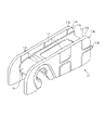
- contact surfaces 13r protruding portions protruding from the opposing surfaces 13p and 13q are provided on the opposing surfaces 13p and 13q of the pair of side walls 13a and 13b of the connecting portion 13, respectively.
- the facing surface 13p of the side wall 13a is provided with a plurality of contact surfaces 13r projecting from the facing surface 13p
- the facing surface 13q of the side wall 13b is also provided with a plurality of contact surfaces 13r projecting from the facing surface 13q.
- a contact surface 13r is provided.
- the wiper arm 10 when the wiper arm 10 is connected to the connecting portion 13, the side portion of the wiper arm 10 can be brought into contact with the contact surface 13r. Vibration can be suppressed. As a result, damage to the wiper arm 10 and the connecting portion 13 can be reduced.
- the connecting portion 13 is provided with a bridging portion 13g connected to each of the pair of opposing side walls 13a and 13b. .
- the rigidity of the side walls 13a and 13b, which are bearing portions, can be increased.
- connection portion 13 has a relatively large number of cavities inside, and as a result, the rigidity of the side walls 13a and 13b is low. Therefore, when a large stress V is applied to the side wall 13a, the side wall 13a collapses, and the wiping performance of the wiper arm 10 deteriorates.
- a bridging portion 13g connecting the side walls 13a and 13b is provided, thereby increasing the rigidity of the side walls 13a and 13b. ing.
- V a large stress
- FIG. 8B a large stress V as shown in FIG. 8B is applied to the side wall 13a or 13b during the wiping operation of the wiper arm 10
- the side wall 13a or 13b will not collapse or be damaged. Wiping performance of the wiper arm 10 is not impaired.
- the strength of the connecting portion 13 is increased, and the distal end portion 13e of the release lever 13d protrudes outside the connecting portion 13.
- the operability when disconnecting the wiper blade 12 can be improved.
- the connecting structure of the wiper blades 12 may be applied to a rear wiper device for wiping the rear glass of a vehicle such as an automobile, or to a wiper device mounted on the front side of a vehicle such as an automobile. may apply. Furthermore, it can also be applied to a wiper device mounted on a ship, an aircraft, a railroad vehicle, or the like.
- the wiper arm 10 in the above embodiment may be molded from a resin material, or may be molded from a metal material.
Landscapes
- Engineering & Computer Science (AREA)
- Mechanical Engineering (AREA)
- Ink Jet (AREA)
- Pivots And Pivotal Connections (AREA)
- Switches With Compound Operations (AREA)
Abstract
Description
15:カバー,16:ガラス
Claims (5)
- ワイパアームと、
前記ワイパアームに連結されるワイパブレードと、
前記ワイパアームに設けられたU字状の係合部と、
前記ワイパブレードに設けられ、前記係合部と連結される連結部と、
を備えたワイパブレードの連結構造であって、
前記係合部は、貫通孔が形成された先端側延在部を有し、
前記連結部は、互いに対向する一対の側壁と、前記一対の側壁に接合され、前記係合部と係合する筒状部と、前記筒状部に設けられ、前記一対の側壁に沿って延びるレバー部と、前記レバー部と対向して配置され、前記一対の側壁に接合された橋渡し部と、を有し、
前記レバー部は、前記橋渡し部から遠ざかる方向に向けて撓む可撓性を有し、前記貫通孔に嵌合可能な突起部を備え、
前記レバー部の先端部は、前記連結部の外部に突出していることを特徴とするワイパブレードの連結構造。 - 前記レバー部は、前記筒状部側に配置された第1部分と、前記筒状部側とは反対側に配置され、前記第1部分と繋がる第2部分と、を有し、
前記第1部分は、該第1部分の前記橋渡し部側の面が前記先端側延在部に当接可能であり、
前記第2部分は、前記レバー部の撓み方向に平行な第1方向において、前記第1部分より前記橋渡し部側に配置されていることを特徴とする請求項1に記載のワイパブレードの連結構造。 - 前記先端側延在部と前記第2部分とは、前記第1方向と交差する第2方向において、少なくとも互いの一部が重なることを特徴とする請求項2に記載のワイパブレードの連結構造。
- 前記第1部分と前記第2部分のそれぞれの幅方向における両側端部に、前記第2方向に沿ってリブが設けられていることを特徴とする請求項3に記載のワイパブレードの連結構造。
- 前記一対の側壁のそれぞれの対向面に、該対向面より突出した突出部が設けられていることを特徴とする請求項1から請求項4のいずれか1項に記載のワイパブレードの連結構造。
Priority Applications (2)
| Application Number | Priority Date | Filing Date | Title |
|---|---|---|---|
| US18/014,473 US12434668B2 (en) | 2021-04-13 | 2022-02-25 | Wiper blade linking structure |
| CN202280005105.9A CN115697790B (zh) | 2021-04-13 | 2022-02-25 | 刮刷器刮片的连结结构 |
Applications Claiming Priority (2)
| Application Number | Priority Date | Filing Date | Title |
|---|---|---|---|
| JP2021067645A JP7636947B2 (ja) | 2021-04-13 | 2021-04-13 | ワイパブレードの連結構造 |
| JP2021-067645 | 2021-04-13 |
Publications (1)
| Publication Number | Publication Date |
|---|---|
| WO2022219941A1 true WO2022219941A1 (ja) | 2022-10-20 |
Family
ID=83639597
Family Applications (1)
| Application Number | Title | Priority Date | Filing Date |
|---|---|---|---|
| PCT/JP2022/007823 Ceased WO2022219941A1 (ja) | 2021-04-13 | 2022-02-25 | ワイパブレードの連結構造 |
Country Status (4)
| Country | Link |
|---|---|
| US (1) | US12434668B2 (ja) |
| JP (1) | JP7636947B2 (ja) |
| CN (1) | CN115697790B (ja) |
| WO (1) | WO2022219941A1 (ja) |
Citations (6)
| Publication number | Priority date | Publication date | Assignee | Title |
|---|---|---|---|---|
| JP2006510529A (ja) * | 2002-12-20 | 2006-03-30 | ヴァレオ システム デシュヤージュ | 本体と、破壊可能な膜材料を介して、本体に両端の一方が接続されたロッキングタングを備える、ワイパーブレードユニットに、ウィンドシールドワイパーアームを接続するためのコネクタ |
| CN2933984Y (zh) * | 2006-06-06 | 2007-08-15 | 罗向东 | 一种汽车雨刷连接件 |
| JP3134473U (ja) * | 2006-10-12 | 2007-08-16 | エイディエム21・カンパニー・リミテッド | ワイパーブレードのアダプタ |
| JP2008037387A (ja) * | 2006-08-10 | 2008-02-21 | Ichikoh Ind Ltd | ワイパー装置 |
| US20130152324A1 (en) * | 2011-12-20 | 2013-06-20 | Jong Wook Lee | Connector Device For Coupling Wiper Arm |
| JP2014507328A (ja) * | 2011-02-02 | 2014-03-27 | フェデラル−モグル エス.エー. | フロントガラスワイパー装置 |
Family Cites Families (17)
| Publication number | Priority date | Publication date | Assignee | Title |
|---|---|---|---|---|
| US2377302A (en) * | 1943-02-04 | 1945-05-29 | Du Pont | Photographic emulsions, developers, and processes of photography |
| US2486477A (en) * | 1945-06-20 | 1949-11-01 | Kennedy Joseph Elliott | Tube mill |
| US2637463A (en) * | 1948-07-02 | 1953-05-05 | Otto M Burkhardt | Cooking utensil |
| US3619589A (en) * | 1967-06-01 | 1971-11-09 | Gte Sylvania Inc | Photographic flashlamp unit |
| DE2637463C3 (de) * | 1976-08-20 | 1979-02-08 | Robert Bosch Gmbh, 7000 Stuttgart | Wischvorrichtung für Scheiben von Kraftfahrzeugen |
| IT7819071A0 (it) * | 1977-01-18 | 1978-01-06 | Bosch Gmbh Robert | Dispositivo tergitore per vetri diveicoli a motore. |
| DE3025734A1 (de) * | 1980-07-08 | 1982-02-04 | Robert Bosch Gmbh, 7000 Stuttgart | Wischvorrichtung fuer scheiben von kraftfahrzeugen |
| DE3619589C2 (de) * | 1986-06-11 | 1996-08-14 | Teves Gmbh Alfred | Wischblatt für Scheibenreinigungsanlagen an Fahrzeugen, insbesondere an Kraftfahrzeugen |
| JP3134473B2 (ja) | 1992-04-03 | 2001-02-13 | チッソ株式会社 | シス−1,4−置換2−ブテン誘導体 |
| DE19745845A1 (de) * | 1997-10-16 | 1999-04-22 | Bosch Gmbh Robert | Lagerteil zum Anlenken eines Wischerblatts |
| JP2000142327A (ja) | 1998-11-16 | 2000-05-23 | Asmo Co Ltd | ワイパブレードの連結装置 |
| US6539576B2 (en) * | 2001-05-22 | 2003-04-01 | Adm 21 Co., Ltd. | Adapter for windshield wiper arms |
| US7207082B2 (en) * | 2002-12-27 | 2007-04-24 | Albert Lee | Windshield wiper frame connector which accommodates different size wiper arms |
| JP2007276669A (ja) | 2006-04-07 | 2007-10-25 | Asmo Co Ltd | 車両用ワイパ及びカバー部材 |
| JP5163502B2 (ja) | 2009-01-09 | 2013-03-13 | 市光工業株式会社 | ワイパーブレード |
| CN102481898B (zh) | 2009-07-10 | 2014-10-29 | 费德罗-莫格尔公司 | 多功能雨刮片连接器和组件 |
| US9663071B2 (en) * | 2014-05-29 | 2017-05-30 | Trico Products Corporation | Wiper adapter and wiper assembly incorporating same |
-
2021
- 2021-04-13 JP JP2021067645A patent/JP7636947B2/ja active Active
-
2022
- 2022-02-25 US US18/014,473 patent/US12434668B2/en active Active
- 2022-02-25 CN CN202280005105.9A patent/CN115697790B/zh active Active
- 2022-02-25 WO PCT/JP2022/007823 patent/WO2022219941A1/ja not_active Ceased
Patent Citations (6)
| Publication number | Priority date | Publication date | Assignee | Title |
|---|---|---|---|---|
| JP2006510529A (ja) * | 2002-12-20 | 2006-03-30 | ヴァレオ システム デシュヤージュ | 本体と、破壊可能な膜材料を介して、本体に両端の一方が接続されたロッキングタングを備える、ワイパーブレードユニットに、ウィンドシールドワイパーアームを接続するためのコネクタ |
| CN2933984Y (zh) * | 2006-06-06 | 2007-08-15 | 罗向东 | 一种汽车雨刷连接件 |
| JP2008037387A (ja) * | 2006-08-10 | 2008-02-21 | Ichikoh Ind Ltd | ワイパー装置 |
| JP3134473U (ja) * | 2006-10-12 | 2007-08-16 | エイディエム21・カンパニー・リミテッド | ワイパーブレードのアダプタ |
| JP2014507328A (ja) * | 2011-02-02 | 2014-03-27 | フェデラル−モグル エス.エー. | フロントガラスワイパー装置 |
| US20130152324A1 (en) * | 2011-12-20 | 2013-06-20 | Jong Wook Lee | Connector Device For Coupling Wiper Arm |
Also Published As
| Publication number | Publication date |
|---|---|
| CN115697790A (zh) | 2023-02-03 |
| JP2022162698A (ja) | 2022-10-25 |
| JP7636947B2 (ja) | 2025-02-27 |
| CN115697790B (zh) | 2025-08-08 |
| US12434668B2 (en) | 2025-10-07 |
| US20230278527A1 (en) | 2023-09-07 |
Similar Documents
| Publication | Publication Date | Title |
|---|---|---|
| JP4067912B2 (ja) | ワイパーブレード用の結合部材及びワイパーブレード | |
| JP4091493B2 (ja) | 連結装置、及びワイパブレード | |
| KR101386917B1 (ko) | 와이퍼 블레이드 | |
| CN105452069B (zh) | 刮水片以及刮水器 | |
| EP1964735B1 (en) | Wiper blade | |
| KR100699187B1 (ko) | 와이퍼 블레이드 | |
| KR101299689B1 (ko) | 와이퍼장치 | |
| JP2022162698A (ja) | ワイパブレードの連結構造 | |
| JP4981626B2 (ja) | 車両用ワイパ装置 | |
| JP6017403B2 (ja) | フローティング部材、及びワイパ装置 | |
| JP2001001868A (ja) | ワイパアーム | |
| WO2014002863A1 (ja) | ワイパブレード | |
| CN108463382A (zh) | 汽车用雨刷片 | |
| US7018228B2 (en) | Electrical connector with a low profile latch | |
| JP2009107420A (ja) | ワイパ装置 | |
| JPH11180263A (ja) | ワイパブレードおよびそれを用いたワイパ装置 | |
| JP2006232078A (ja) | ワイパブレード | |
| JP7292148B2 (ja) | ワイパーブレード | |
| US8910341B2 (en) | Wiper device having improved vibration prevention of wiper strip | |
| JP4950910B2 (ja) | 車両用ワイパ装置 | |
| KR102869051B1 (ko) | 차량용 와이퍼의 채터링 방지 장치 | |
| JP2005001538A (ja) | ワイパーブレード用の結合部材 | |
| JP4124955B2 (ja) | コンビネーションスイッチ | |
| JP2020044923A (ja) | ワイパレバーアッセンブリ及びワイパブレード | |
| JP2024090680A (ja) | ワイパブレード、及びクリップ |
Legal Events
| Date | Code | Title | Description |
|---|---|---|---|
| 121 | Ep: the epo has been informed by wipo that ep was designated in this application |
Ref document number: 22787869 Country of ref document: EP Kind code of ref document: A1 |
|
| NENP | Non-entry into the national phase |
Ref country code: DE |
|
| 122 | Ep: pct application non-entry in european phase |
Ref document number: 22787869 Country of ref document: EP Kind code of ref document: A1 |
|
| WWG | Wipo information: grant in national office |
Ref document number: 202280005105.9 Country of ref document: CN |
|
| WWG | Wipo information: grant in national office |
Ref document number: 18014473 Country of ref document: US |