WO2022209158A1 - 電解液およびリチウムイオン二次電池 - Google Patents
電解液およびリチウムイオン二次電池 Download PDFInfo
- Publication number
- WO2022209158A1 WO2022209158A1 PCT/JP2022/001511 JP2022001511W WO2022209158A1 WO 2022209158 A1 WO2022209158 A1 WO 2022209158A1 JP 2022001511 W JP2022001511 W JP 2022001511W WO 2022209158 A1 WO2022209158 A1 WO 2022209158A1
- Authority
- WO
- WIPO (PCT)
- Prior art keywords
- ion secondary
- active material
- secondary battery
- lithium ion
- electrode active
- Prior art date
Links
Images
Classifications
-
- H—ELECTRICITY
- H01—ELECTRIC ELEMENTS
- H01M—PROCESSES OR MEANS, e.g. BATTERIES, FOR THE DIRECT CONVERSION OF CHEMICAL ENERGY INTO ELECTRICAL ENERGY
- H01M10/00—Secondary cells; Manufacture thereof
- H01M10/05—Accumulators with non-aqueous electrolyte
- H01M10/056—Accumulators with non-aqueous electrolyte characterised by the materials used as electrolytes, e.g. mixed inorganic/organic electrolytes
- H01M10/0564—Accumulators with non-aqueous electrolyte characterised by the materials used as electrolytes, e.g. mixed inorganic/organic electrolytes the electrolyte being constituted of organic materials only
- H01M10/0566—Liquid materials
- H01M10/0569—Liquid materials characterised by the solvents
-
- H—ELECTRICITY
- H01—ELECTRIC ELEMENTS
- H01M—PROCESSES OR MEANS, e.g. BATTERIES, FOR THE DIRECT CONVERSION OF CHEMICAL ENERGY INTO ELECTRICAL ENERGY
- H01M10/00—Secondary cells; Manufacture thereof
- H01M10/05—Accumulators with non-aqueous electrolyte
- H01M10/052—Li-accumulators
- H01M10/0525—Rocking-chair batteries, i.e. batteries with lithium insertion or intercalation in both electrodes; Lithium-ion batteries
-
- H—ELECTRICITY
- H01—ELECTRIC ELEMENTS
- H01M—PROCESSES OR MEANS, e.g. BATTERIES, FOR THE DIRECT CONVERSION OF CHEMICAL ENERGY INTO ELECTRICAL ENERGY
- H01M10/00—Secondary cells; Manufacture thereof
- H01M10/05—Accumulators with non-aqueous electrolyte
- H01M10/056—Accumulators with non-aqueous electrolyte characterised by the materials used as electrolytes, e.g. mixed inorganic/organic electrolytes
- H01M10/0564—Accumulators with non-aqueous electrolyte characterised by the materials used as electrolytes, e.g. mixed inorganic/organic electrolytes the electrolyte being constituted of organic materials only
- H01M10/0566—Liquid materials
- H01M10/0568—Liquid materials characterised by the solutes
-
- H—ELECTRICITY
- H01—ELECTRIC ELEMENTS
- H01M—PROCESSES OR MEANS, e.g. BATTERIES, FOR THE DIRECT CONVERSION OF CHEMICAL ENERGY INTO ELECTRICAL ENERGY
- H01M4/00—Electrodes
- H01M4/02—Electrodes composed of, or comprising, active material
- H01M4/36—Selection of substances as active materials, active masses, active liquids
- H01M4/58—Selection of substances as active materials, active masses, active liquids of inorganic compounds other than oxides or hydroxides, e.g. sulfides, selenides, tellurides, halogenides or LiCoFy; of polyanionic structures, e.g. phosphates, silicates or borates
- H01M4/583—Carbonaceous material, e.g. graphite-intercalation compounds or CFx
- H01M4/587—Carbonaceous material, e.g. graphite-intercalation compounds or CFx for inserting or intercalating light metals
-
- H—ELECTRICITY
- H01—ELECTRIC ELEMENTS
- H01M—PROCESSES OR MEANS, e.g. BATTERIES, FOR THE DIRECT CONVERSION OF CHEMICAL ENERGY INTO ELECTRICAL ENERGY
- H01M2300/00—Electrolytes
- H01M2300/0017—Non-aqueous electrolytes
- H01M2300/002—Inorganic electrolyte
-
- H—ELECTRICITY
- H01—ELECTRIC ELEMENTS
- H01M—PROCESSES OR MEANS, e.g. BATTERIES, FOR THE DIRECT CONVERSION OF CHEMICAL ENERGY INTO ELECTRICAL ENERGY
- H01M2300/00—Electrolytes
- H01M2300/0017—Non-aqueous electrolytes
- H01M2300/0025—Organic electrolyte
- H01M2300/0028—Organic electrolyte characterised by the solvent
- H01M2300/0037—Mixture of solvents
-
- Y—GENERAL TAGGING OF NEW TECHNOLOGICAL DEVELOPMENTS; GENERAL TAGGING OF CROSS-SECTIONAL TECHNOLOGIES SPANNING OVER SEVERAL SECTIONS OF THE IPC; TECHNICAL SUBJECTS COVERED BY FORMER USPC CROSS-REFERENCE ART COLLECTIONS [XRACs] AND DIGESTS
- Y02—TECHNOLOGIES OR APPLICATIONS FOR MITIGATION OR ADAPTATION AGAINST CLIMATE CHANGE
- Y02E—REDUCTION OF GREENHOUSE GAS [GHG] EMISSIONS, RELATED TO ENERGY GENERATION, TRANSMISSION OR DISTRIBUTION
- Y02E60/00—Enabling technologies; Technologies with a potential or indirect contribution to GHG emissions mitigation
- Y02E60/10—Energy storage using batteries
Definitions
- the present invention relates to an electrolyte that can be used in lithium ion secondary batteries, and a lithium ion secondary battery using the electrolyte.
- Lithium-ion secondary batteries which have excellent capacity, are used as power sources for mobile terminals, personal computers, and electric vehicles.
- decarbonization In recent years, there has been an increasing demand for decarbonization, and many efforts are being made to electrify the drive sources of various devices. Along with this, there is a demand for further improvement in the characteristics of lithium ion secondary batteries.
- the inventors of the present invention aimed to improve the characteristics of lithium-ion secondary batteries by optimizing the electrolyte of the lithium-ion secondary batteries.
- Patent Document 1 introduces an electrolytic solution in which LiPF 6 is dissolved at a concentration of 1 mol/L in a mixed non-aqueous solvent in which ethylene carbonate and ethyl methyl carbonate are mixed at a volume ratio of 3:7.
- Patent Document 2 introduces an electrolytic solution in which LiPF 6 is dissolved at a concentration of 1 mol/L in a mixed non-aqueous solvent in which ethylene carbonate, dimethyl carbonate, and ethyl methyl carbonate are mixed at a volume ratio of 3:2:5. .
- chain carbonate is used as the main solvent of the electrolytic solution in the above patent documents.
- the inventor of the present invention found that an alkylene cyclic carbonate and methyl propionate were used in combination as a non-aqueous solvent for the electrolytic solution.
- An application for an ion secondary battery has already been filed (Japanese Patent Application No. 2020-026926).
- the electrolytic solution described above can contribute to improving the characteristics of the lithium ion secondary battery.
- the inventor of the present invention was not satisfied with this, and conducted extensive research to further improve the characteristics.
- the present invention has been made in view of such circumstances, and an object thereof is to provide an electrolytic solution capable of imparting excellent characteristics to a lithium ion secondary battery, and a lithium ion secondary battery exhibiting excellent characteristics. do.
- the inventors of the present invention found that lithium It was found that the characteristics of the ion secondary battery are further improved.
- the inventors of the present invention completed the electrolytic solution of the present invention based on such findings.
- the applicant of the present invention has developed a structure of an electric storage cell and an electric storage device capable of suppressing a decrease in sealing performance as part of efforts to improve the durability of an electric storage device including a lithium ion secondary battery, and has already filed an application.
- Japanese Patent Application No. 2021-003409 Japanese Patent Application No. 2021-003409
- the inventors of the present invention also conducted various studies on the electrolytic solution in order to further improve the sealing performance of the storage cell in the lithium ion secondary battery having the structure. In the process, it was found that by combining the structure with the electrolytic solution of the present invention described above, the sealing property of the storage cell in the lithium ion secondary battery can be further improved, and the lithium ion secondary battery of the present invention completed.
- the electrolytic solution of the present invention that solves the above problems is having an electrolyte comprising a lithium salt and a non-aqueous solvent comprising an alkylene cyclic carbonate and methyl propionate;
- the electrolyte contains 30 mol% or more of a lithium salt other than LiPF 6 with respect to the total lithium salt,
- the nonaqueous solvent is an electrolytic solution containing 75% by volume or more of the methyl propionate.
- the lithium ion secondary battery of the present invention for solving the above problems is a positive electrode having a first current collector and a positive electrode active material layer provided on one surface of the first current collector; It has a second current collector and a negative electrode active material layer provided on one side of the second current collector, and is stacked on the positive electrode while facing the positive electrode active material layer. a negative electrode; a separator disposed between the positive electrode active material layer and the negative electrode active material layer; disposed between the first current collector and the second current collector to surround the positive electrode active material layer and the negative electrode active material layer; and a sealing portion that seals the electrolytic solution in the space between It is a lithium ion secondary battery using the electrolyte solution of the present invention described above as the electrolyte solution.
- the electrolyte solution of the present invention excellent characteristics can be imparted to lithium ion secondary batteries. Moreover, the lithium ion secondary battery of the present invention exhibits excellent characteristics, particularly excellent structural durability.
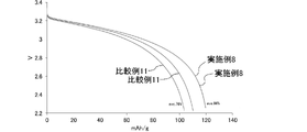
- FIG. 10 is a graph showing changes over time in CC discharge capacity in each lithium ion secondary battery of Example 8 and Comparative Example 11.
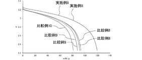
- FIG. 10 is a graph showing changes over time in CC discharge capacity in each lithium ion secondary battery of Example 8 and Comparative Examples 8 to 10.
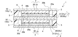
- FIG. 11 is an explanatory diagram schematically showing a lithium ion secondary battery of Example 9;
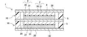
- FIG. 11 is an explanatory diagram schematically showing a lithium-ion secondary battery of Example 10;
- FIG. 11 is an explanatory diagram for explaining measurement positions of the natural peel length in Evaluation Example 9;
- 10 is a graph showing the natural peel length of each test piece in Evaluation Example 9.
- the numerical range "x to y" described in this specification includes the lower limit x and the upper limit y.
- a new numerical range can be formed by arbitrarily combining these upper and lower limits and the numerical values listed in the examples.
- numerical values arbitrarily selected from any of the above numerical ranges can be used as upper and lower numerical values of the new numerical range.
- the electrolytic solution of the present invention can improve the characteristics of lithium ion secondary batteries by providing all of the following (1) to (3).
- the non-aqueous solvent contains 75% by volume or more of methyl propionate.
- the above (1) can contribute particularly to improving the structural durability.
- the above (2) can contribute to smooth charging and discharging among the characteristics of the lithium ion secondary battery. Specifically, it is derived from alkylene cyclic carbonate, and lithium ions are smoothly generated and inserted into and detached from the negative electrode, and the disadvantages of alkylene cyclic carbonate such as high viscosity and high melting point are compensated by methyl propionate.
- the above (3) can contribute to the improvement of the capacity retention rate, output, and the like among the characteristics of the lithium ion secondary battery. It can be said that the electrolytic solution of the present invention can improve the characteristics of the lithium-ion secondary battery by these cooperation.
- the structural durability of the lithium ion secondary battery of the present invention can be improved by providing both (4) and (5) below.
- a positive electrode having a first current collector and a positive electrode active material layer provided on one surface of the first current collector; It has a second current collector and a negative electrode active material layer provided on one side of the second current collector, and is stacked on the positive electrode while facing the positive electrode active material layer.
- a negative electrode a separator disposed between the positive electrode active material layer and the negative electrode active material layer; disposed between the first current collector and the second current collector to surround the positive electrode active material layer and the negative electrode active material layer; and a sealing portion that seals the electrolytic solution in the space between (5)
- the electrolytic solution of the present invention described above is used.
- the above (4) can contribute to suppressing deterioration of the sealing performance among the characteristics of the lithium ion secondary battery.
- the above (5) can further contribute to the improvement of structural durability among the characteristics of the lithium ion secondary battery provided with the above (4), specifically, the improvement of sealing performance.
- the lithium-ion secondary battery of the present invention can realize improvement in its characteristics through these cooperation.
- the electrolytic solution and the lithium ion secondary battery of the present invention will be described below for each component.
- the lithium ion concentration in the electrolytic solution of the present invention is preferably in the range of 0.8 to 1.8 mol / L, more preferably in the range of 0.9 to 1.5 mol / L, from the viewpoint of ionic conductivity.
- the range of 0 to 1.4 mol/L is more preferable, and the range of 1.1 to 1.3 mol/L is particularly preferable.
- the electrolyte used in the electrolytic solution of the present invention contains a lithium salt, and contains 30 mol % or more of the lithium salt other than LiPF 6 with respect to the total lithium salt.
- the electrolytic solution of the present invention may contain LiPF 6 as a lithium salt or may not contain LiPF 6 .
- LiPF 6 is widely used as an electrolyte for electrolyte solutions for lithium ion secondary batteries, and is relatively inexpensive.
- the reason why the electrolytic solution of the present invention uses a lithium salt other than LiPF 6 is as follows.
- LiPF 6 It is known that the reaction of LiPF 6 with water produces hydrogen fluoride. Since a small amount of water is present in the electrolyte of a general lithium ion secondary battery, hydrogen fluoride may be contained in the electrolyte in the lithium ion secondary battery containing LiPF 6 in the electrolyte. It is also known that LiPF 6 is thermally unstable, forming PF 5 at temperatures above 60° C., for example. The PF5 can react with water to produce hydrogen fluoride.
- the inventors of the present invention have studied the composition of the electrolytic solution in order to improve the characteristics of the lithium ion secondary battery.
- hydrogen fluoride and PF 5 present in the electrolyte may corrode the electrodes and containers of the lithium-ion secondary battery, and corrosion of the electrodes and containers may reduce the durability of the lithium-ion secondary battery.
- the lithium ion secondary battery has a structure having a sealing portion between two current collectors as disclosed in Japanese Patent Application No.
- the surface of the metal portion contained in the current collectors corrodes ( Specifically, when fluorinated, the bonding strength between the sealing portion and the current collector is weakened, structurally deteriorating the battery, and the sealing performance of the sealing portion is likely to be reduced. This problem is particularly pronounced when the current collector contains aluminum.
- the inventors of the present invention aimed to suppress the above-mentioned problems caused by LiPF 6 in order to improve the structural durability of lithium ion secondary batteries. They have also found that the above problem is suppressed when the electrolyte contains a lithium salt other than LiPF 6 in an amount of 30 mol % or more with respect to the total lithium salt. Although details will be described in the section of Examples described later, as a result of actual tests by the inventors of the present invention, in a lithium ion secondary battery having a sealing portion between two current collectors, electrolytes other than LiPF 6 When the lithium salt of 30 mol % or more of the total lithium salt is contained, the durability is improved as compared with the case where only LiPF 6 is contained as the electrolyte.
- lithium salts other than LiPF 6 those represented by the following general formula (1) are particularly preferred. Lithium salts of this type are less likely to produce hydrogen fluoride and PF5 .
- R1X1 )( R2SO2 )NLi General formula ( 1 )
- R 1 is hydrogen, halogen, an optionally substituted alkyl group, an optionally substituted cycloalkyl group, an optionally substituted unsaturated alkyl group, a substituent
- R 2 is hydrogen, halogen, an optionally substituted alkyl group, an optionally substituted cycloalkyl group, an optionally substituted unsaturated alkyl group, or a substituent; optionally substituted unsaturated cycloalkyl group, optionally substituted aromatic group, optionally substituted heterocyclic group, optionally substituted alkoxy group, optionally substituted unsaturated alkoxy group, optionally substituted thioalkoxy group, optionally substituted unsaturated thioalkoxy group, CN, SCN, OCN be. Also, R 1 and R 2 may combine with each other to form a ring.
- R a and R b each independently represent hydrogen, halogen, an optionally substituted alkyl group, an optionally substituted cycloalkyl group, or an optionally substituted unsubstituted group.
- R a and R b may combine with R 1 or R 2 to form a ring.
- an optionally substituted alkyl group means an alkyl group in which one or more of the hydrogen atoms in the alkyl group is substituted with a substituent, or an unsubstituted alkyl group. do.
- substituents in the phrase "optionally substituted” include alkyl groups, alkenyl groups, alkynyl groups, cycloalkyl groups, unsaturated cycloalkyl groups, aromatic groups, heterocyclic groups, halogens, OH , SH, CN, SCN, OCN, nitro group, alkoxy group, unsaturated alkoxy group, amino group, alkylamino group, dialkylamino group, aryloxy group, acyl group, alkoxycarbonyl group, acyloxy group, aryloxycarbonyl group, acylamino group, alkoxycarbonylamino group, aryloxycarbonylamino group, sulfonylamino group, sulfamoyl group, carbamoyl group, alkylthio group, arylthio group, sulfonyl group, sulfinyl group, ureido group, phosphoramide group, sulfo group,
- the lithium salt is preferably represented by the following general formula (1-1).
- R 13 and R 14 are each independently C n Ha F b Cl c Br d I e (CN) f (SCN ) g (OCN) h .
- R c and R d each independently represent hydrogen, halogen, an optionally substituted alkyl group, an optionally substituted cycloalkyl group, or an optionally substituted unsubstituted group.
- R c and R d may combine with R 23 or R 24 to form a ring.
- n is preferably an integer of 0 to 6, more preferably an integer of 0 to 4, and particularly preferably an integer of 0 to 2.
- n is preferably an integer of 1 to 8, and 1 to 7 is more preferred, and integers from 1 to 3 are particularly preferred.
- the lithium salt is represented by the following general formula (1-2).
- R 15 SO 2 (R 16 SO 2 )NLi
- R 15 and R 16 are each independently C n Ha F b Cl c Br d Ie .
- n is preferably an integer of 0 to 6, more preferably an integer of 0 to 4, and particularly preferably an integer of 0 to 2.
- n is preferably an integer of 1 to 8, and 1 to 7 is more preferred, and integers from 1 to 3 are particularly preferred.
- the lithium salts represented by the general formula (1), (1-1) or (1-2) are (CF 3 SO 2 ) 2 NLi, (FSO 2 ) 2 NLi, (C 2 F 5 SO 2 ) at least one imide salt selected from 2NLi , FSO2 ( CF3SO2 ) NLi , ( SO2CF2CF2SO2 ) NLi , or ( SO2CF2CF2CF2SO2 ) NLi ; It is preferable to have Of these, (FSO 2 ) 2 NLi improves the output and durability of the lithium ion secondary battery. This is probably because the use of (FSO 2 ) 2 NLi reduces the viscosity of the electrolytic solution and forms a good film on the surfaces of the negative electrode and the positive electrode.
- the amount of the lithium salt other than LiPF 6 contained in the electrolytic solution of the present invention may be 30 mol% or more with respect to the total lithium salt, but the preferred range is 50 mol% with respect to the total lithium salt. As mentioned above, each range of 75 mol% or more and 90 mol% or more can be exemplified.
- the electrolytic solution of the present invention contains an alkylene cyclic carbonate and methyl propionate as a non-aqueous solvent.
- Alkylene cyclic carbonate is a non-aqueous solvent with a high dielectric constant, and is thought to contribute to dissolution and ion dissociation of the lithium salt. Further, it is generally known that an SEI (Solid Electrolyte Interphase) film is formed on the surface of the negative electrode by reductive decomposition of the alkylene cyclic carbonate during charging of the lithium ion secondary battery. It is believed that the presence of such an SEI coating enables reversible insertion and extraction of lithium ions into and from a negative electrode comprising graphite.
- the electrolytic solution of the present invention may use only one type of alkylene cyclic carbonate, or may use a plurality of types of alkylene cyclic carbonates in combination. Examples of alkylene cyclic carbonates include ethylene carbonate and propylene carbonate, with ethylene carbonate being particularly preferred.
- alkylene cyclic carbonates are useful as non-aqueous solvents for electrolytic solutions, they have high viscosity. Therefore, if the ratio of the alkylene cyclic carbonate is too high, the ionic conductivity of the electrolyte and the diffusion of lithium ions in the electrolyte may be adversely affected. In addition, since the alkylene cyclic carbonate has a relatively high melting point, if the proportion of the alkylene cyclic carbonate is too high, the electrolytic solution may solidify under low temperature conditions.
- methyl propionate is a non-aqueous solvent with low dielectric constant, low viscosity and low melting point.
- the coexistence of alkylene cyclic carbonate and methyl propionate offsets the disadvantage of alkylene cyclic carbonate with methyl propionate. That is, methyl propionate is considered to contribute to lowering the viscosity of the electrolytic solution, optimizing the ionic conductivity, optimizing the diffusion coefficient of lithium ions, and preventing solidification under low-temperature conditions.
- methyl acetate, ethyl acetate, ethyl propionate, methyl butyrate, and ethyl butyrate exist as esters having a chemical structure similar to that of methyl propionate.
- methyl ester is superior to ethyl ester in terms of physical properties of the electrolyte and battery characteristics.
- the melting points and boiling points of the methyl esters methyl propionate, methyl acetate, and methyl butyrate are as follows.
- Methyl propionate Melting point -88°C, boiling point 80°C Methyl acetate Melting point -98°C, boiling point 57°C Methyl butyrate Melting point -95°C, boiling point 102°C
- the non-aqueous solvent contained in the electrolytic solution preferably has a boiling point of 60°C or higher. From the point of view of the production environment, it is preferable that the boiling point of the non-aqueous solvent to be used is high.
- the number of carbon atoms in the ester increases, the lipophilicity of the ester increases, which is disadvantageous for dissolving and dissociating the lithium salt. Therefore, the number of carbon atoms in the ester is preferably as small as possible.
- the non-aqueous solvent in the electrolytic solution of the present invention contains 75% by volume or more of methyl propionate.
- the electrolytic solution of the present invention can improve both the charge/discharge capacity of the positive electrode and the charge/discharge capacity of the negative electrode in the lithium ion secondary battery. is possible.
- methyl propionate is preferably contained in the non-aqueous solvent in an amount of 85% by volume or less, more preferably 80% by volume or less.
- the non-aqueous solvent in the electrolytic solution of the present invention may contain other non-aqueous solvents in addition to the alkylene cyclic carbonate and methyl propionate, or may consist of alkylene cyclic carbonate and methyl propionate.
- the electrolytic solution of the present invention should contain 75% by volume or more of methyl propionate when the total non-aqueous solvent is taken as 100% by volume.
- 100% by volume of the entire non-aqueous solvent means the sum of the volumes of the non-aqueous solvents at normal temperature of 25° C. and normal pressure before mixing.
- the ratio of methyl propionate to the total volume of alkylene cyclic carbonate and methyl propionate is preferably in the range of 72 to 95% by volume, more preferably in the range of 75 to 90% by volume. is more preferred, most preferably in the range of 75 to 85% by volume.
- the ratio of the alkylene cyclic carbonate to the total volume of the alkylene cyclic carbonate and methyl propionate is preferably within the range of 5 to 28% by volume, more preferably within the range of 10 to 25% by volume, Most preferably it is in the range of 15-25% by volume.
- non-aqueous solvents mentioned above include fluorine-containing cyclic carbonates and unsaturated cyclic carbonates. These may be used alone or in combination. By using these non-aqueous solvents together with the alkylene cyclic carbonate and methyl propionate, the performance of the lithium ion secondary battery can be improved.
- Fluorine-containing cyclic carbonates include fluoroethylene carbonate, 4-(trifluoromethyl)-1,3-dioxolan-2-one, 4,4-difluoro-1,3-dioxolan-2-one, 4-fluoro-4 -methyl-1,3-dioxolan-2-one, 4-(fluoromethyl)-1,3-dioxolan-2-one, 4,5-difluoro-1,3-dioxolan-2-one, 4-fluoro- Examples include 5-methyl-1,3-dioxolan-2-one and 4,5-difluoro-4,5-dimethyl-1,3-dioxolan-2-one.
- unsaturated cyclic carbonates include vinylene carbonate, fluorovinylene carbonate, methyl vinylene carbonate, fluoromethyl vinylene carbonate, ethyl vinylene carbonate, propyl vinylene carbonate, butyl vinylene carbonate, dimethyl vinylene carbonate, diethyl vinylene carbonate, dipropyl vinylene carbonate, trifluoro Examples include methyl vinylene carbonate and vinyl ethylene carbonate. Particularly preferably, the electrolytic solution of the present invention contains vinylene carbonate.
- the amount of fluorine-containing cyclic carbonate and/or unsaturated cyclic carbonate added to the electrolytic solution of the present invention is in the range of 0.1 to 5% by mass, 0.3 to 4% by mass with respect to the total mass other than these. Within the range, within the range of 0.5 to 3% by mass, and within the range of 1 to 2% by mass can be exemplified.
- the electrolytic solution of the present invention may contain additives.
- the additive it is preferable to select an additive that initiates reductive decomposition at a potential higher than the potential at which other components of the electrolytic solution, specifically, alkylene cyclic carbonate and methyl propionate, initiate reductive decomposition.
- specific examples of additives include cyclic sulfates, oxalate borates, and dihalogenated phosphates. These additives may be used alone or in combination of multiple types.
- a cyclic sulfate is a compound represented by the following chemical formula.
- R--O--SO 2 --OR Two R's are alkyl groups and are bonded together to form a ring together with --O--S--O--.
- Examples of cyclic sulfate esters include 5- to 9-membered rings, 5- to 8-membered rings, and 5- to 7-membered rings. 4 can be exemplified.
- Lithium salts are preferred as oxalate borates.
- LiB(C 2 O 4 ) 2 and LiB(C 2 O 4 )X 2 (X is a halogen selected from F, Cl, Br and I) can be exemplified as specific oxalate borate salts.
- the borate oxalate is LiB(C 2 O 4 ) 2 , lithium bis(oxalate)borate and/or LiB(C 2 O 4 )F 2 , lithium difluoro(oxalate)borate.
- LiPO 2 X 2 (X is a halogen selected from F, Cl, Br and I) can be exemplified as a specific dihalogenated phosphate.
- the amount of the additive added to the electrolytic solution of the present invention is within the range of 0.1 to 5% by mass, within the range of 0.3 to 4% by mass, and 0.3% by mass to the total mass other than the additive. Within the range of 5 to 3% by mass and within the range of 1 to 2% by mass can be exemplified.
- the lithium ion secondary battery of the present invention using the electrolytic solution of the present invention will be described below.
- the lithium ion secondary battery of the present invention has a positive electrode, a negative electrode, a separator, a sealing portion and an electrolytic solution.
- the electrolytic solution is as described above.
- the positive electrode has a first current collector and a positive electrode active material layer provided on one surface of the first current collector.
- the negative electrode has a second current collector and a negative electrode active material layer provided on one surface of the second current collector.
- the negative electrode is stacked on the positive electrode with the negative electrode active material layer facing the positive electrode active material layer of the positive electrode.
- the first current collector and the second current collector are collectively referred to.
- the positive electrode active material and the negative electrode active material shall be collectively referred to, and when referring to the electrode active material layer, the positive electrode active material and the negative electrode active material shall be collectively referred to.
- a current collector is a chemically inactive electronic conductor that keeps current flowing through an electrode during discharging or charging of a lithium-ion secondary battery.
- metal materials such as The effect of improving durability, which is the effect of the lithium ion secondary battery of the present invention, is particularly remarkable when the first current collector, which is the current collector for the positive electrode, is made of aluminum. That is, it is particularly preferable that the first current collector is made of aluminum.
- the current collector may be covered with a known protective layer.
- a current collector whose surface has been treated by a known method may be used as the current collector.
- the current collector can be in the form of foil, sheet, film, wire, rod, mesh, etc. Therefore, metal foils such as copper foil, nickel foil, aluminum foil, and stainless steel foil can be preferably used as the current collector.
- the thickness is preferably in the range of 1 ⁇ m to 100 ⁇ m.
- the positive electrode active material should be capable of intercalating and deintercalating lithium ions .
- D is W, Mo, Re, Pd, Ba, Cr, B, Sb, Sr, Pb, Ga, Al, Nb, Mg, Ta, Ti, La, Zr, Cu, Ca, Ir , Hf, Rh, Fe, Ge, Zn, Ru, Sc, Sn, In, Y, Bi, S, Si, Na, K, P, V, 1.7 ⁇ f ⁇ 3)
- Lithium composite metal oxide represented by and Li 2 MnO 3 can be mentioned.
- a spinel-structured metal oxide such as LiMn 2 O 4
- a solid solution composed of a mixture of a spinel-structured metal oxide and a layered compound, LiMPO 4 , LiMVO 4 or Li 2 MSiO 4 in the formula is selected from at least one of Co, Ni, Mn and Fe.
- positive electrode active materials include taborite compounds represented by LiMPO 4 F (M is a transition metal) such as LiFePO 4 F, and borate compounds represented by LiMBO 3 (M is a transition metal) such as LiFeBO 3 . be able to.
- Any metal oxide used as a positive electrode active material may have the above compositional formula as a basic composition, and those in which the metal elements contained in the basic composition are replaced with other metal elements can also be used. Only one type of these positive electrode active materials may be used, or a plurality of types may be used in combination.
- positive electrode active materials having an olivine structure are suitable as positive electrode active materials for lithium ion secondary batteries because of their excellent thermal stability.
- a commercially available product may be purchased, or the method described in the following literature may be used as a reference.
- the positive electrode active material having an olivine structure one coated with carbon is preferable.
- LiaMbPO4 ( M is Mn , Fe, Co, Ni, Cu, Mg, Zn, V, Ca, Sr, Ba, Ti, Al; is at least one element selected from Si, B, Te, and Mo. a satisfies 0.9 ⁇ a ⁇ 1.2, and b satisfies 0.6 ⁇ b ⁇ 1.1).
- Examples of the range of a include 0.95 ⁇ a ⁇ 1.1 and 0.97 ⁇ a ⁇ 1.05.
- M in LiaMbPO4 is preferably at least one element selected from Mn, Fe, Co, Ni, Mg, V, and Te, and M is composed of two or more elements. is more preferred. More preferably M is selected from Mn, Fe and V. b preferably satisfies 0.95 ⁇ b ⁇ 1.05.
- the ranges of x and y are 0.5 ⁇ x ⁇ 0.9, 0.1 ⁇ y ⁇ 0.5, 0.6 ⁇ x ⁇ 0.8, 0.2 ⁇ y ⁇ 0.4, and Examples include 0.7 ⁇ x ⁇ 0.8 and 0.2 ⁇ y ⁇ 0.3.
- LiFePO 4 is widely used as a positive electrode active material having an olivine structure, but LiMn x Fe y PO 4 in which Mn and Fe coexist is known to have a higher reaction potential than LiFePO 4 .
- the positive electrode active material layer may contain additives such as a conductive aid, a binder, and a dispersant in addition to the positive electrode active material.
- additives such as a conductive aid, a binder, and a dispersant in addition to the positive electrode active material. Examples of the proportion of the positive electrode active material in the positive electrode active material layer are within the range of 70 to 99% by mass, within the range of 80 to 98% by mass, and within the range of 90 to 97% by mass.
- a conductive aid is added to increase the conductivity of the electrode. Therefore, the conductive aid may be added arbitrarily when the conductivity of the electrode is insufficient, and may not be added when the conductivity of the electrode is sufficiently excellent.
- the conductive aid may be any chemically inactive electron conductor, and examples include carbon black, graphite, vapor grown carbon fiber, carbon nanotube, and various metal particles, which are carbonaceous fine particles. be done. Examples of carbon black include acetylene black, Ketjenblack (registered trademark), furnace black, and channel black. These conductive aids can be added to the positive electrode active material layer singly or in combination of two or more.
- the blending amount of the conductive aid is not particularly limited.
- the proportion of the conductive aid in the positive electrode active material layer is preferably in the range of 1 to 7% by mass, more preferably in the range of 2 to 6% by mass, and even more preferably in the range of 3 to 5% by mass.
- Binders serve to bind the positive electrode active material and conductive aid to the surface of the current collector.
- Binders include fluorine-containing resins such as polyvinylidene fluoride, polytetrafluoroethylene, and fluororubber; thermoplastic resins such as polypropylene and polyethylene; imide resins such as polyimide and polyamideimide; alkoxysilyl group-containing resins; Examples include meth)acrylate resins, polyacrylic acid, polyvinyl alcohol, polyvinylpyrrolidone, carboxymethylcellulose, and styrene-butadiene rubber.
- the blending amount of the binder is not particularly limited.
- the proportion of the binder in the positive electrode active material layer is preferably in the range of 0.5 to 7% by mass, more preferably in the range of 1 to 5% by mass, and even more preferably in the range of 2 to 4% by mass.
- additives such as dispersants other than conductive aids and binders can be used.
- a material that can store and release charge carriers can be used as the negative electrode active material. Therefore, there is no particular limitation as long as it is a simple substance, alloy or compound that can occlude and release charge carriers such as lithium ions.
- the negative electrode active material Li, carbon, silicon, germanium, group 14 elements such as tin, aluminum, group 13 elements such as indium, zinc, group 12 elements such as cadmium, antimony, group 15 elements such as bismuth, magnesium , alkaline earth metals such as calcium, and Group 11 elements such as silver and gold may be used singly.
- alloys or compounds include tin-based materials such as Ag--Sn alloys, Cu--Sn alloys and Co--Sn alloys, carbon-based materials such as various types of graphite, and SiO x ( 0.3 ⁇ x ⁇ 1.6), silicon alone, or a composite of a silicon-based material and a carbon-based material.
- the ratio of the negative electrode active material in the negative electrode active material layer is in the range of 70 to 99% by mass, in the range of 80 to 98.5% by mass, in the range of 90 to 98% by mass, and in the range of 95 to 97.5% by mass.
- the inside can be exemplified.
- the negative electrode active material layer may contain additives such as binders and dispersants in addition to the negative electrode active material.
- additives such as binders and dispersants in addition to the negative electrode active material.
- the binder the one described for the positive electrode may be appropriately adopted.
- additives such as dispersants can be employed.
- the blending amount of the binder is not particularly limited.
- the proportion of the binder in the negative electrode active material layer is preferably in the range of 0.5 to 7% by mass, more preferably in the range of 1 to 5% by mass, and even more preferably in the range of 2 to 4% by mass.
- a conventionally known method such as a roll coating method, a die coating method, a dip coating method, a doctor blade method, a spray coating method, a curtain coating method, etc. is used to form a current collector.
- the active material may be applied to the surface of the body. Specifically, an active material, a solvent, and, if necessary, a binder and a conductive aid are mixed to produce a slurry composition for forming an active material layer, and the composition for forming an active material layer is collected. After coating on the surface of the electric body, it is dried.
- solvents include N-methyl-2-pyrrolidone, methanol, methyl isobutyl ketone, and water. In order to increase the electrode density, it may be compressed after drying.
- the active material layer may be formed using a manufacturing method disclosed in Japanese Patent Application Laid-Open No. 2015-201318. Specifically, a wet granule is obtained by granulating a mixture containing an active material, a binder, and a solvent. An aggregate of the granules is placed in a predetermined mold to obtain a flat molded body. After that, a transfer roll is used to adhere a flat plate-like molded body to the surface of the current collector, thereby forming an active material layer.
- an olivine structure can be selected as the positive electrode active material, and graphite can be selected as the negative electrode active material.
- a lithium ion secondary battery comprising a positive electrode comprising a positive electrode active material having an olivine structure and a negative electrode comprising graphite as a negative electrode active material can be said to have excellent thermal stability, but the capacity per unit volume of the electrode is low.
- the mass of the positive electrode active material layer existing on the area of 1 square centimeter on one side of the current collector foil of the positive electrode (hereinafter referred to as "positive weight basis weight )
- the mass of the negative electrode active material layer present on the area of 1 square centimeter on one side of the current collector foil of the negative electrode (hereinafter sometimes referred to as “the basis weight of the negative electrode”) increases. .
- the basis weight of the positive electrode is preferably 20 mg/cm 2 or more. Suitable positive electrode weight per unit area is 30 to 200 mg/cm 2 , 35 to 150 mg/cm 2 , 40 to 120 mg/cm 2 , and 50 to 100 mg/cm 2 . .
- the basis weight of the negative electrode is preferably 10 mg/cm 2 or more.
- suitable coating weight of the negative electrode are 15 to 100 mg/cm 2 , 17 to 75 mg/cm 2 , 20 to 60 mg/cm 2 , and 25 to 50 mg/cm 2 . .
- the charge / discharge capacity at a high rate is higher than the charge / discharge capacity at a low rate. If it becomes insufficient, a rate characteristic deterioration phenomenon occurs.
- the phenomenon of rate deterioration is believed to be related to the diffusion resistance of lithium ions in the lithium ion secondary battery, and the diffusion resistance of lithium ions is believed to be related to the viscosity of the electrolyte and the diffusion coefficient of lithium ions in the electrolyte. .
- the electrolytic solution of the present invention has a low viscosity due to the presence of methyl propionate, and is designed in consideration of the diffusion coefficient of lithium ions. Therefore, in the lithium ion secondary battery of the present invention, for example, the positive electrode is in the range of 30 to 200 mg/cm 2 and the negative electrode is in the range of 15 to 100 mg/cm 2 . The property deterioration phenomenon is suppressed to some extent.
- the lithium ion secondary battery of the present invention is not a so-called wound type lithium ion secondary battery in which the electrodes are wound and stored in a container, but a so-called cell stack type lithium ion secondary battery in which the electrodes are maintained in a stacked state without being wound.
- the lithium ion secondary battery is suitable as a lithium ion secondary battery having thick electrodes.
- a positive electrode active material layer is provided on one side of the first current collector, and a negative electrode active material is provided on one side of the second current collector.
- a positive electrode active material layer or a negative electrode active material layer may be provided on the other surface of the first current collector.
- a positive electrode active material layer or a negative electrode active material layer may be provided on the other surface of the second current collector.
- the other surface of the first current collector having one surface provided with the positive electrode active material layer and the other surface of the second current collector having one surface provided with the negative electrode active material layer were superimposed to integrate them.
- the first current collector and the second current collector in this case can be regarded as a current collector having a multilayer structure, which will be described later.
- the positive electrode active material layer is provided on one side (or the other side) of the two-layer current collector in which the first current collector and the second current collector are integrated, and the other side (or one side) is provided with a negative electrode active material layer.
- the electrode in the lithium ion secondary battery of the present invention has the same type of active material layer on each of both sides of the current collector, that is, the positive electrode active material layer and the positive electrode active material layer, or the negative electrode active material layer and the negative electrode active material layer. It may be an electrode provided with a layer.
- the electrode in the lithium ion secondary battery of the present invention is a bipolar electrode in which different active material layers, that is, a positive electrode active material layer and a negative electrode active material layer are provided on both sides of a current collector. It can be.
- the positive electrode and the negative electrode are stacked with the negative electrode active material layer facing the positive electrode active material layer, and in the direction in which the negative electrode active material layer and the positive electrode active material layer face each other (hereinafter referred to as the facing direction), A separator is arranged between the positive electrode active material layer and the negative electrode active material layer.
- Each of the first current collector and the second current collector may have a single-layer structure composed of a single metal, or may have a multi-layer structure composed of a plurality of dissimilar metals. Also, a multilayer structure in which the first current collector and the second current collector are laminated and integrated may be formed.
- the first current collector and the second current collector have the multilayer structure, for example, the first current collector (or the second current collector) is plated with the second current collector (or the first current collector).
- the second current collector (or the first current collector) may be roll-bonded to the first current collector (or the second current collector).
- the separately molded first current collector and second current collector may be joined together with a conductive adhesive or the like to be integrated.
- a metal foil obtained by plating an aluminum foil with copper or nickel is exemplified.
- the separator has a function of separating the positive electrode and the negative electrode and allowing lithium ions to pass therethrough while preventing a short circuit due to contact between the two electrodes.
- a known one may be adopted, and synthetic resins such as polytetrafluoroethylene, polypropylene, polyethylene, polyimide, polyamide, polyaramid (aromatic polyamide), polyester, polyacrylonitrile, polysaccharides such as cellulose and amylose, and fibroin. , natural polymers such as keratin, lignin and suberin, and porous bodies, non-woven fabrics, and woven fabrics using one or a plurality of electrically insulating materials such as ceramics.
- the separator may have a multilayer structure.
- the positive electrode active material layer and the negative electrode active material layer face each other.
- the positive electrode active material layer is formed on one surface of the first current collector
- the negative electrode active material layer is formed on one surface of the second current collector. disposed between the body and the second current collector.
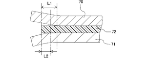
- the lithium-ion secondary battery of the present invention includes a sealing portion between the first current collector and the second current collector in the facing direction. The sealing portion surrounds the positive electrode active material layer and the negative electrode active material layer, and has a function of sealing the electrolytic solution in the space between the first current collector and the second current collector.
- the lithium ion secondary battery of the present invention a storage cell having a positive electrode active material layer, a separator, a negative electrode active material layer and an electrolytic solution between a pair of first and second current collectors. is formed, and the storage cell is separated from the outside world by the seal.
- the lithium ion secondary battery of the present invention may include only one storage cell, or may include a plurality of storage cells.
- the lithium-ion secondary battery of the present invention having the structure described above can reduce the size and weight of the container, and reduce wiring such as lead wires. As a result, the lithium-ion secondary battery of the present invention having the structure described above has an improved energy density per unit volume and weight.
- the lithium ion secondary battery of the present invention having this structure is suitable for being embodied as a cell stack type lithium ion secondary battery, and can have thick electrodes as described above.
- the sealing portion functions as a sealing material for enclosing the electrolytic solution inside the storage cell, and is a spacer for electrically isolating the first current collector and the second current collector that constitute the same storage cell. also functions as The sealing portion that exhibits such a function may have a shape capable of accommodating the positive electrode active material layer and the negative electrode active material layer on the inner peripheral side, specifically, a ring shape or a cylindrical shape.
- the material for the sealing portion a material that can exhibit the above functions may be used, and a resin material is suitable.
- Olefins and acid-modified olefins are suitable as the material for the sealing portion, and specific examples thereof include polyethylene, polypropylene, acid-modified polyethylene, and acid-modified polypropylene.
- the sealing portion is preferably fixed to the first current collector and the second current collector by a general method such as adhesion or welding.
- the electrolyte solution is highly reliably sealed between the first current collector and the second current collector that constitute the same cell, and the relative position of the first current collector and the second current collector and the positive electrode This is for appropriately maintaining the relative positions of the active material layer, the separator, and the negative electrode active material layer.
- the method of fixing the sealing portion to the first current collector and the second current collector is not particularly limited, but methods such as adhesion, welding, and fusion bonding can be exemplified.
- the sealing portion may surround the positive electrode active material layer and the negative electrode active material layer, and may be in contact with or apart from the outer edge portion of the positive electrode active material layer and the outer edge portion of the negative electrode active material layer.
- the sealing portion should be the outer edge of the positive electrode active material layer and the negative electrode active material layer. It is preferably spaced from the outer edge of the material layer.
- a specific method for manufacturing a lithium ion secondary battery will be described.
- a positive electrode in which a positive electrode active material layer is formed on one side of a first current collector and a negative electrode in which a negative electrode active material layer is formed on one side of a second current collector are combined into a positive electrode active material layer and a negative electrode active material layer. face each other through a separator.
- a sealing portion is arranged between the first current collector and the second current collector so as to surround the positive electrode active material layer and the negative electrode active material layer, and the sealing portion serves as the first current collector. adheres to the body and the second current collector.
- the electrolytic solution is sealed inside the sealing portion.
- the first sealing portion is arranged between the first current collector and the separator, and the second sealing portion is arranged between the separator and the second current collector. Then, the first sealing portion and the second sealing portion may be integrated by a method such as adhesion.
- the lithium-ion secondary battery of the present invention may be mounted on a vehicle.
- the vehicle may be any vehicle that uses electrical energy from a lithium-ion secondary battery as a power source in whole or in part, and may be, for example, an electric vehicle or a hybrid vehicle.
- a lithium ion secondary battery is mounted on a vehicle, it is preferable to connect a plurality of lithium ion secondary batteries in series to form an assembled battery.
- Devices equipped with lithium ion secondary batteries include, in addition to vehicles, personal computers, mobile communication devices, various home electric appliances driven by batteries, office equipment, industrial equipment, and the like.
- the lithium ion secondary battery of the present invention is used for wind power generation, solar power generation, hydraulic power generation, and other power storage devices and power smoothing devices for power systems, power sources for ships and/or auxiliary equipment, aircraft, power source for spacecraft and/or auxiliary equipment, auxiliary power source for vehicles that do not use electricity as a power source, power source for mobile home robots, power source for system backup, power source for uninterruptible power supply, It may be used as a power storage device that temporarily stores electric power required for charging in a charging station for an electric vehicle.
- Electrolyte solutions 1 to 3 were prepared by dissolving (FSO 2 ) 2 NLi and LiPF 6 in a mixed solvent of ethylene carbonate and methyl propionate at a volume ratio of 30:70 at the ratios shown in Table 1 below.
- the viscosities of electrolyte solutions 1 to 3 were measured under the following conditions. Table 1 shows the results.
- ⁇ Viscosity> The viscosity of each electrolytic solution was measured at 25° C. with a Brookfield viscometer (Brookfield, DV2T) using a cone-shaped spindle. Note that the rotational speed of the cone-shaped spindle was 60 rpm.
- Electrolytes were produced using propyl propionate, methyl butyrate, and ethyl butyrate as esters with similar chemical structures to methyl propionate, and the effects of these esters on battery characteristics were investigated.
- a mother liquor was prepared by dissolving LiPF 6 at a concentration of 1.2 mol/L in a mixed solvent of ethylene carbonate and methyl propionate at a volume ratio of 15:85.
- LiDFOB Lithium difluoro (oxalate) borate
- LiDFOB is one aspect of oxalate borate) and an amount equivalent to 1% by mass of the mother liquor
- Electrolytic solution 4 was produced by adding and dissolving vinylene carbonate.
- PP ethylene carbonate and propyl propionate
- LiPF6 was dissolved at a concentration of 1.2 mol/L to obtain a mother liquor.
- Electrolytic solution 5 was prepared by adding LiDFOB in an amount corresponding to 1% by mass and vinylene carbonate in an amount corresponding to 1% by mass to the mother liquor and dissolving them.
- LiPF 6 was dissolved at a concentration of 1.2 mol/L in a mixed solvent of ethylene carbonate and methyl butyrate (hereinafter sometimes abbreviated as MB) at a volume ratio of 15:85 to obtain a mother liquor.
- Electrolytic solution 6 was prepared by adding and dissolving LiDFOB in an amount corresponding to 1% by mass and vinylene carbonate in an amount corresponding to 1% by mass with respect to the mother liquor.
- EB a mixed solvent of ethylene carbonate and ethyl butyrate
- Electrolytic solution 7 was prepared by adding LiDFOB in an amount corresponding to 1% by mass and vinylene carbonate in an amount corresponding to 1% by mass to the mother liquor and dissolving them.
- - Ethylene carbonate, ethyl methyl carbonate and dimethyl carbonate were mixed at a volume ratio of 30:30:40 to prepare a mixed solvent.
- LiPF 6 was dissolved in the mixed solvent to prepare a mother liquor having a LiPF 6 concentration of 1 mol/L.
- Electrolytic solution 8 was prepared by adding LiDFOB in an amount corresponding to 0.2 mol/L and vinylene carbonate in an amount corresponding to 1% by mass to the mother liquor and dissolving them.
- LiFePO 4 having an olivine structure coated with carbon as the positive electrode active material, acetylene black as the conductive aid, and polyvinylidene fluoride as the binder, the mass ratio of the positive electrode active material, conductive aid, and binder being 90:5: 5, and N-methyl-2-pyrrolidone was added as a solvent to prepare a composition for forming a positive electrode active material layer in slurry form.
- An aluminum foil was prepared as a positive electrode current collector.
- a positive electrode active material layer is formed on the surface of the aluminum foil by pressing the positive electrode precursor produced by applying the composition for forming the positive electrode active material layer in the form of a film on the surface of the aluminum foil and then removing the solvent, in the thickness direction. was formed on the positive electrode.
- the target weight of the positive electrode was 13.9 mg/cm 2 .
- Graphite as a negative electrode active material, carboxymethyl cellulose and styrene-butadiene rubber as binders were mixed so that the mass ratio of graphite, carboxymethyl cellulose and styrene-butadiene rubber was 97:0.8:2.2, and water was used as a solvent. It was added to prepare a slurry composition for forming a negative electrode active material layer.
- a copper foil was prepared as a current collector for the negative electrode.
- a negative electrode active material layer is formed on the surface of the copper foil by pressing the negative electrode precursor produced by applying the negative electrode active material layer forming composition to the surface of the copper foil in the form of a film and then removing the solvent, in the thickness direction. was formed on the negative electrode.
- the target weight of the negative electrode was 6.3 mg/cm 2 .
- a polypropylene porous membrane was prepared as a separator.
- An electrode body was formed by sandwiching a separator between the positive electrode and the negative electrode.
- the lithium ion secondary battery 4 was manufactured by putting this electrode body together with the electrolytic solution 4 in a bag-like laminate film and sealing it. Lithium ion secondary batteries 5 to 8 were similarly produced using electrolyte solutions 5 to 8.
- Lithium ion secondary batteries 4 to 8 were CC-CV charged to 4.0 V at a rate of 0.4 C, and the charge capacity at this time was used as a reference (SOC 100%).
- a storage test was performed by storing each lithium ion secondary battery at 40° C. for 11 days in the state of SOC 100. Capacity confirmation was performed before and after the storage test. Specifically, CC-CV charging was performed at a rate of 0.4C to 4.0V. Then, CC-CV discharge was performed at a rate of 1C to 2.5V. Thereby, the discharge capacity of each lithium ion secondary battery was confirmed.
- the percentage of the discharge capacity after the storage test to the discharge capacity before the storage test was defined as the capacity retention rate of each lithium ion secondary battery. Further, after the storage test, each lithium ion secondary battery adjusted to SOC 60% was discharged at a constant current rate for 5 seconds at 25° C., and the amount of voltage change was measured. The measurements were performed under multiple conditions with varying current rates. From the obtained results, the constant current (mA) at which the discharge time to a voltage of 2.5 V is 10 seconds was calculated for each lithium ion secondary battery with an SOC of 60%. A value obtained by multiplying the amount of voltage change from SOC 60% to 2.5 V by the calculated constant current was taken as the output. Table 2 shows the results of the above storage test.
- the lithium ion secondary battery 4 using methyl propionate as the non-aqueous solvent of the electrolyte is excellent in both capacity retention rate and output, and in particular in output, carbonate-based non-aqueous solvent It greatly exceeds the lithium ion secondary battery 8 using . This result supports the usefulness of selecting methyl propionate as the non-aqueous solvent.
- Example 1 The electrolytic solution and lithium ion secondary battery of Example 1 are described below.
- the lithium ion secondary battery of Example 1 has a general structure, unlike the lithium ion secondary battery of the present invention described above, except that the electrodes are thick.
- Graphite as a negative electrode active material, and carboxymethyl cellulose and styrene-butadiene rubber as binders were mixed so that the mass ratio of graphite, carboxymethyl cellulose, and styrene-butadiene rubber was 94.8:0.8:4.4.
- Water was added to prepare a slurry composition for forming a negative electrode active material layer.
- a copper foil was prepared as a current collector for the negative electrode.
- a negative electrode active material layer is formed on the surface of the copper foil by pressing the negative electrode precursor produced by applying the negative electrode active material layer forming composition to the surface of the copper foil in the form of a film and then removing the solvent, in the thickness direction. was formed on the negative electrode.
- the weight of the negative electrode was 26.5 mg/cm 2 .
- LiFePO 4 having an olivine structure coated with carbon as the positive electrode active material layer, acetylene black as the conductive aid, and polyvinylidene fluoride as the binder, the mass ratio of the positive electrode active material, conductive aid, and binder being 88.8. :5.1:6.1, and N-methyl-2-pyrrolidone was added as a solvent to prepare a composition for forming a positive electrode active material layer in slurry form.
- An aluminum foil was prepared as a positive electrode current collector.
- a positive electrode active material layer is formed on the surface of the aluminum foil by pressing the positive electrode precursor produced by applying the composition for forming the positive electrode active material layer in the form of a film on the surface of the aluminum foil and then removing the solvent, in the thickness direction. was formed on the positive electrode.
- the basis weight of the positive electrode was 55.5 mg/cm 2 .
- a polypropylene porous membrane was prepared as a separator.
- An electrode body was formed by sandwiching a separator between the positive electrode and the negative electrode.
- the lithium ion secondary battery of Example 1 was manufactured by putting this electrode body together with the electrolytic solution of Example 1 into a bag-like laminate film and sealing it.
- Example 2 The electrolytic solution of Example 2 is the same as the electrolytic solution of Example 1 except for the volume ratio of ethylene carbonate and methyl propionate. Specifically, in Example 2, (FSO 2 ) 2 NLi was dissolved at a concentration of 1.2 mol/L in a mixed solvent in which ethylene carbonate and methyl propionate were mixed at a volume ratio of 25:75, and the mixture was used as the mother liquor. did. An electrolytic solution of Example 2 was produced by adding and dissolving vinylene carbonate in an amount corresponding to 1% by mass with respect to the mother liquor.
- the lithium ion secondary battery of Example 2 is the same as the lithium ion secondary battery of Example 1 except that the electrolyte solution of Example 2 is used.
- Comparative Example 1 The electrolytic solution of Comparative Example 1 is the same as the electrolytic solution of Example 1 except for the volume ratio of ethylene carbonate and methyl propionate. Specifically, in Comparative Example 1, (FSO 2 ) 2 NLi was dissolved at a concentration of 1.2 mol/L in a mixed solvent in which ethylene carbonate and methyl propionate were mixed at a volume ratio of 30:70. did. An electrolytic solution of Comparative Example 1 was produced by adding and dissolving vinylene carbonate in an amount corresponding to 1% by mass with respect to the mother liquor. The lithium ion secondary battery of Comparative Example 1 is the same as the lithium ion secondary battery of Example 1 except that the electrolyte solution of Comparative Example 1 is used.
- Comparative example 2 The electrolytic solution of Comparative Example 2 is the same as the electrolytic solution of Example 1 except for the volume ratio of ethylene carbonate and methyl propionate. Specifically, in Comparative Example 2, (FSO 2 ) 2 NLi was dissolved at a concentration of 1.2 mol/L in a mixed solvent in which ethylene carbonate and methyl propionate were mixed at a volume ratio of 50:50. did. An electrolytic solution of Comparative Example 2 was produced by adding and dissolving vinylene carbonate in an amount corresponding to 1% by mass with respect to the mother liquor. The lithium ion secondary battery of Comparative Example 2 is the same as the lithium ion secondary battery of Example 1 except that the electrolyte solution of Comparative Example 2 is used.
- the lithium-ion secondary batteries of Examples 1 and 2 have all C rates of 0.4C to 4.0C compared to the lithium-ion secondary batteries of Comparative Examples 1 and 2. and exhibits excellent discharge characteristics. This is probably because the electrolyte in the lithium ion secondary batteries of Examples 1 and 2 contained 75% by volume or more of methyl propionate in the non-aqueous solvent.
- the lithium ion secondary battery of Example 1 has a structure different from that of the lithium ion secondary battery of the present invention described above, but needless to say, the effect of the electrolytic solution of Example 1 is the same as that of the lithium ion secondary battery of the present invention. The same effect is exhibited in the next battery. The same applies to each of the following examples.
- Example 3 The electrolytic solution and lithium ion secondary battery of Example 3 are described below.
- [Electrolyte] (FSO 2 ) 2 NLi was dissolved at a concentration of 1.2 mol/L in a mixed solvent of ethylene carbonate and methyl propionate at a volume ratio of 15:85 to obtain a mother liquor.
- 1,3,2-dioxathiolane-2,2-dioxide hereinafter sometimes abbreviated as DTD.
- DTD is one aspect of a cyclic sulfate ester) in an amount equivalent to 0.5% by mass relative to the mother liquor. was added and dissolved to prepare an electrolytic solution of Example 3.
- Graphite as a negative electrode active material, carboxymethyl cellulose and styrene-butadiene rubber as binders were mixed so that the mass ratio of graphite, carboxymethyl cellulose and styrene-butadiene rubber was 97:0.8:2.2, and water was used as a solvent. It was added to prepare a slurry composition for forming a negative electrode active material layer.
- a copper foil was prepared as a current collector for the negative electrode.
- a negative electrode active material layer is formed on the surface of the copper foil by pressing the negative electrode precursor produced by applying the negative electrode active material layer forming composition to the surface of the copper foil in the form of a film and then removing the solvent, in the thickness direction. was formed on the negative electrode.
- the weight of the negative electrode was 6.7 mg/cm 2 .
- LiFePO 4 having an olivine structure coated with carbon as the positive electrode active material layer, acetylene black as the conductive aid, and polyvinylidene fluoride as the binder, the mass ratio of the positive electrode active material, conductive aid and binder being 94:3. : 3, and N-methyl-2-pyrrolidone was added as a solvent to prepare a composition for forming a positive electrode active material layer in slurry form.
- An aluminum foil was prepared as a positive electrode current collector.
- a positive electrode active material layer is formed on the surface of the aluminum foil by pressing the positive electrode precursor produced by applying the composition for forming the positive electrode active material layer in the form of a film on the surface of the aluminum foil and then removing the solvent, in the thickness direction. was formed on the positive electrode.
- the basis weight of the positive electrode was 13.9 mg/cm 2 .
- a lithium-ion secondary battery of Example 3 was manufactured in the same manner as in Example 1 using the above positive electrode and negative electrode.
- Example 4 The electrolytic solution of Example 4 is the same as the electrolytic solution of Example 3 except that (FSO 2 ) 2 NLi and LiPF 6 are used as lithium salts. Specifically, in Example 4, (FSO 2 ) 2 NLi at a concentration of 0.6 mol/L and LiPF 6 at a concentration of 0.6 mol/L were added to a mixed solvent of ethylene carbonate and methyl propionate at a volume ratio of 15:85 It was dissolved at 0.6 mol/L to obtain a mother liquor. An electrolytic solution of Example 4 was produced by adding and dissolving DTD in an amount corresponding to 0.5% by mass with respect to the mother liquor.
- the lithium ion secondary battery of Example 4 is the same as the lithium ion secondary battery of Example 3 except that the electrolyte solution of Example 4 is used.
- Comparative Example 3 The electrolytic solution of Comparative Example 3 is the same as the electrolytic solution of Example 3 except that (FSO 2 ) 2 NLi and LiPF 6 are used as lithium salts. Specifically, in Comparative Example 3, LiPF 6 was dissolved at a concentration of 1.2 mol/L in a mixed solvent of ethylene carbonate and methyl propionate at a volume ratio of 15:85 to obtain a mother liquor. By adding (FSO 2 ) 2 NLi in an amount corresponding to 0.5% by mass and DTD in an amount corresponding to 0.5% by mass to the mother liquor and dissolving, the electrolytic solution of Comparative Example 3 was obtained. manufactured.
- the amount of (FSO 2 ) 2 NLi in the electrolytic solution of Comparative Example 3 was 0.03 mol/L, and the amount of (FSO 2 ) 2 NLi was the sum of (FSO 2 ) 2 NLi and LiPF 6 was 2.4 mol % with respect to
- the lithium ion secondary battery of Comparative Example 3 is the same as the lithium ion secondary battery of Example 3 except that the electrolytic solution of Comparative Example 3 was used.
- Comparative Example 4 The electrolytic solution of Comparative Example 3 is the same as the electrolytic solution of Example 3 except that only LiPF 6 was used as the lithium salt. Specifically, in Comparative Example 3, LiPF 6 was dissolved at a concentration of 1.2 mol/L in a mixed solvent of ethylene carbonate and methyl propionate at a volume ratio of 15:85 to obtain a mother liquor. An electrolytic solution of Comparative Example 4 was produced by adding and dissolving DTD in an amount corresponding to 0.5% by mass with respect to the mother liquor. The lithium ion secondary battery of Comparative Example 4 is the same as the lithium ion secondary battery of Example 3 except that the electrolyte solution of Comparative Example 4 is used.
- each lithium ion secondary battery adjusted to SOC 60% was discharged at a constant current rate for 10 seconds at 25° C., and the amount of change in voltage was measured. The measurements were performed under multiple conditions with varying current rates. From the obtained results, the constant current (mA) at which the discharge time to a voltage of 2.5 V is 10 seconds was calculated for each lithium ion secondary battery with an SOC of 60%. The initial output was obtained by multiplying the amount of voltage change from SOC 60% to 2.5 V by the calculated constant current (mA). Multiple tests of initial output were also performed. The percentage of the output value of each lithium ion secondary battery relative to the output value of the lithium ion secondary battery of Comparative Example 4 was calculated, and the value obtained by subtracting 100 (%) from the percentage was defined as the initial output increase rate (%). .
- Table 4 shows the initial output of each lithium ion secondary battery
- Example 4 compared to the lithium ion secondary battery of Comparative Example 4 in which LiPF 6 was used alone as the lithium salt, Comparative Example 3, Example 3 and Example 3 containing (FSO 2 ) 2 NLi as the lithium salt
- the lithium ion secondary battery of Example 4 is excellent in initial output.
- the (FSO 2 ) 2 NLi content is 30 mol % or more
- the (FSO 2 ) 2 NLi content is less than 30 mol %.
- the initial output is significantly increased.
- the lithium-ion secondary battery of Comparative Example 3 was comparable to Comparative Example 4 in charge-discharge cycle durability at high temperatures.
- the lithium ion secondary batteries of Comparative Examples 3 and 4 were also superior in charge/discharge cycle durability at high temperatures. From these results, (FSO 2 ) 2 NLi, that is, using an electrolytic solution containing 30 mol % or more of a lithium salt other than LiPF 6 with respect to the total lithium salt, the endurance of the lithium ion secondary battery, especially at high temperatures, was improved. It is confirmed that the quality is improved.
- the lithium ion secondary batteries of Examples 3 and 4 are superior to the lithium ion secondary batteries of Comparative Examples 3 and 4 in durability during storage at 40°C. was This result also confirms that the durability of lithium-ion secondary batteries, especially at high temperatures, is improved by using an electrolytic solution containing 30 mol% or more of a lithium salt other than LiPF 6 with respect to the total lithium salt. .
- Example 5 Using the same electrolytic solution of Example 5 as the electrolytic solution of Example 3, a lithium ion secondary battery of Example 5 was manufactured as follows.
- the electrolytic solution of Example 5 was prepared by dissolving (FSO 2 ) 2 NLi at a concentration of 1.2 mol/L in a mixed solvent of ethylene carbonate and methyl propionate at a volume ratio of 15:85. , and DTD in an amount corresponding to 0.5% by mass of the mother liquor is added and dissolved.
- Graphite as a negative electrode active material, carboxymethyl cellulose and styrene-butadiene rubber as binders were mixed so that the mass ratio of graphite, carboxymethyl cellulose and styrene-butadiene rubber was 97:0.8:2.2, and water was used as a solvent. It was added to prepare a slurry composition for forming a negative electrode active material layer.
- a copper foil was prepared as a current collector for the negative electrode.
- a negative electrode active material layer is formed on the surface of the copper foil by pressing the negative electrode precursor produced by applying the negative electrode active material layer forming composition to the surface of the copper foil in the form of a film and then removing the solvent, in the thickness direction. was formed on the negative electrode.
- the weight of the negative electrode was 6.24 mg/cm 2 .
- An aluminum foil was prepared as a positive electrode current collector.
- a positive electrode active material layer is formed on the surface of the aluminum foil by pressing the positive electrode precursor produced by applying the composition for forming the positive electrode active material layer in the form of a film on the surface of the aluminum foil and then removing the solvent, in the thickness direction. was formed on the positive electrode.
- the basis weight of the positive electrode was 13.87 mg/cm 2 .
- a lithium-ion secondary battery of Example 5 was manufactured in the same manner as in Example 1 using the above positive electrode and negative electrode.
- Comparative Example 5 A lithium ion secondary battery of Comparative Example 5 was manufactured in the same manner as in Example 5 using the same electrolytic solution of Comparative Example 5 as the electrolytic solution of Comparative Example 4.
- the electrolytic solution of Comparative Example 5 was prepared by dissolving LiPF 6 at a concentration of 1.2 mol/L in a mixed solvent of ethylene carbonate and methyl propionate at a volume ratio of 15:85 to obtain a mother liquor. DTD was added and dissolved in an amount corresponding to 0.5% by mass with respect to the
- Example 4 Evaluation of gas generation>
- the lithium ion secondary batteries of Example 5 and Comparative Example 5 were activated by charging at 0.05 C to 4.0 V and holding at 60° C. for 20 hours.
- the volume of each lithium ion secondary battery before and after activation was measured by the Archimedes method, and the amount of gas ( ⁇ L) generated by activation was calculated from the volume change of each lithium ion secondary battery before and after activation.
- the amount of gas generated in the lithium ion secondary battery of Example 5 is smaller than that in the lithium ion secondary battery of Comparative Example 5. From this result, it can be seen that gas generated during charging and discharging of the lithium ion secondary battery can be suppressed by using an electrolytic solution containing 30 mol % or more of lithium salt other than LiPF 6 with respect to the total lithium salt. In a lithium ion secondary battery using graphite for the negative electrode, it is considered that gas is generated by decomposition of the electrolytic solution at the negative electrode. In the lithium ion secondary battery of Example 5, (FSO 2 ) 2 NLi contained in the electrolytic solution is decomposed, so that a good film is formed on the surface of the negative electrode.
- Example 6 A lithium ion secondary battery of Example 6 was manufactured in the same manner as in Example 3 using the same electrolyte solution of Example 6 as that of Example 3.
- the electrolytic solution of Example 6 was prepared by dissolving (FSO 2 ) 2 NLi at a concentration of 1.2 mol/L in a mixed solvent of ethylene carbonate and methyl propionate at a volume ratio of 15:85. , and DTD in an amount corresponding to 0.5% by mass of the mother liquor is added and dissolved.
- Example 7 A lithium ion secondary battery of Example 7 was manufactured in the same manner as in Example 3 using the same electrolyte solution of Example 7 as that of Example 4.
- the electrolytic solution of Example 7 was prepared by adding (FSO 2 ) 2 NLi at a concentration of 0.6 mol/L and LiPF 6 to a mixed solvent of ethylene carbonate and methyl propionate at a volume ratio of 15:85. It was dissolved at a concentration of 0.6 mol/L to obtain a mother liquor, and DTD was added and dissolved in an amount corresponding to 0.5% by mass with respect to the mother liquor.
- Comparative Example 6 A lithium ion secondary battery of Comparative Example 6 was manufactured in the same manner as in Example 3 using the same electrolytic solution of Comparative Example 6 as the electrolytic solution of Comparative Example 3.
- the electrolytic solution of Comparative Example 6 was prepared by dissolving LiPF 6 at a concentration of 1.2 mol/L in a mixed solvent of ethylene carbonate and methyl propionate at a volume ratio of 15:85 to obtain a mother liquor.
- FSO 2 ) 2 NLi in an amount corresponding to 0.5% by mass and DTD in an amount corresponding to 0.5% by mass are added and dissolved.
- the amount of (FSO 2 ) 2 NLi in the electrolytic solution of Comparative Example 6 is 0.03 mol/L, and the amount of (FSO 2 ) 2 NLi is the total of (FSO 2 ) 2 NLi and LiPF 6 It was 2.4 mol %.
- Comparative Example 7 A lithium ion secondary battery of Comparative Example 7 was manufactured in the same manner as in Example 3 using the same electrolytic solution of Comparative Example 7 as that of Comparative Example 4.
- the electrolytic solution of Comparative Example 7 was prepared by dissolving LiPF 6 at a concentration of 1.2 mol/L in a mixed solvent of ethylene carbonate and methyl propionate at a volume ratio of 15:85 to obtain a mother liquor. DTD was added and dissolved in an amount corresponding to 0.5% by mass with respect to the
- the lithium ion secondary batteries of Examples 6 and 7 were superior to the lithium ion secondary batteries of Comparative Examples 6 and 7 in capacity retention rate. This result also confirms that the durability of lithium-ion secondary batteries, especially at high temperatures, is improved by using an electrolytic solution containing 30 mol% or more of a lithium salt other than LiPF 6 with respect to the total lithium salt. .
- the lithium ion secondary batteries of Examples 6 and 7 were superior to the lithium ion secondary batteries of Comparative Examples 6 and 7 in capacity retention rate, and after the start of the storage test, The difference was more pronounced as the number of days elapsed was longer. This result also confirms that the durability of lithium-ion secondary batteries, especially at high temperatures, is improved by using an electrolytic solution containing 30 mol% or more of a lithium salt other than LiPF 6 with respect to the total lithium salt. .
- Example 8 (FSO 2 ) 2 NLi was dissolved at a concentration of 1.2 mol/L in a mixed solvent of ethylene carbonate and methyl propionate at a volume ratio of 15:85 to obtain a mother liquor.
- An electrolytic solution of Example 8 was produced by adding and dissolving vinylene carbonate in an amount corresponding to 1.94% by mass with respect to the mother liquor.
- a lithium ion secondary battery of Example 8 was manufactured in the same manner as in Example 1 using the electrolyte solution of Example 8.
- Comparative Example 8 (FSO 2 ) 2 NLi was dissolved at a concentration of 1.2 mol/L in a mixed solvent of ethylene carbonate and dimethyl carbonate at a volume ratio of 15:85 to obtain a mother liquor.
- An electrolytic solution of Comparative Example 8 was produced by adding and dissolving vinylene carbonate in an amount corresponding to 1.94% by mass with respect to the mother liquor.
- a lithium ion secondary battery of Comparative Example 8 was manufactured in the same manner as in Example 1 using the electrolytic solution of Comparative Example 8.
- Comparative Example 9 (FSO 2 ) 2 NLi was dissolved at a concentration of 1.2 mol/L in a mixed solvent of ethylene carbonate, dimethyl carbonate, and ethyl methyl carbonate at a volume ratio of 15:65:20 to obtain a mother liquor.
- An electrolytic solution of Comparative Example 9 was produced by adding and dissolving vinylene carbonate in an amount corresponding to 1.94% by mass with respect to the mother liquor.
- a lithium ion secondary battery of Comparative Example 9 was manufactured in the same manner as in Example 1 using the electrolytic solution of Comparative Example 9.
- Comparative Example 10 (FSO 2 ) 2 NLi was dissolved at a concentration of 1.2 mol/L in a mixed solvent of ethylene carbonate, dimethyl carbonate and ethyl methyl carbonate at a volume ratio of 15:45:40 to obtain a mother liquor.
- An electrolytic solution of Comparative Example 10 was produced by adding and dissolving vinylene carbonate in an amount corresponding to 1.94% by mass with respect to the mother liquor.
- a lithium ion secondary battery of Comparative Example 10 was manufactured in the same manner as in Example 1 using the electrolytic solution of Comparative Example 10.
- Comparative Example 11 A mother liquor was prepared by dissolving LiPF 6 at a concentration of 1.2 mol/L in a mixed solvent in which ethylene carbonate and methyl propionate were mixed at a volume ratio of 15:85.
- An electrolytic solution of Comparative Example 11 was produced by adding and dissolving vinylene carbonate in an amount corresponding to 1% by mass and LiDFOB in an amount corresponding to 1% by mass with respect to the mother liquor.
- a lithium ion secondary battery of Comparative Example 8 was produced in the same manner as in Example 1.
- Example 7 Long-Term Discharge Test 1>
- FIG. 1 is a graph showing changes in CC discharge capacity over time in each of the lithium ion secondary batteries of Example 8 and Comparative Example 11.
- Table 10 shows the rate % of each lithium ion secondary battery of Example 8 and Comparative Example 11.
- the lithium ion secondary battery of Example 8 has a significantly higher capacity at the end of discharge than the ion secondary battery of Comparative Example 11, and can be said to be excellent in long-term discharge characteristics. Further, as shown in Table 10, the lithium ion secondary battery of Example 8 is significantly superior to the lithium ion secondary battery of Comparative Example 11 in rate % at the end of discharge.
- FIG. 2 shows a graph showing changes in CC discharge capacity over time in each of the lithium-ion secondary batteries of Example 8 and Comparative Examples 8-10.
- Table 11 shows the rate % of each lithium ion secondary battery of Example 8 and Comparative Examples 8-10.
- the lithium ion secondary battery of Example 8 has a significantly higher capacity at the end of discharge than the lithium ion secondary batteries of Comparative Examples 8 to 10, and has excellent long-term discharge characteristics. It can be said that there is
- the lithium ion secondary battery of Example 8 is also significantly superior to the lithium ion secondary batteries of Comparative Examples 8 to 10 in terms of rate % at the end of discharge. This result also reveals that the lithium ion secondary battery of Example 8 is excellent in long-term discharge characteristics.
- the reason why the lithium ion secondary battery of Example 8 is superior to the lithium ion secondary batteries of Comparative Examples 8 to 10 in long-term discharge characteristics is considered to be the composition of the non-aqueous electrolyte. This result further clarifies the usefulness of using methyl propionate in the non-aqueous electrolyte. Furthermore, from the results of Evaluation Examples 7 and 8, it was found that by using (FSO 2 ) 2 NLi as a lithium salt in combination with methyl propionate as a non-aqueous solvent, the battery characteristics for a lithium ion secondary battery were improved. It can be said that an electrolytic solution that can contribute to improvement is obtained.
- Example 9 The lithium ion secondary battery of Example 9 is the lithium ion secondary battery of the present invention.
- FIG. 3 shows an explanatory view schematically showing the lithium ion secondary battery of Example 9. As shown in FIG. The lithium ion secondary battery of Example 9 will be described below with reference to FIG.
- the lithium ion secondary battery 1 of Example 9 is obtained by stacking two storage cells 10 .
- Each storage cell 10 has a positive electrode 2 , a negative electrode 3 , a separator 4 , a sealing portion 5 and an electrolytic solution 6 .
- the positive electrode 2 has a first current collector 20 and a positive electrode active material layer 21 .
- the first current collector 20 is an aluminum foil and has one side 20a and the other side 20b.
- the one surface 20a and the other surface 20b are in a back-to-back relationship.
- the positive electrode active material layer 21 is the same as the positive electrode active material layer in the lithium ion secondary battery of Example 1, and is laminated on the central portion of the one surface 20 a of the first current collector 20 .
- the negative electrode 3 has a second current collector 30 and a negative electrode active material layer 31 .
- the second current collector 30 is a copper foil and has one side 30a and the other side 30b. The one surface 30a and the other surface 30b are in a back-to-back relationship.
- the negative electrode active material layer 31 is the same as the negative electrode active material layer in the lithium ion secondary battery of Example 1, and is laminated on the central portion of the one surface 30 a of the second current collector 30 .
- the negative electrode 3 is stacked on the positive electrode 2 in a state in which the negative electrode active material layer 31 faces the positive electrode active material layer 21 and the separator 4 is sandwiched between the negative electrode active material layer 31 and the positive electrode active material layer 21 .
- the negative electrode active material layer 31, the separator 4, and the positive electrode active material layer 21 are arranged between the first current collector 20 and the second current collector 30 that constitute the same storage cell 10 in the facing direction described above. is sandwiched.
- the separator 4 is the same as the separator in the lithium ion secondary battery of Example 1.
- the sealing part 5 is made of acid-modified olefin and has a substantially short cylindrical shape. Between the first current collector 20 and the second current collector 30, the sealing portion 5 is arranged to extend around the laminate of the negative electrode active material layer 31, the separator 4, and the positive electrode active material layer 21 in the circumferential direction of the laminate. It surrounds all around. The surface of the sealing portion 5 on the side of the first current collector 20 is heat-sealed to the first current collector 20, and the surface on the side of the second current collector 30 is heat-sealed to the second current collector 30. ing. Thereby, the sealing portion 5 liquid-tightly seals between the first current collector 20 and the second current collector 30 . The sealing portion 5 also functions as a spacer for maintaining the distance between the first current collector 20 and the second current collector 30 and breaking the direct electrical connection between the two.
- the electrolytic solution 6 is sealed in the space defined by the sealing portion 5 , the first current collector 20 and the second current collector 30 .
- the electrolytic solution 6 is the same as the electrolytic solution of the first embodiment.
- the lithium-ion secondary battery 1 of Example 9 has two storage cells 10 connected in series. Also, the first current collector 20x of one storage cell 10x and the second current collector 30y of the adjacent storage cell 10y are overlapped and directly electrically connected. Therefore, the first current collector 20x and the second current collector 30y can be regarded as one current collector having a two-layer structure, and the current collector has a cathode active material layer 21x on each of both surfaces thereof. and the negative electrode active material layer 31y can be regarded as a bipolar electrode.
- the positive electrode 2 and the negative electrode 3 are manufactured by the method described in Example 1.
- the sealing portion 5 is integrated with one of the positive electrode 2 and the negative electrode 3 .
- the sealing portion 5 is heat-sealed to one of the first current collector 20 and the second current collector 30 using an impulse sealing machine.
- the sealing portion 5 is integrated with the first current collector 20 or the second current collector 30 in a box shape, and the electrolytic solution 6 can be accommodated therein.
- the electrolytic solution 6 is injected into the inside of the sealing portion 5, and the other of the positive electrode 2 and the negative electrode 3 is integrated with this.
- the positive electrode active material layer 21 and the negative electrode active material layer 31 face each other and are stacked while sandwiching the separator 4 and the sealing portion 5 therebetween. Then, the sealing portion 5 is heat-sealed to the other of the first current collector 20 and the second current collector 30 using an impulse sealing machine.
- the storage cell 10 in the lithium ion secondary battery 1 of Example 9 was obtained. Two storage cells 10 are prepared, and a first current collector 20x of the first storage cell 10x, which is one of the storage cells 10, and a second current collector 30y of the second storage cell 10y, which is the other of the storage cells 10. are superimposed in the facing direction to stack the first current collector 20x and the second current collector 30y.
- the two stacked storage cells 10 are restrained by a restraining member (not shown), and a predetermined restraining load is applied to each storage cell 10 in the facing direction. Thereby, the first storage cell 10x and the second storage cell 10y can be maintained in a stacked state. Further, terminals (not shown) are fixed to the storage cells 10x and 10y. Thus, a lithium ion secondary battery of Example 9 was obtained.
- the sealing portion 5 is fixed to the first current collector 20 and the second current collector 30 . Therefore, each storage cell 10 can stably hold the electrolytic solution 6 therein.
- the lithium ion secondary battery of Example 10 is the lithium ion secondary battery of the present invention, and is substantially the same as the lithium ion secondary battery of Example 9 except for the structures of the first current collector and the second current collector. be.
- FIG. 4 is an explanatory view schematically showing the lithium ion secondary battery of Example 10. As shown in FIG. The lithium ion secondary battery of Example 10 will be described below with reference to FIG.
- the first current collector 20 of the positive electrode 2 and the second current collector 30 of the negative electrode 3 in the lithium ion secondary battery of Example 10 are integrally formed.
- the first current collector 20 is an aluminum foil
- the second current collector 30 is a copper-plated layer formed on the first current collector 20 .
- the lithium ion secondary battery of Example 10 also has excellent durability.
- Example 11 An electrolytic solution of Example 11 was prepared by dissolving (FSO 2 ) 2 NLi at a concentration of 1.2 mol/L in a mixed solvent of ethylene carbonate and methyl propionate at a volume ratio of 30:70.
- Example 12 (FSO 2 ) 2 NLi at a concentration of 1 mol/L and LiPF 6 at a concentration of 0.2 mol/L were dissolved in a mixed solvent in which ethylene carbonate and methyl propionate were mixed at a volume ratio of 30:70. A liquid was produced.
- the amount of (FSO 2 ) 2 NLi with respect to the total lithium salt is about 83.3 mol %.
- Example 13 (FSO 2 ) 2 NLi at a concentration of 0.8 mol/L and LiPF 6 at a concentration of 0.4 mol/L were dissolved in a mixed solvent of ethylene carbonate and methyl propionate at a volume ratio of 30:70. was manufactured.
- the amount of (FSO 2 ) 2 NLi with respect to the total lithium salt is about 66.7 mol %.
- Example 14 (FSO 2 ) 2 NLi at a concentration of 0.6 mol/L and LiPF 6 at a concentration of 0.6 mol/L were dissolved in a mixed solvent of ethylene carbonate and methyl propionate at a volume ratio of 30:70. was manufactured.
- the amount of (FSO 2 ) 2 NLi with respect to the total lithium salt is about 50 mol %.
- Example 15 (FSO 2 ) 2 NLi at a concentration of 0.4 mol/L and LiPF 6 at a concentration of 0.8 mol/L were dissolved in a mixed solvent of ethylene carbonate and methyl propionate at a volume ratio of 30:70. was manufactured.
- the amount of (FSO 2 ) 2 NLi with respect to the total lithium salt is about 33.3 mol %.
- Comparative Example 13 An electrolytic solution of Comparative Example 13 was prepared by dissolving LiPF 6 at a concentration of 1.2 mol/L in a mixed solvent of ethylene carbonate and methyl propionate at a volume ratio of 30:70.
- a test piece was prepared by heat-sealing an aluminum foil and a copper foil with a sealing material.
- the test piece was immersed in each of the electrolytic solutions of Examples 11 to 15 and Comparative Examples 12 and 13 to evaluate peeling.
- the dimensions of each test piece were 15 mm x 65 mm and the seal width was 18 mm.
- the sealing material is an acid-modified olefin-based material, and more specifically contains polyethylene resin with a low melting point.
- An impulse sealer was used for heat sealing, and the heating temperature was 110°C.
- An aluminum laminate film was made into a bag shape of 60 mm ⁇ 100 mm, 1 mL of electrolytic solution was injected into the bag, and a test piece was immersed therein.
- test piece and the electrolytic solution were sealed inside the bag. This was stored at 60°C for 72 hours. After that, the test piece taken out of the bag was washed with ethanol, and the natural peel length generated on the test piece was measured. A groove micrometer was used for the measurement.
- the length from the starting point of peeling between the resin 72 and the aluminum foil 70 to the terminal end of the resin 72 is defined as the natural peeling length L1 at the interface between the aluminum foil 70 and the resin 72 .
- the length from the starting point of peeling between the resin 72 and the copper foil 71 to the terminal end of the resin 72 was defined as the natural peeling length L2 at the interface between the copper foil 71 and the resin 72 .
- L1 and L2 were measured at a plurality of points, the average was calculated, and this was used as the natural peel length of the test piece for each electrolytic solution. The results are shown in FIG.
Landscapes
- Chemical & Material Sciences (AREA)
- Engineering & Computer Science (AREA)
- General Chemical & Material Sciences (AREA)
- Chemical Kinetics & Catalysis (AREA)
- Electrochemistry (AREA)
- Manufacturing & Machinery (AREA)
- Inorganic Chemistry (AREA)
- General Physics & Mathematics (AREA)
- Condensed Matter Physics & Semiconductors (AREA)
- Physics & Mathematics (AREA)
- Materials Engineering (AREA)
- Secondary Cells (AREA)
- Sealing Battery Cases Or Jackets (AREA)
- Battery Electrode And Active Subsutance (AREA)
Priority Applications (4)
| Application Number | Priority Date | Filing Date | Title |
|---|---|---|---|
| CN202280026650.6A CN117099238A (zh) | 2021-03-29 | 2022-01-18 | 电解液和锂离子二次电池 |
| US18/284,376 US20240170725A1 (en) | 2021-03-29 | 2022-01-18 | Electrolytic solution and lithium ion secondary battery |
| EP22779390.8A EP4318718A4 (en) | 2021-03-29 | 2022-01-18 | LITHIUM-ION ELECTROLYTIC SOLUTION AND SECONDARY BATTERY |
| KR1020237020273A KR20230109691A (ko) | 2021-03-29 | 2022-01-18 | 전해액 및 리튬 이온 이차 전지 |
Applications Claiming Priority (2)
| Application Number | Priority Date | Filing Date | Title |
|---|---|---|---|
| JP2021-056292 | 2021-03-29 | ||
| JP2021056292A JP7563273B2 (ja) | 2021-03-29 | 2021-03-29 | 電解液およびリチウムイオン二次電池 |
Publications (1)
| Publication Number | Publication Date |
|---|---|
| WO2022209158A1 true WO2022209158A1 (ja) | 2022-10-06 |
Family
ID=83458585
Family Applications (1)
| Application Number | Title | Priority Date | Filing Date |
|---|---|---|---|
| PCT/JP2022/001511 WO2022209158A1 (ja) | 2021-03-29 | 2022-01-18 | 電解液およびリチウムイオン二次電池 |
Country Status (6)
Families Citing this family (2)
| Publication number | Priority date | Publication date | Assignee | Title |
|---|---|---|---|---|
| US12237492B2 (en) * | 2022-03-07 | 2025-02-25 | The University Of Hong Kong | Flexible and printable paper-based Al ion batteries |
| WO2024184682A1 (en) * | 2023-03-08 | 2024-09-12 | Ses Holdings Pte. Ltd. | Electrolytes containing sulfonamide-type cyclic salts, and energy-storage cells and batteries made therewith |
Citations (8)
| Publication number | Priority date | Publication date | Assignee | Title |
|---|---|---|---|---|
| JP2008258022A (ja) * | 2007-04-05 | 2008-10-23 | Bridgestone Corp | 電池用非水電解液及びそれを備えた非水電解液電池 |
| JP2010123300A (ja) | 2008-11-17 | 2010-06-03 | Toyota Central R&D Labs Inc | リチウム二次電池及びその使用方法 |
| JP2013140734A (ja) | 2012-01-05 | 2013-07-18 | Gs Yuasa Corp | 非水電解質二次電池 |
| JP2015201318A (ja) | 2014-04-07 | 2015-11-12 | トヨタ自動車株式会社 | 電極シートの製造方法 |
| JP2018092785A (ja) * | 2016-12-02 | 2018-06-14 | 日本電気株式会社 | リチウムイオン二次電池用電解液およびリチウムイオン二次電池 |
| WO2018179884A1 (ja) * | 2017-03-30 | 2018-10-04 | パナソニックIpマネジメント株式会社 | 非水電解液及び非水電解液二次電池 |
| JP2020026926A (ja) | 2018-08-13 | 2020-02-20 | 株式会社フジクラ | 熱交換器及び磁気ヒートポンプ装置 |
| JP2021003409A (ja) | 2019-06-27 | 2021-01-14 | 株式会社三洋物産 | 遊技機 |
Family Cites Families (1)
| Publication number | Priority date | Publication date | Assignee | Title |
|---|---|---|---|---|
| KR101233325B1 (ko) * | 2011-04-11 | 2013-02-14 | 로베르트 보쉬 게엠베하 | 리튬 이차 전지용 전해액 및 이를 포함하는 리튬 이차 전지 |
-
2021
- 2021-03-29 JP JP2021056292A patent/JP7563273B2/ja active Active
-
2022
- 2022-01-18 CN CN202280026650.6A patent/CN117099238A/zh active Pending
- 2022-01-18 WO PCT/JP2022/001511 patent/WO2022209158A1/ja active Application Filing
- 2022-01-18 KR KR1020237020273A patent/KR20230109691A/ko active Pending
- 2022-01-18 US US18/284,376 patent/US20240170725A1/en active Pending
- 2022-01-18 EP EP22779390.8A patent/EP4318718A4/en active Pending
Patent Citations (8)
| Publication number | Priority date | Publication date | Assignee | Title |
|---|---|---|---|---|
| JP2008258022A (ja) * | 2007-04-05 | 2008-10-23 | Bridgestone Corp | 電池用非水電解液及びそれを備えた非水電解液電池 |
| JP2010123300A (ja) | 2008-11-17 | 2010-06-03 | Toyota Central R&D Labs Inc | リチウム二次電池及びその使用方法 |
| JP2013140734A (ja) | 2012-01-05 | 2013-07-18 | Gs Yuasa Corp | 非水電解質二次電池 |
| JP2015201318A (ja) | 2014-04-07 | 2015-11-12 | トヨタ自動車株式会社 | 電極シートの製造方法 |
| JP2018092785A (ja) * | 2016-12-02 | 2018-06-14 | 日本電気株式会社 | リチウムイオン二次電池用電解液およびリチウムイオン二次電池 |
| WO2018179884A1 (ja) * | 2017-03-30 | 2018-10-04 | パナソニックIpマネジメント株式会社 | 非水電解液及び非水電解液二次電池 |
| JP2020026926A (ja) | 2018-08-13 | 2020-02-20 | 株式会社フジクラ | 熱交換器及び磁気ヒートポンプ装置 |
| JP2021003409A (ja) | 2019-06-27 | 2021-01-14 | 株式会社三洋物産 | 遊技機 |
Non-Patent Citations (1)
| Title |
|---|
| See also references of EP4318718A4 |
Also Published As
| Publication number | Publication date |
|---|---|
| JP7563273B2 (ja) | 2024-10-08 |
| US20240170725A1 (en) | 2024-05-23 |
| JP2022153187A (ja) | 2022-10-12 |
| EP4318718A1 (en) | 2024-02-07 |
| EP4318718A4 (en) | 2025-07-09 |
| KR20230109691A (ko) | 2023-07-20 |
| CN117099238A (zh) | 2023-11-21 |
Similar Documents
| Publication | Publication Date | Title |
|---|---|---|
| JP7232359B2 (ja) | 再充電可能なバッテリーセル用のso2ベースの電解質および再充電可能なバッテリーセル | |
| JP7268796B2 (ja) | リチウムイオン二次電池 | |
| JP6070540B2 (ja) | 二次電池および電解液 | |
| WO2017094416A1 (ja) | リチウム二次電池用正極活物質、リチウム二次電池用正極及びリチウム二次電池、並びにそれらの製造方法 | |
| JP6801722B2 (ja) | 二次電池、電池パック、電動車両、電力貯蔵システム、電動工具および電子機器 | |
| JP6623464B2 (ja) | リチウムイオン二次電池 | |
| JP7003394B2 (ja) | 二次電池用電解液、二次電池、電池パック、電動車両、電力貯蔵システム、電動工具および電子機器 | |
| JP6279233B2 (ja) | リチウム二次電池 | |
| JP6680293B2 (ja) | ハイドロフルオロエーテル化合物、非水電解液およびリチウムイオン二次電池 | |
| CN110036521B (zh) | 锂离子二次电池 | |
| JP7565624B2 (ja) | リチウム2次電池 | |
| JPWO2015080102A1 (ja) | 二次電池用電解液およびこれを用いた二次電池 | |
| CN115485903B (zh) | 二次电池用电解液添加剂、包含所述添加剂的二次电池用非水电解液及二次电池 | |
| CN107836061A (zh) | 非水电解质电池及电池包 | |
| WO2022209158A1 (ja) | 電解液およびリチウムイオン二次電池 | |
| KR20160055137A (ko) | 이차 전지 | |
| JP6177042B2 (ja) | リチウム二次電池 | |
| WO2023042262A1 (ja) | リチウム2次電池 | |
| JP5582573B2 (ja) | 二次電池およびそれに用いる二次電池用電解液 | |
| WO2022254717A1 (ja) | リチウム2次電池 | |
| JP2016207447A (ja) | 非水電解液二次電池 | |
| KR20230137979A (ko) | 충전식 배터리 셀 | |
| JPWO2012029645A1 (ja) | 二次電池およびそれに用いる二次電池用電解液 | |
| CN116438692B (zh) | 锂二次电池 | |
| WO2023053295A1 (ja) | リチウム2次電池 |
Legal Events
| Date | Code | Title | Description |
|---|---|---|---|
| 121 | Ep: the epo has been informed by wipo that ep was designated in this application |
Ref document number: 22779390 Country of ref document: EP Kind code of ref document: A1 |
|
| ENP | Entry into the national phase |
Ref document number: 20237020273 Country of ref document: KR Kind code of ref document: A |
|
| WWE | Wipo information: entry into national phase |
Ref document number: 18284376 Country of ref document: US |
|
| WWE | Wipo information: entry into national phase |
Ref document number: 202280026650.6 Country of ref document: CN |
|
| WWE | Wipo information: entry into national phase |
Ref document number: 202317068347 Country of ref document: IN |
|
| WWE | Wipo information: entry into national phase |
Ref document number: 2022779390 Country of ref document: EP |
|
| NENP | Non-entry into the national phase |
Ref country code: DE |
|
| ENP | Entry into the national phase |
Ref document number: 2022779390 Country of ref document: EP Effective date: 20231030 |