WO2022180769A1 - Matériau de noyau pour échantillon commercial et échantillon commercial - Google Patents
Matériau de noyau pour échantillon commercial et échantillon commercial Download PDFInfo
- Publication number
- WO2022180769A1 WO2022180769A1 PCT/JP2021/007276 JP2021007276W WO2022180769A1 WO 2022180769 A1 WO2022180769 A1 WO 2022180769A1 JP 2021007276 W JP2021007276 W JP 2021007276W WO 2022180769 A1 WO2022180769 A1 WO 2022180769A1
- Authority
- WO
- WIPO (PCT)
- Prior art keywords
- side plate
- core material
- bottom plate
- state
- product sample
- Prior art date
Links
- 239000011162 core material Substances 0.000 title claims abstract description 102
- 230000000452 restraining effect Effects 0.000 claims description 8
- 238000004806 packaging method and process Methods 0.000 description 8
- 238000010586 diagram Methods 0.000 description 6
- 230000002093 peripheral effect Effects 0.000 description 6
- 238000000034 method Methods 0.000 description 4
- 239000007788 liquid Substances 0.000 description 3
- 239000000463 material Substances 0.000 description 3
- 238000012986 modification Methods 0.000 description 3
- 230000004048 modification Effects 0.000 description 3
- 230000001788 irregular Effects 0.000 description 2
- 239000011347 resin Substances 0.000 description 2
- 229920005989 resin Polymers 0.000 description 2
- 230000000717 retained effect Effects 0.000 description 1
- 239000007787 solid Substances 0.000 description 1
- 230000037303 wrinkles Effects 0.000 description 1
Images


Classifications
-
- B—PERFORMING OPERATIONS; TRANSPORTING
- B65—CONVEYING; PACKING; STORING; HANDLING THIN OR FILAMENTARY MATERIAL
- B65D—CONTAINERS FOR STORAGE OR TRANSPORT OF ARTICLES OR MATERIALS, e.g. BAGS, BARRELS, BOTTLES, BOXES, CANS, CARTONS, CRATES, DRUMS, JARS, TANKS, HOPPERS, FORWARDING CONTAINERS; ACCESSORIES, CLOSURES, OR FITTINGS THEREFOR; PACKAGING ELEMENTS; PACKAGES
- B65D33/00—Details of, or accessories for, sacks or bags
- B65D33/02—Local reinforcements or stiffening inserts, e.g. wires, strings, strips or frames
Definitions
- This disclosure relates to core materials for product samples and product samples.
- a packaging bag for packaging a content such as a liquid a self-supporting packaging bag called a stand pack is known (see, for example, Patent Document 1, etc.). Since it can stand on its own in the folded state, there is an advantage that the visibility is enhanced when merchandise is displayed.
- the surface of the packaging bag is printed with the name, description, photograph, etc. of the product.
- the method of attaching a sample sheet to the surface of an existing packaging bag takes time to attach the sheet, and the attached sheet may wrinkle, resulting in poor appearance of the product sample. Sometimes.
- the purpose of the present disclosure is to configure a stand-up pack product sample so that it can be created with a simple work and look good, and to configure the stand-up pack product sample so that it can be easily transported. do.
- a core material for a product sample is a core material used to configure a product sample of a stand pack, and has a first side plate, a second side plate, and a bottom plate in series, and is in an unfolded state. and assembled state.
- the unfolded state is a state in which the first side plate, the second side plate and the bottom plate are unfolded into a plane
- the assembled state is the state in which the first side plate and the second side plate are placed through the bottom plate, It is a state in which they are held in a state of being swollen outward.
- a product sample according to one aspect of the present disclosure includes the core material and a bag into which the core material is inserted.
- the bag is a bag in which a pair of sheets are attached together.
- FIG. 1 is a diagram showing an unfolded state of a core material used for a product sample according to the first embodiment.
- FIG. 2 is a diagram showing the middle of assembly of the core material of the same.
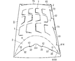
- FIG. 3 is a diagram showing an assembled state of the core material of the same.
- FIG. 4 is a diagram showing a bag used for the product sample same as the above.
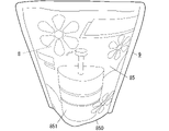
- FIG. 5 is a perspective view of the same product sample.
- FIG. 6 is a diagram showing an unfolded state of the core material used for the product sample of the second embodiment.
- FIG. 7 is a diagram showing side by side the core material and the bag used for the same product sample.
- FIG. 5 shows a product sample 9 of the first embodiment.
- Product sample 9 is a sample of a self-supporting packaging bag called a stand pack.
- the product sample 9 is constructed by inserting the assembled core material 8 shown in FIG. 3 into the bag 85 shown in FIG.
- the vertical, horizontal, and horizontal directions used in the following description are based on when the product sample 9 is made to stand on its own.
- the core member 8 can be switched between the unfolded state shown in FIG. 1 and the assembled state shown in FIG. By three-dimensionally assembling the core material 8 in the unfolded state according to a predetermined procedure, the core material 8 is switched from the unfolded state to the assembled state. Further, by unfolding the core material 8 in the assembled state in accordance with a predetermined procedure, the core material 8 is switched from the assembled state to the unfolded state.
- the core material 8 is made of paper (specifically, cardboard) so that it can be repeatedly folded.
- the core material 8 is formed by processing one sheet of paper.
- the core member 8 includes a first side plate 1 having a rectangular outer shape, a second side plate 2 having an outer shape in which a part of the rectangular shape is recessed in an arc, and a spindle-like outer shape. It has a bottom plate 3 with a series.
- the first side plate 1 has a rectangular outer shape with the first direction D1 as its longitudinal direction.
- a short direction of the first side plate 1 is a second direction D2 orthogonal to the first direction D1.
- the first side plate 1 is provided so as to be connected to the second side plate 2 on the same plane in the unfolded state.
- a linear folding line 5 extending in the vertical direction is provided.
- one side sandwiching the folding line 5 is the first side plate 1, and the other side is the second side plate 2.
- the folding line 5 is a line that marks the valley fold.
- the first side plate 1 has a plurality of holes 12 for hooking a portion 31 of the bottom plate 3 in the assembled state.
- the plurality of holes 12 are four holes 12 arranged in the lower portion of the first side plate 1 .
- the array of the four holes 12 is an arcuate array that bulges upward.
- four holes 12 each having a rectangular shape constitute the portion 11 on which the portion 31 of the bottom plate 3 is hooked.
- the first side plate 1 has a plurality of cuts 7 for creating irregularities on the side surface of the core material 8 in the assembled state.
- the plurality of cuts 7 are arranged at a distance from each other in a portion of the first side plate 1 above the portion of the first side plate 1 where the plurality of holes 12 are provided (that is, the lower portion of the first side plate 1).
- Each notch 7 has a polygonal line shape obtained by removing the lower base from the trapezoid.
- Each incision 7 is non-linear and non-circular.
- the arrangement of the plurality of incisions 7 is a regular arrangement vertically and horizontally, but the arrangement is not limited to this, and the arrangement of the plurality of incisions 7 may be an irregular arrangement.
- the plurality of cuts 7 have the same size and shape as each other, but at least one of the plurality of cuts 7 may have a different size from the remaining cuts 7.
- at least one of the plurality of incisions 7 may have a different shape than the remaining incisions 7, or at least one of the plurality of incisions 7 may have a different dimensional shape than the remaining incisions 7. good too. Modifications of the shape that the cut 7 can have will be described later.
- At least one of the plurality of incisions 7 is arranged in a direction different from that of the remaining incisions 7. Specifically, it is arranged in a plurality of vertical rows (specifically, 3 rows). Among the plurality of incisions 7 formed, the plurality of incisions 7 arranged in at least one row (specifically, one row in the middle of the three rows) is arranged in the opposite direction to the plurality of incisions 7 in the remaining rows Although arranged, all of the plurality of incisions 7 may be arranged in the same orientation. Further, in the first embodiment, the plurality of cuts 7 are arranged in three vertical rows, but may be arranged in one or two vertical rows, or may be four or more rows.
- the first side plate 1 is provided with a plurality of projecting pieces 61 and 62 projecting away from the folding line 5 .
- the plurality of protruding pieces 61 and 62 are two protruding pieces 61 and 62 positioned vertically side by side.
- the projecting piece 61 located on the lower side has a hook-shaped hooking piece 611 that constitutes the distal end portion of the projecting piece 61 and a connecting piece 612 that constitutes the proximal end portion of the projecting piece 61.
- the hooking piece 611 has portions 6112 and 6114 that protrude upward and downward from the portion of the connecting piece 612 connected to the hooking piece 611 .
- a part of the connecting piece 612 is composed of a restraining piece 614 .
- the restraining piece 614 constitutes the lower part of the connecting piece 612 and has an inclined side 6141 that is inclined so that the farther away from the hooking piece 611, the lower it is.
- the inclined side 6141 is a linear lower end side of the connecting piece 612 .
- the upper end side of the connecting piece 612 is a straight side extending in the horizontal direction.
- the projecting piece 62 located on the upper side has a hook-shaped hooking piece 621 that constitutes the distal end portion of the projecting piece 62 and a connecting piece 622 that constitutes the proximal end portion of the projecting piece 62.
- the hooking piece 621 has portions 6212 and 6214 that protrude upward and downward from the portion of the connecting piece 622 connected to the hooking piece 621 .
- the upper end side and the lower end side of the connecting piece 622 are straight sides parallel to each other.
- the hooking piece 621 included in the upper projecting piece 62 has a smaller vertical dimension than the hooking piece 611 included in the lower projecting piece 61 .
- the first side plate 1 is provided with a protruding piece 63 protruding from the top of the first side plate 1 .
- the projecting piece 63 includes a hook-shaped hooking piece 631 forming the distal end portion of the projecting piece 63 and a connecting piece 632 forming the proximal end portion of the projecting piece 63 .
- the hooking piece 631 has portions 6312 and 6314 that protrude to both the left and right sides from the portion of the connecting piece 632 connected to the hooking piece 631 .
- the left and right edges of the connecting piece 632 are slanted sides that are slanted so that the closer they are to the first side plate 1 , the farther away they are from each other.
- the second side plate 2 is formed so as to be continuous with the first side plate 1 in the second direction D2.
- the second side plate 2 has a rectangular outer shape with a longitudinal direction in the first direction D1 and a lateral direction in the second direction D2.
- the second side plate 2 like the first side plate 1, has a plurality of non-linear cuts 7 for creating unevenness on the side surface of the core material 8 in the assembled state.
- a plurality of incisions 7 are arranged at a distance from each other.
- the arrangement of the plurality of cuts 7 is a regular arrangement vertically and horizontally, but the arrangement is not limited to this, and the arrangement of the plurality of cuts 7 may be irregular.
- the plurality of cuts 7 have the same size and shape, but at least one of the plurality of cuts 7 may have a size and shape different from the remaining cuts 7 .
- at least one of the plurality of cuts 7 is arranged in a direction different from that of the remaining cuts 7 (specifically, the plurality of cuts 7 arranged in three vertical rows).
- the plurality of incisions 7 arranged in the middle row are arranged in the opposite direction to the plurality of incisions 7 in the remaining rows), but the plurality of incisions 7 are all arranged in the same direction. good too.
- a plurality of holes 71 and 72 are provided in the end portion of the second side plate 2 away from the folding line 5 .
- the plurality of holes 71 and 72 are two holes 71 and 72 positioned vertically side by side.
- the two holes 71 and 72 are formed by straight cuts vertically.
- the lower hole 71 is a hole into which the lower protruding piece 61 provided on the first side plate 1 is inserted
- the upper hole 72 is a hole into which the upper protruding piece 62 provided on the first side plate 1 is inserted. It is a hole to be inserted.
- the upper hole 72 has a smaller vertical dimension than the lower hole 71 . In other words, the length of the upper hole 72 in the vertical direction is shorter than the length of the lower hole 71 in the vertical direction.
- a hole 73 is provided in the upper end portion of the second side plate 2 (specifically, the portion of the second side plate 2 above the portion in which the plurality of cuts 7 are provided).
- the hole 73 is a hole into which the protruding piece 63 provided on the first side plate 1 is inserted, and is formed by straight cuts left and right.
- the bottom plate 3 has a spindle-shaped outer shape whose longitudinal direction is the second direction D2, and is formed so as to be continuous with the second side plate 2 in the first direction D1.
- the longitudinal direction of the spindle-shaped bottom plate 3 is, in other words, the axial direction of the bottom plate 3 .
- the bottom plate 3 is connected to the second side plate 2 via an arc-shaped folding line 4 .
- the side plate 2 that is directly connected to the bottom plate 3 is the second side plate 2
- the side plate 1 that is not directly connected to the bottom plate 3 is the first side plate 1 .
- the folding line 4 is an arc-shaped folding line that bulges upward.
- the folding line 4 is a line having the function of a valley fold mark and a guide, and is composed of a plurality of holes arranged in an arc shape.
- a recess 351 is provided in the central portion of the peripheral edge 35 that swells toward the side opposite to the side where the folding line 4 swells.
- the recess 351 is a semicircular recess.
- a plurality of protrusions 32 are provided on the peripheral edge 35 .
- the arrangement of the plurality of protrusions 32 is an arcuate arrangement that expands toward the side opposite to the side where the folding line 4 expands.
- the plurality of protrusions 32 are four protrusions 32 configured to be inserted into the four holes 12 arranged in the first side plate 1 in a one-to-one relationship.
- Four protrusions 32 form part 31 of the bottom plate 3 that is inserted into the four holes 12 .
- the bag 85 is a bag formed by bonding a pair of sheets 851 and 852 together.
- the pair of sheets 851 and 852 are flexible sheets made of resin or paper, for example.
- the pair of sheets 851 and 852 On the surfaces of the pair of sheets 851 and 852, letters, figures, photographs, symbols, etc. related to the product are appropriately printed.
- the pair of sheets 851 and 852 are adhered together at their peripheral edges except for their lower ends. Therefore, the bottom end 850 of the bag 85 is open, and the assembled core material 8 can be inserted into the bag 85 through the opening.
- the unfolded state of the core material 8 is, as shown in FIG. 1, a state in which the first side plate 1, the second side plate 2, and the bottom plate 3 formed using one sheet of paper are unfolded flat.
- the entire core material 8 is folded in half along the folding line 5, the first side plate 1 and the second side plate 2 are overlapped, and then the three parts provided on the first side plate 1 are folded.
- the projecting pieces 61, 62, 63 are inserted into the corresponding holes 71, 72, 73 of the second side plate 2, respectively.
- the protruding pieces 61, 62, 63 are caught in the corresponding holes 71, 72, 73, respectively, and the core member 8 is in the state of being assembled as shown in FIG.
- the bottom plate 3 is folded perpendicularly to the second side plate 2 along the arc-shaped folding lines 4, and the four projections 32 provided on the bottom plate 3 are inserted into the corresponding holes 12 of the first side plate 1, respectively. enter.
- the user can operate the bottom plate 3 while inserting his or her finger into the recess 351 of the bottom plate 3 .
- the core member 8 is brought into the assembled state shown in FIG.
- the first side plate 1 and the second side plate 2 are held in a state of being bulged outward via the bottom plate 3 positioned between them.
- the bottom plate 3 is held in an arch-like shape that bulges upward.
- Each of the first side plate 1 and the second side plate 2 swells with a large curvature toward the outer side in a portion closer to the bottom plate 3. - ⁇ Therefore, the assembled core material 8 has a shape similar to an actual stand pack.
- the bottom plate 3 is interposed between the lower portion of the first side plate 1 and the lower portion of the second side plate.
- a relatively large force acts to
- the lower projecting piece 61 includes a restraining piece 614, and the restraining piece 614 restrains the part of the second side plate 2 that is most likely to be lifted from the first side plate 1. is effectively suppressed.
- the product sample 9 shown in FIG. 5 is obtained.
- the shape similar to the actual stand pack is obtained by the core material 8 inserted inside.
- fine unevenness is created on the side surface by the unevenness on the side surface of the core material 8 created by the plurality of cuts 7 .
- Actual stand packs in which viscous liquid contents or solid contents are packaged generally have fine unevenness on the side surface.
- a shape more closely resembling an actual stand pack is obtained.
- the user After using the product sample 9, the user removes the protruding pieces 61, 62, 63 from the corresponding holes 71, 72, 73 while the core material 8 is still inserted into the bag 85. 2 can be returned to the thin state (state in the middle of assembly). Thereby, the user can compactly store the product sample 9 while the core material 8 is inserted into the bag 85 .
- the product sample 9 When the product sample 9 is to be reused, the user operates the bottom plate 3 with a finger while the core material 8 is inserted into the bag 85, so that the core material 8 can be returned to the assembled state with one touch. can be done. In other words, when the user repeatedly uses the product sample 9, the user can switch between three-dimensional and thin product samples 9 with one touch while the core material 8 is inserted into the bag 85. ⁇
- (Second embodiment) 6 and 7 show product samples 9 of the second embodiment.
- components having the same functions as in the first embodiment are denoted by the same reference numerals, and detailed description thereof is omitted.
- a product sample 9 of the second embodiment is a stand-up pack sample with a spout.
- An inclined side 15 inclined by about 45° with respect to the folding line 5 is provided at the upper corner portion of the first side plate 1 on the side away from the folding line 5 .
- an inclined side 25 inclined by about 45° with respect to the folding line 5 is provided at the upper corner portion of the second side plate 2 away from the folding line 5 .
- the inclined side 15 of the first side plate 1 and the inclined side 25 of the second side plate 2 are configured to overlap each other in the assembled state.
- a projecting portion 855 imitating a spout is provided at the upper corner of the bag 85 .
- the projecting portion 855 is included in the bonded portion of the pair of sheets 851 and 852 .
- the projecting portion 855 of the bag 85 is closest to the inclined side 15 of the first side plate 1 and the inclined side 25 of the second side plate 2. located.
- the surface of the bag 85 can be appropriately printed with characters, figures, photographs, symbols, etc. related to the product.
- the material of the core material 8 (that is, the material of the first side plate 1, the second side plate 2, the bottom plate 3, and the projecting pieces 61, 62, 63) is not limited to paper, and may be resin or the like as long as it can be repeatedly folded. It is also possible to use the material of
- the plurality of nonlinear cuts 7 may be provided only on the first side plate 1 or may be provided only on the second side plate 2 .
- the shape of each notch 7 may be other shapes such as an arc shape, a wavy shape, or an appropriate broken line shape that is broken at least at one point.
- the polygonal shape here is, for example, a triangle with one side removed (in other words, a polygonal shape that is bent at one point), or a rectangle with one side removed (in other words, a polygonal line that is bent at two points at right angles). etc.
- the first side plate 1 may have only one hole 12 and the bottom plate 3 may have only one projection 32 inserted into the hole 12 .
- one hole 12 constitutes the portion 11 of the first side plate 1 and one projection 32 constitutes the portion 31 of the bottom plate 3 .
- the second side plate 2 may have a projecting piece 61 projecting away from the folding line 5, and the first side plate 1 may have a hole 71 into which the projecting piece 61 is inserted.
- the second side plate 2 may have a projecting piece 62 projecting away from the folding line 5, and the first side plate 1 may have a hole 72 into which the projecting piece 62 is inserted.
- the second side plate 2 may have the protrusion 63 and the first side plate 1 may have the hole 73 .
- a plurality of projecting pieces 61 including the pressing piece 614 may be provided, or the projecting piece 61 may not include the pressing piece 614 . Also, a plurality of protrusions 63 and holes 73 may be provided.
- the folding lines 4 may be composed of solid lines, dashed lines, chain lines, or dotted lines, or may be composed of discontinuous or continuous grooves.
- the folding lines 5 need only be composed of lines that serve as marks, and may be composed of any of solid lines, dashed lines, chain lines, and dotted lines. Moreover, the folding line 5 may be composed of a linear groove, or may be composed of a plurality of discontinuous grooves or holes.
- the shape of the bottom plate 3 is not limited to the spindle shape, and may be other shapes such as an ellipse and a perfect circle.
- the core material (8) for the product sample of the first aspect of the present disclosure is used to configure the product sample (9) of the stand pack.
- a core member (8) comprising a first side plate (1), a second side plate (2) and a bottom plate (3) in series and switchable between an unfolded state and an assembled state.
- the unfolded state is a state in which the first side plate (1), the second side plate (2) and the bottom plate (3) are unfolded flat.
- the assembled state is a state in which the first side plate (1) and the second side plate (2) are held in a state of bulging outward through the bottom plate (3).
- the core material (8) for the product sample of the first aspect is switched from the unfolded state to the assembled state, and the core material (8) in the assembled state is covered with the bag (85).
- a product sample (9) of a stand pack can be produced with good appearance by simple work.
- the core material (8) can be returned to a thin state. Therefore, it becomes possible to easily transport the product sample (9) in the stand-up pack and to store the product sample (9) in the stand-up pack easily.
- the core material (8) for product samples of the second aspect of the present disclosure further comprises the following configuration in the first aspect.
- the bottom plate (3) is in one piece with the second side plate (2).
- the first side plate (1) has a portion (11) on which a part (31) of the bottom plate (3) is hooked in the assembled state.
- the bottom plate (3) is bent with respect to the second side plate (2), and a part (31) of the bottom plate (3) is bent to the first side plate (1). ), the core material (8) for constructing the product sample (9) of the stand pack can be assembled.
- the core material (8) for product samples of the third aspect of the present disclosure further comprises the following configuration in the second aspect.
- the part (31) of the bottom plate (3) consists of at least one prong (61).
- a portion (11) of the first side plate (1) is configured with at least one hole (12) into which at least one projection (61) is inserted in the assembled state.
- the bottom plate (3) is bent with respect to the second side plate (2), and at least one protrusion (32) of the bottom plate (3) is attached to the first
- a core material (8) for constructing a product sample (9) of a stand pack can be assembled by a simple operation of inserting it into at least one hole (12) of the side plate (1).
- the core material (8) for product samples of the fourth aspect of the present disclosure further comprises the following configuration in the second or third aspects.
- the bottom plate (3) and the second side plate (2) are connected together via an arc-shaped folding line (4).
- the first side plate (1) and the second side plate (2) are held in a curved state. Through the bottom plate (3), they can be stably held in a state of being swollen outward.
- the core material (8) for product samples of the fifth aspect of the present disclosure further comprises the following configuration in the second aspect.
- the bottom plate (3) and the second side plate (2) are connected together via an arc-shaped folding line (4).
- a part (31) of the bottom plate (3) consists of a plurality of protrusions (32).
- a portion (11) of the first side plate (1) is composed of a plurality of holes (12) arranged in an arc. In the assembled state, the projections (32) are inserted into the holes (12) respectively.
- the bottom plate (3) is bent with respect to the second side plate (2), and the plurality of projections (32) of the bottom plate (3) are attached to the first side plate.
- the core material (8) can be assembled by a simple work of inserting it into each of the plurality of holes (12) of (1).
- the first side plate (1) and the second side plate (2) are stably bulging outward via the bottom plate (3) held in a curved state. retained.
- the core material (8) for product samples of the sixth aspect of the present disclosure further comprises the following configuration in any one of the first to fifth aspects.
- the first side plate (1) and the second side plate (2) are connected together via a straight folding line (5).
- One of the first side plate (1) and the second side plate (2) is provided with a projecting piece (61) that protrudes away from the straight folding line (5).
- the other of the first side plate (1) and the second side plate (2) is provided with a hole (12) into which the projecting piece (61) is inserted in the assembled state.
- the unfolded core material (8) is folded in two along the straight folding line (5), and the protrusion (61) is inserted into the hole (12).
- the core material (8) can be assembled by a simple operation of inserting.
- the core material (8) for product samples of the seventh aspect of the present disclosure further comprises the following configuration in the sixth aspect.
- the projecting piece (61) is composed of a hooking piece (611) that constitutes the distal end portion of the projecting piece (61) and a restraining piece (614) that constitutes part of the proximal end portion of the projecting piece (61). ) and
- the restraining piece (614) has an inclined side (6141) which is inclined so that the farther it is from the hooking piece (611), the lower it is located.
- the hook (611) can prevent the projecting piece (61) from coming out of the hole (12), and the restraining piece (614)
- the shape of the core material (8) in the assembled state can be stably maintained.
- the core material (8) for product samples of the eighth aspect of the present disclosure further comprises the following configuration in any one of the first to seventh aspects.
- both or one of the first side plate (1) and the second side plate (2) are provided with a plurality of non-linear cuts (7).
- both or one of the first side plate (1) and the second side plate (2) has each The portion near the cut (7) protrudes further outward than the other portions, thereby making it possible to create irregularities on the side surface of the core material (8).
- the core material (8) for product samples of the ninth aspect of the present disclosure further comprises the following configuration in any one of the first to eighth aspects.
- the first side plate (1), the second side plate (2) and the bottom plate (3) are made of paper.
- the unfolded state and assembled state of the core material (8) can be repeatedly switched.
- the core material (8) can be made lightweight and can be provided at a low cost.
- a product sample (9) of the tenth aspect of the present disclosure comprises the core material (8) of any one of the first to ninth aspects and a bag (85) into which the core material (8) is inserted.
- a bag (85) is a bag in which a pair of sheets (851, 852) are stuck together.
- the core material (8) is switched from the unfolded state to the assembled state, and the core material (8) in the assembled state is covered with the bag (85).
- the product sample (9) of the stand pack can be created with good appearance.
- the core material (8) can be returned to a thin state with the core material (8) inserted into the bag (85). Therefore, it becomes possible to easily transport the product sample (9) in the stand-up pack and to store the product sample (9) in the stand-up pack easily.
Landscapes
- Engineering & Computer Science (AREA)
- Mechanical Engineering (AREA)
- Packages (AREA)
Abstract
Un échantillon commercial de stand pack est configuré de façon à pouvoir être créé avec un bel aspect par une opération facile. Un matériau de noyau 8 pour un échantillon commercial est utilisé pour configurer un échantillon commercial de stand pack. Le matériau de noyau 8 a une première plaque latérale 1, une seconde plaque latérale 2 et une plaque inférieure 3 disposées successivement et est commutable entre un état développé et un état assemblé. L'état développé est un état dans lequel la première plaque latérale 1, la seconde plaque latérale 2 et la plaque inférieure 3 sont développées selon une forme plane. L'état assemblé est un état dans lequel chacune des première plaque latérale 1 et seconde plaque latérale 2 est maintenue dans un état d'expansion vers l'extérieur par l'intermédiaire de la plaque inférieure 3.
Priority Applications (3)
| Application Number | Priority Date | Filing Date | Title |
|---|---|---|---|
| PCT/JP2021/007276 WO2022180769A1 (fr) | 2021-02-26 | 2021-02-26 | Matériau de noyau pour échantillon commercial et échantillon commercial |
| CN202180004354.1A CN115298104B (zh) | 2021-02-26 | 2021-02-26 | 用于商业样品的芯材料及商业样品 |
| JP2021577983A JP7236175B2 (ja) | 2021-02-26 | 2021-02-26 | 商品サンプル用の芯材及び商品サンプル |
Applications Claiming Priority (1)
| Application Number | Priority Date | Filing Date | Title |
|---|---|---|---|
| PCT/JP2021/007276 WO2022180769A1 (fr) | 2021-02-26 | 2021-02-26 | Matériau de noyau pour échantillon commercial et échantillon commercial |
Publications (1)
| Publication Number | Publication Date |
|---|---|
| WO2022180769A1 true WO2022180769A1 (fr) | 2022-09-01 |
Family
ID=83048940
Family Applications (1)
| Application Number | Title | Priority Date | Filing Date |
|---|---|---|---|
| PCT/JP2021/007276 WO2022180769A1 (fr) | 2021-02-26 | 2021-02-26 | Matériau de noyau pour échantillon commercial et échantillon commercial |
Country Status (3)
| Country | Link |
|---|---|
| JP (1) | JP7236175B2 (fr) |
| CN (1) | CN115298104B (fr) |
| WO (1) | WO2022180769A1 (fr) |
Citations (4)
| Publication number | Priority date | Publication date | Assignee | Title |
|---|---|---|---|---|
| JPH0468836U (fr) * | 1990-10-26 | 1992-06-18 | ||
| JP2005280753A (ja) * | 2004-03-29 | 2005-10-13 | Fuji Seal International Inc | 包装容器 |
| US20050252811A1 (en) * | 2002-05-16 | 2005-11-17 | Cristalid Sa | Display package and shaping device therefor |
| EP1714893A1 (fr) * | 2005-04-18 | 2006-10-25 | L'Oreal-D.I.P.I. | Emballage pour le conditionnement d'un objet |
Family Cites Families (14)
| Publication number | Priority date | Publication date | Assignee | Title |
|---|---|---|---|---|
| US5400906A (en) * | 1994-04-21 | 1995-03-28 | Tang; Hin M. | Bag having expanding means therein |
| US5897084A (en) * | 1998-04-06 | 1999-04-27 | Judge; John A. | Folding trash bag expanding form and holder |
| JP3643750B2 (ja) * | 2000-03-21 | 2005-04-27 | 凸版印刷株式会社 | パウチ用包装体 |
| US20050178931A1 (en) * | 2001-01-12 | 2005-08-18 | Tom Tomlin | Trash bag support and liner |
| US20080251654A1 (en) * | 2007-04-13 | 2008-10-16 | Sharon Campbell | Support structure for a limp bag |
| JP5209421B2 (ja) * | 2008-09-10 | 2013-06-12 | 株式会社フジシールインターナショナル | 物品収容ケース |
| US20110226914A1 (en) * | 2010-03-20 | 2011-09-22 | Instabol LLC | Collapsible support structure for a bag |
| US20120219241A1 (en) * | 2011-02-24 | 2012-08-30 | Rodney Horton | Storage bag expansion insert |
| US20130051705A1 (en) * | 2011-08-22 | 2013-02-28 | Inga-Lill Amoroso | Convertible gift bag to gift box |
| JP2013086876A (ja) * | 2011-10-20 | 2013-05-13 | Eemon:Kk | 物品等の収容ケース |
| CA2792963A1 (fr) * | 2012-10-16 | 2014-04-16 | Maxime Laberge | Support pour sac a feuilles |
| US10232970B2 (en) * | 2013-04-23 | 2019-03-19 | ProAmpac Intermediate, Inc. | Hold-open device and package having same |
| JP2015163513A (ja) * | 2014-02-28 | 2015-09-10 | 菱江産業株式会社 | ケース組み立て用シート、包装ケース及び包装体 |
| JP2018062383A (ja) * | 2016-10-16 | 2018-04-19 | 株式会社エーモン | 物品等の収容ケース |
-
2021
- 2021-02-26 JP JP2021577983A patent/JP7236175B2/ja active Active
- 2021-02-26 WO PCT/JP2021/007276 patent/WO2022180769A1/fr active Application Filing
- 2021-02-26 CN CN202180004354.1A patent/CN115298104B/zh active Active
Patent Citations (4)
| Publication number | Priority date | Publication date | Assignee | Title |
|---|---|---|---|---|
| JPH0468836U (fr) * | 1990-10-26 | 1992-06-18 | ||
| US20050252811A1 (en) * | 2002-05-16 | 2005-11-17 | Cristalid Sa | Display package and shaping device therefor |
| JP2005280753A (ja) * | 2004-03-29 | 2005-10-13 | Fuji Seal International Inc | 包装容器 |
| EP1714893A1 (fr) * | 2005-04-18 | 2006-10-25 | L'Oreal-D.I.P.I. | Emballage pour le conditionnement d'un objet |
Also Published As
| Publication number | Publication date |
|---|---|
| CN115298104B (zh) | 2024-04-26 |
| CN115298104A (zh) | 2022-11-04 |
| JPWO2022180769A1 (fr) | 2022-09-01 |
| JP7236175B2 (ja) | 2023-03-09 |
Similar Documents
| Publication | Publication Date | Title |
|---|---|---|
| WO2022180769A1 (fr) | Matériau de noyau pour échantillon commercial et échantillon commercial | |
| JP2010116183A (ja) | ケース | |
| JP2003137271A (ja) | 収納箱 | |
| KR200406265Y1 (ko) | 접이식 종이 상자 | |
| JP3243449U (ja) | 包装容器 | |
| JP3066659U (ja) | 容 器 | |
| JP2018024451A (ja) | 可変箱 | |
| JP6929571B2 (ja) | 梱包具および梱包方法 | |
| JP2011184107A (ja) | 衝撃緩和運搬容器 | |
| JP2005104549A (ja) | 紙製収納箱 | |
| JPH082152Y2 (ja) | 巻糸体梱包用ボビンホルダー | |
| JP2004345721A (ja) | 紙製包装容器 | |
| JP4136631B2 (ja) | 紙箱 | |
| JP2007320566A (ja) | 立上片付ケース | |
| JP3063919U (ja) | 容 器 | |
| JP3677184B2 (ja) | オブラート支持容器 | |
| JP5008935B2 (ja) | 円筒状物品の保持ケース | |
| JP3157012U (ja) | 包装箱 | |
| JP3155293U (ja) | パレット用収容容器 | |
| JPH09295670A (ja) | 簡易包装具 | |
| JP3078666U (ja) | 容 器 | |
| JPH0562461U (ja) | 外装ケース | |
| JP2020001729A (ja) | 包装用箱 | |
| JP2008285197A (ja) | 収納ケース | |
| KR20110133818A (ko) | 포장용 상자 구조 |
Legal Events
| Date | Code | Title | Description |
|---|---|---|---|
| ENP | Entry into the national phase |
Ref document number: 2021577983 Country of ref document: JP Kind code of ref document: A |
|
| 121 | Ep: the epo has been informed by wipo that ep was designated in this application |
Ref document number: 21927871 Country of ref document: EP Kind code of ref document: A1 |
|
| NENP | Non-entry into the national phase |
Ref country code: DE |
|
| 122 | Ep: pct application non-entry in european phase |
Ref document number: 21927871 Country of ref document: EP Kind code of ref document: A1 |