WO2022180769A1 - Core material for commercial sample and commercial sample - Google Patents
Core material for commercial sample and commercial sample Download PDFInfo
- Publication number
- WO2022180769A1 WO2022180769A1 PCT/JP2021/007276 JP2021007276W WO2022180769A1 WO 2022180769 A1 WO2022180769 A1 WO 2022180769A1 JP 2021007276 W JP2021007276 W JP 2021007276W WO 2022180769 A1 WO2022180769 A1 WO 2022180769A1
- Authority
- WO
- WIPO (PCT)
- Prior art keywords
- side plate
- core material
- bottom plate
- state
- product sample
- Prior art date
Links
- 239000011162 core material Substances 0.000 title claims abstract description 102
- 230000000452 restraining effect Effects 0.000 claims description 8
- 238000004806 packaging method and process Methods 0.000 description 8
- 238000010586 diagram Methods 0.000 description 6
- 230000002093 peripheral effect Effects 0.000 description 6
- 238000000034 method Methods 0.000 description 4
- 239000007788 liquid Substances 0.000 description 3
- 239000000463 material Substances 0.000 description 3
- 238000012986 modification Methods 0.000 description 3
- 230000004048 modification Effects 0.000 description 3
- 230000001788 irregular Effects 0.000 description 2
- 239000011347 resin Substances 0.000 description 2
- 229920005989 resin Polymers 0.000 description 2
- 230000000717 retained effect Effects 0.000 description 1
- 239000007787 solid Substances 0.000 description 1
- 230000037303 wrinkles Effects 0.000 description 1
Images


Classifications
-
- B—PERFORMING OPERATIONS; TRANSPORTING
- B65—CONVEYING; PACKING; STORING; HANDLING THIN OR FILAMENTARY MATERIAL
- B65D—CONTAINERS FOR STORAGE OR TRANSPORT OF ARTICLES OR MATERIALS, e.g. BAGS, BARRELS, BOTTLES, BOXES, CANS, CARTONS, CRATES, DRUMS, JARS, TANKS, HOPPERS, FORWARDING CONTAINERS; ACCESSORIES, CLOSURES, OR FITTINGS THEREFOR; PACKAGING ELEMENTS; PACKAGES
- B65D33/00—Details of, or accessories for, sacks or bags
- B65D33/02—Local reinforcements or stiffening inserts, e.g. wires, strings, strips or frames
Definitions
- This disclosure relates to core materials for product samples and product samples.
- a packaging bag for packaging a content such as a liquid a self-supporting packaging bag called a stand pack is known (see, for example, Patent Document 1, etc.). Since it can stand on its own in the folded state, there is an advantage that the visibility is enhanced when merchandise is displayed.
- the surface of the packaging bag is printed with the name, description, photograph, etc. of the product.
- the method of attaching a sample sheet to the surface of an existing packaging bag takes time to attach the sheet, and the attached sheet may wrinkle, resulting in poor appearance of the product sample. Sometimes.
- the purpose of the present disclosure is to configure a stand-up pack product sample so that it can be created with a simple work and look good, and to configure the stand-up pack product sample so that it can be easily transported. do.
- a core material for a product sample is a core material used to configure a product sample of a stand pack, and has a first side plate, a second side plate, and a bottom plate in series, and is in an unfolded state. and assembled state.
- the unfolded state is a state in which the first side plate, the second side plate and the bottom plate are unfolded into a plane
- the assembled state is the state in which the first side plate and the second side plate are placed through the bottom plate, It is a state in which they are held in a state of being swollen outward.
- a product sample according to one aspect of the present disclosure includes the core material and a bag into which the core material is inserted.
- the bag is a bag in which a pair of sheets are attached together.
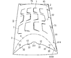
- FIG. 1 is a diagram showing an unfolded state of a core material used for a product sample according to the first embodiment.
- FIG. 2 is a diagram showing the middle of assembly of the core material of the same.
- FIG. 3 is a diagram showing an assembled state of the core material of the same.
- FIG. 4 is a diagram showing a bag used for the product sample same as the above.
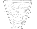
- FIG. 5 is a perspective view of the same product sample.
- FIG. 6 is a diagram showing an unfolded state of the core material used for the product sample of the second embodiment.
- FIG. 7 is a diagram showing side by side the core material and the bag used for the same product sample.
- FIG. 5 shows a product sample 9 of the first embodiment.
- Product sample 9 is a sample of a self-supporting packaging bag called a stand pack.
- the product sample 9 is constructed by inserting the assembled core material 8 shown in FIG. 3 into the bag 85 shown in FIG.
- the vertical, horizontal, and horizontal directions used in the following description are based on when the product sample 9 is made to stand on its own.
- the core member 8 can be switched between the unfolded state shown in FIG. 1 and the assembled state shown in FIG. By three-dimensionally assembling the core material 8 in the unfolded state according to a predetermined procedure, the core material 8 is switched from the unfolded state to the assembled state. Further, by unfolding the core material 8 in the assembled state in accordance with a predetermined procedure, the core material 8 is switched from the assembled state to the unfolded state.
- the core material 8 is made of paper (specifically, cardboard) so that it can be repeatedly folded.
- the core material 8 is formed by processing one sheet of paper.
- the core member 8 includes a first side plate 1 having a rectangular outer shape, a second side plate 2 having an outer shape in which a part of the rectangular shape is recessed in an arc, and a spindle-like outer shape. It has a bottom plate 3 with a series.
- the first side plate 1 has a rectangular outer shape with the first direction D1 as its longitudinal direction.
- a short direction of the first side plate 1 is a second direction D2 orthogonal to the first direction D1.
- the first side plate 1 is provided so as to be connected to the second side plate 2 on the same plane in the unfolded state.
- a linear folding line 5 extending in the vertical direction is provided.
- one side sandwiching the folding line 5 is the first side plate 1, and the other side is the second side plate 2.
- the folding line 5 is a line that marks the valley fold.
- the first side plate 1 has a plurality of holes 12 for hooking a portion 31 of the bottom plate 3 in the assembled state.
- the plurality of holes 12 are four holes 12 arranged in the lower portion of the first side plate 1 .
- the array of the four holes 12 is an arcuate array that bulges upward.
- four holes 12 each having a rectangular shape constitute the portion 11 on which the portion 31 of the bottom plate 3 is hooked.
- the first side plate 1 has a plurality of cuts 7 for creating irregularities on the side surface of the core material 8 in the assembled state.
- the plurality of cuts 7 are arranged at a distance from each other in a portion of the first side plate 1 above the portion of the first side plate 1 where the plurality of holes 12 are provided (that is, the lower portion of the first side plate 1).
- Each notch 7 has a polygonal line shape obtained by removing the lower base from the trapezoid.
- Each incision 7 is non-linear and non-circular.
- the arrangement of the plurality of incisions 7 is a regular arrangement vertically and horizontally, but the arrangement is not limited to this, and the arrangement of the plurality of incisions 7 may be an irregular arrangement.
- the plurality of cuts 7 have the same size and shape as each other, but at least one of the plurality of cuts 7 may have a different size from the remaining cuts 7.
- at least one of the plurality of incisions 7 may have a different shape than the remaining incisions 7, or at least one of the plurality of incisions 7 may have a different dimensional shape than the remaining incisions 7. good too. Modifications of the shape that the cut 7 can have will be described later.
- At least one of the plurality of incisions 7 is arranged in a direction different from that of the remaining incisions 7. Specifically, it is arranged in a plurality of vertical rows (specifically, 3 rows). Among the plurality of incisions 7 formed, the plurality of incisions 7 arranged in at least one row (specifically, one row in the middle of the three rows) is arranged in the opposite direction to the plurality of incisions 7 in the remaining rows Although arranged, all of the plurality of incisions 7 may be arranged in the same orientation. Further, in the first embodiment, the plurality of cuts 7 are arranged in three vertical rows, but may be arranged in one or two vertical rows, or may be four or more rows.
- the first side plate 1 is provided with a plurality of projecting pieces 61 and 62 projecting away from the folding line 5 .
- the plurality of protruding pieces 61 and 62 are two protruding pieces 61 and 62 positioned vertically side by side.
- the projecting piece 61 located on the lower side has a hook-shaped hooking piece 611 that constitutes the distal end portion of the projecting piece 61 and a connecting piece 612 that constitutes the proximal end portion of the projecting piece 61.
- the hooking piece 611 has portions 6112 and 6114 that protrude upward and downward from the portion of the connecting piece 612 connected to the hooking piece 611 .
- a part of the connecting piece 612 is composed of a restraining piece 614 .
- the restraining piece 614 constitutes the lower part of the connecting piece 612 and has an inclined side 6141 that is inclined so that the farther away from the hooking piece 611, the lower it is.
- the inclined side 6141 is a linear lower end side of the connecting piece 612 .
- the upper end side of the connecting piece 612 is a straight side extending in the horizontal direction.
- the projecting piece 62 located on the upper side has a hook-shaped hooking piece 621 that constitutes the distal end portion of the projecting piece 62 and a connecting piece 622 that constitutes the proximal end portion of the projecting piece 62.
- the hooking piece 621 has portions 6212 and 6214 that protrude upward and downward from the portion of the connecting piece 622 connected to the hooking piece 621 .
- the upper end side and the lower end side of the connecting piece 622 are straight sides parallel to each other.
- the hooking piece 621 included in the upper projecting piece 62 has a smaller vertical dimension than the hooking piece 611 included in the lower projecting piece 61 .
- the first side plate 1 is provided with a protruding piece 63 protruding from the top of the first side plate 1 .
- the projecting piece 63 includes a hook-shaped hooking piece 631 forming the distal end portion of the projecting piece 63 and a connecting piece 632 forming the proximal end portion of the projecting piece 63 .
- the hooking piece 631 has portions 6312 and 6314 that protrude to both the left and right sides from the portion of the connecting piece 632 connected to the hooking piece 631 .
- the left and right edges of the connecting piece 632 are slanted sides that are slanted so that the closer they are to the first side plate 1 , the farther away they are from each other.
- the second side plate 2 is formed so as to be continuous with the first side plate 1 in the second direction D2.
- the second side plate 2 has a rectangular outer shape with a longitudinal direction in the first direction D1 and a lateral direction in the second direction D2.
- the second side plate 2 like the first side plate 1, has a plurality of non-linear cuts 7 for creating unevenness on the side surface of the core material 8 in the assembled state.
- a plurality of incisions 7 are arranged at a distance from each other.
- the arrangement of the plurality of cuts 7 is a regular arrangement vertically and horizontally, but the arrangement is not limited to this, and the arrangement of the plurality of cuts 7 may be irregular.
- the plurality of cuts 7 have the same size and shape, but at least one of the plurality of cuts 7 may have a size and shape different from the remaining cuts 7 .
- at least one of the plurality of cuts 7 is arranged in a direction different from that of the remaining cuts 7 (specifically, the plurality of cuts 7 arranged in three vertical rows).
- the plurality of incisions 7 arranged in the middle row are arranged in the opposite direction to the plurality of incisions 7 in the remaining rows), but the plurality of incisions 7 are all arranged in the same direction. good too.
- a plurality of holes 71 and 72 are provided in the end portion of the second side plate 2 away from the folding line 5 .
- the plurality of holes 71 and 72 are two holes 71 and 72 positioned vertically side by side.
- the two holes 71 and 72 are formed by straight cuts vertically.
- the lower hole 71 is a hole into which the lower protruding piece 61 provided on the first side plate 1 is inserted
- the upper hole 72 is a hole into which the upper protruding piece 62 provided on the first side plate 1 is inserted. It is a hole to be inserted.
- the upper hole 72 has a smaller vertical dimension than the lower hole 71 . In other words, the length of the upper hole 72 in the vertical direction is shorter than the length of the lower hole 71 in the vertical direction.
- a hole 73 is provided in the upper end portion of the second side plate 2 (specifically, the portion of the second side plate 2 above the portion in which the plurality of cuts 7 are provided).
- the hole 73 is a hole into which the protruding piece 63 provided on the first side plate 1 is inserted, and is formed by straight cuts left and right.
- the bottom plate 3 has a spindle-shaped outer shape whose longitudinal direction is the second direction D2, and is formed so as to be continuous with the second side plate 2 in the first direction D1.
- the longitudinal direction of the spindle-shaped bottom plate 3 is, in other words, the axial direction of the bottom plate 3 .
- the bottom plate 3 is connected to the second side plate 2 via an arc-shaped folding line 4 .
- the side plate 2 that is directly connected to the bottom plate 3 is the second side plate 2
- the side plate 1 that is not directly connected to the bottom plate 3 is the first side plate 1 .
- the folding line 4 is an arc-shaped folding line that bulges upward.
- the folding line 4 is a line having the function of a valley fold mark and a guide, and is composed of a plurality of holes arranged in an arc shape.
- a recess 351 is provided in the central portion of the peripheral edge 35 that swells toward the side opposite to the side where the folding line 4 swells.
- the recess 351 is a semicircular recess.
- a plurality of protrusions 32 are provided on the peripheral edge 35 .
- the arrangement of the plurality of protrusions 32 is an arcuate arrangement that expands toward the side opposite to the side where the folding line 4 expands.
- the plurality of protrusions 32 are four protrusions 32 configured to be inserted into the four holes 12 arranged in the first side plate 1 in a one-to-one relationship.
- Four protrusions 32 form part 31 of the bottom plate 3 that is inserted into the four holes 12 .
- the bag 85 is a bag formed by bonding a pair of sheets 851 and 852 together.
- the pair of sheets 851 and 852 are flexible sheets made of resin or paper, for example.
- the pair of sheets 851 and 852 On the surfaces of the pair of sheets 851 and 852, letters, figures, photographs, symbols, etc. related to the product are appropriately printed.
- the pair of sheets 851 and 852 are adhered together at their peripheral edges except for their lower ends. Therefore, the bottom end 850 of the bag 85 is open, and the assembled core material 8 can be inserted into the bag 85 through the opening.
- the unfolded state of the core material 8 is, as shown in FIG. 1, a state in which the first side plate 1, the second side plate 2, and the bottom plate 3 formed using one sheet of paper are unfolded flat.
- the entire core material 8 is folded in half along the folding line 5, the first side plate 1 and the second side plate 2 are overlapped, and then the three parts provided on the first side plate 1 are folded.
- the projecting pieces 61, 62, 63 are inserted into the corresponding holes 71, 72, 73 of the second side plate 2, respectively.
- the protruding pieces 61, 62, 63 are caught in the corresponding holes 71, 72, 73, respectively, and the core member 8 is in the state of being assembled as shown in FIG.
- the bottom plate 3 is folded perpendicularly to the second side plate 2 along the arc-shaped folding lines 4, and the four projections 32 provided on the bottom plate 3 are inserted into the corresponding holes 12 of the first side plate 1, respectively. enter.
- the user can operate the bottom plate 3 while inserting his or her finger into the recess 351 of the bottom plate 3 .
- the core member 8 is brought into the assembled state shown in FIG.
- the first side plate 1 and the second side plate 2 are held in a state of being bulged outward via the bottom plate 3 positioned between them.
- the bottom plate 3 is held in an arch-like shape that bulges upward.
- Each of the first side plate 1 and the second side plate 2 swells with a large curvature toward the outer side in a portion closer to the bottom plate 3. - ⁇ Therefore, the assembled core material 8 has a shape similar to an actual stand pack.
- the bottom plate 3 is interposed between the lower portion of the first side plate 1 and the lower portion of the second side plate.
- a relatively large force acts to
- the lower projecting piece 61 includes a restraining piece 614, and the restraining piece 614 restrains the part of the second side plate 2 that is most likely to be lifted from the first side plate 1. is effectively suppressed.
- the product sample 9 shown in FIG. 5 is obtained.
- the shape similar to the actual stand pack is obtained by the core material 8 inserted inside.
- fine unevenness is created on the side surface by the unevenness on the side surface of the core material 8 created by the plurality of cuts 7 .
- Actual stand packs in which viscous liquid contents or solid contents are packaged generally have fine unevenness on the side surface.
- a shape more closely resembling an actual stand pack is obtained.
- the user After using the product sample 9, the user removes the protruding pieces 61, 62, 63 from the corresponding holes 71, 72, 73 while the core material 8 is still inserted into the bag 85. 2 can be returned to the thin state (state in the middle of assembly). Thereby, the user can compactly store the product sample 9 while the core material 8 is inserted into the bag 85 .
- the product sample 9 When the product sample 9 is to be reused, the user operates the bottom plate 3 with a finger while the core material 8 is inserted into the bag 85, so that the core material 8 can be returned to the assembled state with one touch. can be done. In other words, when the user repeatedly uses the product sample 9, the user can switch between three-dimensional and thin product samples 9 with one touch while the core material 8 is inserted into the bag 85. ⁇
- (Second embodiment) 6 and 7 show product samples 9 of the second embodiment.
- components having the same functions as in the first embodiment are denoted by the same reference numerals, and detailed description thereof is omitted.
- a product sample 9 of the second embodiment is a stand-up pack sample with a spout.
- An inclined side 15 inclined by about 45° with respect to the folding line 5 is provided at the upper corner portion of the first side plate 1 on the side away from the folding line 5 .
- an inclined side 25 inclined by about 45° with respect to the folding line 5 is provided at the upper corner portion of the second side plate 2 away from the folding line 5 .
- the inclined side 15 of the first side plate 1 and the inclined side 25 of the second side plate 2 are configured to overlap each other in the assembled state.
- a projecting portion 855 imitating a spout is provided at the upper corner of the bag 85 .
- the projecting portion 855 is included in the bonded portion of the pair of sheets 851 and 852 .
- the projecting portion 855 of the bag 85 is closest to the inclined side 15 of the first side plate 1 and the inclined side 25 of the second side plate 2. located.
- the surface of the bag 85 can be appropriately printed with characters, figures, photographs, symbols, etc. related to the product.
- the material of the core material 8 (that is, the material of the first side plate 1, the second side plate 2, the bottom plate 3, and the projecting pieces 61, 62, 63) is not limited to paper, and may be resin or the like as long as it can be repeatedly folded. It is also possible to use the material of
- the plurality of nonlinear cuts 7 may be provided only on the first side plate 1 or may be provided only on the second side plate 2 .
- the shape of each notch 7 may be other shapes such as an arc shape, a wavy shape, or an appropriate broken line shape that is broken at least at one point.
- the polygonal shape here is, for example, a triangle with one side removed (in other words, a polygonal shape that is bent at one point), or a rectangle with one side removed (in other words, a polygonal line that is bent at two points at right angles). etc.
- the first side plate 1 may have only one hole 12 and the bottom plate 3 may have only one projection 32 inserted into the hole 12 .
- one hole 12 constitutes the portion 11 of the first side plate 1 and one projection 32 constitutes the portion 31 of the bottom plate 3 .
- the second side plate 2 may have a projecting piece 61 projecting away from the folding line 5, and the first side plate 1 may have a hole 71 into which the projecting piece 61 is inserted.
- the second side plate 2 may have a projecting piece 62 projecting away from the folding line 5, and the first side plate 1 may have a hole 72 into which the projecting piece 62 is inserted.
- the second side plate 2 may have the protrusion 63 and the first side plate 1 may have the hole 73 .
- a plurality of projecting pieces 61 including the pressing piece 614 may be provided, or the projecting piece 61 may not include the pressing piece 614 . Also, a plurality of protrusions 63 and holes 73 may be provided.
- the folding lines 4 may be composed of solid lines, dashed lines, chain lines, or dotted lines, or may be composed of discontinuous or continuous grooves.
- the folding lines 5 need only be composed of lines that serve as marks, and may be composed of any of solid lines, dashed lines, chain lines, and dotted lines. Moreover, the folding line 5 may be composed of a linear groove, or may be composed of a plurality of discontinuous grooves or holes.
- the shape of the bottom plate 3 is not limited to the spindle shape, and may be other shapes such as an ellipse and a perfect circle.
- the core material (8) for the product sample of the first aspect of the present disclosure is used to configure the product sample (9) of the stand pack.
- a core member (8) comprising a first side plate (1), a second side plate (2) and a bottom plate (3) in series and switchable between an unfolded state and an assembled state.
- the unfolded state is a state in which the first side plate (1), the second side plate (2) and the bottom plate (3) are unfolded flat.
- the assembled state is a state in which the first side plate (1) and the second side plate (2) are held in a state of bulging outward through the bottom plate (3).
- the core material (8) for the product sample of the first aspect is switched from the unfolded state to the assembled state, and the core material (8) in the assembled state is covered with the bag (85).
- a product sample (9) of a stand pack can be produced with good appearance by simple work.
- the core material (8) can be returned to a thin state. Therefore, it becomes possible to easily transport the product sample (9) in the stand-up pack and to store the product sample (9) in the stand-up pack easily.
- the core material (8) for product samples of the second aspect of the present disclosure further comprises the following configuration in the first aspect.
- the bottom plate (3) is in one piece with the second side plate (2).
- the first side plate (1) has a portion (11) on which a part (31) of the bottom plate (3) is hooked in the assembled state.
- the bottom plate (3) is bent with respect to the second side plate (2), and a part (31) of the bottom plate (3) is bent to the first side plate (1). ), the core material (8) for constructing the product sample (9) of the stand pack can be assembled.
- the core material (8) for product samples of the third aspect of the present disclosure further comprises the following configuration in the second aspect.
- the part (31) of the bottom plate (3) consists of at least one prong (61).
- a portion (11) of the first side plate (1) is configured with at least one hole (12) into which at least one projection (61) is inserted in the assembled state.
- the bottom plate (3) is bent with respect to the second side plate (2), and at least one protrusion (32) of the bottom plate (3) is attached to the first
- a core material (8) for constructing a product sample (9) of a stand pack can be assembled by a simple operation of inserting it into at least one hole (12) of the side plate (1).
- the core material (8) for product samples of the fourth aspect of the present disclosure further comprises the following configuration in the second or third aspects.
- the bottom plate (3) and the second side plate (2) are connected together via an arc-shaped folding line (4).
- the first side plate (1) and the second side plate (2) are held in a curved state. Through the bottom plate (3), they can be stably held in a state of being swollen outward.
- the core material (8) for product samples of the fifth aspect of the present disclosure further comprises the following configuration in the second aspect.
- the bottom plate (3) and the second side plate (2) are connected together via an arc-shaped folding line (4).
- a part (31) of the bottom plate (3) consists of a plurality of protrusions (32).
- a portion (11) of the first side plate (1) is composed of a plurality of holes (12) arranged in an arc. In the assembled state, the projections (32) are inserted into the holes (12) respectively.
- the bottom plate (3) is bent with respect to the second side plate (2), and the plurality of projections (32) of the bottom plate (3) are attached to the first side plate.
- the core material (8) can be assembled by a simple work of inserting it into each of the plurality of holes (12) of (1).
- the first side plate (1) and the second side plate (2) are stably bulging outward via the bottom plate (3) held in a curved state. retained.
- the core material (8) for product samples of the sixth aspect of the present disclosure further comprises the following configuration in any one of the first to fifth aspects.
- the first side plate (1) and the second side plate (2) are connected together via a straight folding line (5).
- One of the first side plate (1) and the second side plate (2) is provided with a projecting piece (61) that protrudes away from the straight folding line (5).
- the other of the first side plate (1) and the second side plate (2) is provided with a hole (12) into which the projecting piece (61) is inserted in the assembled state.
- the unfolded core material (8) is folded in two along the straight folding line (5), and the protrusion (61) is inserted into the hole (12).
- the core material (8) can be assembled by a simple operation of inserting.
- the core material (8) for product samples of the seventh aspect of the present disclosure further comprises the following configuration in the sixth aspect.
- the projecting piece (61) is composed of a hooking piece (611) that constitutes the distal end portion of the projecting piece (61) and a restraining piece (614) that constitutes part of the proximal end portion of the projecting piece (61). ) and
- the restraining piece (614) has an inclined side (6141) which is inclined so that the farther it is from the hooking piece (611), the lower it is located.
- the hook (611) can prevent the projecting piece (61) from coming out of the hole (12), and the restraining piece (614)
- the shape of the core material (8) in the assembled state can be stably maintained.
- the core material (8) for product samples of the eighth aspect of the present disclosure further comprises the following configuration in any one of the first to seventh aspects.
- both or one of the first side plate (1) and the second side plate (2) are provided with a plurality of non-linear cuts (7).
- both or one of the first side plate (1) and the second side plate (2) has each The portion near the cut (7) protrudes further outward than the other portions, thereby making it possible to create irregularities on the side surface of the core material (8).
- the core material (8) for product samples of the ninth aspect of the present disclosure further comprises the following configuration in any one of the first to eighth aspects.
- the first side plate (1), the second side plate (2) and the bottom plate (3) are made of paper.
- the unfolded state and assembled state of the core material (8) can be repeatedly switched.
- the core material (8) can be made lightweight and can be provided at a low cost.
- a product sample (9) of the tenth aspect of the present disclosure comprises the core material (8) of any one of the first to ninth aspects and a bag (85) into which the core material (8) is inserted.
- a bag (85) is a bag in which a pair of sheets (851, 852) are stuck together.
- the core material (8) is switched from the unfolded state to the assembled state, and the core material (8) in the assembled state is covered with the bag (85).
- the product sample (9) of the stand pack can be created with good appearance.
- the core material (8) can be returned to a thin state with the core material (8) inserted into the bag (85). Therefore, it becomes possible to easily transport the product sample (9) in the stand-up pack and to store the product sample (9) in the stand-up pack easily.
Abstract
A stand pack commercial sample is configured so as to be creatable in good appearance by an easy operation. A core material 8 for a commercial sample is used to configure a stand pack commercial sample. The core material 8 has a first lateral plate 1, a second lateral plate 2, and a bottom plate 3 in succession and is switchable between a developed state and an assembled state. The developed state is a state in which the first lateral plate 1, the second lateral plate 2, and the bottom plate 3 are developed in a plane shape. The assembled state is a state in which each of the first lateral plate 1 and the second lateral plate 2 is held in an expanding state toward an outside via the bottom plate 3.
Description
本開示は、商品サンプル用の芯材及び商品サンプルに関する。
This disclosure relates to core materials for product samples and product samples.
液体等の内容物を包装するための包装袋として、スタンドパックと称される自立型の包装袋が公知である(例えば特許文献1等参照。)この種の包装袋においては、内容物を包装した状態で自立性を有するため、商品陳列時の視認性が高まるという利点がある。包装袋の表面には、その商品の名称、説明、写真等が印刷されている。
As a packaging bag for packaging a content such as a liquid, a self-supporting packaging bag called a stand pack is known (see, for example, Patent Document 1, etc.). Since it can stand on its own in the folded state, there is an advantage that the visibility is enhanced when merchandise is displayed. The surface of the packaging bag is printed with the name, description, photograph, etc. of the product.
この種の包装袋において、その商品サンプルを作成する場合には、既存の包装袋の表面に、サンプル用の印刷が施されたシートを貼り付けることが一般的である。
For this type of packaging bag, when creating a product sample, it is common to attach a printed sample sheet to the surface of the existing packaging bag.
上記のように、既存の包装袋の表面にサンプル用のシートを貼り付ける手法では、シートを貼り付ける作業に時間がかかることや、貼り付けたシートにしわが出来て、商品サンプルの見栄えが悪くなることがある。
As described above, the method of attaching a sample sheet to the surface of an existing packaging bag takes time to attach the sheet, and the attached sheet may wrinkle, resulting in poor appearance of the product sample. Sometimes.
また、上記の手法で作成された商品サンプルは、液体等の内容物が包装された状態であるため、運送する場合には重くて嵩張ることや、運送コストが高くつくことがある。
In addition, since the product samples created by the above method are packed with contents such as liquids, they may be heavy and bulky when transported, and transportation costs may be high.
本開示は、スタンドパックの商品サンプルを、簡単な作業で見栄えよく作成できるように構成すること、及び、スタンドパックの商品サンプルを、簡単に運送することができるように構成することを、目的とする。
The purpose of the present disclosure is to configure a stand-up pack product sample so that it can be created with a simple work and look good, and to configure the stand-up pack product sample so that it can be easily transported. do.
本開示の一態様に係る商品サンプル用の芯材は、スタンドパックの商品サンプルを構成するために用いられる芯材であって、第1側板、第2側板及び底板を一連に有するとともに、展開状態と組立状態との間で切り替えが可能である。前記展開状態は、前記第1側板、前記第2側板及び前記底板が平面状に展開される状態であり、前記組立状態は、前記第1側板及び前記第2側板が、前記底板を介して、それぞれ外側方に膨らんだ状態に保持される状態である。
A core material for a product sample according to an aspect of the present disclosure is a core material used to configure a product sample of a stand pack, and has a first side plate, a second side plate, and a bottom plate in series, and is in an unfolded state. and assembled state. The unfolded state is a state in which the first side plate, the second side plate and the bottom plate are unfolded into a plane, and the assembled state is the state in which the first side plate and the second side plate are placed through the bottom plate, It is a state in which they are held in a state of being swollen outward.
本開示の一態様に係る商品サンプルは、前記芯材と、前記芯材が挿入される袋とを備える。前記袋は、一対のシートが貼り合わされた袋である。
A product sample according to one aspect of the present disclosure includes the core material and a bag into which the core material is inserted. The bag is a bag in which a pair of sheets are attached together.
(第1実施形態)
図5には、第1実施形態の商品サンプル9を示している。商品サンプル9は、スタンドパックと称される自立型の包装袋のサンプルである。商品サンプル9は、図3に示す組立状態の芯材8を、図4に示す袋85に挿入することで構成されている。以下の説明において用いる上下、左右及び水平の各方向は、商品サンプル9を自立させたときを基準とする。 (First embodiment)
FIG. 5 shows aproduct sample 9 of the first embodiment. Product sample 9 is a sample of a self-supporting packaging bag called a stand pack. The product sample 9 is constructed by inserting the assembled core material 8 shown in FIG. 3 into the bag 85 shown in FIG. The vertical, horizontal, and horizontal directions used in the following description are based on when the product sample 9 is made to stand on its own.
図5には、第1実施形態の商品サンプル9を示している。商品サンプル9は、スタンドパックと称される自立型の包装袋のサンプルである。商品サンプル9は、図3に示す組立状態の芯材8を、図4に示す袋85に挿入することで構成されている。以下の説明において用いる上下、左右及び水平の各方向は、商品サンプル9を自立させたときを基準とする。 (First embodiment)
FIG. 5 shows a
(芯材)
芯材8は、図1に示す展開状態と、図3に示す組立状態との間で切り替えが可能である。展開状態の芯材8を所定の手順で立体的に組み立てることで、芯材8は展開状態から組立状態に切り替わる。また、組立状態の芯材8を所定の手順で展開することで、芯材8は組立状態から展開状態に切り替わる。 (Core material)
Thecore member 8 can be switched between the unfolded state shown in FIG. 1 and the assembled state shown in FIG. By three-dimensionally assembling the core material 8 in the unfolded state according to a predetermined procedure, the core material 8 is switched from the unfolded state to the assembled state. Further, by unfolding the core material 8 in the assembled state in accordance with a predetermined procedure, the core material 8 is switched from the assembled state to the unfolded state.
芯材8は、図1に示す展開状態と、図3に示す組立状態との間で切り替えが可能である。展開状態の芯材8を所定の手順で立体的に組み立てることで、芯材8は展開状態から組立状態に切り替わる。また、組立状態の芯材8を所定の手順で展開することで、芯材8は組立状態から展開状態に切り替わる。 (Core material)
The
芯材8は、繰り返しの折り曲げ作業が可能となるように、紙(具体的には厚紙)で形成されている。第1実施形態において、芯材8は、1枚の紙を加工することで形成されている。
The core material 8 is made of paper (specifically, cardboard) so that it can be repeatedly folded. In the first embodiment, the core material 8 is formed by processing one sheet of paper.
図1等に示すように、芯材8は、矩形状の外形を有する第1側板1と、矩形状の一部が円弧状に凹んだ外形を有する第2側板2と、紡錘状の外形を有する底板3とを一連に有する。
As shown in FIG. 1 and the like, the core member 8 includes a first side plate 1 having a rectangular outer shape, a second side plate 2 having an outer shape in which a part of the rectangular shape is recessed in an arc, and a spindle-like outer shape. It has a bottom plate 3 with a series.
第1側板1は、第1方向D1を長手方向とした矩形状の外形を有する。第1側板1の短手方向は、第1方向D1と直交する第2方向D2である。第1側板1は、展開状態において第2側板2と同一平面上で一つながりとなるように、設けられている。第1側板1と第2側板2との間には、上下方向に伸びる直線状の折り線5が設けられている。言い換えれば、第1側板1と第2側板2を構成する紙のうち、折り線5を挟んだ一側が第1側板1であり、他側が第2側板2である。折り線5は、谷折りの目印となる線である。
The first side plate 1 has a rectangular outer shape with the first direction D1 as its longitudinal direction. A short direction of the first side plate 1 is a second direction D2 orthogonal to the first direction D1. The first side plate 1 is provided so as to be connected to the second side plate 2 on the same plane in the unfolded state. Between the first side plate 1 and the second side plate 2, a linear folding line 5 extending in the vertical direction is provided. In other words, of the sheets of paper forming the first side plate 1 and the second side plate 2, one side sandwiching the folding line 5 is the first side plate 1, and the other side is the second side plate 2. The folding line 5 is a line that marks the valley fold.
第1側板1は、組立状態において底板3の一部31が引っ掛かるための複数の孔12を有する。複数の孔12は、第1側板1の下部に配列された4つの孔12である。4つの孔12の配列は、上に向けて膨らんだ円弧状の配列である。第1実施形態では、各々が矩形状である4つの孔12が、底板3の一部31が引っ掛かる部分11を構成している。
The first side plate 1 has a plurality of holes 12 for hooking a portion 31 of the bottom plate 3 in the assembled state. The plurality of holes 12 are four holes 12 arranged in the lower portion of the first side plate 1 . The array of the four holes 12 is an arcuate array that bulges upward. In the first embodiment, four holes 12 each having a rectangular shape constitute the portion 11 on which the portion 31 of the bottom plate 3 is hooked.
第1側板1は、組立状態において芯材8の側面の凹凸を作り出すための複数の切り込み7を有する。複数の切り込み7は、第1側板1のうち複数の孔12が設けられた部分(つまり第1側板1の下部)よりも上側の部分に、互いに距離をあけて配列されている。各切り込み7は、台形から下底を除いた折れ線状の形状を有する。各切り込み7は、非直線状であり、かつ非環状である。後述のように、組立状態において第1側板1が外側方に膨らんだ状態に保持されると、第1側板1のうち各切り込み7の近傍部分が、他の部分よりも外側方にはみ出し、これによって、芯材8の側面の凹凸が作り出される。
The first side plate 1 has a plurality of cuts 7 for creating irregularities on the side surface of the core material 8 in the assembled state. The plurality of cuts 7 are arranged at a distance from each other in a portion of the first side plate 1 above the portion of the first side plate 1 where the plurality of holes 12 are provided (that is, the lower portion of the first side plate 1). Each notch 7 has a polygonal line shape obtained by removing the lower base from the trapezoid. Each incision 7 is non-linear and non-circular. As will be described later, when the first side plate 1 is held in an outwardly bulging state in the assembled state, portions of the first side plate 1 in the vicinity of the cuts 7 protrude outwardly more than the other portions. As a result, irregularities on the side surface of the core material 8 are created.
第1実施形態において、複数の切り込み7の配列は、上下左右に規則的な配列であるが、これに限定されず、複数の切り込み7の配列が不規則な配列でもよい。また、第1実施形態において、複数の切り込み7は互いに同一の寸法形状を有しているが、複数の切り込み7のうち少なくとも1つが、残りの切り込み7とは異なる寸法を有してもよいし、複数の切り込み7のうち少なくとも1つが、残りの切り込み7とは異なる形状を有してもよいし、複数の切り込み7のうち少なくとも1つが、残りの切り込み7とは異なる寸法形状を有してもよい。切り込み7が有し得る形状の変形例については、後述する。
In the first embodiment, the arrangement of the plurality of incisions 7 is a regular arrangement vertically and horizontally, but the arrangement is not limited to this, and the arrangement of the plurality of incisions 7 may be an irregular arrangement. Also, in the first embodiment, the plurality of cuts 7 have the same size and shape as each other, but at least one of the plurality of cuts 7 may have a different size from the remaining cuts 7. , at least one of the plurality of incisions 7 may have a different shape than the remaining incisions 7, or at least one of the plurality of incisions 7 may have a different dimensional shape than the remaining incisions 7. good too. Modifications of the shape that the cut 7 can have will be described later.
また、第1実施形態においては、複数の切り込み7のうち少なくとも1つが、残りの切り込み7とは異なる向きで配列されており、詳細には、上下複数列(具体的には3列)に配列された複数の切り込み7のうち、少なくとも1列(具体的には3列のうち真ん中の1列)に配列された複数の切り込み7が、残りの列の複数の切り込み7とは反対の向きで配列されているが、複数の切り込み7の全てが同一の向きで配列されてもよい。また、第1実施形態においては、複数の切り込み7が上下3列に配列されているが、上下に1列又は2列であってもよいし、4列以上であってもよい。
Further, in the first embodiment, at least one of the plurality of incisions 7 is arranged in a direction different from that of the remaining incisions 7. Specifically, it is arranged in a plurality of vertical rows (specifically, 3 rows). Among the plurality of incisions 7 formed, the plurality of incisions 7 arranged in at least one row (specifically, one row in the middle of the three rows) is arranged in the opposite direction to the plurality of incisions 7 in the remaining rows Although arranged, all of the plurality of incisions 7 may be arranged in the same orientation. Further, in the first embodiment, the plurality of cuts 7 are arranged in three vertical rows, but may be arranged in one or two vertical rows, or may be four or more rows.
第1側板1には、折り線5から離れる側に突出する複数の突片61,62が、設けられている。複数の突片61,62は、上下に並んで位置する2つの突片61,62である。
The first side plate 1 is provided with a plurality of projecting pieces 61 and 62 projecting away from the folding line 5 . The plurality of protruding pieces 61 and 62 are two protruding pieces 61 and 62 positioned vertically side by side.
2つの突片61,62のうち下側に位置する突片61は、突片61の先端部分を構成するフック状の引っ掛け片611と、突片61の基端部分を構成する連結片612とを含む。引っ掛け片611は、連結片612のうち引っ掛け片611につながる部分よりも、上下両側に突出した部分6112,6114を有する。連結片612の一部は、抑え片614で構成されている。抑え片614は、連結片612の下部を構成し、引っ掛け片611から離れた部分ほど下側に位置するように傾いた傾斜辺6141を有する。傾斜辺6141は、連結片612が有する一直線状の下端辺である。連結片612の上端辺は、水平方向に伸びる一直線状の辺である。
Of the two projecting pieces 61 and 62, the projecting piece 61 located on the lower side has a hook-shaped hooking piece 611 that constitutes the distal end portion of the projecting piece 61 and a connecting piece 612 that constitutes the proximal end portion of the projecting piece 61. including. The hooking piece 611 has portions 6112 and 6114 that protrude upward and downward from the portion of the connecting piece 612 connected to the hooking piece 611 . A part of the connecting piece 612 is composed of a restraining piece 614 . The restraining piece 614 constitutes the lower part of the connecting piece 612 and has an inclined side 6141 that is inclined so that the farther away from the hooking piece 611, the lower it is. The inclined side 6141 is a linear lower end side of the connecting piece 612 . The upper end side of the connecting piece 612 is a straight side extending in the horizontal direction.
2つの突片61,62のうち上側に位置する突片62は、突片62の先端部分を構成するフック状の引っ掛け片621と、突片62の基端部分を構成する連結片622とを含む。引っ掛け片621は、連結片622のうち引っ掛け片621につながる部分よりも、上下両側に突出した部分6212,6214を有する。連結片622の上端辺と下端辺は、互いに平行な一直線状の辺である。上側の突片62に含まれる引っ掛け片621は、下側の突片61に含まれる引っ掛け片611よりも小さな上下寸法を有する。
Of the two projecting pieces 61 and 62, the projecting piece 62 located on the upper side has a hook-shaped hooking piece 621 that constitutes the distal end portion of the projecting piece 62 and a connecting piece 622 that constitutes the proximal end portion of the projecting piece 62. include. The hooking piece 621 has portions 6212 and 6214 that protrude upward and downward from the portion of the connecting piece 622 connected to the hooking piece 621 . The upper end side and the lower end side of the connecting piece 622 are straight sides parallel to each other. The hooking piece 621 included in the upper projecting piece 62 has a smaller vertical dimension than the hooking piece 611 included in the lower projecting piece 61 .
更に、第1側板1には、第1側板1の上部から突出する突片63が設けられている。突片63は、突片63の先端部分を構成するフック状の引っ掛け片631と、突片63の基端部分を構成する連結片632とを含む。引っ掛け片631は、連結片632のうち引っ掛け片631につながる部分よりも、左右両側に突出した部分6312,6314を有する。連結片632の左右の端辺は、第1側板1に近い部分ほど互いの距離が離れるように傾いた傾斜辺である。
Further, the first side plate 1 is provided with a protruding piece 63 protruding from the top of the first side plate 1 . The projecting piece 63 includes a hook-shaped hooking piece 631 forming the distal end portion of the projecting piece 63 and a connecting piece 632 forming the proximal end portion of the projecting piece 63 . The hooking piece 631 has portions 6312 and 6314 that protrude to both the left and right sides from the portion of the connecting piece 632 connected to the hooking piece 631 . The left and right edges of the connecting piece 632 are slanted sides that are slanted so that the closer they are to the first side plate 1 , the farther away they are from each other.
第2側板2は、第1側板1に対して第2方向D2において連続するように形成されている。第2側板2は、第1方向D1を長手方向とし、第2方向D2を短手方向とした矩形状の外形を有する。
The second side plate 2 is formed so as to be continuous with the first side plate 1 in the second direction D2. The second side plate 2 has a rectangular outer shape with a longitudinal direction in the first direction D1 and a lateral direction in the second direction D2.
第2側板2は、第1側板1と同様に、組立状態において芯材8の側面の凹凸を作り出すための複数の非直線状の切り込み7を有する。複数の切り込み7は、互いに距離をあけて配列されている。組立状態において第2側板2が外側方に膨らんだ状態に保持されると、第2側板2のうち各切り込み7の近傍部分が、他の部分よりも外側方にはみ出し、これによって、芯材8の側面の凹凸が作り出される。
The second side plate 2, like the first side plate 1, has a plurality of non-linear cuts 7 for creating unevenness on the side surface of the core material 8 in the assembled state. A plurality of incisions 7 are arranged at a distance from each other. When the second side plate 2 is held in an outwardly bulging state in the assembled state, the portions of the second side plate 2 in the vicinity of the cuts 7 protrude outwardly more than the other portions. side irregularities are created.
第2側板2においても、複数の切り込み7の配列は、上下左右に規則的な配列であるが、これに限定されず、複数の切り込み7の配列が不規則な配列でもよい。また、第2側板2においても、複数の切り込み7は互いに同一の寸法形状を有するが、複数の切り込み7のうち少なくとも1つが、残りの切り込み7とは異なる寸法形状を有してもよい。また、第2側板2においても、複数の切り込み7のうち少なくとも1つが、残りの切り込み7とは異なる向きで配列されている(具体的には、上下3列に配列された複数の切り込み7のうち、真ん中の列に配列された複数の切り込み7が、残りの列の複数の切り込み7とは反対の向きで配列されている)が、複数の切り込み7の全てが同一の向きで配列されてもよい。
Also in the second side plate 2, the arrangement of the plurality of cuts 7 is a regular arrangement vertically and horizontally, but the arrangement is not limited to this, and the arrangement of the plurality of cuts 7 may be irregular. In the second side plate 2 as well, the plurality of cuts 7 have the same size and shape, but at least one of the plurality of cuts 7 may have a size and shape different from the remaining cuts 7 . Also in the second side plate 2, at least one of the plurality of cuts 7 is arranged in a direction different from that of the remaining cuts 7 (specifically, the plurality of cuts 7 arranged in three vertical rows). Among them, the plurality of incisions 7 arranged in the middle row are arranged in the opposite direction to the plurality of incisions 7 in the remaining rows), but the plurality of incisions 7 are all arranged in the same direction. good too.
第2側板2のうち、折り線5から離れた側の端部には、複数の孔71,72が設けられている。複数の孔71,72は、上下に並んで位置する2つの孔71,72である。2つの孔71,72は、それぞれ上下に一直線状の切り込みによって構成されている。下側の孔71は、第1側板1に設けられた下側の突片61が挿し込まれる孔であり、上側の孔72は、第1側板1に設けられた上側の突片62が挿し込まれる孔である。上側の孔72は、下側の孔71よりも小さな上下寸法を有する。言い換えれば、上下方向における上側の孔72の長さは、上下方向における下側の孔71の長さよりも短く設けられている。
A plurality of holes 71 and 72 are provided in the end portion of the second side plate 2 away from the folding line 5 . The plurality of holes 71 and 72 are two holes 71 and 72 positioned vertically side by side. The two holes 71 and 72 are formed by straight cuts vertically. The lower hole 71 is a hole into which the lower protruding piece 61 provided on the first side plate 1 is inserted, and the upper hole 72 is a hole into which the upper protruding piece 62 provided on the first side plate 1 is inserted. It is a hole to be inserted. The upper hole 72 has a smaller vertical dimension than the lower hole 71 . In other words, the length of the upper hole 72 in the vertical direction is shorter than the length of the lower hole 71 in the vertical direction.
更に、第2側板2の上端部(詳細には、第2側板2のうち複数の切り込み7が設けられた部分よりも上側の部分)には、孔73が設けられている。孔73は、第1側板1に設けられた突片63が挿し込まれる孔であり、左右に一直線状の切り込みによって構成されている。
Further, a hole 73 is provided in the upper end portion of the second side plate 2 (specifically, the portion of the second side plate 2 above the portion in which the plurality of cuts 7 are provided). The hole 73 is a hole into which the protruding piece 63 provided on the first side plate 1 is inserted, and is formed by straight cuts left and right.
(底板)
底板3は、第2方向D2を長手方向とする紡錘状の外形を有し、第2側板2に対して第1方向D1において連続するように形成されている。紡錘状である底板3の長手方向は、換言すれば底板3の軸方向である。底板3は、円弧状の折り線4を介して、第2側板2に対して一つながりに設けられている。言い換えれば、一対の側板1,2のうち、底板3に直接的につながるほうが第2側板2であり、底板3に直接的につながらないほうが第1側板1である。 (Bottom plate)
Thebottom plate 3 has a spindle-shaped outer shape whose longitudinal direction is the second direction D2, and is formed so as to be continuous with the second side plate 2 in the first direction D1. The longitudinal direction of the spindle-shaped bottom plate 3 is, in other words, the axial direction of the bottom plate 3 . The bottom plate 3 is connected to the second side plate 2 via an arc-shaped folding line 4 . In other words, of the pair of side plates 1 and 2 , the side plate 2 that is directly connected to the bottom plate 3 is the second side plate 2 , and the side plate 1 that is not directly connected to the bottom plate 3 is the first side plate 1 .
底板3は、第2方向D2を長手方向とする紡錘状の外形を有し、第2側板2に対して第1方向D1において連続するように形成されている。紡錘状である底板3の長手方向は、換言すれば底板3の軸方向である。底板3は、円弧状の折り線4を介して、第2側板2に対して一つながりに設けられている。言い換えれば、一対の側板1,2のうち、底板3に直接的につながるほうが第2側板2であり、底板3に直接的につながらないほうが第1側板1である。 (Bottom plate)
The
折り線4は、上に向けて膨らんだ円弧状の折り線である。折り線4は、谷折りの目印及びガイドの機能を有する線であり、円弧状に配列された複数の孔で構成されている。
The folding line 4 is an arc-shaped folding line that bulges upward. The folding line 4 is a line having the function of a valley fold mark and a guide, and is composed of a plurality of holes arranged in an arc shape.
底板3の外周縁のうち、半部は円弧状の折り線4によって構成され、残り半部は、円弧状の周縁35によって構成されている。折り線4と周縁35とは、互いに線対称な形状を有する。折り線4が膨らむ側とは反対側に向けて膨らむ周縁35の中央部分には、凹み351が設けられている。凹み351は、半円状の凹みである。
Of the outer peripheral edge of the bottom plate 3, half is configured by the arcuate folding line 4, and the other half is configured by the arcuate peripheral edge 35. The folding line 4 and the peripheral edge 35 have shapes that are line-symmetrical to each other. A recess 351 is provided in the central portion of the peripheral edge 35 that swells toward the side opposite to the side where the folding line 4 swells. The recess 351 is a semicircular recess.
周縁35には、複数の突起32が設けられている。複数の突起32の配列は、折り線4が膨らむ側とは反対側に向けて膨らむ円弧状の配列である。複数の突起32は、第1側板1に配列された4つの孔12に対して一対一で挿し込まれるように構成された、4つの突起32である。4つの突起32が、4つの孔12に挿し込まれる底板3の一部31を構成している。
A plurality of protrusions 32 are provided on the peripheral edge 35 . The arrangement of the plurality of protrusions 32 is an arcuate arrangement that expands toward the side opposite to the side where the folding line 4 expands. The plurality of protrusions 32 are four protrusions 32 configured to be inserted into the four holes 12 arranged in the first side plate 1 in a one-to-one relationship. Four protrusions 32 form part 31 of the bottom plate 3 that is inserted into the four holes 12 .
(袋)
図4、図5に示すように、袋85は、一対のシート851,852が貼り合わされた袋である。一対のシート851,852は、例えば樹脂又は紙をベースに構成された可撓性のシートである。 (bag)
As shown in FIGS. 4 and 5, thebag 85 is a bag formed by bonding a pair of sheets 851 and 852 together. The pair of sheets 851 and 852 are flexible sheets made of resin or paper, for example.
図4、図5に示すように、袋85は、一対のシート851,852が貼り合わされた袋である。一対のシート851,852は、例えば樹脂又は紙をベースに構成された可撓性のシートである。 (bag)
As shown in FIGS. 4 and 5, the
一対のシート851,852の表面には、その商品に関する文字、図形、写真、記号等の適宜の印刷が施されている。一対のシート851,852は、互いの下端部を除いた周縁部同士が接着されている。そのため、袋85の下端部850は開口しており、該開口を通じて袋85の内部に組立状態の芯材8を挿入することが可能である。
On the surfaces of the pair of sheets 851 and 852, letters, figures, photographs, symbols, etc. related to the product are appropriately printed. The pair of sheets 851 and 852 are adhered together at their peripheral edges except for their lower ends. Therefore, the bottom end 850 of the bag 85 is open, and the assembled core material 8 can be inserted into the bag 85 through the opening.
(商品サンプルの組み立て)
芯材8の展開状態は、図1に示すように、一枚の紙を用いて形成された第1側板1、第2側板2及び底板3が平面状に展開された状態である。展開状態の芯材8において、折り線5に沿って芯材8の全体を二つ折りにし、第1側板1と第2側板2とを重ねたうえで、第1側板1に設けられた3つの突片61、62,63を、第2側板2の対応する孔71,72,73にそれぞれ挿し込む。これにより、突片61、62,63が対応する孔71,72,73にそれぞれ引っ掛かり、芯材8は、図2に示す組み立て途中の状態となる。 (Assembly of product samples)
The unfolded state of thecore material 8 is, as shown in FIG. 1, a state in which the first side plate 1, the second side plate 2, and the bottom plate 3 formed using one sheet of paper are unfolded flat. In the core material 8 in the unfolded state, the entire core material 8 is folded in half along the folding line 5, the first side plate 1 and the second side plate 2 are overlapped, and then the three parts provided on the first side plate 1 are folded. The projecting pieces 61, 62, 63 are inserted into the corresponding holes 71, 72, 73 of the second side plate 2, respectively. As a result, the protruding pieces 61, 62, 63 are caught in the corresponding holes 71, 72, 73, respectively, and the core member 8 is in the state of being assembled as shown in FIG.
芯材8の展開状態は、図1に示すように、一枚の紙を用いて形成された第1側板1、第2側板2及び底板3が平面状に展開された状態である。展開状態の芯材8において、折り線5に沿って芯材8の全体を二つ折りにし、第1側板1と第2側板2とを重ねたうえで、第1側板1に設けられた3つの突片61、62,63を、第2側板2の対応する孔71,72,73にそれぞれ挿し込む。これにより、突片61、62,63が対応する孔71,72,73にそれぞれ引っ掛かり、芯材8は、図2に示す組み立て途中の状態となる。 (Assembly of product samples)
The unfolded state of the
次いで、円弧状の折り線4に沿って、底板3を第2側板2に対して直角に折り、底板3に設けられた4つの突起32を、それぞれ第1側板1の対応する孔12に挿し込む。この作業において、利用者は、底板3の凹み351に自身の指を挿し入れた状態で、底板3を操作することができる。この作業により、芯材8は、図3に示す組立状態となる。
Next, the bottom plate 3 is folded perpendicularly to the second side plate 2 along the arc-shaped folding lines 4, and the four projections 32 provided on the bottom plate 3 are inserted into the corresponding holes 12 of the first side plate 1, respectively. enter. In this work, the user can operate the bottom plate 3 while inserting his or her finger into the recess 351 of the bottom plate 3 . By this work, the core member 8 is brought into the assembled state shown in FIG.
組立状態の芯材8において、第1側板1と第2側板2は、両者の間に位置する底板3を介して、それぞれ外側方に膨らんだ状態に保持される。底板3は、上方に膨らんだアーチ状の形態で保持される。第1側板1と第2側板2は、それぞれ底板3に近い部分ほど外側方に向けて大きな曲率で膨らむ。そのため、組立状態の芯材8は、実際のスタンドパックに近似した形状を有する。
In the core member 8 in the assembled state, the first side plate 1 and the second side plate 2 are held in a state of being bulged outward via the bottom plate 3 positioned between them. The bottom plate 3 is held in an arch-like shape that bulges upward. Each of the first side plate 1 and the second side plate 2 swells with a large curvature toward the outer side in a portion closer to the bottom plate 3. - 特許庁Therefore, the assembled core material 8 has a shape similar to an actual stand pack.
組立状態の芯材8においては、第1側板1の下部と第2側板の下部との間に底板3が介在することから、第2側板2の下部には、第1側板1から離れようとする比較的大きな力が働く。これに対して、下側の突片61には抑え片614が含まれており、抑え片614が、第2側板2のうち最も第1側板1から浮き上がりやすい部分を押さえるので、第2側板2の浮き上がりは効果的に抑えられる。
In the core member 8 in the assembled state, the bottom plate 3 is interposed between the lower portion of the first side plate 1 and the lower portion of the second side plate. A relatively large force acts to On the other hand, the lower projecting piece 61 includes a restraining piece 614, and the restraining piece 614 restrains the part of the second side plate 2 that is most likely to be lifted from the first side plate 1. is effectively suppressed.
加えて、組立状態の芯材8においては、第1側板1と第2側板2の両方において、複数の切り込み7のそれぞれの近傍部分が、他の部分よりも外側方にはみ出す。これによって、芯材8の側面の凹凸が作り出される。
In addition, in both the first side plate 1 and the second side plate 2 of the core member 8 in the assembled state, the portions near the plurality of notches 7 protrude further outward than the other portions. As a result, unevenness on the side surface of the core material 8 is created.
上記の構造を有する組立状態の芯材8を、袋85の内部に挿入することで、図5に示す商品サンプル9が得られる。商品サンプル9においては、内部に挿入された芯材8によって、実際のスタンドパックに近似した形状が得られる。加えて、商品サンプル9においては、複数の切り込み7によって作り出された芯材8の側面の凹凸によって、その側面に細かな凹凸が作り出される。粘性を有する液体の内容物や、固形の内容物が包装された実際のスタンドパックでは、その側面に細かな凹凸が生じることが一般的であるため、第1実施形態の芯材8及び袋85を用いて形成された商品サンプル9では、より実際のスタンドパックに近似した形状が得られる。
By inserting the assembled core material 8 having the above structure into the bag 85, the product sample 9 shown in FIG. 5 is obtained. In the product sample 9, the shape similar to the actual stand pack is obtained by the core material 8 inserted inside. In addition, in the product sample 9 , fine unevenness is created on the side surface by the unevenness on the side surface of the core material 8 created by the plurality of cuts 7 . Actual stand packs in which viscous liquid contents or solid contents are packaged generally have fine unevenness on the side surface. In the product sample 9 formed using , a shape more closely resembling an actual stand pack is obtained.
商品サンプル9を利用した後に、利用者は、芯材8を袋85の内部に挿入した状態のままで、突片61、62,63をそれぞれ対応する孔71,72,73から外して、図2に示す薄型の状態(組み立て途中の状態)に戻すことができる。これにより、利用者は、芯材8を袋85に挿入した状態のまま、商品サンプル9をコンパクトに収納することができる。商品サンプル9を再度利用する際には、芯材8を袋85の内部に挿入した状態のまま、利用者が底板3を指で操作することで、芯材8をワンタッチで組立状態に戻すことができる。つまり、利用者は、商品サンプル9を繰り返し利用するときには、芯材8を袋85の内部に挿入した状態のまま、商品サンプル9の立体化と薄型化をワンタッチで切り替えることができる。
After using the product sample 9, the user removes the protruding pieces 61, 62, 63 from the corresponding holes 71, 72, 73 while the core material 8 is still inserted into the bag 85. 2 can be returned to the thin state (state in the middle of assembly). Thereby, the user can compactly store the product sample 9 while the core material 8 is inserted into the bag 85 . When the product sample 9 is to be reused, the user operates the bottom plate 3 with a finger while the core material 8 is inserted into the bag 85, so that the core material 8 can be returned to the assembled state with one touch. can be done. In other words, when the user repeatedly uses the product sample 9, the user can switch between three-dimensional and thin product samples 9 with one touch while the core material 8 is inserted into the bag 85.例文帳に追加
(第2実施形態)
図6及び図7には、第2実施形態の商品サンプル9を示している。第2実施形態において、第1実施形態と同様の機能を有する構成については、同一符号を付して詳しい説明を省略する。 (Second embodiment)
6 and 7show product samples 9 of the second embodiment. In the second embodiment, components having the same functions as in the first embodiment are denoted by the same reference numerals, and detailed description thereof is omitted.
図6及び図7には、第2実施形態の商品サンプル9を示している。第2実施形態において、第1実施形態と同様の機能を有する構成については、同一符号を付して詳しい説明を省略する。 (Second embodiment)
6 and 7
第2実施形態の商品サンプル9は、注ぎ口付きのスタンドパックのサンプルである。第1側板1の、折り線5から離れた側の上角部分には、折り線5に対して45°程度傾いた傾斜辺15が設けられている。同様に、第2側板2の、折り線5から離れた側の上角部分には、折り線5に対して45°程度傾いた傾斜辺25が設けられている。第1側板1の傾斜辺15と第2側板2の傾斜辺25は、組立状態において重なるように構成されている。
A product sample 9 of the second embodiment is a stand-up pack sample with a spout. An inclined side 15 inclined by about 45° with respect to the folding line 5 is provided at the upper corner portion of the first side plate 1 on the side away from the folding line 5 . Similarly, an inclined side 25 inclined by about 45° with respect to the folding line 5 is provided at the upper corner portion of the second side plate 2 away from the folding line 5 . The inclined side 15 of the first side plate 1 and the inclined side 25 of the second side plate 2 are configured to overlap each other in the assembled state.
袋85の上角部分には、注ぎ口を模した突状部分855が設けられている。突状部分855は、一対のシート851,852の接着部分に含まれている。袋85の内部に組立状態の芯材8が収容されたとき、袋85の突状部分855は、第1側板1の傾斜辺15と第2側板2の傾斜辺25に対して、最も近接して位置する。
A projecting portion 855 imitating a spout is provided at the upper corner of the bag 85 . The projecting portion 855 is included in the bonded portion of the pair of sheets 851 and 852 . When the assembled core material 8 is stored inside the bag 85, the projecting portion 855 of the bag 85 is closest to the inclined side 15 of the first side plate 1 and the inclined side 25 of the second side plate 2. located.
図7では、袋85の表面の印刷が省略されているが、袋85の表面には、その商品に関する文字、図形、写真、記号等の適宜の印刷を施すことが可能である。
Although printing on the surface of the bag 85 is omitted in FIG. 7, the surface of the bag 85 can be appropriately printed with characters, figures, photographs, symbols, etc. related to the product.
(変形例)
以上、本開示の芯材8及び商品サンプル9を、添付図面に示す実施形態に基づいて説明したが、本開示の芯材8及び商品サンプル9は、前記の実施形態に限定されず、本開示の意図する範囲内であれば、適宜の設計変更を行うことが可能である。 (Modification)
As described above, thecore material 8 and the product sample 9 of the present disclosure have been described based on the embodiments shown in the accompanying drawings, but the core material 8 and the product sample 9 of the present disclosure are not limited to the above-described embodiments, and the present disclosure Appropriate design changes can be made within the intended range.
以上、本開示の芯材8及び商品サンプル9を、添付図面に示す実施形態に基づいて説明したが、本開示の芯材8及び商品サンプル9は、前記の実施形態に限定されず、本開示の意図する範囲内であれば、適宜の設計変更を行うことが可能である。 (Modification)
As described above, the
以下、設計変更可能な構成の一例について述べる。
An example of a configuration that can be changed in design is described below.
芯材8の材料(つまり第1側板1、第2側板2、底板3及び突片61,62,63の材料)は、紙に限定されず、繰り返しの折り曲げ作業が可能であれば、樹脂等の材料を用いることも可能である。
The material of the core material 8 (that is, the material of the first side plate 1, the second side plate 2, the bottom plate 3, and the projecting pieces 61, 62, 63) is not limited to paper, and may be resin or the like as long as it can be repeatedly folded. It is also possible to use the material of
複数の非直線状の切り込み7は、第1側板1にだけ設けられてもよいし、第2側板2にだけ設けられてもよい。各切り込み7の形状は、円弧形状、波型形状、少なくとも1か所で折れた適宜の折れ線形状等の、他の形状でもよい。ここでの折れ線形状は、例えば、三角形から一辺を除いた形状(言い換えれば1か所で折れた折れ線形状)、矩形から一辺を除いた形状(言い換えれば2か所で直角に折れた折れ線形状)等である。
The plurality of nonlinear cuts 7 may be provided only on the first side plate 1 or may be provided only on the second side plate 2 . The shape of each notch 7 may be other shapes such as an arc shape, a wavy shape, or an appropriate broken line shape that is broken at least at one point. The polygonal shape here is, for example, a triangle with one side removed (in other words, a polygonal shape that is bent at one point), or a rectangle with one side removed (in other words, a polygonal line that is bent at two points at right angles). etc.
第1側板1が孔12を1つだけ有し、底板3が、孔12に挿し込まれる突起32を1つだけ有してもよい。この場合、1つの孔12によって第1側板1の部分11が構成され、1つの突起32によって底板3の一部31が構成される。
The first side plate 1 may have only one hole 12 and the bottom plate 3 may have only one projection 32 inserted into the hole 12 . In this case, one hole 12 constitutes the portion 11 of the first side plate 1 and one projection 32 constitutes the portion 31 of the bottom plate 3 .
第2側板2が、折り線5から離れる側に突出した突片61を有し、第1側板1が、突片61が挿し込まれる孔71を有してもよい。同様に、第2側板2が、折り線5から離れる側に突出した突片62を有し、第1側板1が、突片62が挿し込まれる孔72を有してもよく、また、第2側板2が突片63を有し、第1側板1が孔73を有してもよい。
The second side plate 2 may have a projecting piece 61 projecting away from the folding line 5, and the first side plate 1 may have a hole 71 into which the projecting piece 61 is inserted. Similarly, the second side plate 2 may have a projecting piece 62 projecting away from the folding line 5, and the first side plate 1 may have a hole 72 into which the projecting piece 62 is inserted. The second side plate 2 may have the protrusion 63 and the first side plate 1 may have the hole 73 .
抑え片614を含んだ突片61が、複数設けられてもよいし、突片61が抑え片614を含まないこともあり得る。また、突片63と孔73がそれぞれ複数設けられてもよい。
A plurality of projecting pieces 61 including the pressing piece 614 may be provided, or the projecting piece 61 may not include the pressing piece 614 . Also, a plurality of protrusions 63 and holes 73 may be provided.
折り線4は、実線、破線、鎖線、点線のいずれの線で構成されてもよいし、不連続又は連続した溝で構成されてもよい。
The folding lines 4 may be composed of solid lines, dashed lines, chain lines, or dotted lines, or may be composed of discontinuous or continuous grooves.
折り線5は、目印となる線で構成されていればよく、実線、破線、鎖線、点線のいずれで構成されてもよい。また、折り線5が、直線状の溝で構成されてもよいし、不連続の複数の溝又は孔で構成されてもよい。
The folding lines 5 need only be composed of lines that serve as marks, and may be composed of any of solid lines, dashed lines, chain lines, and dotted lines. Moreover, the folding line 5 may be composed of a linear groove, or may be composed of a plurality of discontinuous grooves or holes.
底板3の形状は紡錘状に限定されず、楕円、真円等の他の形状でもよい。
The shape of the bottom plate 3 is not limited to the spindle shape, and may be other shapes such as an ellipse and a perfect circle.
(態様)
以上、各種の実施形態及び変形例に基づいて説明したように、本開示の第1の態様の商品サンプル用の芯材(8)は、スタンドパックの商品サンプル(9)を構成するために用いられる芯材(8)であって、第1側板(1)、第2側板(2)及び底板(3)を一連に有するとともに、展開状態と組立状態との間で切り替えが可能である。展開状態は、第1側板(1)、第2側板(2)及び底板(3)が平面状に展開される状態である。組立状態は、第1側板(1)及び第2側板(2)が、底板(3)を介して、それぞれ外側方に膨らんだ状態に保持される状態である。 (mode)
As described above based on various embodiments and modifications, the core material (8) for the product sample of the first aspect of the present disclosure is used to configure the product sample (9) of the stand pack. A core member (8) comprising a first side plate (1), a second side plate (2) and a bottom plate (3) in series and switchable between an unfolded state and an assembled state. The unfolded state is a state in which the first side plate (1), the second side plate (2) and the bottom plate (3) are unfolded flat. The assembled state is a state in which the first side plate (1) and the second side plate (2) are held in a state of bulging outward through the bottom plate (3).
第1の態様の商品サンプル用の芯材(8)によれば、芯材(8)を展開状態から組立状態に切り替え、組立状態の芯材(8)に対して袋(85)を被せるという簡単な作業によって、スタンドパックの商品サンプル(9)を、見栄えよく作成することができる。また、商品サンプル(9)を使用していないときには、芯材(8)を薄型の状態に戻すことができる。そのため、スタンドパックの商品サンプル(9)を簡単に運送することが可能となり、また、スタンドパックの商品サンプル(9)を簡単に保管することが可能となる。
According to the core material (8) for the product sample of the first aspect, the core material (8) is switched from the unfolded state to the assembled state, and the core material (8) in the assembled state is covered with the bag (85). A product sample (9) of a stand pack can be produced with good appearance by simple work. Moreover, when the product sample (9) is not used, the core material (8) can be returned to a thin state. Therefore, it becomes possible to easily transport the product sample (9) in the stand-up pack and to store the product sample (9) in the stand-up pack easily.
本開示の第2の態様の商品サンプル用の芯材(8)は、第1の態様において下記の構成を更に備える。第2の態様において、底板(3)は、第2側板(2)に対して一つながりである。第1側板(1)は、組立状態において底板(3)の一部(31)が引っ掛かる部分(11)を有する。
The core material (8) for product samples of the second aspect of the present disclosure further comprises the following configuration in the first aspect. In a second embodiment, the bottom plate (3) is in one piece with the second side plate (2). The first side plate (1) has a portion (11) on which a part (31) of the bottom plate (3) is hooked in the assembled state.
第2の態様の商品サンプル用の芯材(8)によれば、第2側板(2)に対して底板(3)を折り曲げ、底板(3)の一部(31)を第1側板(1)に引っ掛けるという簡単な作業で、スタンドパックの商品サンプル(9)を構成するための芯材(8)を、組み立てることができる。
According to the core material (8) for the product sample of the second aspect, the bottom plate (3) is bent with respect to the second side plate (2), and a part (31) of the bottom plate (3) is bent to the first side plate (1). ), the core material (8) for constructing the product sample (9) of the stand pack can be assembled.
本開示の第3の態様の商品サンプル用の芯材(8)は、第2の態様において下記の構成を更に備える。第3の態様において、底板(3)の一部(31)は、少なくとも1つの突片(61)で構成されている。第1側板(1)の部分(11)は、組立状態において少なくとも1つの突片(61)が挿し込まれる少なくとも1つの孔(12)で、構成されている。
The core material (8) for product samples of the third aspect of the present disclosure further comprises the following configuration in the second aspect. In a third aspect, the part (31) of the bottom plate (3) consists of at least one prong (61). A portion (11) of the first side plate (1) is configured with at least one hole (12) into which at least one projection (61) is inserted in the assembled state.
第3の態様の商品サンプル用の芯材(8)によれば、第2側板(2)に対して底板(3)を折り曲げ、底板(3)の少なくとも1つの突起(32)を、第1側板(1)の少なくとも1つの孔(12)に挿し込むという簡単な作業で、スタンドパックの商品サンプル(9)を構成するための芯材(8)を、組み立てることができる。
According to the core material (8) for the product sample of the third aspect, the bottom plate (3) is bent with respect to the second side plate (2), and at least one protrusion (32) of the bottom plate (3) is attached to the first A core material (8) for constructing a product sample (9) of a stand pack can be assembled by a simple operation of inserting it into at least one hole (12) of the side plate (1).
本開示の第4の態様の商品サンプル用の芯材(8)は、第2又は第3の態様において下記の構成を更に備える。第4の態様において、底板(3)及び第2側板(2)は、円弧状の折り線(4)を介して、一つながりに設けられている。
The core material (8) for product samples of the fourth aspect of the present disclosure further comprises the following configuration in the second or third aspects. In the fourth aspect, the bottom plate (3) and the second side plate (2) are connected together via an arc-shaped folding line (4).
第4の態様の商品サンプル用の芯材(8)によれば、組立状態の芯材(8)において、第1側板(1)と第2側板(2)を、湾曲した状態で保持される底板(3)を介して、それぞれ外側方に膨らんだ状態に安定的に保持することができる。
According to the core material (8) for product samples of the fourth aspect, in the assembled core material (8), the first side plate (1) and the second side plate (2) are held in a curved state. Through the bottom plate (3), they can be stably held in a state of being swollen outward.
本開示の第5の態様の商品サンプル用の芯材(8)は、第2の態様において下記の構成を更に備える。第5の態様において、底板(3)及び第2側板(2)は、円弧状の折り線(4)を介して、一つながりに設けられている。底板(3)の一部(31)は、複数の突起(32)で構成されている。第1側板(1)の部分(11)は、円弧状に配列された複数の孔(12)で構成されている。組立状態において、複数の突起(32)は、複数の孔(12)に対してそれぞれ挿し込まれる。
The core material (8) for product samples of the fifth aspect of the present disclosure further comprises the following configuration in the second aspect. In the fifth aspect, the bottom plate (3) and the second side plate (2) are connected together via an arc-shaped folding line (4). A part (31) of the bottom plate (3) consists of a plurality of protrusions (32). A portion (11) of the first side plate (1) is composed of a plurality of holes (12) arranged in an arc. In the assembled state, the projections (32) are inserted into the holes (12) respectively.
第5の態様の商品サンプル用の芯材(8)によれば、第2側板(2)に対して底板(3)を折り曲げ、底板(3)の複数の突起(32)を、第1側板(1)の複数の孔(12)にそれぞれ挿し込むという簡単な作業で、芯材(8)を組み立てることができる。組立状態の芯材(8)においては、第1側板(1)と第2側板(2)が、湾曲した状態で保持される底板(3)を介して、それぞれ外側方に膨らんだ状態で安定的に保持される。
According to the core material (8) for the product sample of the fifth aspect, the bottom plate (3) is bent with respect to the second side plate (2), and the plurality of projections (32) of the bottom plate (3) are attached to the first side plate. The core material (8) can be assembled by a simple work of inserting it into each of the plurality of holes (12) of (1). In the core member (8) in the assembled state, the first side plate (1) and the second side plate (2) are stably bulging outward via the bottom plate (3) held in a curved state. retained.
本開示の第6の態様の商品サンプル用の芯材(8)は、第1から第5のいずれか1つの態様において下記の構成を更に備える。第6の態様において、第1側板(1)及び第2側板(2)は、直線状の折り線(5)を介して一つながりに設けられている。第1側板(1)及び第2側板(2)の一方には、直線状の折り線(5)から離れる側に突出する突片(61)が設けられている。第1側板(1)及び第2側板(2)の他方には、組立状態において突片(61)が挿し込まれる孔(12)が設けられている。
The core material (8) for product samples of the sixth aspect of the present disclosure further comprises the following configuration in any one of the first to fifth aspects. In the sixth aspect, the first side plate (1) and the second side plate (2) are connected together via a straight folding line (5). One of the first side plate (1) and the second side plate (2) is provided with a projecting piece (61) that protrudes away from the straight folding line (5). The other of the first side plate (1) and the second side plate (2) is provided with a hole (12) into which the projecting piece (61) is inserted in the assembled state.
第6の態様の商品サンプル用の芯材によれば、展開状態の芯材(8)を直線状の折り線(5)に沿って二つ折りにし、突片(61)を孔(12)に挿し込むという簡単な作業で、芯材(8)の組み立てを行うことができる。
According to the core material for the product sample of the sixth aspect, the unfolded core material (8) is folded in two along the straight folding line (5), and the protrusion (61) is inserted into the hole (12). The core material (8) can be assembled by a simple operation of inserting.
本開示の第7の態様の商品サンプル用の芯材(8)は、第6の態様において下記の構成を更に備える。第7の態様において、突片(61)は、突片(61)の先端部分を構成する引っ掛け片(611)と、突片(61)の基端部分の一部を構成する抑え片(614)とを含む。抑え片(614)は、引っ掛け片(611)から離れた部分ほど下側に位置するように傾いた傾斜辺(6141)を有する。
The core material (8) for product samples of the seventh aspect of the present disclosure further comprises the following configuration in the sixth aspect. In the seventh aspect, the projecting piece (61) is composed of a hooking piece (611) that constitutes the distal end portion of the projecting piece (61) and a restraining piece (614) that constitutes part of the proximal end portion of the projecting piece (61). ) and The restraining piece (614) has an inclined side (6141) which is inclined so that the farther it is from the hooking piece (611), the lower it is located.
第7の態様の商品サンプル用の芯材(8)によれば、引っ掛け片(611)によって突片(61)が孔(12)から抜けることを抑えることができ、しかも、抑え片(614)によって、組立状態の芯材(8)の形状を安定的に保持することができる。
According to the core material (8) for product samples of the seventh aspect, the hook (611) can prevent the projecting piece (61) from coming out of the hole (12), and the restraining piece (614) Thus, the shape of the core material (8) in the assembled state can be stably maintained.
本開示の第8の態様の商品サンプル用の芯材(8)は、第1から第7のいずれか1つの態様において下記の構成を更に備える。第8の態様において、第1側板(1)及び第2側板(2)の両方又は一方に、複数の非直線状の切り込み(7)が設けられている。
The core material (8) for product samples of the eighth aspect of the present disclosure further comprises the following configuration in any one of the first to seventh aspects. In an eighth aspect, both or one of the first side plate (1) and the second side plate (2) are provided with a plurality of non-linear cuts (7).
第8の態様の商品サンプル用の芯材(8)によれば、芯材(8)が組立状態にあるとき、第1側板(1)と第2側板(2)の両方又は一方において、各切り込み(7)の近傍部分が他の部分よりも外側方にはみ出し、これによって、芯材(8)の側面の凹凸を作り出すことができる。
According to the core material (8) for the product sample of the eighth aspect, when the core material (8) is in the assembled state, both or one of the first side plate (1) and the second side plate (2) has each The portion near the cut (7) protrudes further outward than the other portions, thereby making it possible to create irregularities on the side surface of the core material (8).
本開示の第9の態様の商品サンプル用の芯材(8)は、第1から第8のいずれか1つの態様において下記の構成を更に備える。第9の態様において、第1側板(1)、第2側板(2)及び底板(3)は、紙で形成されている。
The core material (8) for product samples of the ninth aspect of the present disclosure further comprises the following configuration in any one of the first to eighth aspects. In the ninth aspect, the first side plate (1), the second side plate (2) and the bottom plate (3) are made of paper.
第9の態様の商品サンプル用の芯材(8)によれば、芯材(8)の展開状態と組立状態とを、繰り返し切り替えることができる。加えて、芯材(8)を軽量に構成することができ、また、安価で提供することができる。
According to the core material (8) for the product sample of the ninth aspect, the unfolded state and assembled state of the core material (8) can be repeatedly switched. In addition, the core material (8) can be made lightweight and can be provided at a low cost.
本開示の第10の態様の商品サンプル(9)は、第1から第9のいずれか1つの態様の芯材(8)と、芯材(8)が挿入される袋(85)とを備える。袋(85)は、一対のシート(851,852)が貼り合わされた袋である。
A product sample (9) of the tenth aspect of the present disclosure comprises the core material (8) of any one of the first to ninth aspects and a bag (85) into which the core material (8) is inserted. . A bag (85) is a bag in which a pair of sheets (851, 852) are stuck together.
第10の態様の商品サンプル(9)によれば、芯材(8)を展開状態から組立状態に切り替え、組立状態の芯材(8)に対して袋(85)を被せるという簡単な作業によって、スタンドパックの商品サンプル(9)を、見栄えよく作成することができる。また、商品サンプル(9)を使用していないときには、袋(85)に芯材(8)を挿入した状態のままで、芯材(8)を薄型の状態に戻すことができる。そのため、スタンドパックの商品サンプル(9)を簡単に運送することが可能となり、また、スタンドパックの商品サンプル(9)を簡単に保管することが可能となる。
According to the product sample (9) of the tenth aspect, the core material (8) is switched from the unfolded state to the assembled state, and the core material (8) in the assembled state is covered with the bag (85). , the product sample (9) of the stand pack can be created with good appearance. Further, when the product sample (9) is not used, the core material (8) can be returned to a thin state with the core material (8) inserted into the bag (85). Therefore, it becomes possible to easily transport the product sample (9) in the stand-up pack and to store the product sample (9) in the stand-up pack easily.
1 第1側板
11 部分
12 孔
2 第2側板
3 底板
31 一部
32 突起
4 折り線
5 折り線
61 突片
611 引っ掛け片
614 抑え片
6141 傾斜辺
71 孔
8 芯材
85 袋
851 シート
852 シート
9 商品サンプル 1First side plate 11 Part 12 Hole 2 Second side plate 3 Bottom plate 31 Part 32 Protrusion 4 Folding line 5 Folding line 61 Protruding piece 611 Hook piece 614 Retaining piece 6141 Inclined side 71 Hole 8 Core material 85 Bag 851 Sheet 852 Sheet 9 Goods sample
11 部分
12 孔
2 第2側板
3 底板
31 一部
32 突起
4 折り線
5 折り線
61 突片
611 引っ掛け片
614 抑え片
6141 傾斜辺
71 孔
8 芯材
85 袋
851 シート
852 シート
9 商品サンプル 1
Claims (10)
- スタンドパックの商品サンプルを構成するために用いられる芯材であって、
第1側板、第2側板及び底板を一連に有するとともに、
展開状態と組立状態との間で切り替えが可能であり、
前記展開状態は、前記第1側板、前記第2側板及び前記底板が平面状に展開される状態であり、
前記組立状態は、前記第1側板及び前記第2側板が、前記底板を介して、それぞれ外側方に膨らんだ状態に保持される状態である、
商品サンプル用の芯材。 A core material used to configure a product sample of a stand pack,
Having a first side plate, a second side plate and a bottom plate in series,
switchable between a deployed state and an assembled state;
The unfolded state is a state in which the first side plate, the second side plate and the bottom plate are unfolded into a plane,
The assembled state is a state in which the first side plate and the second side plate are held in a state of bulging outward via the bottom plate.
Core material for product samples. - 前記底板は、前記第2側板に対して一つながりであり、
前記第1側板は、前記組立状態において前記底板の一部が引っ掛かる部分を有する、
請求項1の商品サンプル用の芯材。 The bottom plate is connected to the second side plate,
The first side plate has a portion where a part of the bottom plate is caught in the assembled state,
A core material for a product sample according to claim 1. - 前記底板の前記一部は、少なくとも1つの突起で構成され、
前記第1側板の前記部分は、前記組立状態において前記少なくとも1つの突起が挿し込まれる少なくとも1つの孔で、構成されている、
請求項2の商品サンプル用の芯材。 the portion of the bottom plate is configured with at least one protrusion;
The portion of the first side plate is configured with at least one hole into which the at least one projection is inserted in the assembled state,
A core material for a product sample according to claim 2. - 前記底板及び前記第2側板は、円弧状の折り線を介して、一つながりに設けられている、
請求項2又は3の商品サンプル用の芯材。 The bottom plate and the second side plate are connected to each other via an arc-shaped folding line,
A core material for a product sample according to claim 2 or 3. - 前記底板及び前記第2側板は、円弧状の折り線を介して、一つながりに設けられており、
前記底板の前記一部は、複数の突起で構成され、
前記第1側板の前記部分は、円弧状に配列された複数の孔で構成され、
前記組立状態において、前記複数の突起は、前記複数の孔に対してそれぞれ挿し込まれる、
請求項2の商品サンプル用の芯材。 The bottom plate and the second side plate are provided in series via an arc-shaped folding line,
The part of the bottom plate is composed of a plurality of protrusions,
the portion of the first side plate is composed of a plurality of holes arranged in an arc,
In the assembled state, the plurality of protrusions are respectively inserted into the plurality of holes,
A core material for a product sample according to claim 2. - 前記第1側板及び前記第2側板は、直線状の折り線を介して一つながりに設けられており、
前記第1側板及び前記第2側板の一方には、前記直線状の折り線から離れる側に突出する突片が設けられ、
前記第1側板及び前記第2側板の他方には、前記組立状態において前記突片が挿し込まれる孔が設けられている、
請求項1から5のいずれか一項の商品サンプル用の芯材。 The first side plate and the second side plate are provided in series via a linear folding line,
One of the first side plate and the second side plate is provided with a projecting piece that projects away from the linear folding line,
The other of the first side plate and the second side plate is provided with a hole into which the projecting piece is inserted in the assembled state.
A core material for product samples according to any one of claims 1 to 5. - 前記突片は、前記突片の先端部分を構成する引っ掛け片と、前記突片の基端部分の一部を構成する抑え片とを含み、
前記抑え片は、前記引っ掛け片から離れた部分ほど下側に位置するように傾いた傾斜辺を有する、
請求項6の商品サンプル用の芯材。 The projecting piece includes a hooking piece that constitutes a distal end portion of the projecting piece and a restraining piece that constitutes a part of the proximal end portion of the projecting piece,
The holding piece has an inclined side that is inclined so that the farther away from the hooking piece, the lower the portion,
A core material for a product sample according to claim 6. - 前記第1側板及び前記第2側板の両方又は一方に、複数の非直線状の切り込みが設けられている、
請求項1から7のいずれか一項の商品サンプル用の芯材。 Both or one of the first side plate and the second side plate are provided with a plurality of non-linear cuts,
A core material for product samples according to any one of claims 1 to 7. - 前記第1側板、前記第2側板及び前記底板は、紙で形成されている、
請求項1から8のいずれか一項の商品サンプル用の芯材。 The first side plate, the second side plate and the bottom plate are made of paper,
A core material for product samples according to any one of claims 1 to 8. - 請求項1から9のいずれか一項の前記芯材と、
前記芯材が挿入される袋とを備え、
前記袋は、一対のシートが貼り合わされた袋である、
商品サンプル。 The core material of any one of claims 1 to 9;
and a bag into which the core material is inserted,
The bag is a bag in which a pair of sheets are attached together,
Product sample.
Priority Applications (3)
| Application Number | Priority Date | Filing Date | Title |
|---|---|---|---|
| CN202180004354.1A CN115298104B (en) | 2021-02-26 | Core material for commercial samples and commercial samples | |
| JP2021577983A JP7236175B2 (en) | 2021-02-26 | 2021-02-26 | Core material for product samples and product samples |
| PCT/JP2021/007276 WO2022180769A1 (en) | 2021-02-26 | 2021-02-26 | Core material for commercial sample and commercial sample |
Applications Claiming Priority (1)
| Application Number | Priority Date | Filing Date | Title |
|---|---|---|---|
| PCT/JP2021/007276 WO2022180769A1 (en) | 2021-02-26 | 2021-02-26 | Core material for commercial sample and commercial sample |
Publications (1)
| Publication Number | Publication Date |
|---|---|
| WO2022180769A1 true WO2022180769A1 (en) | 2022-09-01 |
Family
ID=83048940
Family Applications (1)
| Application Number | Title | Priority Date | Filing Date |
|---|---|---|---|
| PCT/JP2021/007276 WO2022180769A1 (en) | 2021-02-26 | 2021-02-26 | Core material for commercial sample and commercial sample |
Country Status (2)
| Country | Link |
|---|---|
| JP (1) | JP7236175B2 (en) |
| WO (1) | WO2022180769A1 (en) |
Citations (4)
| Publication number | Priority date | Publication date | Assignee | Title |
|---|---|---|---|---|
| JPH0468836U (en) * | 1990-10-26 | 1992-06-18 | ||
| JP2005280753A (en) * | 2004-03-29 | 2005-10-13 | Fuji Seal International Inc | Packaging container |
| US20050252811A1 (en) * | 2002-05-16 | 2005-11-17 | Cristalid Sa | Display package and shaping device therefor |
| EP1714893A1 (en) * | 2005-04-18 | 2006-10-25 | L'Oreal-D.I.P.I. | Wrapping for the packaging of an object |
-
2021
- 2021-02-26 WO PCT/JP2021/007276 patent/WO2022180769A1/en active Application Filing
- 2021-02-26 JP JP2021577983A patent/JP7236175B2/en active Active
Patent Citations (4)
| Publication number | Priority date | Publication date | Assignee | Title |
|---|---|---|---|---|
| JPH0468836U (en) * | 1990-10-26 | 1992-06-18 | ||
| US20050252811A1 (en) * | 2002-05-16 | 2005-11-17 | Cristalid Sa | Display package and shaping device therefor |
| JP2005280753A (en) * | 2004-03-29 | 2005-10-13 | Fuji Seal International Inc | Packaging container |
| EP1714893A1 (en) * | 2005-04-18 | 2006-10-25 | L'Oreal-D.I.P.I. | Wrapping for the packaging of an object |
Also Published As
| Publication number | Publication date |
|---|---|
| JPWO2022180769A1 (en) | 2022-09-01 |
| JP7236175B2 (en) | 2023-03-09 |
| CN115298104A (en) | 2022-11-04 |
Similar Documents
| Publication | Publication Date | Title |
|---|---|---|
| WO2022180769A1 (en) | Core material for commercial sample and commercial sample | |
| JP2010116183A (en) | Case | |
| JP3180177U (en) | Paper cylindrical container | |
| JP2003137271A (en) | Storing box | |
| CN115298104B (en) | Core material for commercial samples and commercial samples | |
| KR200406265Y1 (en) | Paper box in folding type | |
| JP3243449U (en) | packaging container | |
| JP3066659U (en) | Container | |
| JP2018024451A (en) | Variable box | |
| JP6929571B2 (en) | Packing tools and packing methods | |
| JP2011184107A (en) | Impact absorbing carrying container | |
| JP2005104549A (en) | Paper-made storage box | |
| JPH082152Y2 (en) | Bobbin holder for winding winding | |
| JP2004345721A (en) | Paper package container | |
| JP4999545B2 (en) | Storage case | |
| JP4136631B2 (en) | paper box | |
| JP2007320566A (en) | Case with raised piece | |
| JP3063919U (en) | Container | |
| JP3677184B2 (en) | Oblate support container | |
| JP5008935B2 (en) | Cylindrical article holding case | |
| JP3157012U (en) | Packaging box | |
| JP3155293U (en) | Pallet container | |
| JPH09295670A (en) | Simple packaging instrument | |
| JPH0510231U (en) | Product display stand | |
| JP3078666U (en) | Container |
Legal Events
| Date | Code | Title | Description |
|---|---|---|---|
| ENP | Entry into the national phase |
Ref document number: 2021577983 Country of ref document: JP Kind code of ref document: A |
|
| 121 | Ep: the epo has been informed by wipo that ep was designated in this application |
Ref document number: 21927871 Country of ref document: EP Kind code of ref document: A1 |
|
| NENP | Non-entry into the national phase |
Ref country code: DE |
|
| 122 | Ep: pct application non-entry in european phase |
Ref document number: 21927871 Country of ref document: EP Kind code of ref document: A1 |