WO2022130792A1 - プロジェクタ - Google Patents
プロジェクタ Download PDFInfo
- Publication number
- WO2022130792A1 WO2022130792A1 PCT/JP2021/039481 JP2021039481W WO2022130792A1 WO 2022130792 A1 WO2022130792 A1 WO 2022130792A1 JP 2021039481 W JP2021039481 W JP 2021039481W WO 2022130792 A1 WO2022130792 A1 WO 2022130792A1
- Authority
- WO
- WIPO (PCT)
- Prior art keywords
- projection lens
- light
- displaced
- shift
- light emitting
- Prior art date
- Legal status (The legal status is an assumption and is not a legal conclusion. Google has not performed a legal analysis and makes no representation as to the accuracy of the status listed.)
- Ceased
Links
Images










Classifications
-
- G—PHYSICS
- G03—PHOTOGRAPHY; CINEMATOGRAPHY; ANALOGOUS TECHNIQUES USING WAVES OTHER THAN OPTICAL WAVES; ELECTROGRAPHY; HOLOGRAPHY
- G03B—APPARATUS OR ARRANGEMENTS FOR TAKING PHOTOGRAPHS OR FOR PROJECTING OR VIEWING THEM; APPARATUS OR ARRANGEMENTS EMPLOYING ANALOGOUS TECHNIQUES USING WAVES OTHER THAN OPTICAL WAVES; ACCESSORIES THEREFOR
- G03B21/00—Projectors or projection-type viewers; Accessories therefor
- G03B21/14—Details
- G03B21/142—Adjusting of projection optics
-
- G—PHYSICS
- G02—OPTICS
- G02B—OPTICAL ELEMENTS, SYSTEMS OR APPARATUS
- G02B7/00—Mountings, adjusting means, or light-tight connections, for optical elements
- G02B7/02—Mountings, adjusting means, or light-tight connections, for optical elements for lenses
-
- G—PHYSICS
- G03—PHOTOGRAPHY; CINEMATOGRAPHY; ANALOGOUS TECHNIQUES USING WAVES OTHER THAN OPTICAL WAVES; ELECTROGRAPHY; HOLOGRAPHY
- G03B—APPARATUS OR ARRANGEMENTS FOR TAKING PHOTOGRAPHS OR FOR PROJECTING OR VIEWING THEM; APPARATUS OR ARRANGEMENTS EMPLOYING ANALOGOUS TECHNIQUES USING WAVES OTHER THAN OPTICAL WAVES; ACCESSORIES THEREFOR
- G03B21/00—Projectors or projection-type viewers; Accessories therefor
-
- G—PHYSICS
- G03—PHOTOGRAPHY; CINEMATOGRAPHY; ANALOGOUS TECHNIQUES USING WAVES OTHER THAN OPTICAL WAVES; ELECTROGRAPHY; HOLOGRAPHY
- G03B—APPARATUS OR ARRANGEMENTS FOR TAKING PHOTOGRAPHS OR FOR PROJECTING OR VIEWING THEM; APPARATUS OR ARRANGEMENTS EMPLOYING ANALOGOUS TECHNIQUES USING WAVES OTHER THAN OPTICAL WAVES; ACCESSORIES THEREFOR
- G03B21/00—Projectors or projection-type viewers; Accessories therefor
- G03B21/14—Details
- G03B21/145—Housing details, e.g. position adjustments thereof
-
- G—PHYSICS
- G03—PHOTOGRAPHY; CINEMATOGRAPHY; ANALOGOUS TECHNIQUES USING WAVES OTHER THAN OPTICAL WAVES; ELECTROGRAPHY; HOLOGRAPHY
- G03B—APPARATUS OR ARRANGEMENTS FOR TAKING PHOTOGRAPHS OR FOR PROJECTING OR VIEWING THEM; APPARATUS OR ARRANGEMENTS EMPLOYING ANALOGOUS TECHNIQUES USING WAVES OTHER THAN OPTICAL WAVES; ACCESSORIES THEREFOR
- G03B21/00—Projectors or projection-type viewers; Accessories therefor
- G03B21/14—Details
Definitions
- This disclosure relates to a projector equipped with a lens shift function.
- the projector may have a lens shift function that displaces the projection lens in the horizontal and vertical directions in order to displace the position where the image light is projected.
- a lens shift function that displaces the projection lens in the horizontal and vertical directions in order to displace the position where the image light is projected.
- the projector uses a pulse motor as a drive source for displacing the projection lens, and has a configuration in which the projection lens is displaced within a range that does not exceed the limit position of horizontal or vertical displacement based on the number of pulses of the pulse motor. There is. However, in this configuration, if the pulse motor is out of step due to some trouble, the accurate position of the projection lens cannot be detected, and the projection lens may be displaced beyond the limit position.
- One or more embodiments are intended to provide a projector capable of almost certainly preventing the projection lens from being displaced beyond a limit position and projecting vignetting-free image light. ..
- the display element has a display element, a projection lens for projecting image light based on an image displayed on the display element, and a first opening into which the projection lens is fitted.
- the first opening is provided with a horizontally movable stage for laterally displaced the projection lens fitted in the first opening, and a second opening into which the projection lens is fitted.
- a vertically movable vertical stage for vertically displace the projection lens fitted in the opening of 2, a photosensor having a light emitting portion and a light receiving portion, and image light projected by the projection lens.
- the projection lens has a range in which the projection lens can be displaced in either the horizontal direction or the vertical direction, or in any direction in which the horizontal direction and the vertical direction are combined, without causing eclipse.
- a shift tolerance plate having a shift tolerance, a third opening similar to the shift tolerance and having a size equal to or smaller than the shift tolerance, and a through hole for passing light emitted from the light emitting portion.
- a projector with and is provided.
- the projection lens is arranged in the third aperture, and in a state where the projection lens is not displaced, the projection lens has the entire circumference of the outer peripheral surface of the projection lens.
- the light emitting portion is not in contact with the shift tolerance plate at the end of the opening of 3, and the light emitting portion faces the through hole, and at least one of the horizontal stage and the vertical stage is moved to move the above.
- the light receiving unit Based on the change from the state in which the light emitted from the light emitting unit is not received to the state in which the light is received, or the state in which the light receiving unit receives the light emitted from the light emitting unit to the state in which the light is not received. It is further equipped with a detector that detects that the projection lens has been displaced to the limit position.
- the projector of one or more embodiments it is possible to almost certainly prevent the projection lens from being displaced beyond the limit position, and it is possible to project image light without vignetting.
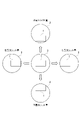
- FIG. 1 is a diagram showing a relationship between a display element in a projector and an effective image circle of a projection lens.
- FIG. 2 shows a state in which the effective image circle is displaced by the maximum shift amount in the horizontal direction and a state in which the effective image circle is displaced by the maximum shift amount in the vertical direction from the state where the display element is located at the center of the effective image circle of the projection lens. It is a figure which shows.
- FIG. 3 is a diagram showing a shift tolerance in all directions around the display element of the effective image circle. In FIG. 4, the effective image circle is displaced by the maximum shift amount in the horizontal direction without considering the shift amount in the vertical direction, and the effective image circle is displaced by the maximum shift amount in the vertical direction without considering the shift amount in the horizontal direction.
- FIG. 5 is a plan view showing a state in which various parts including a projection lens and a mask member are attached to the base.
- FIG. 6 is a plan view showing a state in which the projection lens and the mask member in FIG. 5 are removed and various parts including a horizontal stage and a vertical stage for displacing the projection lens are attached to the base.
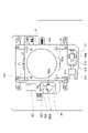
- FIG. 7 is a plan view showing a state in which the horizontal stage and the vertical stage in FIG. 6 are removed and a shift tolerance plate is attached to the base.
- FIG. 8 is a plan view showing a state in which the shift allowance plate in FIG. 7 is removed.
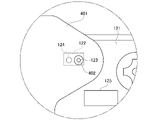
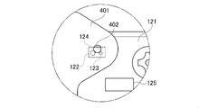
- FIG. 9 is a partially enlarged plan view showing the positional relationship between the light emitting portion and the through hole formed in the shift allowable plate in a state where the projection lens 20 is not displaced.
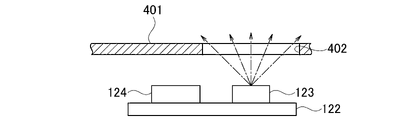
- FIG. 10A is a diagram showing that the light receiving unit does not receive the light emitted from the light emitting unit while the light emitting unit faces the through hole.
- FIG. 10B is a diagram showing that the light receiving unit receives the light emitted from the light emitting unit while the light emitting unit does not face the through hole.
- FIG. 11 is a partial plan view showing the positional relationship between the projection lens and the aperture when the projection lens 20 is not displaced.
- FIG. 10A is a diagram showing that the light receiving unit does not receive the light emitted from the light emitting unit while the light emitting unit faces the through hole.
- FIG. 10B is a diagram showing that the light receiving unit receives the light emitted from the light emitting unit while the light emitting unit does not face the through hole.
- FIG. 11 is a
- FIG. 12 is a partial plan view showing a state in which the projection lens 20 is displaced to the right and the outer peripheral surface of the projection lens is in contact with the shift tolerance plate at the right end of the aperture.
- FIG. 13 is a partial plan view showing a state in which the projection lens 20 displaced to the right pushes the shift allowance plate to the right and is displaced.
- FIG. 14 is a partially enlarged plan view showing the positional relationship between the light emitting portion and the through hole in the state of FIG.
- FIG. 15 is a partial plan view showing a state in which the projection lens 20 is displaced upward and the outer peripheral surface of the projection lens is in contact with the shift tolerance plate at the upper end of the aperture.
- FIG. 16 is a partial plan view showing a state in which the projection lens 20 displaced upward pushes the shift allowance plate upward and is displaced.
- FIG. 17 is a partially enlarged plan view showing the positional relationship between the light emitting portion and the through hole in the state of FIG.
- FIG. 18 is a partial plan view showing a state in which the projection lens 20 is displaced in the upper left direction and the projection lens 20 displaced in the upper left direction pushes the shift allowance plate in the upper left direction and is displaced.
- FIG. 19 is a partially enlarged plan view showing the positional relationship between the light emitting portion and the through hole in the state of FIG.
- the projector includes, for example, a display element 1 which is a liquid crystal display element.
- the display element 1 may be a reflective liquid crystal display element called LCOS (Liquid Crystal On Silicon).
- the projector includes a projection lens for projecting image light based on the image displayed on the display element 1 onto a screen or the like.
- FIG. 1 shows the relationship between the display element 1 and the effective image circle 2 of the projection lens. When the effective image circle 2 is displaced from the display element 1 by displacing the projection lens in the horizontal direction or the vertical direction, vignetting occurs in the projected image light.
- FIG. 2 shows a state in which the effective image circle 2 is displaced by the maximum shift amount in the horizontal direction (horizontal direction) from the state where the display element 1 is located in the center of the effective image circle 2 of the projection lens, and a state in which the effective image circle 2 is displaced in the vertical direction (vertical direction). It shows a state of being displaced by the maximum shift amount in the vertical direction).
- the projector displaces the projection lens only in the horizontal direction
- the projector can displace the projection lens in the left-right direction in the range from the maximum left shift amount to the maximum right shift amount.
- the projector can displace the projection lens in the vertical direction in the range from the maximum shift amount up to the maximum shift amount down.
- FIG. 3 shows a shift tolerance 3 in all directions around the display element 1 of the effective image circle 2. Displace the projection lens when the projection lens is displaced in either the horizontal direction or the vertical direction, or in any direction that combines the horizontal direction and the vertical direction without causing eclipse in the projected image light.
- the range that can be made is the shift allowable range 3 shown in FIG.
- the shift tolerance 3 has the shape shown in FIG.
- the projector has a sensor that detects that the projection lens has been displaced to the maximum left shift amount, a sensor that detects that the projection lens has been displaced to the maximum right shift amount, and a sensor that detects that the projection lens has been displaced to the maximum upper shift amount. It is assumed that a sensor for detecting displacement up to the lower maximum shift amount is provided. Then, as shown in FIG. 4, the projector can displace the projection lens in the horizontal direction by the maximum left-right shift amount without considering the vertical shift amount. Further, the projector can be displaced in the vertical direction by the maximum vertical shift amount without considering the horizontal shift amount.
- the effective image circle 2 may come off from the display element 1 as shown by hatching the left and right ends of the display element 1. Therefore, in the configuration in which the projector is provided with the above-mentioned four sensors on the top, bottom, left, and right, it is not possible to prevent the occurrence of vignetting in the image light.
- the projector of one or more embodiments does not employ a configuration in which the projection lens is displaced within a range that does not exceed the limit position of horizontal or vertical displacement based on the number of pulses of the pulse motor.
- the projector of one or more embodiments does not adopt a configuration using four sensors of up, down, left, and right.
- FIG. 5 shows a state in which the projection lens 20 is indirectly attached to the base 100, which is a part of the housing of the projector.
- the drawings including the base 100 shown in FIGS. 5 and 5 show a state in which each component is viewed from the front surface of the base 100, which is the inside of the housing (a state in which the inside is viewed from the outside of the housing).
- An annular mask member 21 that prevents unnecessary light from leaking to the outside from the outer peripheral portion of the projection lens 20 is mounted around the projection lens 20.
- FIG. 6 shows a state in which the projection lens 20 and the mask member 21 in FIG. 5 are removed.
- the projector has a horizontally movable stage 31 for horizontally displaced the projection lens 20 and a vertically movable movable stage 31 for vertically dislocating the projection lens 20.
- a vertical stage 32 is provided.
- the horizontal stage 31 has an oval opening 31a (first opening), and the vertical stage 32 has a circular opening 32a (second opening).
- the projection lens 20 is fitted in the opening 31a and the opening 32a.
- the lead nut 101 is fixed to the base 100 by a pair of claws 102a and 102b provided on the base 100.
- a horizontal shift motor 311 for driving the horizontal stage 31 is attached to the horizontal stage 31.
- the horizontal shift motor 311 is a pulse motor.
- the rotation of the horizontal shift motor 311 is transmitted to the lead screw 313 that meshes with the lead nut 101 via the gear 312.
- the lead screw 313 is mounted on the horizontal stage 31. Therefore, when the horizontal shift motor 311 rotates, the entire horizontal stage 31, horizontal shift motor 311, gear 312, and lead screw 313 move in the horizontal direction (horizontal direction).
- the horizontal stage 31 moves along the horizontal rail provided on the base 100.
- the horizontal stage 31 moves integrally with the vertical stage 32.
- the lead nut 301 is fixed to the horizontal stage 31 by a pair of claws 302a and 302b provided on the horizontal stage 31.
- a vertical shift motor 321 for driving the vertical stage 32 is attached to the vertical stage 32.
- the vertical shift motor 321 is a pulse motor.
- the rotation of the vertical shift motor 321 is transmitted to the lead screw 323 that meshes with the lead nut 301 via the gear 322.
- the lead screw 323 is mounted on the vertical stage 32. Therefore, when the vertical shift motor 321 rotates, the entire vertical stage 32, vertical shift motor 321, gear 322, and lead screw 323 move in the vertical direction (vertical direction).
- the vertical stage 32 moves along a vertical rail provided on the horizontal stage 31.
- FIG. 7 shows a state in which the horizontal stage 31, the horizontal shift motor 311 and the gear 312, the lead screw 313, the vertical stage 32, the vertical shift motor 321 and the gear 322, the lead screw 323, and the lead nut 301 are removed in FIG. ing.
- the projector includes a shift tolerance plate 40.
- the shift tolerance plate 40 has an opening 40a (third opening) similar to the shift tolerance range 3 shown in FIG.
- the opening 40a is set to be slightly smaller than the outer line 3oc indicated by the alternate long and short dash line of the shift tolerance 3.
- the size of the aperture 40a is larger than the cross-sectional area of the projection lens 20 at the position of the shift tolerance plate 40. Therefore, the projection lens 20 is arranged in the opening 40a in a state of being in non-contact with the shift tolerance plate 40.
- the end portion of the opening 40a may be located at a position about 1 mm inward from the outer line 3oc.
- the size of the opening 40a similar to the shift tolerance 3 may be as long as the shift tolerance 3 or less, and may be the same size or slightly smaller. How small the opening 40a is compared to the shift tolerance 3 is a design matter.
- the right end portion of the shift tolerance plate 40 and the columnar pin 111 provided on the base 100 are connected by a spring 411.
- the left end of the shift tolerance plate 40 and the spring position adjusting component 415 are connected by a spring 412.
- the spring position adjusting component 415 is fixed to the base 100 with a pair of screws 416a and 416b.
- the spring position adjusting component 415 can adjust the position fixed to the base 100 by loosening the screws 416a and 416b and sliding them in the left-right direction.
- the upper end of the shift tolerance plate 40 and the columnar pin 113 provided on the base 100 are connected by a spring 413.
- the lower end of the shift tolerance plate 40 and the spring position adjusting component 417 are connected by a spring 414.
- the spring position adjusting component 417 is fixed to the base 100 with a pair of screws 418a and 418b.
- the position of the spring position adjusting component 417 to be fixed to the base 100 can be adjusted by loosening the screws 418a and 418b and sliding them in the vertical direction.
- the shift allowable plate 40 is adjusted in the mounting position with respect to the base 100 by adjusting the positions of the spring position adjusting parts 415 and 417 with respect to the base 100.
- the shift tolerance plate 40 can be displaced by a predetermined amount in the vertical and horizontal directions by the springs 411 to 414.
- a protrusion 401 is formed in the upper right corner of the shift allowance plate 40.
- the position of the protrusion 401 is not limited.
- a through hole 402 is formed in the protrusion 401.
- a substrate 121 is attached to the base 100 so as to face the protrusion 401. The role of the through hole 402 will be described later.
- FIG. 8 shows a state in which the shift tolerance plate 40 and the springs 411 to 414 in FIG. 7 are removed.
- the base 100 is formed with an opening 100a having a shape like a square with rounded corners.
- the image light emitted from the projection lens 20 is projected onto a screen or the like through the opening 100a.
- a substrate 121 is attached to the base 100 in the vicinity of the end of the opening 100a.
- a photoreflector 122 and a detector 125 which are examples of photosensors, are mounted on the substrate 121.
- the photo reflector 122 has a light emitting unit 123 and a light receiving unit 124.
- the light emitting unit 123 is an LED
- the light receiving unit 124 is a phototransistor.
- FIG. 9 is a partially enlarged plan view of the vicinity of the protrusion 401 of FIG. 7 in a state where the projection lens 20 is not displaced in any direction. In this state, the light emitting unit 123 just faces the through hole 402. It is desirable that the center of the light emitting portion 123 and the center of the through hole 402 coincide with each other.
- the light receiving unit 124 does not receive the light emitted from the light emitting unit 123.
- the shift allowance plate 40 is displaced in either direction, the position of the through hole 402 shifts, so that the light emitting portion 123 does not face the through hole 402.
- FIG. 10B when a portion of the protruding portion 401 other than the through hole 402 faces the light emitting portion 123, the light emitted from the light emitting portion 123 is reflected by the protruding portion 401. Therefore, the light receiving unit 124 receives the light emitted from the light emitting unit 123.
- the detector 125 receives the light from the state where the light receiving unit 124 does not receive the light. Based on the change to the state, it is detected that the shift tolerance plate 40 is displaced to the limit position in either direction.
- the detector 125 may be mounted on a place other than the substrate 121.
- the detector 125 can be configured as a voltage detector.
- the detector 125 may be composed of a microprocessor.
- FIGS. 11 to 19 will be used to explain how the detector 125 detects that the projection lens 20 has been displaced to the limit position when the projection lens 20 is displaced.
- the controller (not shown) does not displace the projection lens 20 in any direction
- the center of the projection lens 20 coincides with the center of the aperture 40a, as shown in FIG.
- the entire circumference of the outer peripheral surface 20s of the projection lens 20 is separated from the shift tolerance plate 40 by a predetermined distance at the end of the opening 40a, and is not in contact with the shift tolerance plate 40.
- the controller rotates the horizontal shift motor 311 to move the horizontal stage 31 to the right in order to displace the projection lens 20 to the right.
- the outer peripheral surface 20s of the projection lens 20 comes into contact with the shift tolerance plate 40 at the right end of the opening 40a.
- the opening 40a is slightly smaller than the outer line 3oc of the shift tolerance 3
- the projection lens 20 is not displaced to the limit position in the right direction.
- the light emitting unit 123 faces the through hole 402.
- the controller When the controller further rotates the horizontal shift motor 311 to move the horizontal stage 31 further to the right, the projection lens 20 pushes the shift allowance plate 40 to the right to displace it, as shown in FIG. Then, as shown in the partially enlarged plan view of FIG. 14, the through hole 402 is displaced to the right side of the light emitting unit 123, and the light receiving unit 124 receives the light emitted from the light emitting unit 123.
- the detector 125 detects that the shift tolerance plate 40 is displaced to the limit position in either direction by supplying a current of a predetermined value or more from the light receiving unit 124.
- the controller rotates the vertical shift motor 321 to move the vertical stage 32 upward in order to displace the projection lens 20 upward.
- the outer peripheral surface 20s of the projection lens 20 comes into contact with the shift tolerance plate 40 at the upper end portion of the opening 40a.
- the projection lens 20 is not displaced to the upper limit position.
- the light emitting unit 123 faces the through hole 402.
- the controller When the controller further rotates the vertical shift motor 321 to move the vertical stage 32 further upward, the projection lens 20 pushes the shift allowable plate 40 upward to displace it, as shown in FIG. Then, as shown in the partially enlarged plan view of FIG. 17, the through hole 402 is displaced upward from the light emitting unit 123, and the light receiving unit 124 receives the light emitted from the light emitting unit 123.
- the detector 125 detects that the shift tolerance plate 40 is displaced to the limit position in either direction by supplying a current of a predetermined value or more from the light receiving unit 124.
- the controller moves the horizontal stage 31 and the vertical stage 32 in the upper left direction in order to displace the projection lens 20 in the upper left direction, and the projection lens 20 pushes the shift allowance plate 40 in the upper left direction to displace it. It shows the state.
- the through hole 402 is displaced to the upper left side of the light emitting unit 123, and the light receiving unit 124 receives the light emitted from the light emitting unit 123.
- the detector 125 detects that the shift tolerance plate 40 is displaced to the limit position in either direction by supplying a current of a predetermined value or more from the light receiving unit 124.
- the controller moves one or both of the horizontal stage 31 and the vertical stage 32 in order to displace the projection lens 20 in any direction.
- the detector 125 displaced the shift tolerance plate 40 to the limit position. Detect that.
- the controller stops the displacement of the projection lens 20. Therefore, the projection lens 20 does not displace beyond the limit position.
- one photosensor photoreflector 122
- a configuration that almost certainly prevents the projection lens 20 from being displaced beyond the limit position can be realized with a simple configuration at low cost.
- the photoreflector 122 is used as the photosensor, but a photointerruptor may be used.
- the light receiving unit 124 does not receive the light emitted from the light emitting unit 123 and passed through the through hole 402 in a state where the projection lens 20 is not displaced.
- the light receiving unit 124 receives the light emitted from the light emitting unit 123 and reflected by the shift tolerance plate 40.
- the light emitting portion and the light receiving portion are arranged so as to face each other with the protruding portion 401 interposed therebetween.
- the light receiving unit receives the light emitted from the light emitting unit and passing through the through hole 402 in a state where the projection lens 20 is not displaced.
- the projection lens 20 is displaced to the limit position, the light emitted from the light emitting unit is blocked by the shift tolerance plate 40, so that the light receiving unit does not receive the light emitted from the light emitting unit.
- the photo reflector 122 it is preferable to use the photo reflector 122 rather than the photo interrupter. If the photo reflector 122 is used, the light emitting unit 123 and the light receiving unit 124 may be arranged on one side of the protruding portion 401, so that the configuration is simplified.
Landscapes
- Physics & Mathematics (AREA)
- General Physics & Mathematics (AREA)
- Optics & Photonics (AREA)
- Projection Apparatus (AREA)
- Transforming Electric Information Into Light Information (AREA)
- Lens Barrels (AREA)
- Engineering & Computer Science (AREA)
- Multimedia (AREA)
- Signal Processing (AREA)
Abstract
投射レンズ(20)が投射する画像光にケラレが発生することなく、投射レンズ(20)を任意の方向に変位させることができる範囲をシフト許容範囲とする。シフト許容プレート(40)は、シフト許容範囲と相似形でシフト許容範囲以下の大きさを有する開口(40a)と、発光部(123)から射出された光を通過させる貫通孔(402)を有する。投射レンズ(20)がいずれかの方向に変位してシフト許容プレート(40)を変位させると、受光部(124)が光を受光し、検出器(125)が、投射レンズ(20)が限界位置まで変位したことを検出する。
Description
本開示は、レンズシフト機能を備えるプロジェクタに関する。
プロジェクタは、画像光を投射する位置を変位させるために、投射レンズを水平方向及び垂直方向に変位させるレンズシフト機能を備えることがある。レンズシフト機能を備えるプロジェクタは、投射レンズを水平方向または垂直方向の変位の限界位置を超えて変位させると、投射する画像光にケラレが発生する。そこで、プロジェクタは、水平方向及び垂直方向の変位の限界位置を超えない範囲で投射レンズを変位させることが必要である(特許文献1参照)。
プロジェクタは、投射レンズを変位させるための駆動源としてパルスモータを用い、パルスモータのパルス数に基づいて水平方向または垂直方向の変位の限界位置を超えない範囲で投射レンズを変位させる構成を備えることがある。しかしながら、この構成では、パルスモータが何らかの不具合で脱調すると、投射レンズの正確な位置を検出することができず、投射レンズが限界位置を超えて変位してしまうおそれがある。
1またはそれ以上の実施形態は、投射レンズが限界位置を超えて変位することをほぼ確実に防止することができ、ケラレのない画像光を投射することができるプロジェクタを提供することを目的とする。
1またはそれ以上の実施形態に係る一態様によれば、表示素子と、前記表示素子に表示された画像に基づく画像光を投射する投射レンズと、前記投射レンズが嵌められる第1の開口を有し、前記第1の開口に嵌められている前記投射レンズを水平方向に変位させるための水平方向に移動自在の水平方向ステージと、前記投射レンズが嵌められる第2の開口を有し、前記第2の開口に嵌められている前記投射レンズを垂直方向に変位させるための垂直方向に移動自在の垂直方向ステージと、発光部と受光部とを有するフォトセンサと、前記投射レンズが投射する画像光にケラレが発生することなく、前記投射レンズを水平方向と垂直方向とのいずれか一方の方向、または水平方向と垂直方向とを組み合わせた任意の方向に変位させることができる範囲を前記投射レンズのシフト許容範囲とし、前記シフト許容範囲と相似形であり、前記シフト許容範囲以下の大きさを有する第3の開口と、前記発光部から射出された光を通過させる貫通孔とを有するシフト許容プレートとを備えるプロジェクタが提供される。
上記のプロジェクタにおいて、前記投射レンズは、前記第3の開口内に配置されており、前記投射レンズを変位させていない状態で、前記投射レンズは、前記投射レンズの外周面の全周が前記第3の開口の端部において前記シフト許容プレートと非接触であり、かつ、前記発光部は前記貫通孔と対向しており、前記水平方向ステージと前記垂直方向ステージとの少なくとも一方を移動させて前記投射レンズをいずれかの方向に変位させて、前記投射レンズの外周面が前記第3の開口の端部において前記シフト許容プレートと接触して前記シフト許容プレートを変位させたとき、前記受光部が前記発光部から射出された光を受光しない状態から受光する状態への変化、または、前記受光部が前記発光部から射出された光を受光する状態から受光しない状態への変化に基づいて、前記投射レンズが限界位置まで変位したことを検出する検出器をさらに備える。
1またはそれ以上の実施形態のプロジェクタによれば、投射レンズが限界位置を超えて変位することをほぼ確実に防止することができ、ケラレのない画像光を投射することができる。
以下、1またはそれ以上の実施形態のプロジェクタについて、添付図面を参照して説明する。図1に示すように、プロジェクタは、例えば液晶表示素子である表示素子1を備える。表示素子1は、LCOS(Liquid Crystal On Silicon)と称される反射型液晶表示素子であってもよい。後述するように、プロジェクタは、表示素子1に表示された画像に基づく画像光をスクリーン等に投射するための投射レンズを備える。図1は、表示素子1と投射レンズの有効像円2との関係を示している。投射レンズを水平方向または垂直方向に変位させて有効像円2が表示素子1から外れると、投射する画像光にケラレが発生する。
図2は、表示素子1が投射レンズの有効像円2の中央に位置している状態から、有効像円2を、水平方向(左右方向)に最大シフト量だけ変位した状態と、垂直方向(上下方向)に最大シフト量だけ変位した状態とを示している。プロジェクタは、投射レンズを水平方向のみに変位させるときには、左最大シフト量から右最大シフト量までの範囲で投射レンズを左右方向に変位させることができる。プロジェクタは、投射レンズを垂直方向のみに変位させるときには、上最大シフト量から下最大シフト量までの範囲で投射レンズを上下方向に変位させることができる。
図3は、有効像円2の表示素子1の周囲の全方向のシフト許容範囲3を示している。投射する画像光にケラレが発生することなく、投射レンズを水平方向と垂直方向とのいずれか一方の方向、または水平方向と垂直方向とを組み合わせた任意の方向に変位させるときの投射レンズを変位させることができる範囲は、図3に示すシフト許容範囲3となる。シフト許容範囲3は図3に示す形状を有する。
仮に、プロジェクタが、投射レンズが左最大シフト量まで変位したことを検出するセンサと、右最大シフト量まで変位したことを検出するセンサと、上最大シフト量まで変位したことを検出するセンサと、下最大シフト量まで変位したことを検出するセンサを備えるとする。すると、図4に示すように、プロジェクタは、投射レンズを、垂直方向のシフト量を考慮することなく、左右最大シフト量だけ水平方向に変位させることができる。また、プロジェクタは、水平方向のシフト量を考慮することなく、上下最大シフト量だけ垂直方向に変位させることができる。
ところが、投射レンズを図4に示す範囲で変位させると、表示素子1の左右端部にハッチングを付して示すように、有効像円2が表示素子1から外れる場合が発生する。よって、プロジェクタが上記の上下左右の4つのセンサを備える構成では、画像光におけるケラレの発生を防止することができない。
図5~図19を参照しながら、1またはそれ以上の実施形態のプロジェクタが採用する、水平方向または垂直方向の変位の限界位置を超えない範囲で投射レンズを変位させる構成を説明する。1またはそれ以上の実施形態のプロジェクタは、パルスモータのパルス数に基づいて水平方向または垂直方向の変位の限界位置を超えない範囲で投射レンズを変位させる構成を採用しない。1またはそれ以上の実施形態のプロジェクタは、上下左右の4つのセンサを用いる構成を採用しない。
図5は、プロジェクタの筐体の一部であるベース100に投射レンズ20が間接的に取り付けられている状態を示している。図5以降のベース100を含む図面は、筐体の内部であるベース100の前面から各部品を見た状態(筐体外側から内部を見た状態)を示している。投射レンズ20の周囲には、投射レンズ20の外周部から不要光が外部へと漏れ出ることを防ぐ円環状のマスク部材21が装着されている。
図6は、図5における投射レンズ20及びマスク部材21を取り外した状態を示している。図6に示すように、プロジェクタは、投射レンズ20を水平方向に変位させるための水平方向に移動自在の水平方向ステージ31と、投射レンズ20を垂直方向に変位させるための垂直方向に移動自在の垂直方向ステージ32とを備える。
水平方向ステージ31は長円形の開口31a(第1の開口)を有し、垂直方向ステージ32は円形の開口32a(第2の開口)を有する。投射レンズ20は開口31aと開口32aとに嵌められている。
ベース100には、ベース100に設けられた一対の爪102a及び102bによって、リードナット101が固定されている。水平方向ステージ31には、水平方向ステージ31を駆動するための水平シフトモータ311が取り付けられている。水平シフトモータ311はパルスモータである。
水平シフトモータ311の回転は、ギア312を介して、リードナット101と噛み合うリードスクリュー313に伝達される。リードスクリュー313は、水平方向ステージ31に載せられている。よって、水平シフトモータ311が回転すると、水平方向ステージ31、水平シフトモータ311、ギア312、リードスクリュー313の全体は、水平方向(左右方向)に移動する。水平方向ステージ31は、ベース100に設けられた水平方向のレールに沿って移動する。
垂直方向ステージ32は水平方向ステージ31に取り付けられているため、水平方向ステージ31は垂直方向ステージ32と一体的に移動する。
水平方向ステージ31には、水平方向ステージ31に設けられた一対の爪302a及び302bによって、リードナット301が固定されている。垂直方向ステージ32には、垂直方向ステージ32を駆動するための垂直シフトモータ321が取り付けられている。垂直シフトモータ321はパルスモータである。
垂直シフトモータ321の回転は、ギア322を介して、リードナット301と噛み合うリードスクリュー323に伝達される。リードスクリュー323は、垂直方向ステージ32に載せられている。よって、垂直シフトモータ321が回転すると、垂直方向ステージ32、垂直シフトモータ321、ギア322、リードスクリュー323の全体は、垂直方向(上下方向)に移動する。垂直方向ステージ32は、水平方向ステージ31に設けられた垂直方向のレールに沿って移動する。
図7は、図6における水平方向ステージ31、水平シフトモータ311、ギア312、リードスクリュー313、垂直方向ステージ32、垂直シフトモータ321、ギア322、リードスクリュー323、リードナット301を取り外した状態を示している。図7に示すように、プロジェクタは、シフト許容プレート40を備える。
シフト許容プレート40は、図3に示すシフト許容範囲3と相似形の開口40a(第3の開口)を有する。開口40aは、シフト許容範囲3の一点鎖線で示す外形線3ocよりもわずかに小さく設定されている。開口40aの大きさは、シフト許容プレート40の位置における投射レンズ20の断面積より大きい。よって、投射レンズ20は、開口40a内にシフト許容プレート40とは非接触の状態で配置される。
投射レンズ20の直径が40mm~50mmである場合を例とし、開口40aの端部は外形線3ocから内側に1mm程度離れた位置とすればよい。シフト許容範囲3と相似形の開口40aの大きさはシフト許容範囲3以下の大きさであればよく、同じ大きさであるかわずかに小さいのがよい。開口40aをシフト許容範囲3と比較してどの程度小さくするかは設計的な事項である。
図7において、シフト許容プレート40の右端部と、ベース100に設けられている円柱状のピン111とは、スプリング411で連結されている。シフト許容プレート40の左端部と、スプリング位置調整部品415とは、スプリング412で連結されている。スプリング位置調整部品415は、一対のねじ416a及び416bでベース100に固定されている。スプリング位置調整部品415は、ねじ416a及び416bを緩めて左右方向にスライドさせることによって、ベース100に固定する位置を調整することができる。
シフト許容プレート40の上端部と、ベース100に設けられている円柱状のピン113とは、スプリング413で連結されている。シフト許容プレート40の下端部と、スプリング位置調整部品417とは、スプリング414で連結されている。スプリング位置調整部品417は、一対のねじ418a及び418bでベース100に固定されている。スプリング位置調整部品417は、ねじ418a及び418bを緩めて上下方向にスライドさせることによって、ベース100に固定する位置を調整することができる。
シフト許容プレート40は、スプリング位置調整部品415及び417のベース100に対する位置を調整することによって、ベース100に対する取り付け位置が調整されている。シフト許容プレート40は、スプリング411~414によって、上下及び左右方向に所定量だけ変位可能である。
シフト許容プレート40の右上角には突出部401が形成されている。突出部401の位置は限定されない。突出部401には貫通孔402が形成されている。ベース100には、突出部401と対向するように基板121が取り付けられている。貫通孔402の役割について後述する。
図8は、図7におけるシフト許容プレート40及びスプリング411~414を取り外した状態を示している。図8に示すように、ベース100には、正方形の角を丸めたような形状を有する開口100aが形成されている。投射レンズ20より射出される画像光は、開口100aを通ってスクリーン等に投射される。
ベース100には、開口100aの端部に近接して基板121が取り付けられている。基板121には、フォトセンサの一例であるフォトリフレクタ122と検出器125とが実装されている。フォトリフレクタ122は、発光部123と受光部124とを有する。一例として、発光部123はLEDであり、受光部124はフォトトランジスタである。
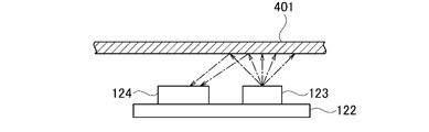
図9は、投射レンズ20をいずれの方向にも変位させていない状態における、図7の突出部401付近の部分拡大平面図である。この状態で、発光部123はちょうど貫通孔402と対向している。発光部123の中心と貫通孔402の中心とが一致していることが望ましい。
図10Aに示すように、発光部123が貫通孔402に臨んでいる状態では、発光部123から射出された光は貫通孔402を通過する。よって、受光部124は発光部123から射出された光を受光しない。シフト許容プレート40がいずれかの方向に変位すると、貫通孔402の位置がずれるから、発光部123は貫通孔402と対向しない状態となる。図10Bに示すように、突出部401の貫通孔402以外の部分が発光部123と対向すると、発光部123から射出された光は突出部401で反射する。よって、受光部124は発光部123から射出された光を受光する。
即ち、検出器125は、受光部124が発光部123から射出された光を受光して受光部124から所定値以上の電流が供給されると、受光部124が光を受光しない状態から受光する状態への変化に基づいて、シフト許容プレート40がいずれかの方向に限界位置まで変位したことを検出する。検出器125は、基板121以外のところに実装されていてもよい。検出器125は電圧検出器で構成することができる。検出器125は、マイクロプロセッサで構成されていてもよい。
図11~図19を用いて、投射レンズ20を変位させたときに、検出器125が、投射レンズ20が限界位置まで変位したことをどのように検出するかを説明する。図示していないコントローラが投射レンズ20をいずれの方向にも変位させていない状態においては、図11に示すように、投射レンズ20の中心は開口40aの中心と一致している。この状態で、投射レンズ20の外周面20sの全周は、開口40aの端部においてシフト許容プレート40と所定の距離だけ離れており、シフト許容プレート40と非接触である。
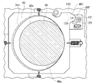
コントローラが投射レンズ20を右方向に変位させるために、水平シフトモータ311を回転させて水平方向ステージ31を右方向に移動させたとする。すると、図12に示すように、投射レンズ20の外周面20sは開口40aの右側端部においてシフト許容プレート40に接触する。この状態において、開口40aはシフト許容範囲3の外形線3ocよりもわずかに小さいため、投射レンズ20は右方向の限界位置まで変位していない。このとき、発光部123は貫通孔402と対向している。
コントローラが水平シフトモータ311をさらに回転させて水平方向ステージ31をさらに右方向に移動させると、図13に示すように、投射レンズ20はシフト許容プレート40を右方向に押して変位させる。すると、図14の部分拡大平面図に示すように、貫通孔402が発光部123よりも右側にずれて、受光部124が発光部123から射出された光を受光する。検出器125は、受光部124から所定値以上の電流が供給されることによって、シフト許容プレート40がいずれかの方向に限界位置まで変位したことを検出する。
コントローラが投射レンズ20を上方向に変位させるために、垂直シフトモータ321を回転させて垂直方向ステージ32を上方向に移動させたとする。すると、図15に示すように、投射レンズ20の外周面20sは開口40aの上側端部においてシフト許容プレート40に接触する。この状態において、投射レンズ20は上方向の限界位置まで変位していない。このとき、発光部123は貫通孔402と対向している。
コントローラが垂直シフトモータ321をさらに回転させて垂直方向ステージ32をさらに上方向に移動させると、図16に示すように、投射レンズ20はシフト許容プレート40を上方向に押して変位させる。すると、図17の部分拡大平面図に示すように、貫通孔402が発光部123よりも上側にずれて、受光部124が発光部123から射出された光を受光する。検出器125は、受光部124から所定値以上の電流が供給されることによって、シフト許容プレート40がいずれかの方向に限界位置まで変位したことを検出する。
図18は、コントローラが投射レンズ20を左上方向に変位させるために、水平方向ステージ31及び垂直方向ステージ32を左上方向に移動させ、投射レンズ20がシフト許容プレート40を左上方向に押して変位させた状態を示している。
この場合、図19の部分拡大平面図に示すように、貫通孔402が発光部123よりも左上側にずれて、受光部124が発光部123から射出された光を受光する。検出器125は、受光部124から所定値以上の電流が供給されることによって、シフト許容プレート40がいずれかの方向に限界位置まで変位したことを検出する。
このように、コントローラが投射レンズ20を任意の方向に変位させるために、水平方向ステージ31と垂直方向ステージ32とのうちの一方または双方を移動させる。投射レンズ20の外周面20sが開口40aのいずれかの位置の端部においてシフト許容プレート40に接触した後にシフト許容プレート40を変位させると、検出器125はシフト許容プレート40が限界位置まで変位したことを検出する。
検出器125が、シフト許容プレート40が限界位置まで変位したことを検出した時点で、コントローラは投射レンズ20の変位を停止させる。よって、投射レンズ20は限界位置を超えて変位しない。
このようにして、1またはそれ以上の実施形態のプロジェクタによれば、投射レンズ20が限界位置を超えて変位することをほぼ確実に防止することができる。よって、1またはそれ以上の実施形態のプロジェクタによれば、投射レンズ20をいずれの方向に変位させても、ケラレのない画像光を投射することができる。1またはそれ以上の実施形態のプロジェクタによれば、1つのフォトセンサ(フォトリフレクタ122)で周方向の全ての方向における投射レンズ20の変位の限界位置を検出することができる。投射レンズ20が限界位置を超えて変位することをほぼ確実に防止する構成を、低コストの簡単な構成で実現することができる。
1またはそれ以上の実施形態においては、フォトセンサとしてフォトリフレクタ122を用いているが、フォトインタラプタを用いてもよい。フォトリフレクタ122を用いる構成においては、投射レンズ20を変位させていない状態で、受光部124は、発光部123から射出されて貫通孔402を通過した光を受光しない。投射レンズ20が限界位置まで変位すると、受光部124は、発光部123から射出された光がシフト許容プレート40で反射した光を受光する。
フォトセンサとしてフォトインタラプタを用いる場合には、発光部と受光部とが突出部401を挟んで対向するように配置される。フォトインタラプタを用いる場合においては、投射レンズ20を変位させていない状態で、受光部は、発光部から射出されて貫通孔402を通過した光を受光する。投射レンズ20が限界位置まで変位すると、発光部から射出された光がシフト許容プレート40で遮られるので、受光部は、発光部から射出された光を受光しない。
フォトインタラプタよりもフォトリフレクタ122を用いる方が好ましい。フォトリフレクタ122を用いれば、発光部123と受光部124とを突出部401の一方側に配置すればよいため、構成が簡略化される。
本発明は以上説明した1またはそれ以上の実施形態に限定されるものではなく、本発明の要旨を逸脱しない範囲において種々変更である。
本願は、2020年12月16日に日本国特許庁に出願された特願2020-208292号に基づく優先権を主張するものであり、その全ての開示内容は引用によりここに援用される。
Claims (2)
- 表示素子と、
前記表示素子に表示された画像に基づく画像光を投射する投射レンズと、
前記投射レンズが嵌められる第1の開口を有し、前記第1の開口に嵌められている前記投射レンズを水平方向に変位させるための水平方向に移動自在の水平方向ステージと、
前記投射レンズが嵌められる第2の開口を有し、前記第2の開口に嵌められている前記投射レンズを垂直方向に変位させるための垂直方向に移動自在の垂直方向ステージと、
発光部と受光部とを有するフォトセンサと、
前記投射レンズが投射する画像光にケラレが発生することなく、前記投射レンズを水平方向と垂直方向とのいずれか一方の方向、または水平方向と垂直方向とを組み合わせた任意の方向に変位させることができる範囲を前記投射レンズのシフト許容範囲とし、前記シフト許容範囲と相似形であり、前記シフト許容範囲以下の大きさを有する第3の開口と、前記発光部から射出された光を通過させる貫通孔とを有するシフト許容プレートと、
を備え、
前記投射レンズは、前記第3の開口内に配置されており、
前記投射レンズを変位させていない状態で、前記投射レンズは、前記投射レンズの外周面の全周が前記第3の開口の端部において前記シフト許容プレートと非接触であり、かつ、前記発光部は前記貫通孔と対向しており、
前記水平方向ステージと前記垂直方向ステージとの少なくとも一方を移動させて前記投射レンズをいずれかの方向に変位させて、前記投射レンズの外周面が前記第3の開口の端部において前記シフト許容プレートと接触して前記シフト許容プレートを変位させたとき、前記受光部が前記発光部から射出された光を受光しない状態から受光する状態への変化、または、前記受光部が前記発光部から射出された光を受光する状態から受光しない状態への変化に基づいて、前記投射レンズが限界位置まで変位したことを検出する検出器をさらに備える
プロジェクタ。 - 前記フォトセンサは、
前記投射レンズを変位させていない状態で、前記受光部が、前記発光部から射出されて前記貫通孔を通過した光を受光せず、前記投射レンズが前記限界位置まで変位したときに、前記受光部が、前記発光部から射出された光が前記シフト許容プレートで反射した光を受光するフォトリフレクタと、
前記投射レンズを変位させていない状態で、前記受光部が、前記発光部から射出されて前記貫通孔を通過した光を受光し、前記投射レンズが前記限界位置まで変位したときに、前記発光部から射出された光が前記シフト許容プレートで遮られて前記発光部から射出された光を受光しないフォトインタラプタと、
のいずれかである請求項1に記載のプロジェクタ。
Priority Applications (1)
| Application Number | Priority Date | Filing Date | Title |
|---|---|---|---|
| US18/207,323 US12436453B2 (en) | 2020-12-16 | 2023-06-08 | Projector |
Applications Claiming Priority (2)
| Application Number | Priority Date | Filing Date | Title |
|---|---|---|---|
| JP2020-208292 | 2020-12-16 | ||
| JP2020208292A JP7517132B2 (ja) | 2020-12-16 | 2020-12-16 | プロジェクタ |
Related Child Applications (1)
| Application Number | Title | Priority Date | Filing Date |
|---|---|---|---|
| US18/207,323 Continuation US12436453B2 (en) | 2020-12-16 | 2023-06-08 | Projector |
Publications (1)
| Publication Number | Publication Date |
|---|---|
| WO2022130792A1 true WO2022130792A1 (ja) | 2022-06-23 |
Family
ID=82059754
Family Applications (1)
| Application Number | Title | Priority Date | Filing Date |
|---|---|---|---|
| PCT/JP2021/039481 Ceased WO2022130792A1 (ja) | 2020-12-16 | 2021-10-26 | プロジェクタ |
Country Status (3)
| Country | Link |
|---|---|
| US (1) | US12436453B2 (ja) |
| JP (1) | JP7517132B2 (ja) |
| WO (1) | WO2022130792A1 (ja) |
Citations (6)
| Publication number | Priority date | Publication date | Assignee | Title |
|---|---|---|---|---|
| JP2001215610A (ja) * | 2000-01-28 | 2001-08-10 | Nec Corp | レンズシフト機能付プロジェクタ装置 |
| JP2008058671A (ja) * | 2006-08-31 | 2008-03-13 | Sanyo Electric Co Ltd | 投写レンズ移動装置及びそれを用いた投写型映像表示装置 |
| JP2009211107A (ja) * | 2009-06-24 | 2009-09-17 | Sanyo Electric Co Ltd | レンズシフト機構及び投写型映像表示装置 |
| JP2010060806A (ja) * | 2008-09-03 | 2010-03-18 | Sony Corp | 投射型表示装置およびその駆動制御方法 |
| WO2011099111A1 (ja) * | 2010-02-09 | 2011-08-18 | Necディスプレイソリューションズ株式会社 | レンズ駆動装置、投射型表示装置、及びレンズ駆動方法 |
| JP2020076854A (ja) * | 2018-11-07 | 2020-05-21 | キヤノン株式会社 | 画像投射装置およびその制御方法 |
Family Cites Families (47)
| Publication number | Priority date | Publication date | Assignee | Title |
|---|---|---|---|---|
| JPH10171044A (ja) * | 1996-12-06 | 1998-06-26 | Matsushita Electric Ind Co Ltd | 液晶プロジェクション装置 |
| JP3266854B2 (ja) * | 1998-05-20 | 2002-03-18 | 旭光学工業株式会社 | 反射型画像投影装置 |
| AU769428B2 (en) * | 1999-01-29 | 2004-01-29 | Matsushita Electric Industrial Co., Ltd. | Liquid crystal projector |
| JP3606094B2 (ja) * | 1999-02-25 | 2005-01-05 | セイコーエプソン株式会社 | 投写型表示装置 |
| WO2001048551A1 (en) * | 1999-12-24 | 2001-07-05 | Matsushita Electric Industrial Co., Ltd. | Projector |
| US7164546B2 (en) * | 2002-04-24 | 2007-01-16 | Sanyo Electric Co., Ltd. | Lens shift mechanism and projection type video display |
| US6755540B1 (en) * | 2002-12-11 | 2004-06-29 | Virgil Sam Runco | Lens shifting apparatus |
| US7090360B2 (en) * | 2003-07-28 | 2006-08-15 | Seiko Epson Corporation | Projector |
| JP4171373B2 (ja) * | 2003-08-04 | 2008-10-22 | 三洋電機株式会社 | 投写型映像表示装置 |
| JP3963879B2 (ja) * | 2003-08-04 | 2007-08-22 | 三洋電機株式会社 | レンズシフト機構及び投写型映像表示装置 |
| US6909560B2 (en) * | 2003-10-15 | 2005-06-21 | Sheng-Feng Lin | Projection lens shifting mechanism |
| JP3960384B2 (ja) | 2003-12-15 | 2007-08-15 | Necディスプレイソリューションズ株式会社 | レンズシフト機能付プロジェクタ |
| JP4479630B2 (ja) * | 2005-09-06 | 2010-06-09 | セイコーエプソン株式会社 | プロジェクタ |
| JP5238130B2 (ja) * | 2005-12-12 | 2013-07-17 | 株式会社Suwaオプトロニクス | 投射型表示装置 |
| JP4902184B2 (ja) * | 2005-12-12 | 2012-03-21 | 株式会社Suwaオプトロニクス | 微小ミラー型表示素子を備える投射型表示装置 |
| JP4203829B2 (ja) * | 2006-09-29 | 2009-01-07 | ソニー株式会社 | レンズシフト機構 |
| TWI334057B (en) * | 2007-06-29 | 2010-12-01 | Coretronic Corp | Lens shifting device |
| TWI361285B (en) * | 2007-08-07 | 2012-04-01 | Coretronic Corp | Adjustment module for lens |
| JP4433054B2 (ja) * | 2008-01-23 | 2010-03-17 | セイコーエプソン株式会社 | プロジェクタ |
| JP4479798B2 (ja) * | 2008-01-23 | 2010-06-09 | セイコーエプソン株式会社 | プロジェクタ |
| TW201009484A (en) * | 2008-08-20 | 2010-03-01 | Coretronic Corp | Lens-adjusting module |
| TWI409573B (zh) * | 2009-02-12 | 2013-09-21 | Delta Electronics Inc | 二維調整結構及包含該二維調整結構之投影裝置 |
| JP5426257B2 (ja) * | 2009-07-03 | 2014-02-26 | 富士フイルム株式会社 | レンズ鏡筒のシフト機構及びプロジェクタ |
| JP2011085799A (ja) * | 2009-10-16 | 2011-04-28 | Sanyo Electric Co Ltd | レンズシフト装置及びこれを用いた投写型映像表示装置 |
| JP2011085798A (ja) * | 2009-10-16 | 2011-04-28 | Sanyo Electric Co Ltd | レンズシフト機構および投写型映像表示装置 |
| WO2011108074A1 (ja) * | 2010-03-02 | 2011-09-09 | Necディスプレイソリューションズ株式会社 | レンズシフト装置及びレンズシフト装置を備えた投写型表示装置 |
| JP5691257B2 (ja) * | 2010-06-22 | 2015-04-01 | セイコーエプソン株式会社 | プロジェクター |
| JP5786117B2 (ja) * | 2010-10-22 | 2015-09-30 | パナソニックIpマネジメント株式会社 | レンズシフト機構および投写型映像表示装置 |
| JP5637895B2 (ja) * | 2011-02-24 | 2014-12-10 | キヤノン株式会社 | 画像投射装置 |
| JP2012189761A (ja) * | 2011-03-10 | 2012-10-04 | Seiko Epson Corp | プロジェクターおよび画像表示システム |
| WO2012124105A1 (ja) * | 2011-03-17 | 2012-09-20 | Necディスプレイソリューションズ株式会社 | レンズ着脱装置及び投写型表示装置 |
| TWI444688B (zh) * | 2011-05-11 | 2014-07-11 | Delta Electronics Inc | 傳動總成 |
| CN102854722B (zh) * | 2011-07-01 | 2015-04-22 | 中强光电股份有限公司 | 投影装置及其光源调整方法 |
| CN103890655B (zh) * | 2011-10-13 | 2016-03-23 | 日立麦克赛尔株式会社 | 投影型影像显示装置 |
| JP6191111B2 (ja) * | 2012-09-28 | 2017-09-06 | セイコーエプソン株式会社 | プロジェクター |
| US9154755B2 (en) * | 2012-09-28 | 2015-10-06 | Seiko Epson Corporation | Projector with a lens shift mechanism configured to move a projection lens |
| JP2015184353A (ja) * | 2014-03-20 | 2015-10-22 | セイコーエプソン株式会社 | プロジェクター |
| WO2016185550A1 (ja) * | 2015-05-19 | 2016-11-24 | 日立マクセル株式会社 | 投射型映像表示装置 |
| CN106324960B (zh) * | 2015-07-07 | 2018-10-30 | 中强光电股份有限公司 | 投影装置及镜头模组 |
| CN111258154B (zh) * | 2015-10-15 | 2021-06-11 | 麦克赛尔株式会社 | 投射型影像显示装置 |
| US10082729B2 (en) * | 2016-09-29 | 2018-09-25 | Seiko Epson Corporation | Projector |
| CN108072954B (zh) * | 2016-11-15 | 2023-11-24 | 深圳光峰科技股份有限公司 | 镜头密封套、镜头模组、镜头调整模组及投影设备 |
| CN109725479B (zh) * | 2017-10-31 | 2021-08-10 | 中强光电股份有限公司 | 投影机与镜头模块 |
| EP3845965B1 (en) * | 2018-08-31 | 2024-07-10 | Sony Group Corporation | Lens shift mechanism and projection display device |
| JP6988770B2 (ja) * | 2018-11-12 | 2022-01-05 | セイコーエプソン株式会社 | 投射型表示装置およびレンズ保持機構 |
| KR102668749B1 (ko) * | 2019-01-16 | 2024-05-23 | 엘지전자 주식회사 | 프로젝터 |
| CN112578611B (zh) * | 2019-09-30 | 2024-10-29 | 深圳光峰科技股份有限公司 | 镜头调节装置及投影设备 |
-
2020
- 2020-12-16 JP JP2020208292A patent/JP7517132B2/ja active Active
-
2021
- 2021-10-26 WO PCT/JP2021/039481 patent/WO2022130792A1/ja not_active Ceased
-
2023
- 2023-06-08 US US18/207,323 patent/US12436453B2/en active Active
Patent Citations (6)
| Publication number | Priority date | Publication date | Assignee | Title |
|---|---|---|---|---|
| JP2001215610A (ja) * | 2000-01-28 | 2001-08-10 | Nec Corp | レンズシフト機能付プロジェクタ装置 |
| JP2008058671A (ja) * | 2006-08-31 | 2008-03-13 | Sanyo Electric Co Ltd | 投写レンズ移動装置及びそれを用いた投写型映像表示装置 |
| JP2010060806A (ja) * | 2008-09-03 | 2010-03-18 | Sony Corp | 投射型表示装置およびその駆動制御方法 |
| JP2009211107A (ja) * | 2009-06-24 | 2009-09-17 | Sanyo Electric Co Ltd | レンズシフト機構及び投写型映像表示装置 |
| WO2011099111A1 (ja) * | 2010-02-09 | 2011-08-18 | Necディスプレイソリューションズ株式会社 | レンズ駆動装置、投射型表示装置、及びレンズ駆動方法 |
| JP2020076854A (ja) * | 2018-11-07 | 2020-05-21 | キヤノン株式会社 | 画像投射装置およびその制御方法 |
Also Published As
| Publication number | Publication date |
|---|---|
| JP7517132B2 (ja) | 2024-07-17 |
| US12436453B2 (en) | 2025-10-07 |
| JP2022095141A (ja) | 2022-06-28 |
| US20230324775A1 (en) | 2023-10-12 |
Similar Documents
| Publication | Publication Date | Title |
|---|---|---|
| JP6847189B2 (ja) | プロジェクタ | |
| JP5060792B2 (ja) | 投写光学系、投写用ユニットおよび投写型表示装置 | |
| CN112955819A (zh) | 投影透镜及投影装置 | |
| JP2872626B2 (ja) | プロジェクタ用傾斜角感知装置 | |
| US11539930B2 (en) | Projection apparatus | |
| US10642137B2 (en) | Projection-type image display device | |
| TWI311681B (en) | Reflective mirror module and projection apparatus using the same | |
| US12436453B2 (en) | Projector | |
| CN107121873B (zh) | 光学装置 | |
| JP2015075510A (ja) | 投影装置及び虚像表示装置 | |
| JP2014203012A (ja) | ヘッドアップディスプレイ装置 | |
| JP2005148381A (ja) | プロジェクタおよび移動検出方法、映像調整方法 | |
| JP4278422B2 (ja) | 鏡筒支持装置および投射型表示装置 | |
| US10591811B2 (en) | Projector and control method | |
| JPH0829657A (ja) | レンズ鏡筒 | |
| US11199694B2 (en) | Projection apparatus | |
| US20240310701A1 (en) | Projection lens module and projection device | |
| JP2005164942A (ja) | 光源光調節用の絞り装置 | |
| JP2023179213A (ja) | レンズ鏡筒及び光学機器 | |
| US20080304021A1 (en) | Light-shielding module and projection apparatus using the same | |
| JP2005121977A (ja) | 光照射装置、投射型表示装置および光照射方法 | |
| CN113448147A (zh) | 投影仪 | |
| US20090103057A1 (en) | Automatic iris diaphragm module |
Legal Events
| Date | Code | Title | Description |
|---|---|---|---|
| 121 | Ep: the epo has been informed by wipo that ep was designated in this application |
Ref document number: 21906156 Country of ref document: EP Kind code of ref document: A1 |
|
| NENP | Non-entry into the national phase |
Ref country code: DE |
|
| 122 | Ep: pct application non-entry in european phase |
Ref document number: 21906156 Country of ref document: EP Kind code of ref document: A1 |