WO2022025268A1 - 硫化物系固体電解質の製造方法及び硫化物系固体電解質 - Google Patents
硫化物系固体電解質の製造方法及び硫化物系固体電解質 Download PDFInfo
- Publication number
- WO2022025268A1 WO2022025268A1 PCT/JP2021/028382 JP2021028382W WO2022025268A1 WO 2022025268 A1 WO2022025268 A1 WO 2022025268A1 JP 2021028382 W JP2021028382 W JP 2021028382W WO 2022025268 A1 WO2022025268 A1 WO 2022025268A1
- Authority
- WO
- WIPO (PCT)
- Prior art keywords
- sulfide
- solid electrolyte
- based solid
- sulfur
- lithium
- Prior art date
Links
Images
Classifications
-
- C—CHEMISTRY; METALLURGY
- C01—INORGANIC CHEMISTRY
- C01B—NON-METALLIC ELEMENTS; COMPOUNDS THEREOF; METALLOIDS OR COMPOUNDS THEREOF NOT COVERED BY SUBCLASS C01C
- C01B25/00—Phosphorus; Compounds thereof
- C01B25/14—Sulfur, selenium, or tellurium compounds of phosphorus
-
- H—ELECTRICITY
- H01—ELECTRIC ELEMENTS
- H01M—PROCESSES OR MEANS, e.g. BATTERIES, FOR THE DIRECT CONVERSION OF CHEMICAL ENERGY INTO ELECTRICAL ENERGY
- H01M10/00—Secondary cells; Manufacture thereof
- H01M10/05—Accumulators with non-aqueous electrolyte
- H01M10/056—Accumulators with non-aqueous electrolyte characterised by the materials used as electrolytes, e.g. mixed inorganic/organic electrolytes
- H01M10/0561—Accumulators with non-aqueous electrolyte characterised by the materials used as electrolytes, e.g. mixed inorganic/organic electrolytes the electrolyte being constituted of inorganic materials only
- H01M10/0562—Solid materials
-
- H—ELECTRICITY
- H01—ELECTRIC ELEMENTS
- H01B—CABLES; CONDUCTORS; INSULATORS; SELECTION OF MATERIALS FOR THEIR CONDUCTIVE, INSULATING OR DIELECTRIC PROPERTIES
- H01B1/00—Conductors or conductive bodies characterised by the conductive materials; Selection of materials as conductors
- H01B1/06—Conductors or conductive bodies characterised by the conductive materials; Selection of materials as conductors mainly consisting of other non-metallic substances
- H01B1/10—Conductors or conductive bodies characterised by the conductive materials; Selection of materials as conductors mainly consisting of other non-metallic substances sulfides
-
- H—ELECTRICITY
- H01—ELECTRIC ELEMENTS
- H01B—CABLES; CONDUCTORS; INSULATORS; SELECTION OF MATERIALS FOR THEIR CONDUCTIVE, INSULATING OR DIELECTRIC PROPERTIES
- H01B13/00—Apparatus or processes specially adapted for manufacturing conductors or cables
-
- H—ELECTRICITY
- H01—ELECTRIC ELEMENTS
- H01M—PROCESSES OR MEANS, e.g. BATTERIES, FOR THE DIRECT CONVERSION OF CHEMICAL ENERGY INTO ELECTRICAL ENERGY
- H01M10/00—Secondary cells; Manufacture thereof
- H01M10/05—Accumulators with non-aqueous electrolyte
- H01M10/052—Li-accumulators
-
- H—ELECTRICITY
- H01—ELECTRIC ELEMENTS
- H01M—PROCESSES OR MEANS, e.g. BATTERIES, FOR THE DIRECT CONVERSION OF CHEMICAL ENERGY INTO ELECTRICAL ENERGY
- H01M10/00—Secondary cells; Manufacture thereof
- H01M10/05—Accumulators with non-aqueous electrolyte
- H01M10/052—Li-accumulators
- H01M10/0525—Rocking-chair batteries, i.e. batteries with lithium insertion or intercalation in both electrodes; Lithium-ion batteries
-
- C—CHEMISTRY; METALLURGY
- C01—INORGANIC CHEMISTRY
- C01P—INDEXING SCHEME RELATING TO STRUCTURAL AND PHYSICAL ASPECTS OF SOLID INORGANIC COMPOUNDS
- C01P2002/00—Crystal-structural characteristics
- C01P2002/04—Compounds with a limited amount of crystallinty, e.g. as indicated by a crystallinity index
-
- C—CHEMISTRY; METALLURGY
- C01—INORGANIC CHEMISTRY
- C01P—INDEXING SCHEME RELATING TO STRUCTURAL AND PHYSICAL ASPECTS OF SOLID INORGANIC COMPOUNDS
- C01P2002/00—Crystal-structural characteristics
- C01P2002/80—Crystal-structural characteristics defined by measured data other than those specified in group C01P2002/70
- C01P2002/82—Crystal-structural characteristics defined by measured data other than those specified in group C01P2002/70 by IR- or Raman-data
-
- H—ELECTRICITY
- H01—ELECTRIC ELEMENTS
- H01M—PROCESSES OR MEANS, e.g. BATTERIES, FOR THE DIRECT CONVERSION OF CHEMICAL ENERGY INTO ELECTRICAL ENERGY
- H01M2300/00—Electrolytes
- H01M2300/0017—Non-aqueous electrolytes
- H01M2300/0065—Solid electrolytes
- H01M2300/0068—Solid electrolytes inorganic
-
- Y—GENERAL TAGGING OF NEW TECHNOLOGICAL DEVELOPMENTS; GENERAL TAGGING OF CROSS-SECTIONAL TECHNOLOGIES SPANNING OVER SEVERAL SECTIONS OF THE IPC; TECHNICAL SUBJECTS COVERED BY FORMER USPC CROSS-REFERENCE ART COLLECTIONS [XRACs] AND DIGESTS
- Y02—TECHNOLOGIES OR APPLICATIONS FOR MITIGATION OR ADAPTATION AGAINST CLIMATE CHANGE
- Y02E—REDUCTION OF GREENHOUSE GAS [GHG] EMISSIONS, RELATED TO ENERGY GENERATION, TRANSMISSION OR DISTRIBUTION
- Y02E60/00—Enabling technologies; Technologies with a potential or indirect contribution to GHG emissions mitigation
- Y02E60/10—Energy storage using batteries
Definitions
- the present invention relates to a method for producing a sulfide-based solid electrolyte and a sulfide-based solid electrolyte.
- Lithium-ion secondary batteries are widely used in portable electronic devices such as mobile phones and notebook personal computers.
- a liquid electrolyte has been used in a lithium ion secondary battery, but there is a concern about liquid leakage and ignition, and it is necessary to increase the size of the case for safety design. Further, it has been desired to improve the short battery life and the narrow operating temperature range.
- an all-solid-state lithium-ion secondary battery that uses a solid electrolyte as an electrolyte for a lithium-ion secondary battery is attracting attention because it can be expected to improve safety, charge / discharge at high speed, and reduce the size of the case.
- Solid electrolytes are roughly classified into sulfide-based solid electrolytes and oxide-based solid electrolytes.
- the sulfide ions constituting the sulfide-based solid electrolyte have a larger polarizability than the oxide ions constituting the oxide-based solid electrolyte and exhibit high ionic conductivity.
- Examples of the sulfide-based solid electrolyte include a sulfide-based solid electrolyte containing a lithium element, a sulfur element, and a phosphorus element, and examples thereof include a glass sealing method, a mechanical milling method, and a melting method. There is. However, the glass sealing method and the mechanical milling method are not suitable for mass production because they are batch processes and the reaction takes a long time.
- the melting method is a manufacturing method capable of mass production
- the boiling point of diphosphorus pentasulfide (P 2 S 5 ) is 514 ° C
- the melting point of lithium sulfide (Li 2 S) is 514 ° C. Since it is 938 ° C., when Li 2 S is heated and melted, P 2 S 5 volatilizes at a temperature significantly lower than that temperature. Therefore, there is a problem that it is difficult to control the composition of the obtained sulfide-based solid electrolyte.
- Patent Document 1 discloses that a composite compound containing lithium, phosphorus and sulfur as a composition is used as a raw material in the production of a lithium ion conductive material. It is disclosed that this does not cause the problem that only the P2 S5 component volatilizes at the time of melting, that is, the sulfur component and the phosphorus component volatilize, so that a homogeneous lithium ion conductive material having a desired composition can be stably produced. Has been done.
- the complex compound itself described in Patent Document 1 is considered to be an intermediate obtained by heating a mixture of Li 2S and P 2 S 5 , and the sulfur component and the phosphorus component are still volatilized in the step of obtaining the complex compound. It's easy to do. In the conventional technique, there is still room for improvement in terms of composition controllability from the starting material to the target sulfide-based solid electrolyte.
- the composition controllability is insufficient, a deviation between the target composition of the sulfide-based solid electrolyte and the actually obtained composition tends to occur.
- the obtained sulfide-based solid electrolyte tends to be inhomogeneous.
- the inhomogeneous sulfide-based solid electrolyte may be inferior in terms of lithium ion conductivity. That is, in the conventional technique, there is room for improvement in the homogeneity and lithium ion conductivity of the obtained sulfide-based solid electrolyte as well as the composition controllability.
- an object of the present invention is to provide a method for producing a sulfide-based solid electrolyte, which suppresses the volatilization of sulfur and phosphorus components, has a small composition deviation from the raw material, has excellent composition controllability, and is easy to mass-produce. do.
- Another object of the present invention is to provide a sulfide-based solid electrolyte having excellent homogeneity and excellent lithium ion conductivity.
- the present inventors obtained an intermediate by heat-treating a raw material containing a lithium element, a sulfur element and a phosphorus element, and further heated the intermediate in a gas atmosphere containing a sulfur element.
- the present invention relates to the following [1] to [13].
- [1] To obtain an intermediate by heat-treating a raw material containing an element of lithium, an element of sulfur and an element of phosphorus, Including heating and melting the intermediate in a gas atmosphere containing sulfur elements.
- a method for producing a sulfide-based solid electrolyte [2] The method for producing a sulfide-based solid electrolyte according to 1 above, wherein the temperature at which the raw material is heated in the heat treatment is in the range of 250 to 500 ° C. [3] Further comprising recovering a component containing a sulfur element volatilized from the raw material when obtaining the intermediate.
- a gas derived from the sulfur element-containing component is used as at least a part of the sulfur-containing gas.
- the raw material contains one or more selected from the group consisting of metallic lithium, lithium sulfide, lithium carbonate, lithium sulfate, lithium oxide and lithium hydroxide.
- a method for producing a sulfide-based solid electrolyte which further comprises cooling the melt obtained by heating and melting to obtain a solid, wherein the melt contains 0.01% by mass of a compound as a crystal nucleus.
- the method for producing a sulfide-based solid electrolyte according to any one of 1 to 8 further comprising quenching the melt obtained by heating and melting to obtain a solid.
- the volatilization of sulfur components and phosphorus components in the raw material can be suppressed by passing through an intermediate until the desired sulfide-based solid electrolyte is obtained from the raw material. Further, by passing through the intermediate, it becomes easier to control the composition as compared with the case where the desired sulfide-based solid electrolyte is directly obtained from the raw material. Then, when an intermediate is obtained, although a certain amount of sulfur component is still volatilized, the intermediate is heated and melted in a gas atmosphere containing a sulfur element in order to obtain a sulfide-based solid electrolyte having a target composition. A sufficient amount of sulfur component can be introduced.
- the intermediate in the production method of the present invention is in a thermodynamically stable state, and therefore, after synthesizing the intermediate, the reaction temperature can be lowered to room temperature and taken out.
- the intermediate taken out in this way can be temporarily stored, or the intermediate taken out in the melting step, which is the next step, can be used.
- the intermediate in the production method of the present invention is synthesized by controlling the reaction, the composition information can be clarified by detailed composition analysis.
- the method for producing a sulfide-based solid electrolyte of the present invention it is easy to control the amount of sulfur introduced into an intermediate in a molten state in a molten state in a gas atmosphere containing a sulfur element (S), and sulfur deficiency occurs. Is less and less likely to cause composition deviation.
- S sulfur element
- the difference between the composition of the target sulfide-based solid electrolyte and the composition of the sulfide-based solid electrolyte obtained from the raw material is small, and the composition can be controlled. It is possible to provide an easy method for producing a sulfide-based solid electrolyte. According to this production method, the controllability of the physical properties of the obtained sulfide-based solid electrolyte can be improved due to the excellent composition controllability, and as a result, the lithium ion conductivity suitable as the electrolyte of the lithium ion secondary battery is high. It facilitates the stable and highly reproducible production of sulfide-based solid electrolytes. Furthermore, since the present production method is excellent in composition controllability, the obtained sulfide-based solid electrolyte is also excellent in homogeneity and lithium ion conductivity.
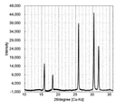
- FIG. 1 is a diagram showing XRD measurement results of the sulfide-based solid electrolyte of Example 1.
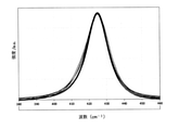
- FIG. 2 is a diagram showing Raman spectrum measurement results of the sulfide-based solid electrolyte of Example 1.
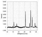
- FIG. 3 is a diagram showing the XRD measurement results of the sulfide-based solid electrolyte of Example 2.
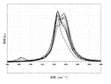
- FIG. 4 is a diagram showing Raman spectrum measurement results of the sulfide-based solid electrolyte of Example 2.
- a raw material containing a lithium element, a sulfur element and a phosphorus element is heat-treated to obtain an intermediate. It includes a step (intermediate synthesis step) and a step of heating and melting the intermediate in a gas atmosphere containing a sulfur element (heat melting step). Further, in this manufacturing method, a step of further cooling the melt obtained by heating and melting (cooling step), a step of reheating the solid obtained by the cooling step (reheating step), a crushing step, and a drying step. Etc., other steps may be included as appropriate. Hereinafter, each step will be described.
- the present production method includes an intermediate synthesis step of heat-treating a raw material containing a lithium element, a sulfur element and a phosphorus element to obtain an intermediate.
- the raw material of this production method contains a lithium element (Li), a sulfur element (S) and a phosphorus element (P).
- Such raw materials include Li-containing substances (components) such as Li alone and compounds containing Li, S-containing substances (components) such as S-only substances and compounds containing S, and P such as P alone and compounds containing P. Substances (ingredients) and the like can be used in combination as appropriate.
- the compound containing Li, the compound containing S, and the compound containing P may be a compound containing two or more selected from Li, S, and P.
- examples of the compound containing S and the compound containing P include diphosphorus pentasulfide (P 2 S 5 ).
- Examples of the substance containing Li include lithium sulfide (Li 2 S), lithium carbonate (Li 2 CO 3 ), lithium sulfate (Li 2 SO 4 ), lithium oxide (Li 2 O) and lithium hydroxide (LiOH).
- Examples thereof include lithium compounds of the above and metallic lithium.
- Lithium sulfide is preferably used from the viewpoint of ease of intermediate synthesis and ease of handling.
- lithium sulfide is expensive, it is preferable to use a lithium compound other than lithium sulfide, metallic lithium, or the like from the viewpoint of suppressing the production cost of the sulfide-based solid electrolyte.
- the raw materials are lithium metal, lithium carbonate (Li 2 CO 3 ), lithium sulfate (Li 2 SO 4 ), lithium oxide (Li 2 O) and lithium hydroxide (LiOH) as substances containing Li. It is preferable to include 1 or more selected from the group consisting of. These substances may be used alone or in combination of two or more.
- Examples of the substance containing S include phosphorus sulfide such as diphosphorus trisulfide (P 2 S 3 ) and diphosphorus pentasulfide (P 2 S 5 ), other sulfur compounds containing phosphorus, and simple sulfur and sulfur. Examples include compounds. Examples of sulfur-containing compounds include H 2 S, CS 2 , iron sulfide (FeS, Fe 2 S 3 , FeS 2 , Fe 1-x S, etc.), bismuth sulfide (Bi 2 S 3 ), and copper sulfide (CuS, Cu). 2S, Cu 1 - x S, etc.).
- the substance containing S is preferably phosphorus pentasulfide (P) from the viewpoint of ease of reaction in the intermediate synthesis step and prevention of the inclusion of elements other than the elements constituting the target sulfide-based solid electrolyte. 2 S 5 ) is more preferable. These substances may be used alone or in combination of two or more. In addition, phosphorus sulfide is considered as a compound having both a substance containing S and a substance containing P.
- substances containing P include phosphorus sulfide such as diphosphorus trisulfide (P 2 S 3 ) and diphosphorus pentasulfide (P 2 S 5 ), phosphorus compounds such as sodium phosphate (Na 3 PO 4 ), and simple phosphorus. And so on.
- the substance containing P is preferably phosphorus pentasulfide (P) from the viewpoint of ease of reaction in the intermediate synthesis step and prevention of the inclusion of elements other than the elements constituting the target sulfide-based solid electrolyte. 2 S 5 ) is more preferable. These substances may be used alone or in combination of two or more.
- the raw material of this production method is obtained, for example, by appropriately mixing the above substances according to the composition of the target sulfide-based solid electrolyte or intermediate.
- the mixing ratio is not particularly limited, but for example, the molar ratio of Li to P in the raw material, Li / P, is preferably 65/35 or more, more preferably 70/30 or more, in order to synthesize the desired intermediate with high accuracy.
- a combination of Li 2 S and P 2 S 5 can be mentioned.
- the molar ratio Li / P of Li to P is preferably 65/35 to 88/12, more preferably 70/30 to 88/12.
- the raw material of this production method may contain a further substance (compound or the like) in addition to the above-mentioned substances depending on the composition of the target sulfide-based solid electrolyte or intermediate, or as an additive or the like.
- the raw material in the case of producing a sulfide-based solid electrolyte containing a halogen element such as F, Cl, Br or I, the raw material preferably contains a halogen element (Ha).
- the raw material preferably contains a compound containing a halogen element.
- Compounds containing a halogen element include lithium halide such as lithium fluoride (LiF), lithium chloride (LiCl), lithium bromide (LiBr) and lithium iodide (LiI), phosphorus halide, phosphoryl halide and sulfur halide. , Sodium halide, boron halide and the like.
- lithium halide is preferable from the viewpoint of easiness of reaction in the intermediate synthesis step and prevention of the inclusion of elements other than the elements constituting the target sulfide-based solid electrolyte.
- LiBr and LiI are more preferable. These compounds may be used alone or in combination of two or more.
- the compound containing a halogen element may not react and may be contained in the intermediate as it is when the intermediate is obtained by heat treatment.
- a sulfide-based solid electrolyte containing a halogen element it is not essential that the raw material contains a halogen element (Ha). Even if the raw material does not contain a compound containing a halogen element, a sulfide-based solid electrolyte containing a halogen element may be produced by adding a compound containing a halogen element during the heating and melting step after the intermediate synthesis step. good.
- Lithium halide is also a compound containing Li.
- the raw material contains lithium halide, a part or all of Li in the raw material may be derived from lithium halide.
- the molar equivalent of Ha with respect to P in the raw material is preferably 0.2 molar equivalent or more, preferably 0.5 molar equivalent or more, from the viewpoint of lowering the melting point when the intermediate is heated and melted. More preferred. Further, from the viewpoint of the stability of the obtained sulfide-based solid electrolyte, the molar equivalent of Ha is preferably 4 molar equivalents or less, and more preferably 3 molar equivalents or less.
- the raw material contains sulfides such as SiS 2 , B 2 S 3 , GeS 2 , and Al 2 S 3 .
- sulfides such as SiS 2 , B 2 S 3 , GeS 2 , and Al 2 S 3 .
- oxides such as SiO 2 , B 2 O 3 , GeO 2 and Al 2 O 3 .
- These sulfides and oxides may be contained in the raw material, may be contained as a composition in the intermediate obtained from the raw material, or may be added separately when the intermediate is melted.
- the amount of these compounds added is preferably 0.1% by weight or more, more preferably 0.5% by weight or more, based on the total amount of the raw material or the intermediate.
- the addition amount is preferably 50% by weight or less, more preferably 40% by weight or less.
- the raw material may contain a compound which becomes a crystal nucleus described later.
- the above-mentioned raw materials containing lithium element, sulfur element and phosphorus element are heat-treated to obtain an intermediate.
- the specific method of heat treatment is not particularly limited, and examples thereof include a method of putting a raw material in a heat-resistant container and heating it in a heating furnace.
- the heat-resistant container is not particularly limited, but is a heat-resistant container made of carbon, a heat-resistant container containing oxides such as quartz, quartz glass, borosilicate glass, aluminosilicate glass, alumina, zirconia, and mulite, silicon nitride, and the like.
- heat-resistant containers examples thereof include a heat-resistant container containing a nitride such as boron nitride and a heat-resistant container containing a carbide such as silicon carbide. Further, these heat-resistant containers may be bulk formed of the above-mentioned materials, or may be containers formed with layers of carbon, oxides, nitrides, carbides and the like.
- the temperature for heating the raw material is preferably 250 ° C. or higher, more preferably 255 ° C. or higher, and even more preferably 260 ° C. or higher.
- the temperature is preferably 500 ° C. or lower, more preferably 450 ° C. or lower, still more preferably 400 ° C. or lower.
- the temperature is not more than the above upper limit, it is preferable because the reaction of synthesizing an intermediate containing the compound of the target composition is facilitated by suppressing the volatilization of components having a low boiling point such as P2 S 5 in the raw material.
- the temperature range for holding is more preferably within a certain temperature range, for example, preferably within ⁇ 15 ° C. of the reference temperature, and more preferably within ⁇ 10 ° C.
- the holding time is preferably 1 minute or longer, more preferably 5 minutes or longer, further preferably 10 minutes or longer, further preferably 15 minutes or longer, and particularly preferably 20 minutes or longer. Even when heated at the above-mentioned preferable temperature, if the holding time is not sufficient, the progress of the reaction tends to be insufficient, and it is considered difficult to obtain an intermediate that can obtain the effect of this production method.
- the holding time is 1 minute or more because the reaction proceeds and the condition is such that an intermediate can be obtained.
- the holding time is preferably 600 minutes or less, more preferably 500 minutes or less, from the viewpoint of suppressing the volatilization of components having a low boiling point such as P2 S 5 in the raw material.
- the holding time may be further shortened when the raw material is subjected to a predetermined treatment or the like.
- Such treatment includes, for example, reducing the particle size of the raw material, removing or modifying the oxide layer on the surface of the particles contained in the raw material as much as possible by etching or the like, making the particles porous, and mixing the raw materials.
- the holding time is preferably 1 second or longer, more preferably 10 seconds or longer, and even more preferably 20 seconds or longer.
- the holding time is preferably 10 minutes or less, more preferably 5 minutes or less, from the viewpoint of suppressing the volatilization of components having a low boiling point such as P2 S 5 in the raw material.
- the particle size of the raw material From the viewpoint of shortening the holding time, that is, from the viewpoint of shortening the reaction time in the intermediate synthesis step, it is preferable to reduce the particle size of the raw material. Further, if the particle size (D50) of the raw material is too large, it may affect the homogeneity of the sulfide-based solid electrolyte, and from this viewpoint, it is preferable that the particle size is small to some extent. However, since this production method is excellent in composition controllability, for example, even if a raw material having a particle size that can reduce homogeneity in the conventional production method is used, a more homogeneous sulfide-based solid electrolyte is produced in this production method. Can be.
- the particle size (D50) of the raw material is preferably 1 mm or less, more preferably 500 ⁇ m or less, further preferably 250 ⁇ m or less, further preferably 100 ⁇ m or less, and particularly preferably 50 ⁇ m or less.
- the particle size of the raw material is preferably 10 ⁇ m or more, more preferably 100 ⁇ m or more, still more preferably 250 ⁇ m or more.
- the raw material may be a mixture of a plurality of substances (compounds and the like) as described above.
- the raw material may be in the form of a mixture of a plurality of substances having different particle sizes. In that case, it is preferable that the particle size of each substance is within the above range.
- the particle size (D50) of the raw material is the median diameter (D50) obtained from the chart of the volume-based particle size distribution obtained by measuring the particle size distribution using the laser diffraction particle size distribution measuring machine MT3300EXII manufactured by Microtrac. To say.
- the pressure during the heat treatment in the intermediate synthesis step is not particularly limited, but for example, normal pressure to slight pressure is preferable, and normal pressure is more preferable.
- the heat treatment in the intermediate synthesis step is preferably carried out in an inert gas atmosphere in order to prevent side reactions between the raw material and steam, oxygen and the like.
- Specific examples thereof include N2 gas, argon gas, and helium gas.
- the dew point during the heat treatment is preferably ⁇ 20 ° C. or lower, and the lower limit is not particularly limited, but is usually about ⁇ 80 ° C.
- the oxygen concentration is preferably 1000 ppm or less.
- intermediates having different compositions according to the purpose can be obtained by adjusting the compounds contained in the raw materials and their mixing ratios, and by controlling the conditions at the time of heat treatment.
- the obtained intermediate may be used as it is in the heating and melting step in the heating furnace used for intermediate synthesis without being taken out from the heat-resistant container, or may be taken out after cooling to room temperature and temporarily stored. It is also possible to combine a plurality of intermediates having different compositions that have been taken out and stored and used in the heating and melting step.
- the heating and melting step by controlling the amount of sulfur introduced into the intermediate in a gas atmosphere containing a sulfur element, it becomes easy to separately produce sulfide-based solid electrolytes having different compositions, physical properties, and performances.
- composition of the intermediate obtained in this step examples include compounds containing Li, P and S such as Li 4 P 2 S 6 and Li 3 PS 4 .
- the intermediate preferably contains at least one of Li 4 P 2 S 6 and Li 3 PS 4 from the viewpoint of controlling the amount of sulfur introduced into the intermediate in a gas atmosphere containing sulfur elements. Further, since Li 4 P 2 S 6 and Li 3 PS 4 are thermodynamically stable, they are also preferable from the viewpoint of stability during temporary storage of the intermediate.
- the reaction that occurs in the intermediate synthesis step depends on the composition of the target sulfide-based solid electrolyte, but typically, the Li 2 S and P 2 S 5 contained in the raw materials start from about 250 ° C.
- the reaction is characterized in that it begins to react and at least one of Li 4 P 2 S 6 and Li 3 PS 4 is formed.
- Li 2 S and P 2 S 5 may be started from a substance containing Li (compound or the like) or a substance containing P (compound or the like) before obtaining each of them.
- the particle size of the raw material should be reduced, the oxide layer on the surface of the particles contained in the raw material should be removed or modified as much as possible by etching, etc., and the particles should be made porous. It is preferable to improve the reactivity between the particles contained in the raw material by adjusting the mixing conditions of the raw material and improving the homogeneity of the raw material.
- the particle size of Li 2S which P 2 S 5 reacts with first, tends to affect the intermediate formation reaction. Therefore, from the viewpoint of promoting the intermediate formation reaction, it is preferable to make the particle size of the Li-containing substance (compound or the like) in the raw material in the stage before obtaining Li 2S or Li 2S finer.
- the intermediate contains a compound containing a halogen element.
- the raw material contains lithium halide such as LiCl and LiBr, the composition of these compounds does not easily change in the temperature range at the time of heat treatment, so that the obtained intermediate may also contain lithium halide.
- the volatilization of sulfur and phosphorus components in the raw material can be suppressed as compared with the case where the desired sulfide - based solid electrolyte is directly obtained from the raw material through the intermediate synthesis step.
- 2 S 6 , Li 3 PS 4 , and other compounds containing Li, P, and S with clear composition information can be synthesized as intermediates. Since these intermediates are thermodynamically stable, they can be taken out by lowering the temperature to room temperature after the heat treatment at the time of intermediate synthesis. Since the composition of the intermediate extracted in this way can be analyzed, the amount of sulfur introduced in the heating and melting step can be known.
- the composition of the obtained sulfide-based solid electrolyte can be made uniform by heating and melting after passing through an intermediate having a composition closer to that of the target sulfide-based solid electrolyte than the raw material.
- a plurality of types of intermediates having different compositions are combined and melted by heating, it becomes easy to separately produce sulfide-based solid electrolytes having different compositions, physical properties, and performances.
- the above-mentioned intermediate is heated and melted in a gas atmosphere containing a sulfur element.
- the intermediate that is heated and melted in this step is an intermediate composition in which a plurality of types of intermediates are mixed, or an intermediate in which another substance (compound or the like) is further added to the intermediate, if necessary. It may be a composition or the like.
- the specific method of heating and melting is not particularly limited, and examples thereof include a method of putting a raw material in a heat-resistant container and heating it in a heating furnace.
- the heat-resistant container is not particularly limited, but is a heat-resistant container made of carbon, a heat-resistant container containing oxides such as quartz, quartz glass, borosilicate glass, aluminosilicate glass, alumina, zirconia, and mulite, silicon nitride, and the like. Examples thereof include a heat-resistant container containing a nitride such as boron nitride and a heat-resistant container containing a carbide such as silicon carbide. Further, these heat-resistant containers may be bulk formed of the above-mentioned materials, or may be containers formed with layers of carbon, oxides, nitrides, carbides and the like.
- the heating and melting is performed in a gas atmosphere containing a sulfur element.
- the gas containing a sulfur element is, for example, a sulfur gas, a hydrogen sulfide gas, a carbon disulfide gas, or the like, or a gas containing a compound containing a sulfur element or a single sulfur.
- the gas containing a sulfur element may be composed only of a gas compound containing a sulfur element such as sulfur gas, hydrogen sulfide gas, and carbon disulfide gas, and is used for transporting a sulfur component as a carrier gas from the viewpoint of cost control. From the viewpoint of the above, it is also preferable to contain an inert gas such as N2 gas, argon gas and helium gas. Further, the gas containing a sulfur element may contain impurities derived from a sulfur source or the like as long as the effect of the present production method is not impaired.
- the sulfur gas content is 100 vol% or less, preferably 99 vol% or less, more preferably 98 vol% or less, from the viewpoint of cost control and the use of the inert gas as the carrier gas.
- the gas containing a sulfur element is obtained by heating a sulfur source.
- the sulfur source is not particularly limited as long as it is a simple sulfur or a sulfur compound that can obtain a gas containing a sulfur element by heating, but for example, an organic sulfur compound such as simple sulfur, hydrogen sulfide, carbon disulfide, iron sulfide (FeS,) Fe 2 S 3 , Fe S 2 , Fe 1-x S, etc.), bismuth sulfide (Bi 2 S 3 ), copper sulfide (Cu S, Cu 2 S, Cu 1-x S, etc.), lithium polysulfide, sodium polysulfide, etc. Examples thereof include polysulfides, polysulfides, and rubbers that have been subjected to sulfur sulphurization treatment.
- these sulfur sources are heated in a separately provided sulfur source heating unit to generate a gas containing elemental sulfur, and the inert gas such as N2 gas, argon gas, and helium gas is transferred to the heating and melting furnace as a carrier gas.
- the inert gas such as N2 gas, argon gas, and helium gas
- a gas atmosphere containing an element of sulfur can be obtained.
- the temperature at which the sulfur source is heated may be appropriately selected depending on the type of sulfur source used.
- the heating temperature is preferably 250 ° C. or higher, preferably 750 ° C. or lower.
- a solid sulfur source such as elemental sulfur, H2 S, Bi 2 S 3, iron sulfide, copper sulfide, CS 2 or the like is heated and melted by a carrier gas in a fine state such as powder.
- a gas atmosphere containing a sulfur element may be obtained by carrying it in an air stream.
- the heating and melting step can be performed as follows.
- the sulfur source heating unit and the portion where the heating and melting step is performed are separated, the sulfur source is heated by the sulfur source heating unit to generate a gas containing a sulfur element.
- a gas containing an amount of sulfur element corresponding to the required partial pressure of sulfur is sent to a portion where the heating and melting step is performed to obtain a gas atmosphere containing sulfur element.
- the partial pressure of sulfur in a gas atmosphere containing a sulfur element is preferably 10 -3 to 100 atm.
- the volatilized sulfur components such as P2 S 5 can be recovered and used as a sulfur source in this step.
- the volatilized sulfur component can be cooled and solidified, and this can be used as the above-mentioned sulfur source.
- this production method further includes a step of recovering a component containing a sulfur element volatilized from the raw material in the intermediate synthesis step, and is heated and melted.
- Sulfur is introduced into the melt of the intermediate by heating and melting the intermediate in a gas atmosphere containing sulfur elements. This makes it possible to introduce a sufficient amount of sulfur to obtain a sulfide-based solid electrolyte having the desired composition.
- the reaction time for introducing sulfur can be shortened as compared with the reaction in the solid phase state.
- the liquid phase state makes it easy to introduce sulfur uniformly into the entire melt, and the composition of the obtained sulfide-based solid electrolyte tends to be homogeneous.
- the viscosity of the intermediate melt has decreased due to the fluidization of the solid, and is in a highly uniform state.
- the intermediate melt has high solubility and diffusibility of the gas containing sulfur element. Therefore, the effect of shortening the reaction time and homogenizing the composition by reacting in the liquid phase state becomes more excellent.
- the temperature of heating and melting is preferably 600 ° C. or higher, more preferably 630 ° C. or higher, and even more preferably 650 ° C. or higher, in order to increase the fluidity of the melt and promote the sulfur introduction reaction. Further, the temperature of heating and melting is preferably 900 ° C. or lower, more preferably 850 ° C. or lower, still more preferably 800 ° C. or lower, from the viewpoint of deterioration and decomposition suppression due to heating of the components in the melt.
- the heating and melting time is preferably 0.1 hour or longer, more preferably 0.5 hours or longer, further preferably 0.7 hours or longer, still more preferably 1 hour or longer, in order to promote the sulfur introduction reaction. Further, the heating and melting time is preferably 10 hours or less, more preferably 9.5 hours or less, still more preferably 9 hours or less, from the viewpoint of deterioration and decomposition suppression due to heating of the components in the melt.
- Heat melting may be performed as a continuous process.
- the continuous process is a process of continuously flowing the dissolved melt from the heat-resistant container.
- What is input may be an intermediate or a raw material.
- the input may be continuous or intermittent.
- the pressure at the time of heating and melting is not particularly limited, but for example, normal pressure to slight pressure is preferable, and normal pressure is more preferable. Further, it is preferable that the sulfur partial pressure is 10 -3 to 100 atm . By adopting such a sulfur partial pressure, the apparatus can be introduced efficiently at low cost without complicating the apparatus, and the target sulfide-based solid electrolyte can be easily obtained.
- the dew point is preferably -20 ° C or lower from the viewpoint of preventing side reactions with water vapor, oxygen, etc. during heating and melting.
- the lower limit is not particularly limited, but is usually about ⁇ 80 ° C.
- the oxygen concentration is preferably 1000 ppm or less.
- the present production method preferably further includes a step of cooling the melt obtained by heating and melting to obtain a solid. Cooling may be performed by a known method, and the method is not particularly limited.
- the cooling rate is preferably 0.01 ° C./sec or higher, more preferably 0.05 ° C./sec or higher, and even more preferably 0.1 ° C./sec or higher, from the viewpoint of maintaining the composition obtained by the heating and melting step.
- the upper limit of the cooling rate is not particularly determined, the cooling rate of the twin rollers, which is generally said to have the fastest quenching rate, is 1,000,000 ° C./sec or less.
- the cooling rate in the case of rapid cooling is preferably 10 ° C./sec or more, more preferably 100 ° C./sec or more, further preferably 500 ° C./sec or more, still more preferably 700 ° C./sec or more.
- the upper limit of the cooling rate is not particularly limited, but the cooling rate of the twin rollers, which is generally said to have the fastest quenching rate, is 1,000,000 ° C./sec or less.
- the cooling rate for slow cooling is preferably 0.01 ° C./sec or higher, more preferably 0.05 ° C./sec or higher.
- the cooling rate is preferably 500 ° C./sec or less, more preferably 450 ° C./sec or less.
- the cooling rate may be less than 10 ° C./sec or less than 5 ° C./sec.
- the cooling rate may be appropriately adjusted according to the crystallization conditions.
- the crystal contained in the sulfide-based solid electrolyte is preferably an ion conductive crystal.
- the ion conductive crystal is specifically a crystal having a lithium ion conductivity of more than 10 -4 S / cm, more preferably more than 10 -3 S / cm.
- the melt obtained in the heating and melting step contains a compound that becomes a crystal nucleus. This makes it easier for crystals to precipitate in the cooling step.
- the method for containing the compound that becomes the crystal nuclei in the melt is not particularly limited, but for example, the compound that becomes the crystal nuclei is added to the raw material or the intermediate, the compound that becomes the crystal nuclei is added to the melt during heating and melting, and the like. The method can be mentioned.
- Examples of the compound serving as a crystal nucleus include oxides, oxynitrides, nitrides, carbides, other chalcogen compounds, halides and the like.
- the compound that becomes the crystal nucleus is preferably a compound having a certain degree of compatibility with the melt. A compound that is completely incompatible with the melt cannot form a crystal nucleus.
- the content of the compound that becomes the crystal nucleus in the melt is preferably 0.01% by mass or more, preferably 0.1% by mass or more. More preferably, 1% by mass or more is further preferable.
- the content of the compound that becomes the crystal nucleus in the melt is preferably 20% by mass or less, and more preferably 10% by mass or less.
- the melt does not contain a compound that becomes a crystal nucleus, or the content thereof is a predetermined amount or less.
- the content of the compound that becomes the crystal nucleus in the melt is preferably 1% by mass or less, more preferably 0.1% by mass or less.
- the content of the compound as a crystal nucleus in the melt may be less than 0.01% by mass.
- Amorphous sulfide-based solid electrolytes or sulfide-based solid electrolytes containing an amorphous phase can be heat-treated (post-annealed) to promote high-temperature crystallization.
- the present production method may further include reheating the solid if the solid obtained in the cooling step is an amorphous sulfide-based solid electrolyte or a sulfide-based solid electrolyte containing an amorphous phase. .. Further, by reheating the sulfide-based solid electrolyte containing the sulfide-based solid electrolyte crystal, the ions in the crystal structure can be rearranged and the lithium ion conductivity can be enhanced.
- the reheat treatment in this step means at least one of heat treatment of the solid obtained by cooling in the cooling step for crystallization and rearrangement of ions in the crystal structure.
- reheat treatment including crystallization treatment.
- the ratio of the amorphous phase to the crystalline phase can be controlled, so that the lithium ion conductivity can be controlled, which is preferable.
- the ratio of the crystal phase is preferably 10% by mass or more, more preferably 20% by mass or more.
- the ratio of the crystal phase is preferably 99.9% by mass or less, more preferably 99% by mass or less, from the viewpoint of mechanical strength.
- the proportion of crystalline phase can be measured by X-ray diffraction (XRD) measurement.
- the specific conditions of the reheat treatment may be adjusted according to the composition of the sulfide-based solid electrolyte and the like, and are not particularly limited.
- the reheat treatment is preferably carried out in an atmosphere of an inert gas such as N2 gas, argon gas or helium gas.
- the reheat treatment may be carried out in a gas atmosphere containing a sulfur element.
- the temperature of the reheat treatment is preferably equal to or higher than the glass transition temperature of the sulfide-based solid electrolyte, specifically 200 ° C or higher, and more preferably 250 ° C or higher.
- the upper limit of the temperature is not particularly limited as long as the sulfide-based solid electrolyte does not undergo thermal deterioration or thermal decomposition due to heating, but is preferably 550 ° C or lower, more preferably 500 ° C or lower, for example.
- the reheat treatment time is preferably 0.1 hours or more, more preferably 0.2 hours or more, in order to more reliably precipitate crystals. From the viewpoint of suppressing thermal deterioration due to heating, the reheat treatment time is preferably 3 hours or less, more preferably 2 hours or less.
- the present production method may include a step of crushing the sulfide-based solid electrolyte obtained in the above step, a step of drying, and the like, depending on the use of the obtained sulfide-based solid electrolyte.
- the specific method is not limited, and a known method may be used.
- This production method can adjust the types and mixing ratios of raw materials and intermediates, and further includes obtaining intermediates and heating and melting in a gas atmosphere containing sulfur elements, resulting in composition controllability. Excellent. Therefore, various sulfide-based solid electrolytes can be produced by this production method.
- the sulfide-based solid electrolyte obtained by this production method include sulfide-based solid electrolytes having an LGPS-type crystal structure such as Li 10 GeP 2 S 12 , Li 6 PS 5 Cl, and Li 5.4 PS 4.4 Cl.
- the sulfide-based solid electrolyte may be an amorphous solid electrolyte or a sulfide-based solid electrolyte having a specific crystal structure, depending on the purpose thereof, and may be a crystalline phase and an amorphous phase. It may be a sulfide-based solid electrolyte containing.
- the crystal contained in the sulfide-based solid electrolyte is preferably an ion conductive crystal.
- the ion conductive crystal is specifically a crystal having a lithium ion conductivity of more than 10 -4 S / cm, more preferably more than 10 -3 S / cm.
- the crystal phase is more preferably an algyrodite type crystal phase from the viewpoint of lithium ion conductivity.
- a sulfide-based solid electrolyte having an argylodite-type crystal structure is preferable.
- the target compound it is preferable that at least one of the raw materials and the intermediate of the present production method contains a halogen element.
- the halogen element is derived from one or more selected from the group consisting of lithium chloride, lithium bromide and lithium iodide.
- the obtained sulfide-based solid electrolyte can be identified by analyzing the crystal structure by X-ray diffraction (XRD) measurement, and analyzing the elemental composition using various methods such as ICP emission spectrometry, atomic absorption spectrometry, and ion chromatography. ..
- XRD X-ray diffraction
- P and S can be measured by ICP emission spectrometry, Li by atomic absorption spectrometry, and Cl by ion chromatography.
- the homogeneity of the composition of the sulfide-based solid electrolyte can be evaluated. Specifically, a Raman spectrum measurement is performed at any two or more points on a sample obtained from the obtained sulfide-based solid electrolyte. From the viewpoint of improving the accuracy of evaluation, the number of measurement points is preferably 8 or more, and more preferably 10 or more.
- Preferred Raman spectrum measurement conditions for evaluating the homogeneity of the composition of the sulfide-based solid electrolyte include, for example, a spot diameter of 3 ⁇ m and a number of measurement points of 10. By setting the spot diameter to 3 ⁇ m, the analytical region in Raman spectrum measurement becomes a size suitable for evaluating the homogeneity of the composition of the sulfide-based solid electrolyte at the micro level.
- the peak derived from PS 43- is the peak derived from the structure of the sulfide - based solid electrolyte.
- the position of the peak derived from PS 433 also differs depending on the composition system, but typically, the peak derived from PS 433 is the peak derived from the PS bond contained between 350 cm -1 and 500 cm -1 . Is.
- the peak derived from PS 433 is contained between 420 and 430 cm -1 .
- the variation in the peak position and the variation in the full width at half maximum of the peak refer to those confirmed for the peak derived from PS 43 .
- the variation in peak position can be evaluated as follows. That is, when the standard deviation of the peak position for each measurement point obtained by Raman spectrum measurement is obtained and described as (peak position mean value) ⁇ (standard deviation), the standard deviation value is preferably within 2 cm -1 . It is more preferably within 1 cm -1 , and more preferably within 0.5 cm -1 .
- the peak position means the position of the peak top.
- the standard deviation of the peak position of the peak derived from the S bond is preferably within 2 cm -1 , more preferably within 1 cm -1 , and more preferably within 0.5 cm -1 .
- the variation in the full width at half maximum of the peak can be evaluated as follows. That is, the standard deviation of the full width at half maximum of the peak for each measurement point obtained by Raman spectrum measurement is calculated by a method of obtaining the full width at half maximum of each peak and obtaining the standard deviation of the value. When this is described as (peak half-value full width mean value) ⁇ (standard deviation), the standard deviation value is preferably within 2 cm -1 and more preferably within 1.5 cm -1 .
- the full width at half maximum of the peak is the width at which the value of half the peak intensity of the peak derived from the PS bond and the peak derived from the PS bond intersect when the Raman spectrum is drawn. Point to.
- a Raman spectrum measurement was performed on a sulfide-based solid electrolyte obtained by this production method with a spot diameter of 3 ⁇ m and a number of measurement points of 10, P- at 350 cm -1 to 500 cm -1 for each measurement point.
- the standard deviation of the full width at half maximum of the peak derived from the S bond is preferably within 2 cm -1 and more preferably within 1.5 cm -1 .
- the lithium ion conductivity of the obtained sulfide-based solid electrolyte is preferably 1.0 ⁇ 10 -3 S / cm or more from the viewpoint of improving the battery characteristics when used in a lithium ion secondary battery. .0 ⁇ 10 -3 S / cm or more is more preferable, and 5.0 ⁇ 10 -3 S / cm or more is further preferable.
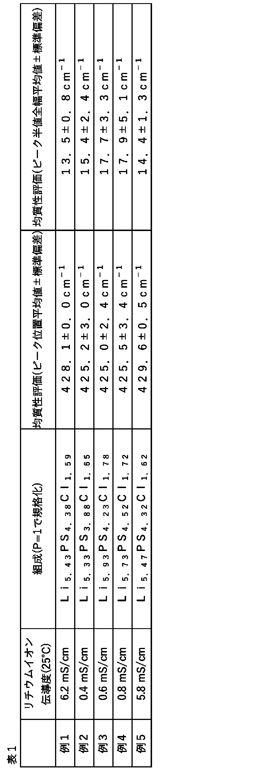
- Examples 1 and 5 are examples of this production method, and Examples 2 to 4 are comparative examples.
- the particles having the particle sizes (D50) of Li 2 S, P 2 S 5 , and LiCl of 5 ⁇ m, 10 ⁇ m, and 50 ⁇ m were used, respectively.
- Examples 4 and 5 only Li 2S having a particle size (D50) of 100 ⁇ m was used.
- the composition of the intermediate was Li 5.47 PS 4.08 Cl 1.62 , where the elemental ratio of P was 1.
- the composition analysis was carried out by ICP emission analysis measurement for P and S, atomic absorption measurement for Li, and ion chromatography measurement for Cl. (Heating and melting process)
- the obtained intermediate was placed in a heat-resistant container and heated and melted under the conditions of pressure: 1 atm and temperature: 730 ° C. for 0.5 hours. At this time, the sulfur gas obtained by heating elemental sulfur at a temperature of 350 ° C.
- Li 5.4 PS 4.4 Cl 1.6 was obtained as a sulfide-based solid electrolyte having an algyrodite-type crystal structure having a crystal phase ratio of 90 vol% or more.
- the obtained sulfide-based solid electrolyte was pulverized using a mortar to obtain a powder having a D50 of about 10 ⁇ m.
- the composition was Li 5.43 PS 4.38 Cl 1.59 with the elemental ratio of P as 1. Met.
- the crystal phase was identified by XRD measurement (device name: SmartLab manufactured by Rigaku Co., Ltd.).
- the crystal phase was a single phase of algyrodite type crystals.
- the XRD measurement result of the sulfide-based solid electrolyte of Example 1 is shown in FIG. (Homogeneity evaluation) Raman spectrum measurement (device name: LabRAM HR Evolution manufactured by HORIBA, Ltd.) was performed to evaluate the homogeneity of the obtained sulfide-based solid electrolyte. The measurement was carried out at any 10 points using the obtained sample powder in the form of pellets having a diameter of 1 cm.
- the (PS 4 ) 3 -Raman band (420-430 cm -1 ) peak derived from the algyrodite type crystal structure is used, and the variation in the peak wavenumber at 10 measurement points is measured (peak position mean ⁇ standard deviation). It was evaluated in the form of.
- the peak position average value is the average value of the peak wavenumbers of each spectrum. The smaller the absolute value of the standard deviation in (peak position mean value ⁇ standard deviation), the smaller the variation in the peak wave number (peak position).
- Raman spectrum measurements were performed in a non-atmospheric environment. The measurement conditions are as follows.
- Example 1 Excitation wavelength 532 nm, sample irradiation power 5 mW, objective lens 10 times, numerical aperture 0.25, confocal pinhole: 200 ⁇ m, grating: 1200 gr / mm, measurement time: 3 sec ⁇ 10 times, spot diameter: about 3 ⁇ m. The measurements were performed without exposure to the atmosphere. The (peak position mean ⁇ standard deviation) of Example 1 was 428.1 ⁇ 0.0 cm -1 . The Raman spectrum measurement results of the sulfide-based solid electrolyte of Example 1 are shown in Table 1 and FIG. Note that FIG.
- Lithium ion conductivity was measured at 25 ° C. by the AC impedance method (1260A impedance analyzer manufactured by Solartron, measurement frequency: 7MHz to 20Hz). The lithium ion conductivity was 6.2 ⁇ 10 -3 S / cm at 25 ° C. The measurement results are shown in Table 1.
- the composition of the intermediate was Li 5.47 PS 4.08 Cl 1.62 , where the elemental ratio of P was 1. (Heating and melting process)
- the obtained intermediate was placed in a heat-resistant container and heated and melted under the conditions of pressure: 1 atm and temperature: 730 ° C. for 0.5 hours.
- the composition was Li 5.33 PS 3.88 Cl 1.65 , where the elemental ratio of P was 1.
- the XRD measurement result of the sulfide-based solid electrolyte of Example 2 is shown in FIG. (Homogeneity evaluation)
- Raman spectrum measurement was performed in the same manner as in Example 1, and the homogeneity of the obtained sulfide-based solid electrolyte was evaluated.
- the (peak position mean ⁇ standard deviation) of Example 2 was 425.2 ⁇ 3.0 cm -1 .
- the Raman spectrum measurement results of the sulfide-based solid electrolyte of Example 2 are shown in Table 1 and FIG. FIG.
- Lithium ion conductivity was measured at 25 ° C. by the AC impedance method in the same manner as in Example 1. The lithium ion conductivity was 0.4 ⁇ 10 -3 S / cm at 25 ° C. The measurement results are shown in Table 1.
- the obtained intermediate was placed in a heat-resistant container and heated and melted under the conditions of pressure: 1 atm and temperature: 750 ° C. for 0.5 hours.
- the sulfur gas obtained by heating elemental sulfur at a temperature of 350 ° C. is supplied so that the partial pressure of the sulfur gas becomes 0.1 atm while accommodating N 2 as a carrier gas, and contains a sulfur element.
- a gas atmosphere was obtained, and sulfur was introduced into the melt by heating and melting in this gas atmosphere.
- the content of sulfur gas in the gas atmosphere containing sulfur element was 0.1 vol%.
- Example 5 (Evaluation of homogeneity, evaluation of lithium ion conductivity) Further, Raman spectrum measurement was performed in the same manner as in Example 1, and the homogeneity of the obtained sulfide-based solid electrolyte was evaluated. The (peak position mean ⁇ standard deviation) of Example 5 was 429.6 ⁇ 0.5 cm -1 . Lithium ion conductivity was measured at 25 ° C. by the AC impedance method in the same manner as in Example 1. The lithium ion conductivity was 5.8 ⁇ 10 -3 S / cm at 25 ° C.
- Table 1 shows the compositions, lithium ion conductivity evaluation results, and homogeneity evaluation results of the sulfide-based solid electrolytes of Examples 1 to 5.
- Table 1 shows (peak position mean value ⁇ standard deviation) and (peak half-value full width mean value ⁇ standard deviation) as results of homogeneity evaluation.
- Examples 1 and 5 the variation in the peak wave number (peak position) and the peak half-value full width of the Raman spectrum is small in the homogeneity evaluation, and an algyrodite type crystal can be obtained as a highly homogeneous sulfide-based solid electrolyte. , Lithium ion conductivity was also high.
- Examples 2 to 4 as comparative examples only a sulfide-based solid electrolyte having low homogeneity was obtained, and the lithium ion conductivity was also low.
- the particle size (D50) of a solid electrolyte used in an all-solid-state lithium-ion secondary battery is generally 1 to 5 ⁇ m.
- the analysis region of the Raman spectrum in the above-mentioned homogeneity evaluation corresponds to a region having the same size as one particle having such a particle size or slightly larger than one particle. That is, it can be said that the result of comparing the measured values of each measurement point in the above-mentioned homogeneity evaluation is the comparison of the measured values of the region corresponding to approximately one particle of the target solid electrolyte powder.
- the small variation in the measured values at each measurement point means that the solid electrolyte powder is homogeneous at the micron level even when crushed into a solid electrolyte powder, that is, the particles constituting the solid electrolyte powder are more homogeneous with each other.
- the sulfide-based solid electrolyte of the present invention is excellent in terms of lithium ion conductivity, and it is considered that the battery characteristics can be improved when used in an all-solid-state lithium ion secondary battery.
- the solid electrolyte powder is an aggregate of particles that are inhomogeneous to each other, there are particles in the solid electrolyte powder that are more or less inferior in terms of lithium ion conductivity. It is considered that such particles do not conduct lithium ions well when they come into contact with active materials, other solid electrolyte particles, and the like.
Landscapes
- Chemical & Material Sciences (AREA)
- Engineering & Computer Science (AREA)
- Manufacturing & Machinery (AREA)
- Chemical Kinetics & Catalysis (AREA)
- Electrochemistry (AREA)
- General Chemical & Material Sciences (AREA)
- Inorganic Chemistry (AREA)
- Organic Chemistry (AREA)
- General Physics & Mathematics (AREA)
- Condensed Matter Physics & Semiconductors (AREA)
- Physics & Mathematics (AREA)
- Materials Engineering (AREA)
- Secondary Cells (AREA)
- Conductive Materials (AREA)
Abstract
Description
従来、リチウムイオン二次電池においては液体の電解質が使用されてきたが、液漏れや発火等が懸念され、安全設計のためにケースを大型化する必要があった。また、電池寿命の短さ、動作温度範囲の狭さについても改善が望まれていた。
[1]リチウム元素、硫黄元素およびリン元素を含む原料を加熱処理して中間体を得ることと、
硫黄元素を含むガス雰囲気下で前記中間体を加熱溶融することと、を含む、
硫化物系固体電解質の製造方法。
[2]前記加熱処理において、前記原料を加熱する温度が250~500℃の範囲である、前記1に記載の硫化物系固体電解質の製造方法。
[3]前記中間体を得る際に、前記原料から揮散する硫黄元素を含む成分を回収することをさらに含み、
前記硫黄元素を含むガスの少なくとも一部として、前記硫黄元素を含む成分に由来するガスを用いる、前記1または2に記載の硫化物系固体電解質の製造方法。
[4]前記原料が、金属リチウム、硫化リチウム、炭酸リチウム、硫酸リチウム、酸化リチウムおよび水酸化リチウムからなる群から選ばれる1以上を含む、前記1~3のいずれか1に記載の硫化物系固体電解質の製造方法。
[5]前記中間体がLi4P2S6およびLi3PS4の少なくとも一方を含む、前記1~4のいずれか1に記載の硫化物系固体電解質の製造方法。
[6]前記原料がさらにハロゲン元素を含む、前記1~5のいずれか1に記載の硫化物系固体電解質の製造方法。
[7]前記原料が、塩化リチウム、臭化リチウムおよびヨウ化リチウムからなる群から選ばれる1以上を含む、前記1~6のいずれか1に記載の硫化物系固体電解質の製造方法。
[8]得られる硫化物系固体電解質がアルジロダイト型結晶構造を有する、前記1~7のいずれか1に記載の硫化物系固体電解質の製造方法。
[9]前記加熱溶融で得られた融液を冷却して固体を得ることをさらに含む硫化物系固体電解質の製造方法であって、前記融液は結晶核となる化合物を0.01質量%以上含み、前記固体は結晶相を含む硫化物系固体電解質である、前記1~8のいずれか1に記載の硫化物系固体電解質の製造方法。
[10]前記加熱溶融により得られた融液を急冷して固体を得ることをさらに含む、前記1~8のいずれか1に記載の硫化物系固体電解質の製造方法。
[11]前記急冷において、冷却速度が10℃/sec以上であり、前記融液における結晶核となる化合物の割合は1質量%以下である、前記10に記載の硫化物系固体電解質の製造方法。
[12]前記固体を再加熱処理することをさらに含む、前記9~11のいずれか1に記載の硫化物系固体電解質の製造方法。
[13]スポット径3μm、測定点の数を10としてラマンスペクトル測定をした際に、前記測定点ごとの、350cm-1~500cm-1におけるP-S結合由来のピークのピーク位置の標準偏差が2cm-1以内である、硫化物系固体電解質。
本発明の実施形態に係る硫化物系固体電解質の製造方法(以下、本製造方法と称することがある。)は、リチウム元素、硫黄元素およびリン元素を含む原料を加熱処理して中間体を得る工程(中間体合成工程)と、硫黄元素を含むガス雰囲気下で中間体を加熱溶融する工程(加熱溶融工程)と、を含む。
また、本製造方法は、さらに加熱溶融で得られた融液を冷却する工程(冷却工程)や、冷却工程により得られた固体を再加熱処理する工程(再加熱工程)、粉砕工程、乾燥工程等、適宜その他の工程を含んでもよい。以下、各工程について説明する。
本製造方法は、リチウム元素、硫黄元素およびリン元素を含む原料を加熱処理して中間体を得る中間体合成工程を含む。
本製造方法の原料は、リチウム元素(Li)、硫黄元素(S)およびリン元素(P)を含む。このような原料としては、Li単体やLiを含む化合物といったLiを含む物質(成分)、S単体やSを含む化合物といったSを含む物質(成分)、P単体やPを含む化合物といったPを含む物質(成分)等を適宜組み合わせて使用できる。Liを含む化合物、Sを含む化合物およびPを含む化合物は、Li、SおよびPから選ばれる2以上をともに含む化合物であってもよい。例えば、Sを含む化合物およびPを含む化合物を兼ねる化合物として、五硫化二リン(P2S5)等が挙げられる。
一方で、硫化リチウムは高価であるため、硫化物系固体電解質の製造コストを抑える観点からは、硫化リチウム以外のリチウム化合物や、金属リチウム等を用いることが好ましい。具体的にはこの場合、原料はLiを含む物質として、金属リチウム、炭酸リチウム(Li2CO3)、硫酸リチウム(Li2SO4)、酸化リチウム(Li2O)および水酸化リチウム(LiOH)からなる群から選ばれる1以上を含むことが好ましい。これらの物質は単独で用いてもよく、2種以上を組み合わせて用いてもよい。
ハロゲン元素を含む化合物が原料に含まれる場合、加熱処理して中間体を得る際に、ハロゲン元素を含む化合物は反応せずに、そのまま中間体に含まれる場合がある。
これらの化合物の添加量は、原料または中間体の全量に対し0.1重量%以上が好ましく、0.5重量%以上がより好ましい。また添加量は、50重量%以下が好ましく、40重量%以下がより好ましい。
また、原料は、後述する結晶核となる化合物を含んでいてもよい。
上記のリチウム元素、硫黄元素およびリン元素を含む原料を加熱処理して中間体を得る。加熱処理の具体的な方法は特に限定されないが、例えば耐熱性の容器に原料を入れ、加熱炉で加熱する方法が挙げられる。耐熱性の容器としては、特に限定されないが、カーボン製の耐熱容器、石英、石英ガラス、ホウケイ酸塩ガラス、アルミノシリケートガラス、アルミナ、ジルコニア、ムライト等の酸化物を含有した耐熱容器、窒化ケイ素、窒化ホウ素などの窒化物を含有した耐熱容器、炭化ケイ素などの炭化物を含有した耐熱容器等が挙げられる。また、これらの耐熱性容器は、上記の材質でバルクが形成されていてもよいし、カーボン、酸化物、窒化物、炭化物等の層が形成された容器であってもよい。
保持時間としては、1分以上が好ましく、5分以上がより好ましく、10分以上がさらに好ましく、15分以上がよりさらに好ましく、20分以上が特に好ましい。上記の好ましい温度で加熱した場合でも、保持時間が十分でない場合には、反応の進行が不十分となりやすく、本製造方法の効果が得られるような中間体を得にくいと考えられる。保持時間を1分以上することで、反応が進行して中間体を得られる条件となり、好ましい。保持時間は、原料中のP2S5等の沸点の低い成分の揮散抑制の観点からは600分以下が好ましく、500分以下がより好ましい。
本明細書において、原料の粒度(D50)とは、Microtrac社製 レーザー回折粒度分布測定機 MT3300EXIIを用いて粒度分布を測定し、得られた体積基準粒度分布のチャートから求められるメジアン径(D50)をいう。
この反応を本質的に早めるためには、原料の粒度を小さくすること、原料が含有する粒子の表面の酸化物層をエッチングなどにより可能な限り取り除くあるいは改質すること、粒子を多孔化すること、原料の混合条件を調整し、原料の均質性を向上すること等により、原料が含有する粒子同士の反応性を高めることが好ましい。特に、この反応においては、P2S5が最初に反応する相手であるLi2Sの粒度が中間体形成反応に影響しやすい。したがって、中間体形成反応を促進する観点からは、原料において、Li2S又はLi2Sを得る前段階のLiを含む物質(化合物等)の粒度を細かくすることが好ましい。また、Li2Sの表面の結晶性を低くすることや、微粒化以外の表面積を大きくする処理なども上記観点で効果があると考えられる。また、硫黄元素を含んだガス雰囲気中でLi2SとP2S5を反応させることも、中間体形成反応を促進することに寄与すると考えられる。
加熱溶融工程において、硫黄元素を含むガス雰囲気下で上述の中間体を加熱溶融する。なお、本工程において加熱溶融される中間体とは、必要に応じ、複数種の中間体が混合された中間体組成物や、中間体にさらに他の物質(化合物等)が添加された中間体組成物等であってもよい。
硫黄元素を含むガスは、硫黄ガス、硫化水素ガス、二硫化炭素ガス等の硫黄元素を含む気体化合物のみから構成されてもよいし、コストを抑制する観点、キャリアガスとして硫黄成分の搬送に使用する観点等からはN2ガス、アルゴンガス、ヘリウムガス等の不活性ガスを含むことも好ましい。また硫黄元素を含むガスは、本製造方法の効果を阻害しない範囲であれば、硫黄源などに由来する不純物を含んでいてもよい。
製造コストの観点や、目的の硫化物系固体電解質を高収量で得る観点から、本製造方法は中間体合成工程において、原料から揮散する硫黄元素を含む成分を回収する工程をさらに含み、加熱溶融工程において、硫黄元素を含むガスの少なくとも一部として、回収した硫黄元素を含む成分に由来するガスを用いることが好ましい。
本製造方法は、加熱溶融により得られた融液を冷却して固体を得る工程をさらに含むことが好ましい。冷却は公知の方法で行えばよく、その方法は特に限定されない。
ここで硫化物系固体電解質に含有される結晶とは、好ましくはイオン伝導性結晶である。イオン伝導性結晶とは、具体的には、リチウムイオン伝導度が10-4S/cmより大きく、より好ましくは10-3S/cmより大きい結晶である。
非晶質の硫化物系固体電解質または非晶質相を含む硫化物系固体電解質は、加熱処理(ポストアニール)することで、高温結晶化を促進できる。本製造方法は、冷却工程において得られた固体が非晶質の硫化物系固体電解質または非晶質相を含む硫化物系固体電解質である場合、固体を再加熱処理することをさらに含んでもよい。また、硫化物系固体電解質結晶を含んだ硫化物系固体電解質を再加熱処理することで、結晶構造内のイオンを再配列させ、リチウムイオン伝導度を高めることもできる。なお、本工程における再加熱処理とは、冷却工程にて冷却して得られた固体を結晶化のために加熱処理すること、および結晶構造内のイオンを再配列させることの少なくとも一方をいう。以下、これらの非晶質の硫化物系固体電解質または非晶質相を含む硫化物系固体電解質の熱処理を結晶化処理も含めて、再加熱処理と称する。
本製造方法は原料や中間体の種類および混合比の調節が可能であり、さらには中間体を得ることと、硫黄元素を含むガス雰囲気下で加熱溶融を行うこととを含むので組成制御性に優れる。そのため本製造方法では種々の硫化物系固体電解質を製造できる。本製造方法で得られる硫化物系固体電解質としては、例えばLi10GeP2S12等のLGPS型結晶構造を有する硫化物系固体電解質、Li6PS5Cl、Li5.4PS4.4Cl1.6およびLi5.4PS4.4Cl0.8Br0.8等のアルジロダイト型結晶構造を有する硫化物系固体電解質、Li-P-S-Ha系(Haはハロゲン元素から選ばれる少なくとも一つの元素を表す)の結晶化ガラス、ならびにLi7P3S11等のLPS結晶化ガラス等が挙げられる。
硫化物系固体電解質が結晶相を含む場合、硫化物系固体電解質に含有される結晶は、好ましくはイオン伝導性結晶である。イオン伝導性結晶とは、具体的には、リチウムイオン伝導度が10-4S/cmより大きく、より好ましくは10-3S/cmより大きい結晶である。結晶相は、リチウムイオン伝導度の観点からはアルジロダイト型結晶相であることがより好ましい。
硫化物系固体電解質の組成の均質性を評価する際の好ましいラマンスペクトル測定の条件として、例えばスポット径3μm、測定点の数を10とすることが挙げられる。スポット径を3μmとすることで、ラマンスペクトル測定における分析領域が、硫化物系固体電解質の組成の均質性をミクロレベルで評価するのに適した大きさとなる。
PS4 3-に由来するピークの位置も組成系によって異なるが、典型的には、PS4 3-に由来するピークは350cm-1~500cm-1の間に含まれるP-S結合由来のピークである。例えば、アルジロダイト型結晶構造を有する硫化物系固体電解質においては、かかるピークは420~430cm-1の間に含まれる。以降、本明細書においてピーク位置のばらつきやピークの半値全幅のばらつきとは、PS4 3-に由来するピークについて確認されるものをいう。
例えば、本製造方法により得られる硫化物系固体電解質について、スポット径3μm、測定点の数を10としてラマンスペクトル測定をした際に、前記測定点ごとの、350cm-1~500cm-1におけるP-S結合由来のピークのピーク位置の標準偏差が、2cm-1以内であることが好ましく、より好ましくは1cm-1以内であり、より好ましくは、0.5cm-1以内である。
例えば、本製造方法により得られる硫化物系固体電解質について、スポット径3μm、測定点の数を10としてラマンスペクトル測定をした際に、前記測定点ごとの、350cm-1~500cm-1におけるP-S結合由来のピークの半値全幅の標準偏差が、2cm-1以内であることが好ましく、より好ましくは1.5cm-1以内である。
なお、各例で原料に用いた物質の粒度について、例1~3では、Li2S、P2S5、LiClの粒度(D50)がそれぞれ、5μm、10μm、50μmのものを用いた。例4、5では、Li2Sだけ粒度(D50)が100μmのものを用いた。
(中間体合成工程)
Li2S、P2S5、LiClの各原料粉末を1.9:0.5:1.6(mol比)になるように調合した。この原料粉末を耐熱性の容器に入れ、30g試験炉に入れ、露点-50℃の窒素雰囲気下、圧力:1気圧、温度:300℃(昇温速度5℃/分)の条件で0.5時間保持することで加熱処理し、中間体を得た。
得られた中間体について、XRD測定(装置名:株式会社リガク製SmartLab)を行ったところ、P2S5の結晶ピークは確認されなかった。また組成分析の結果、中間体の組成は、Pの元素比を1として、Li5.47PS4.08Cl1.62であった。なお組成分析は、PとSはICP発光分析測定により、Liは原子吸光測定により、Clはイオンクロマトグラフィ測定により行った。
(加熱溶融工程)
得られた中間体を耐熱性の容器に入れ、圧力:1気圧、温度:730℃の条件で0.5時間加熱溶融した。このとき、単体硫黄を350℃の温度で加熱して得られた硫黄ガスを、N2をキャリアガスとして同伴させながら硫黄ガスの分圧が0.1atmとなるように供給し、硫黄元素を含むガス雰囲気を得て、このガス雰囲気下で加熱溶融を行うことで融液に硫黄を導入した。硫黄元素を含むガス雰囲気における硫黄ガスの含有量は0.1vol%であった。
(冷却工程)
その後、冷却速度10~1000℃/secで冷却し非晶質相とアルジロダイト型結晶相を含有した硫化物系固体電解質として固体を得た。
(再加熱工程)
次いで、この固体を窒素ガス雰囲気下、450℃で1時間再加熱処理し、結晶化した。これにより結晶相の割合が90vol%以上のアルジロダイト型結晶構造を有する硫化物系固体電解質としてLi5.4PS4.4Cl1.6を得た。得られた硫化物系固体電解質について、乳鉢を用いて粉砕処理を行い、D50が約10μmの粉末を得た。
粉砕後の硫化物系固体電解質粉末をサンプルとして、中間体合成工程と同様に組成分析を行った結果、組成は、Pの元素比を1として、Li5.43PS4.38Cl1.59であった。結晶相は、XRD測定(装置名:株式会社リガク製SmartLab)により同定した。XRD測定の結果、結晶相はアルジロダイト型の結晶の単一相であった。例1の硫化物系固体電解質のXRD測定結果を図1に示す。
(均質性評価)
またラマンスペクトル測定(装置名:株式会社堀場製作所製LabRAM HR Evolution)を行い、得られた硫化物系固体電解質の均質性を評価した。測定は、得られたサンプル粉末を直径1cmのペレット状にしたものを用い、任意の10点について行った。ばらつきの指標として、アルジロダイト型結晶構造由来の(PS4)3-のラマンバンド(420~430cm-1)ピークを用い、測定点10点におけるピーク波数のばらつきを(ピーク位置平均値±標準偏差)の形で評価した。ピーク位置平均値とは、各スペクトルのピーク波数の平均値である。(ピーク位置平均値±標準偏差)における標準偏差の絶対値が小さいほど、ピーク波数(ピーク位置)のばらつきが小さいことを示す。
なお、ラマンスペクトル測定は大気非曝露環境で実施した。測定条件は次の通りである。励起波長532nm、サンプル照射時パワー5mW、対物レンズ10倍、開口数0.25、共焦点ピンホール:200μm、グレーティング:1200gr/mm、測定時間:3sec×10回、スポット径:約3μm。測定は大気非暴露の状態で実施した。
例1の(ピーク位置平均値±標準偏差)は、428.1±0.0cm-1であった。例1の硫化物系固体電解質のラマンスペクトル測定結果を表1および図2に示す。なお、図2は測定点10点の各点におけるラマンスペクトルを重ねた図であり、ピーク位置のばらつきを分かりやすくするため、縦軸の強度で規格化したものである。
(リチウムイオン伝導度評価)
交流インピーダンス法(ソーラートロン社製 1260Aインピーダンスアナライザー、測定周波数:7MHz~20Hz)によりリチウムイオン伝導度を25℃で測定した。リチウムイオン伝導度は、25℃において6.2×10⁻³S/cmであった。測定結果を表1に示す。
(中間体合成工程)
Li2S、P2S5、LiClの各原料粉末を1.9:0.5:1.6(mol比)になるように調合した。この原料粉末を耐熱性の容器に入れ、30g試験炉に入れ、露点-50℃の窒素雰囲気下、圧力:1気圧、温度:300℃(昇温速度5℃/分)の条件で0.5時間保持することで加熱処理し、中間体を得た。
得られた中間体について、XRD測定(装置名:株式会社リガク製SmartLab)を行うと、P2S5の結晶ピークは確認されなかった。また例1と同様に組成分析を行った結果、中間体の組成は、Pの元素比を1として、Li5.47PS4.08Cl1.62であった。
(加熱溶融工程)
得られた中間体を耐熱性の容器に入れ、圧力:1気圧、温度:730℃の条件で0.5時間加熱溶融した。
(冷却工程)
その後、冷却速度10~1000℃/secで冷却し、非晶質相とアルジロダイト型結晶相と不純物相を含有した硫化物系固体電解質として固体を得た。
(再加熱工程)
次いで、この固体を窒素ガス雰囲気下、450℃で1時間再加熱処理した。得られた硫化物系固体電解質について、乳鉢を用いて粉砕処理を行い、D50が約10μmの粉末を得た。
粉砕後の硫化物系固体電解質粉末について、例1と同様に、組成分析およびXRD測定を行った。組成は、Pの元素比を1として、Li5.33PS3.88Cl1.65であった。また、例2の硫化物系固体電解質のXRD測定結果を図3に示す。
(均質性評価)
また例1と同様にラマンスペクトル測定を行い、得られる硫化物系固体電解質の均質性を評価した。例2の(ピーク位置平均値±標準偏差)は、425.2±3.0cm-1であった。例2の硫化物系固体電解質のラマンスペクトル測定結果を表1および図4に示す。図4は測定点10点の各点におけるラマンスペクトルを重ねた図であり、ピーク位置のばらつきを分かりやすくするため、縦軸の強度で規格化したものである。
(リチウムイオン伝導度評価)
例1と同様に交流インピーダンス法によりリチウムイオン伝導度を25℃で測定した。リチウムイオン伝導度は25℃において0.4×10⁻³S/cmであった。測定結果を表1に示す。
(加熱溶融工程)
Li2S、P2S5、LiClの各原料粉末を1.9:0.5:1.6(mol比)になるように調合した。この原料粉末を耐熱性の容器に入れ、30g試験炉に入れ、硫黄の粉末を3g容器に添加した後、露点-50℃の窒素雰囲気下、圧力:1気圧、温度:950℃(昇温速度30℃/分)の条件で0.5時間加熱溶融した。
(冷却工程)
その後、冷却速度10~1000℃/secで冷却し、非晶質相とアルジロダイト型結晶相と不純物相を含有した硫化物系固体電解質として固体を得た。
(再加熱工程)
次いで、この固体を窒素ガス雰囲気下、450℃で1時間再加熱処理した。得られた硫化物系固体電解質について、乳鉢を用いて粉砕処理を行い、D50が約10μmの粉末を得た。
粉砕後の硫化物系固体電解質粉末について、組成分析を行ったところ、Pの元素比を1として、Li5.93PS4.23Cl1.78であった。
(均質性評価、リチウムイオン伝導度評価)
また例1と同様にラマンスペクトル測定を行い、得られる硫化物系固体電解質の均質性を評価した。例3の(ピーク位置平均値±標準偏差)は、425.0±2.4cm-1であった。
例1と同様に交流インピーダンス法によりリチウムイオン伝導度を25℃で測定した。リチウムイオン伝導度は25℃において0.6×10⁻³S/cmであった。
(加熱溶融工程)
Li2S、P2S5、LiClの各原料粉末を1.9:0.5:1.6(mol比)になるように調合した。この原料粉末を耐熱性の容器に入れ、30g試験炉に入れ、硫黄の粉末を3g容器に添加した後、露点-50℃の窒素雰囲気下、圧力:1気圧、温度:750℃(昇温速度30℃/分)の条件で0.5時間加熱溶融した。
(冷却工程)
その後、冷却速度10~1000℃/secで冷却し、非晶質相とアルジロダイト型結晶相と不純物相を含有した硫化物系固体電解質として固体を得た。
(再加熱工程)
次いで、この固体を窒素ガス雰囲気下、450℃で1時間再加熱処理した。得られた硫化物系固体電解質について、乳鉢を用いて粉砕処理を行い、D50が約10μmの粉末を得た。
粉砕後の硫化物系固体電解質粉末について、組成分析を行ったところ、Pの元素比を1として、Li5.73PS4.52Cl1.72であった。
(均質性評価、リチウムイオン伝導度評価)
また例1と同様にラマンスペクトル測定を行い、得られる硫化物系固体電解質の均質性を評価した。例4の(ピーク位置平均値±標準偏差)は、425.5±3.4cm-1であった。
例1と同様に交流インピーダンス法によりリチウムイオン伝導度を25℃で測定した。リチウムイオン伝導度は25℃において0.8×10⁻³S/cmであった。
(中間体合成工程)
Li2S、P2S5、LiClの各原料粉末を1.9:0.5:1.6(mol比)になるように調合した。この原料粉末を耐熱性の容器に入れ、30g試験炉に入れ、露点-50℃の窒素雰囲気下、圧力:1気圧、温度:300℃(昇温速度5℃/分)の条件で0.5時間保持することで加熱処理し、中間体を得た。
(加熱溶融工程)
得られた中間体を耐熱性の容器に入れ、圧力:1気圧、温度:750℃の条件で0.5時間加熱溶融した。このとき、単体硫黄を350℃の温度で加熱して得られた硫黄ガスを、N2をキャリアガスとして同伴させながら硫黄ガスの分圧が0.1atmとなるように供給し、硫黄元素を含むガス雰囲気を得て、このガス雰囲気下で加熱溶融を行うことで融液に硫黄を導入した。硫黄元素を含むガス雰囲気における硫黄ガスの含有量は0.1vol%であった。
(冷却工程)
その後、冷却速度10~1000℃/secで冷却し非晶質相とアルジロダイト型結晶相を含有した硫化物系固体電解質として固体を得た。
(再加熱工程)
次いで、この固体を窒素ガス雰囲気下、450℃で1時間再加熱処理した。得られた硫化物系固体電解質について、乳鉢を用いて粉砕処理を行い、D50が約10μmの粉末を得た。
粉砕後の硫化物系固体電解質粉末について、組成分析を行ったところ、Pの元素比を1として、Li5.47PS4.32Cl1.62であった。
(均質性評価、リチウムイオン伝導度評価)
また例1と同様にラマンスペクトル測定を行い、得られる硫化物系固体電解質の均質性を評価した。例5の(ピーク位置平均値±標準偏差)は、429.6±0.5cm-1であった。
例1と同様に交流インピーダンス法によりリチウムイオン伝導度を25℃で測定した。リチウムイオン伝導度は25℃において5.8×10⁻³S/cmであった。
したがって、各測定点の測定値のばらつきが小さいことは、粉砕して固体電解質粉末とした場合にも固体電解質粉末がミクロンレベルで均質である、すなわち固体電解質粉末を構成する粒子同士が互いにより均質であることを意味する。これにより、本発明の硫化物系固体電解質はリチウムイオン伝導性の点で優れ、全固体型リチウムイオン二次電池に用いた際に電池特性を向上できると考えられる。
一方で、固体電解質粉末が互いに不均質な粒子の集合体である場合、固体電解質粉末の中には多かれ少なかれリチウムイオン伝導性の点で劣る粒子が存在することとなる。このような粒子は活物質や他の固体電解質粒子等と接触した際にリチウムイオンをうまく伝導させられないと考えられる。
Claims (13)
- リチウム元素、硫黄元素およびリン元素を含む原料を加熱処理して中間体を得ることと、
硫黄元素を含むガス雰囲気下で前記中間体を加熱溶融することと、を含む、
硫化物系固体電解質の製造方法。 - 前記加熱処理において、前記原料を加熱する温度が250~500℃の範囲である、請求項1に記載の硫化物系固体電解質の製造方法。
- 前記中間体を得る際に、前記原料から揮散する硫黄元素を含む成分を回収することをさらに含み、
前記硫黄元素を含むガスの少なくとも一部として、前記硫黄元素を含む成分に由来するガスを用いる、請求項1または2に記載の硫化物系固体電解質の製造方法。 - 前記原料が、金属リチウム、硫化リチウム、炭酸リチウム、硫酸リチウム、酸化リチウムおよび水酸化リチウムからなる群から選ばれる1以上を含む、請求項1~3のいずれか1項に記載の硫化物系固体電解質の製造方法。
- 前記中間体がLi4P2S6およびLi3PS4の少なくとも一方を含む、請求項1~4のいずれか1項に記載の硫化物系固体電解質の製造方法。
- 前記原料がさらにハロゲン元素を含む、請求項1~5のいずれか1項に記載の硫化物系固体電解質の製造方法。
- 前記原料が、塩化リチウム、臭化リチウムおよびヨウ化リチウムからなる群から選ばれる1以上を含む、請求項1~6のいずれか1項に記載の硫化物系固体電解質の製造方法。
- 得られる硫化物系固体電解質がアルジロダイト型結晶構造を有する、請求項1~7のいずれか1項に記載の硫化物系固体電解質の製造方法。
- 前記加熱溶融で得られた融液を冷却して固体を得ることをさらに含む硫化物系固体電解質の製造方法であって、前記融液は結晶核となる化合物を0.01質量%以上含み、前記固体は結晶相を含む硫化物系固体電解質である、請求項1~8のいずれか1項に記載の硫化物系固体電解質の製造方法。
- 前記加熱溶融により得られた融液を急冷して固体を得ることをさらに含む、請求項1~8のいずれか1項に記載の硫化物系固体電解質の製造方法。
- 前記急冷において、冷却速度が10℃/sec以上であり、前記融液における結晶核となる化合物の割合は1質量%以下である、請求項10に記載の硫化物系固体電解質の製造方法。
- 前記固体を再加熱処理することをさらに含む、請求項9~11のいずれか1項に記載の硫化物系固体電解質の製造方法。
- スポット径3μm、測定点の数を10としてラマンスペクトル測定をした際に、前記測定点ごとの、350cm-1~500cm-1におけるP-S結合由来のピークのピーク位置の標準偏差が2cm-1以内である、硫化物系固体電解質。
Priority Applications (7)
| Application Number | Priority Date | Filing Date | Title |
|---|---|---|---|
| KR1020237003011A KR20230044203A (ko) | 2020-07-31 | 2021-07-30 | 황화물계 고체 전해질의 제조 방법 및 황화물계 고체 전해질 |
| EP21849673.5A EP4190743A1 (en) | 2020-07-31 | 2021-07-30 | Method for producing sulfide solid electrolyte, and sulfide solid electrolyte |
| JP2022539617A JP7452659B2 (ja) | 2020-07-31 | 2021-07-30 | 硫化物系固体電解質の製造方法及び硫化物系固体電解質 |
| CN202180050018.0A CN116171260A (zh) | 2020-07-31 | 2021-07-30 | 硫化物系固体电解质的制造方法和硫化物系固体电解质 |
| US18/159,733 US20230178799A1 (en) | 2020-07-31 | 2023-01-26 | Method for producing sulfide solid electrolyte, and sulfide solid electrolyte |
| JP2024001902A JP2024028433A (ja) | 2020-07-31 | 2024-01-10 | 硫化物系固体電解質の製造方法及び硫化物系固体電解質 |
| JP2024001901A JP2024028432A (ja) | 2020-07-31 | 2024-01-10 | 硫化物系固体電解質の製造方法及び硫化物系固体電解質 |
Applications Claiming Priority (2)
| Application Number | Priority Date | Filing Date | Title |
|---|---|---|---|
| JP2020-130799 | 2020-07-31 | ||
| JP2020130799 | 2020-07-31 |
Related Child Applications (1)
| Application Number | Title | Priority Date | Filing Date |
|---|---|---|---|
| US18/159,733 Continuation US20230178799A1 (en) | 2020-07-31 | 2023-01-26 | Method for producing sulfide solid electrolyte, and sulfide solid electrolyte |
Publications (1)
| Publication Number | Publication Date |
|---|---|
| WO2022025268A1 true WO2022025268A1 (ja) | 2022-02-03 |
Family
ID=80036388
Family Applications (1)
| Application Number | Title | Priority Date | Filing Date |
|---|---|---|---|
| PCT/JP2021/028382 WO2022025268A1 (ja) | 2020-07-31 | 2021-07-30 | 硫化物系固体電解質の製造方法及び硫化物系固体電解質 |
Country Status (6)
| Country | Link |
|---|---|
| US (1) | US20230178799A1 (ja) |
| EP (1) | EP4190743A1 (ja) |
| JP (3) | JP7452659B2 (ja) |
| KR (1) | KR20230044203A (ja) |
| CN (1) | CN116171260A (ja) |
| WO (1) | WO2022025268A1 (ja) |
Cited By (6)
| Publication number | Priority date | Publication date | Assignee | Title |
|---|---|---|---|---|
| WO2023219067A1 (ja) * | 2022-05-13 | 2023-11-16 | Agc株式会社 | 硫化物系固体電解質粉末の製造方法及び製造装置 |
| WO2023219173A1 (ja) * | 2022-05-13 | 2023-11-16 | Agc株式会社 | 硫化物系固体電解質の製造方法及び製造装置 |
| WO2023223872A1 (ja) * | 2022-05-18 | 2023-11-23 | Agc株式会社 | 硫化物系固体電解質の製造方法及び製造装置 |
| JP7420198B1 (ja) | 2022-11-02 | 2024-01-23 | Agc株式会社 | 硫化物系固体電解質の製造方法および硫化物系固体電解質の製造装置 |
| WO2024018976A1 (ja) * | 2022-07-19 | 2024-01-25 | Agc株式会社 | 硫化物固体電解質及びその製造方法 |
| WO2024101110A1 (ja) * | 2022-11-07 | 2024-05-16 | Agc株式会社 | 硫化物固体電解質の製造方法 |
Citations (4)
| Publication number | Priority date | Publication date | Assignee | Title |
|---|---|---|---|---|
| JP2012043654A (ja) | 2010-08-19 | 2012-03-01 | Nippon Electric Glass Co Ltd | リチウムイオン伝導性材料の製造方法 |
| JP2013211171A (ja) * | 2012-03-30 | 2013-10-10 | Mitsui Mining & Smelting Co Ltd | 硫化物系固体電解質の製造方法 |
| WO2020095937A1 (ja) * | 2018-11-08 | 2020-05-14 | 三井金属鉱業株式会社 | 硫黄含有化合物、固体電解質及び電池 |
| JP2020130799A (ja) | 2019-02-22 | 2020-08-31 | 株式会社大都技研 | 遊技台 |
Family Cites Families (4)
| Publication number | Priority date | Publication date | Assignee | Title |
|---|---|---|---|---|
| JP5552802B2 (ja) | 2009-12-04 | 2014-07-16 | トヨタ自動車株式会社 | 硫化物固体電解質材料の製造方法、硫化物固体電解質材料およびリチウム電池 |
| JP5552974B2 (ja) | 2010-09-03 | 2014-07-16 | トヨタ自動車株式会社 | 硫化物固体電解質材料、硫化物固体電解質材料の製造方法およびリチウム固体電池 |
| JP6686860B2 (ja) | 2016-12-09 | 2020-04-22 | トヨタ自動車株式会社 | 硫化物固体電解質の製造方法 |
| JP6881360B2 (ja) | 2018-03-14 | 2021-06-02 | トヨタ自動車株式会社 | 被覆硫化物固体電解質の製造方法 |
-
2021
- 2021-07-30 CN CN202180050018.0A patent/CN116171260A/zh active Pending
- 2021-07-30 KR KR1020237003011A patent/KR20230044203A/ko active Search and Examination
- 2021-07-30 JP JP2022539617A patent/JP7452659B2/ja active Active
- 2021-07-30 WO PCT/JP2021/028382 patent/WO2022025268A1/ja active Application Filing
- 2021-07-30 EP EP21849673.5A patent/EP4190743A1/en active Pending
-
2023
- 2023-01-26 US US18/159,733 patent/US20230178799A1/en active Pending
-
2024
- 2024-01-10 JP JP2024001901A patent/JP2024028432A/ja active Pending
- 2024-01-10 JP JP2024001902A patent/JP2024028433A/ja active Pending
Patent Citations (4)
| Publication number | Priority date | Publication date | Assignee | Title |
|---|---|---|---|---|
| JP2012043654A (ja) | 2010-08-19 | 2012-03-01 | Nippon Electric Glass Co Ltd | リチウムイオン伝導性材料の製造方法 |
| JP2013211171A (ja) * | 2012-03-30 | 2013-10-10 | Mitsui Mining & Smelting Co Ltd | 硫化物系固体電解質の製造方法 |
| WO2020095937A1 (ja) * | 2018-11-08 | 2020-05-14 | 三井金属鉱業株式会社 | 硫黄含有化合物、固体電解質及び電池 |
| JP2020130799A (ja) | 2019-02-22 | 2020-08-31 | 株式会社大都技研 | 遊技台 |
Cited By (9)
| Publication number | Priority date | Publication date | Assignee | Title |
|---|---|---|---|---|
| WO2023219067A1 (ja) * | 2022-05-13 | 2023-11-16 | Agc株式会社 | 硫化物系固体電解質粉末の製造方法及び製造装置 |
| WO2023219173A1 (ja) * | 2022-05-13 | 2023-11-16 | Agc株式会社 | 硫化物系固体電解質の製造方法及び製造装置 |
| JP7440002B1 (ja) | 2022-05-13 | 2024-02-28 | Agc株式会社 | 硫化物系固体電解質の製造方法及び製造装置 |
| WO2023223872A1 (ja) * | 2022-05-18 | 2023-11-23 | Agc株式会社 | 硫化物系固体電解質の製造方法及び製造装置 |
| JP7415241B1 (ja) | 2022-05-18 | 2024-01-17 | Agc株式会社 | 硫化物系固体電解質の製造方法及び製造装置 |
| WO2024018976A1 (ja) * | 2022-07-19 | 2024-01-25 | Agc株式会社 | 硫化物固体電解質及びその製造方法 |
| JP7420198B1 (ja) | 2022-11-02 | 2024-01-23 | Agc株式会社 | 硫化物系固体電解質の製造方法および硫化物系固体電解質の製造装置 |
| WO2024095938A1 (ja) * | 2022-11-02 | 2024-05-10 | Agc株式会社 | 硫化物系固体電解質の製造方法および硫化物系固体電解質の製造装置 |
| WO2024101110A1 (ja) * | 2022-11-07 | 2024-05-16 | Agc株式会社 | 硫化物固体電解質の製造方法 |
Also Published As
| Publication number | Publication date |
|---|---|
| EP4190743A1 (en) | 2023-06-07 |
| US20230178799A1 (en) | 2023-06-08 |
| JP2024028433A (ja) | 2024-03-04 |
| CN116171260A (zh) | 2023-05-26 |
| KR20230044203A (ko) | 2023-04-03 |
| JPWO2022025268A1 (ja) | 2022-02-03 |
| JP7452659B2 (ja) | 2024-03-19 |
| JP2024028432A (ja) | 2024-03-04 |
Similar Documents
| Publication | Publication Date | Title |
|---|---|---|
| WO2022025268A1 (ja) | 硫化物系固体電解質の製造方法及び硫化物系固体電解質 | |
| WO2013145480A1 (ja) | 硫化物系固体電解質の製造方法 | |
| US20230246227A1 (en) | Sulfide solid electrolyte and method for manufacturing same | |
| JP6773456B2 (ja) | 無機材料の製造方法 | |
| US20240055653A1 (en) | Sulfide based solid electrolyte, solid electrolyte layer, and lithium ion secondary battery | |
| WO2022009934A1 (ja) | リチウムイオン二次電池に用いられる硫化物系固体電解質及びその製造方法、固体電解質層並びにリチウムイオン二次電池 | |
| WO2024018976A1 (ja) | 硫化物固体電解質及びその製造方法 | |
| JP7440002B1 (ja) | 硫化物系固体電解質の製造方法及び製造装置 | |
| JP7440000B2 (ja) | アルカリ金属元素及び硫黄元素を含む物質の製造方法 | |
| CN115136345A (zh) | 固态锂离子导体材料、由固态离子导体材料制成的粉末及其制备方法 | |
| JP7415241B1 (ja) | 硫化物系固体電解質の製造方法及び製造装置 | |
| WO2024095938A1 (ja) | 硫化物系固体電解質の製造方法および硫化物系固体電解質の製造装置 | |
| WO2023210604A1 (ja) | 硫化物系固体電解質の製造方法、ハロゲン化リチウム含有組成物、及び硫化リチウム含有組成物 | |
| JP7416173B1 (ja) | 硫化物系固体電解質の製造方法および硫化物系固体電解質の製造装置 | |
| WO2023145657A1 (ja) | 硫化物系固体電解質の製造方法 | |
| WO2024101110A1 (ja) | 硫化物固体電解質の製造方法 | |
| WO2023219067A1 (ja) | 硫化物系固体電解質粉末の製造方法及び製造装置 | |
| JP7420296B1 (ja) | 硫化物固体電解質粉末の製造方法およびその製造装置 | |
| JP7171896B2 (ja) | 硫化物系無機固体電解質材料の製造方法 | |
| CN115803285B (zh) | 用于锂离子二次电池的硫化物系固体电解质及其制造方法、固体电解质层以及锂离子二次电池 | |
| WO2023053609A1 (ja) | 硫化物系固体電解質及びその製造方法 | |
| CN118104026A (zh) | 硫化物系固体电解质及其制造方法 |
Legal Events
| Date | Code | Title | Description |
|---|---|---|---|
| 121 | Ep: the epo has been informed by wipo that ep was designated in this application |
Ref document number: 21849673 Country of ref document: EP Kind code of ref document: A1 |
|
| ENP | Entry into the national phase |
Ref document number: 2022539617 Country of ref document: JP Kind code of ref document: A |
|
| WWE | Wipo information: entry into national phase |
Ref document number: 2021849673 Country of ref document: EP |
|
| ENP | Entry into the national phase |
Ref document number: 2021849673 Country of ref document: EP Effective date: 20230228 |
|
| NENP | Non-entry into the national phase |
Ref country code: DE |