WO2022014395A1 - 精製方法 - Google Patents
精製方法 Download PDFInfo
- Publication number
- WO2022014395A1 WO2022014395A1 PCT/JP2021/025388 JP2021025388W WO2022014395A1 WO 2022014395 A1 WO2022014395 A1 WO 2022014395A1 JP 2021025388 W JP2021025388 W JP 2021025388W WO 2022014395 A1 WO2022014395 A1 WO 2022014395A1
- Authority
- WO
- WIPO (PCT)
- Prior art keywords
- wavelength
- infrared
- solvent
- infrared rays
- compound
- Prior art date
Links
Images

Classifications
-
- C—CHEMISTRY; METALLURGY
- C07—ORGANIC CHEMISTRY
- C07D—HETEROCYCLIC COMPOUNDS
- C07D277/00—Heterocyclic compounds containing 1,3-thiazole or hydrogenated 1,3-thiazole rings
- C07D277/02—Heterocyclic compounds containing 1,3-thiazole or hydrogenated 1,3-thiazole rings not condensed with other rings
- C07D277/20—Heterocyclic compounds containing 1,3-thiazole or hydrogenated 1,3-thiazole rings not condensed with other rings having two or three double bonds between ring members or between ring members and non-ring members
- C07D277/32—Heterocyclic compounds containing 1,3-thiazole or hydrogenated 1,3-thiazole rings not condensed with other rings having two or three double bonds between ring members or between ring members and non-ring members with hetero atoms or with carbon atoms having three bonds to hetero atoms with at the most one bond to halogen, e.g. ester or nitrile radicals, directly attached to ring carbon atoms
- C07D277/56—Carbon atoms having three bonds to hetero atoms with at the most one bond to halogen
-
- C—CHEMISTRY; METALLURGY
- C07—ORGANIC CHEMISTRY
- C07C—ACYCLIC OR CARBOCYCLIC COMPOUNDS
- C07C227/00—Preparation of compounds containing amino and carboxyl groups bound to the same carbon skeleton
- C07C227/38—Separation; Purification; Stabilisation; Use of additives
- C07C227/40—Separation; Purification
- C07C227/42—Crystallisation
-
- C—CHEMISTRY; METALLURGY
- C07—ORGANIC CHEMISTRY
- C07C—ACYCLIC OR CARBOCYCLIC COMPOUNDS
- C07C51/00—Preparation of carboxylic acids or their salts, halides or anhydrides
- C07C51/42—Separation; Purification; Stabilisation; Use of additives
- C07C51/43—Separation; Purification; Stabilisation; Use of additives by change of the physical state, e.g. crystallisation
-
- C—CHEMISTRY; METALLURGY
- C07—ORGANIC CHEMISTRY
- C07D—HETEROCYCLIC COMPOUNDS
- C07D223/00—Heterocyclic compounds containing seven-membered rings having one nitrogen atom as the only ring hetero atom
- C07D223/14—Heterocyclic compounds containing seven-membered rings having one nitrogen atom as the only ring hetero atom condensed with carbocyclic rings or ring systems
- C07D223/18—Dibenzazepines; Hydrogenated dibenzazepines
- C07D223/22—Dibenz [b, f] azepines; Hydrogenated dibenz [b, f] azepines
- C07D223/24—Dibenz [b, f] azepines; Hydrogenated dibenz [b, f] azepines with hydrocarbon radicals, substituted by nitrogen atoms, attached to the ring nitrogen atom
- C07D223/26—Dibenz [b, f] azepines; Hydrogenated dibenz [b, f] azepines with hydrocarbon radicals, substituted by nitrogen atoms, attached to the ring nitrogen atom having a double bond between positions 10 and 11
-
- C—CHEMISTRY; METALLURGY
- C30—CRYSTAL GROWTH
- C30B—SINGLE-CRYSTAL GROWTH; UNIDIRECTIONAL SOLIDIFICATION OF EUTECTIC MATERIAL OR UNIDIRECTIONAL DEMIXING OF EUTECTOID MATERIAL; REFINING BY ZONE-MELTING OF MATERIAL; PRODUCTION OF A HOMOGENEOUS POLYCRYSTALLINE MATERIAL WITH DEFINED STRUCTURE; SINGLE CRYSTALS OR HOMOGENEOUS POLYCRYSTALLINE MATERIAL WITH DEFINED STRUCTURE; AFTER-TREATMENT OF SINGLE CRYSTALS OR A HOMOGENEOUS POLYCRYSTALLINE MATERIAL WITH DEFINED STRUCTURE; APPARATUS THEREFOR
- C30B29/00—Single crystals or homogeneous polycrystalline material with defined structure characterised by the material or by their shape
- C30B29/54—Organic compounds
-
- C—CHEMISTRY; METALLURGY
- C30—CRYSTAL GROWTH
- C30B—SINGLE-CRYSTAL GROWTH; UNIDIRECTIONAL SOLIDIFICATION OF EUTECTIC MATERIAL OR UNIDIRECTIONAL DEMIXING OF EUTECTOID MATERIAL; REFINING BY ZONE-MELTING OF MATERIAL; PRODUCTION OF A HOMOGENEOUS POLYCRYSTALLINE MATERIAL WITH DEFINED STRUCTURE; SINGLE CRYSTALS OR HOMOGENEOUS POLYCRYSTALLINE MATERIAL WITH DEFINED STRUCTURE; AFTER-TREATMENT OF SINGLE CRYSTALS OR A HOMOGENEOUS POLYCRYSTALLINE MATERIAL WITH DEFINED STRUCTURE; APPARATUS THEREFOR
- C30B7/00—Single-crystal growth from solutions using solvents which are liquid at normal temperature, e.g. aqueous solutions
- C30B7/02—Single-crystal growth from solutions using solvents which are liquid at normal temperature, e.g. aqueous solutions by evaporation of the solvent
- C30B7/06—Single-crystal growth from solutions using solvents which are liquid at normal temperature, e.g. aqueous solutions by evaporation of the solvent using non-aqueous solvents
-
- B—PERFORMING OPERATIONS; TRANSPORTING
- B01—PHYSICAL OR CHEMICAL PROCESSES OR APPARATUS IN GENERAL
- B01D—SEPARATION
- B01D9/00—Crystallisation
- B01D9/0018—Evaporation of components of the mixture to be separated
- B01D9/0031—Evaporation of components of the mixture to be separated by heating
-
- C—CHEMISTRY; METALLURGY
- C07—ORGANIC CHEMISTRY
- C07B—GENERAL METHODS OF ORGANIC CHEMISTRY; APPARATUS THEREFOR
- C07B2200/00—Indexing scheme relating to specific properties of organic compounds
- C07B2200/13—Crystalline forms, e.g. polymorphs
-
- C—CHEMISTRY; METALLURGY
- C07—ORGANIC CHEMISTRY
- C07C—ACYCLIC OR CARBOCYCLIC COMPOUNDS
- C07C2601/00—Systems containing only non-condensed rings
- C07C2601/06—Systems containing only non-condensed rings with a five-membered ring
- C07C2601/08—Systems containing only non-condensed rings with a five-membered ring the ring being saturated
-
- C—CHEMISTRY; METALLURGY
- C07—ORGANIC CHEMISTRY
- C07D—HETEROCYCLIC COMPOUNDS
- C07D277/00—Heterocyclic compounds containing 1,3-thiazole or hydrogenated 1,3-thiazole rings
- C07D277/02—Heterocyclic compounds containing 1,3-thiazole or hydrogenated 1,3-thiazole rings not condensed with other rings
- C07D277/20—Heterocyclic compounds containing 1,3-thiazole or hydrogenated 1,3-thiazole rings not condensed with other rings having two or three double bonds between ring members or between ring members and non-ring members
- C07D277/22—Heterocyclic compounds containing 1,3-thiazole or hydrogenated 1,3-thiazole rings not condensed with other rings having two or three double bonds between ring members or between ring members and non-ring members with only hydrogen atoms, hydrocarbon or substituted hydrocarbon radicals, directly attached to ring carbon atoms
- C07D277/30—Radicals substituted by carbon atoms having three bonds to hetero atoms with at the most one bond to halogen, e.g. ester or nitrile radicals
Definitions
- the present invention relates to a purification method.
- Patent Document 1 discloses a method for purifying an organic compound using laser light.
- a semistable substance is selectively produced from a solution of a substance containing a stable form and a metastable form as a crystalline form
- a laser beam is irradiated into the solution to generate bubbles to generate metastable.
- Metastable crystals are selectively produced by generating shaped crystal nuclei.
- Patent Document 1 laser light irradiation is performed to generate bubbles in the solution, and attention is not paid to infrared absorption wavelength light.
- the present invention has been made to solve such a problem, and an object of the present invention is to obtain a specific crystalline form from a solution in which a compound is dissolved in a solvent.
- the purification method of the present invention A purification method for crystallizing a compound having at least one crystalline form.
- a specific infrared wavelength at which a specific crystal form is precipitated from a solution in which the compound is dissolved in a solvent is set as a target wavelength, and an infrared emitting device capable of emitting infrared rays including the target wavelength is used to prepare the target in the solution.
- the solvent is evaporated while irradiating with infrared rays including a wavelength to precipitate the specific crystal form. It is a thing.
- a specific crystal form can be precipitated from the solution in which the compound is dissolved in the solvent.
- the reason why a specific crystal form is precipitated is not clear, but it is considered as follows.
- the dissolution rate of the compound usually differs depending on the type of solvent.
- the dissolution rate is considered to be related to the ease of crystal precipitation. Further, it is considered that the higher the absorption rate of the irradiated infrared rays, the more active the thermal vibration and the less likely it is that crystal nuclei are generated. From these facts, it is considered that the conditions suitable for the precipitation of a specific crystal form are determined by the solvent for dissolving the compound and the infrared rays irradiating the solution.
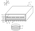
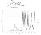
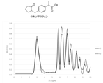
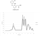
- FIG. 1 Perspective view of the purification apparatus 1 (partially shown in cross section). Partial bottom view of the infrared heater 10. Graph showing infrared absorption spectrum of febuxostat. The graph which shows the infrared absorption spectrum of loxoprofen. The graph which shows the infrared absorption spectrum of diclofenac.
- the purification method of the present embodiment is a purification method for crystallizing a compound having at least one crystal form, and a target wavelength is a specific infrared wavelength at which a specific crystal form is precipitated from a solution in which the compound is dissolved in a solvent.
- a target wavelength is a specific infrared wavelength at which a specific crystal form is precipitated from a solution in which the compound is dissolved in a solvent.
- the solvent is evaporated while irradiating the solution with infrared rays containing the target wavelength to precipitate a specific crystal form.
- the compound may have a plurality of crystal forms or may have a single crystal form.
- the crystalline form b2 is precipitated when the solvent p2 is evaporated while irradiating the solution in which the raw material of the organic compound X is dissolved in the solvent p2 with infrared rays containing the wavelength ⁇ 2 [ ⁇ m].
- infrared rays containing the solvent p1 used in the first preliminary experiment and the wavelength ⁇ 1 [ ⁇ m] are adopted.
- the infrared ray containing the solvent p1 and the wavelength ⁇ 2 [ ⁇ m] used in the second preliminary experiment is adopted.
- the infrared ray containing the solvent p2 and the wavelength ⁇ 1 [ ⁇ m] used in the third preliminary experiment is adopted. If it is desired to precipitate the crystalline form b2, the infrared ray containing the solvent p2 and the wavelength ⁇ 2 [ ⁇ m] used in the fourth preliminary experiment is adopted.
- the wavelength ⁇ 1 [ ⁇ m] or the wavelength ⁇ 2 [ ⁇ m] when setting the wavelength ⁇ 1 [ ⁇ m] or the wavelength ⁇ 2 [ ⁇ m], it is preferable to set the wavelength ⁇ 1 [ ⁇ m] or the wavelength ⁇ 2 [ ⁇ m] based on the infrared absorption spectrum of the crystal form and the dissolution rate of the raw material in the solvent, and it is preferable to set the stability of the crystal form and the crystal. It is more preferable to set based on the infrared absorption spectrum of the shape and the dissolution rate of the raw material in the solvent.
- the infrared absorption spectra of each crystal form are often different, and the absorption rate of each crystal form for a certain wavelength is often different.
- the crystal form with a high absorption rate for that wavelength becomes more active in thermal vibration than the crystal form with a low absorption rate, and crystal nuclei are less likely to be generated, so that precipitation is less likely to occur.
- the crystal form in which the crystal nuclei are easily formed differs between the solvent having a high dissolution rate of the raw material and the solvent having a slow dissolution rate.
- a crystal form having high stability often has a property of being more difficult to dissolve than other crystal forms, and therefore, there is a high possibility that it will be selectively precipitated when a solvent having a high dissolution rate is used.
- Crystal forms with low stability are likely to selectively precipitate when a solvent with a slow dissolution rate is used. Therefore, it is preferable to set the wavelength ⁇ 1 [ ⁇ m] and the wavelength ⁇ 2 [ ⁇ m] based on the infrared absorption spectrum of the crystalline form and the dissolution rate of the raw material in the solvent, and the stability of the crystalline form and the infrared absorption spectrum of the crystalline form. It is more preferable to set it based on the dissolution rate of the raw material in the solvent.
- an infrared ray having a peak at a wavelength ⁇ 1 [ ⁇ m] may be used as an infrared ray containing a wavelength ⁇ 1 [ ⁇ m]
- an infrared ray having a peak at a wavelength ⁇ 2 [ ⁇ m] may be used as an infrared ray containing a wavelength ⁇ 2 [ ⁇ m].
- the solvent q may be evaporated while irradiating the solution in which the organic compound Y is dissolved in the solvent q with infrared rays containing the wavelength ⁇ [ ⁇ m].
- infrared rays having a peak at the wavelength ⁇ [ ⁇ m] may be used as the infrared rays including the wavelength ⁇ [ ⁇ m].
- the compound that can be purified by the purification method of the present embodiment is not particularly limited, and examples thereof include febuxostat, terfenazine, indomethacin, ibuprofen, loxoprofen, caffeine, diclofenac, and carbamazepine.
- the solvent for dissolving the raw material of the compound is not particularly limited, but for example, methanol, ethanol, 1-propanol, 2-propanol (isopropanol (IPA)), 1-butanol, 2-butanol, and isobutanol.
- Turt-alcohol solvents such as butanol; nitrile solvents such as acetonitrile and propionitrile; ether solvents such as diethyl ether and tetrahydrofuran; ketone solvents such as acetone and methyl ethyl ketone; halogen solvents such as dichloromethane and chloroform; acetic acid Ester-based solvents such as ethyl and methyl acetate; aliphatic hydrocarbon-based solvents such as pentane, hexane, heptane, octane and cyclohexane; aromatic hydrocarbon-based solvents such as benzene, toluene and xylene; Examples include solvents.
- any infrared emitting device capable of emitting infrared rays including a wavelength ⁇ [ ⁇ m] can be used.
- the infrared emitting device a device having a plate-shaped radiator and a planar heater as a heat source can be used.
- the infrared emitting device it is preferable to use an infrared emitting device capable of emitting infrared rays having a peak at a wavelength ⁇ [ ⁇ m], particularly an infrared ray having a peak at a wavelength ⁇ [ ⁇ m] and having a narrow half width.
- Examples of such an infrared emitting device include a metamaterial emitter and an infrared emitting device with a filter.
- Examples of the metamaterial emitter include a MIM (Metal-Insulator-Metal) type, a microcavity type, a metaatom type, and a laminated type.
- MIM Metal-Insulator-Metal
- microcavity type for example, the one described in Reference 1 (JSME TED Newsletter, No. 74, pp.7-10, 2014) can be used. This MIM type will be described in detail later.
- As the microcavity type and the metaatom type for example, those described in Reference 2 (JSME TED Newsletter, No. 74, pp. 2-6, 2014) can be used.
- the laminated type for example, the one described in Reference 3 (ACS Cent. Sci., Vol. 5, pp319-326, 2019) can be used.
- the infrared emitting device with a filter for example, the infrared heater described in Japanese Patent No. 6442355 can be used.
- FIG. 1 is a perspective view of the purification apparatus 1, and a part thereof is shown in a cross section.
- FIG. 2 is a partial bottom view of the infrared heater 10. The left-right direction, front-back direction, and up-down direction are as shown in FIG.
- the purification device 1 is a device that precipitates a specific crystal form from the solution 22 in the flat petri dish 20 using an infrared heater 10.
- Solution 22 is a compound in which a compound having a plurality of crystalline forms is dissolved in a solvent.
- the infrared heater 10 is an example of a MIM type metamaterial emitter, and includes a heater main body 11, a structure 30, and a casing 70.
- the infrared heater 10 radiates infrared rays toward the solution 22 in the flat petri dish 20 arranged below.
- the heater main body 11 is configured as a so-called planar heater, and is a heating element 12 in which a linear member is curved in a zigzag manner, and a protective member which is an insulator that comes into contact with the heating element 12 and covers the periphery of the heating element 12. It is equipped with 13.
- Examples of the material of the heating element 12 include W, Mo, Ta, Fe—Cr—Al alloy and Ni—Cr alloy.
- Examples of the material of the protective member 13 include an insulating resin such as polyimide and ceramics.
- the heater main body 11 is arranged inside the casing 70. Both ends of the heating element 12 are connected to a pair of input terminals (not shown) attached to the casing 70, respectively. Electric power can be supplied to the heating element 12 from the outside via the pair of input terminals.
- the heater main body 11 may be a planar heater having a ribbon-shaped heating element wound around an insulator.
- the structure 30 is a plate-shaped radiator arranged below the heating element 12.
- the structure 30 has a first conductor layer 31 (metal pattern), a dielectric layer 34, a second conductor layer 35 (metal substrate), and a support substrate 37 from the lower outside to the inside of the infrared heater 10. They are stacked in this order.
- the structure 30 is arranged so as to close the opening below the casing 70.
- the first conductor layer 31 is configured as a metal pattern having a periodic structure in which metal electrodes 32 having the same shape and the same size are arranged at equal intervals on the dielectric layer 34.
- a plurality of square metal electrodes 32 are arranged on the dielectric layer 34 at intervals D1 in the left-right direction at equal intervals and at equal intervals D2 in the front-rear direction. It is configured as a metal pattern that is spaced apart and evenly spaced from each other.
- the metal electrode 32 has a shape in which the thickness (vertical height) is smaller than the horizontal width W1 (horizontal width) and the vertical width W2 (front-back width).
- D1 and D2 are equal, and W1 and W2 are equal.
- the material of the metal electrode 32 include gold and aluminum (Al).
- the metal electrode 32 is bonded to the dielectric layer 34 via an adhesive layer (not shown).
- the material of the adhesive layer include chromium (Cr), titanium (Ti), ruthenium (Ru) and the like.
- the dielectric layer 34 is a flat plate-shaped member whose upper surface is joined to the second conductor layer 35.
- the dielectric layer 34 is sandwiched between the first conductor layer 31 and the second conductor layer 35.
- the portion of the lower surface of the dielectric layer 34 where the metal electrode 32 is not arranged is a radiation surface 38 that radiates infrared rays to the object.
- Examples of the material of the dielectric layer 34 include alumina (Al 2 O 3 ) and silica (SiO 2 ).
- the second conductor layer 35 is a metal plate whose upper surface is joined to the support substrate 37 via an adhesive layer (not shown).
- an adhesive layer (not shown).
- the material of the second conductor layer 35 the same material as that of the first conductor layer 31 can be used.
- the material of the adhesive layer include chromium (Cr), titanium (Ti), ruthenium (Ru) and the like.
- the support substrate 37 is a flat plate-shaped member fixed inside the casing 70 by a fixture or the like (not shown), and supports the first conductor layer 31, the dielectric layer 34, and the second conductor layer 35.
- Examples of the material of the support substrate 37 include materials such as Si wafers and glass, which can easily maintain a smooth surface, have high heat resistance, and have low thermal warpage.
- the support substrate 37 may be in contact with the lower surface of the heater main body 11 or may be arranged vertically and vertically separated through a space without contacting the lower surface of the heater main body 11. When the support substrate 37 and the heater main body 11 are in contact with each other, they may be joined.
- Such a structure 30 functions as a metamaterial emitter having a property of selectively emitting infrared rays having a specific wavelength. This property is believed to be due to the resonance phenomenon described by Magneticpolariton.
- the magnetic polariton is a resonance phenomenon in which a strong electromagnetic field confinement effect is obtained in the dielectric (dielectric layer 34) between the upper and lower two conductors (first conductor layer 31 and second conductor layer 35). be.
- the portion of the dielectric layer 34 sandwiched between the second conductor layer 35 and the metal electrode 32 becomes the radiation source of infrared rays.
- the infrared rays emitted from the radiation source go around the metal electrode 32 and are radiated to the surrounding environment from the portion of the dielectric layer 34 where the metal electrode 32 is not arranged (that is, the radiation surface 38).
- the resonance wavelength is adjusted by adjusting the materials of the first conductor layer 31, the dielectric layer 34 and the second conductor layer 35, and the shape and periodic structure of the first conductor layer 31. Can be done.
- the infrared rays emitted from the radiation surface 38 of the structure 30 exhibit a characteristic that the emissivity of infrared rays having a specific wavelength is increased.
- the above-mentioned material so as to have the property of radiating infrared rays having a maximum peak of 0.7 or more (preferably 0.8 or more) and an emissivity of 0.7 or more (preferably 0.8 or more) from the radiation surface 38 at 5 ⁇ m or less, more preferably 1.0 ⁇ m or less).
- the shape and periodic structure are adjusted.
- the structure 30 has a characteristic of emitting infrared rays having a steep maximum peak having a relatively small half-value width and a relatively high emissivity.
- the half width is not particularly limited, but is preferably 2.0 ⁇ m or less, more preferably 1.5 ⁇ m or less, still more preferably 1.0 ⁇ m or less.
- the casing 70 has a substantially rectangular parallelepiped shape with a space inside and an open bottom surface.
- the heater main body 11 and the structure 30 are arranged in the space inside the casing 70.
- the casing 70 is made of metal (for example, SUS or aluminum) so as to reflect infrared rays emitted from the heating element 12.
- a flat petri dish 20 containing the solution 22 is placed at a position below the first conductive layer 31 of the infrared heater 10.
- the solution 22 is the organic compound X dissolved in the solvent p1.
- electric power is supplied to both ends of the heating element 12 from a power source (not shown) via an input terminal.
- the electric power is supplied so that the temperature of the heating element 12 becomes a preset temperature (for example, several hundred ° C., although not particularly limited).
- a preset temperature for example, several hundred ° C., although not particularly limited.
- energy is transferred to the surroundings by one or more of the three forms of heat transfer of conduction, convection, and radiation, and the structure 30 is heated.
- the structure 30 rises to a predetermined temperature, becomes a secondary radiator, and emits infrared rays.
- a predetermined wavelength ⁇ 1 [ ⁇ m] is set as the target wavelength, and infrared rays having a peak at the wavelength ⁇ 1 [ ⁇ m] are set so as to be emitted from the structure 30.
- the distances D1 and D2 of the metal electrodes 32 of the structure 30 and the width W1 of the metal electrodes 32 are such that the infrared rays emitted from the structure 30 become infrared rays having a peak at a predetermined wavelength ⁇ 1 [ ⁇ m].
- W2 and the period ⁇ 1, ⁇ 2 of the metal pattern are set.
- the solvent p1 of the solution 22 evaporates with the passage of time, and finally the crystal of the organic compound X having the crystal form a1 is selectively selected. Precipitate in.
- the infrared heater 10 is designed to mainly emit infrared rays of a target wavelength, it is difficult to exclude all radiation other than the target wavelength in the infrared radiation of the structure 30, and the atmosphere is the same. Then, convection radiation from each part of the heater to the surroundings is also predicted. Therefore, when constructing an actual process, various considerations should be given to the shape of the device and the like so that the temperature of the raw material and the like does not rise excessively due to the accompanying heat flow.
- the purification method of the present embodiment described in detail above a specific crystal form is precipitated from the solution in which the compound is dissolved by adjusting the solvent for dissolving the compound and the peak wavelength of the infrared rays irradiating the solution.
- the MIM type infrared heater 10 since the MIM type infrared heater 10 is used, it can be designed so that the peak wavelength of the emitted infrared rays matches the target wavelength with high accuracy.
- the first conductor layer 31 of the infrared heater 10 is configured as a metal pattern having a periodic structure in which metal electrodes 32 having the same shape and the same size are arranged at equal intervals from each other.
- the infrared heater 10 changes the peak wavelength of infrared rays emitted according to the horizontal width W1 and the vertical width W2 of the metal electrode 32.
- the horizontal width W1 and the vertical width W2 of the metal electrode 32 can be accurately manufactured according to the design values, for example, by drawing with a well-known electron beam drawing device and lifting off. Therefore, the work of adjusting the peak wavelength of the infrared rays radiated from the infrared heater 10 to the target wavelength can be performed relatively easily and accurately.
- the metal electrode 32 has a rectangular shape, but it may have a circular shape.
- the diameter of the circular metal electrode 32 corresponds to the horizontal width W1 and the vertical width W2.
- the petri dish was placed on a heating stage, and the time from the time when the petri dish was placed to the time when it was confirmed by a stereomicroscope that there was no undissolved residue of febuxostat in the solvent was defined as the dissolution time.
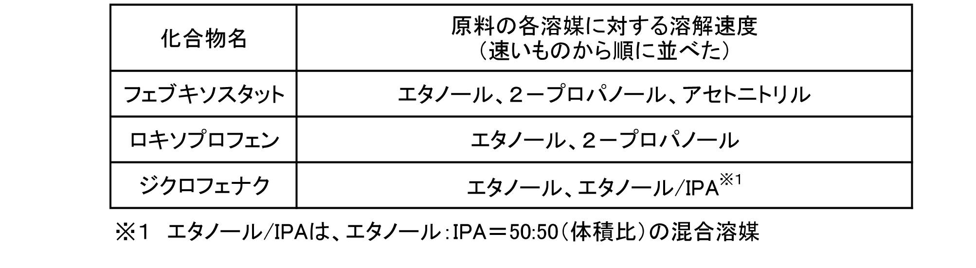
- the dissolution time As a result, ethanol, 2-propanol, and acetonitrile were obtained in order from the one with the shortest dissolution time (in other words, the one with the fastest dissolution rate). The results are shown in Table 1.
- Febuxostat is known to have a plurality of crystal forms F1, F2, Q, H1.
- a graph of the infrared absorption spectrum of each crystal form is shown in FIG.
- Loxoprofen is known to have crystalline forms F1 and F2.
- a graph of the infrared absorption spectrum of each crystal form is shown in FIG.
- Diclofenac is known to have crystalline forms F1 and F2.
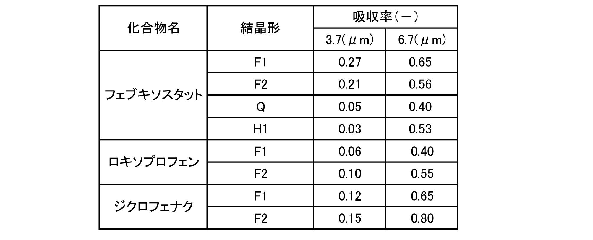
- a graph of the infrared absorption spectrum of each crystal form is shown in FIG. Table 2 shows the absorption rates of febuxostat, loxoprofen, and diclofenac in the infrared absorption spectra of each crystal form at wavelengths of 3.7 ⁇ m and 6.7 ⁇ m.
- Example 1 Weigh 25 mg of febuxostat (product code F0847, Tokyo Chemical Industry) into a flat petri dish ( ⁇ 32 mm ⁇ 16 mm), add 1 mL of ethanol (Kanto Chemical), and heat on a hot plate adjusted to 80 ° C for 2 minutes. A test sample was prepared by dissolving with light stirring. The solvent was evaporated and crystals were precipitated by radiating the test sample with infrared rays having a wavelength of 3.7 ⁇ m (here, infrared rays having a peak at a wavelength of 3.7 ⁇ m) (radiation source temperature 400 ° C.) for 30 minutes. Infrared rays were radiated using the MIM type infrared heater 10.
- the height h of the first conductor layer 31 (metal electrode 32) made of Au is 100 nm
- the thickness d of the dielectric layer 34 made of Al 2 O 3 is 100 nm
- the height f of the second conductor layer 35 made of Au is 200 nm.
- the width W1 and length W2 of the metal electrode 32 are set to 840 nm
- the intervals D1 and D2 are set to 1160 nm
- the periods ⁇ 1 and ⁇ 2 are set to 2000 nm
- infrared rays (half-value width 0.5 ⁇ m) having a peak at a wavelength of 3.7 ⁇ m are emitted. rice field.
- the crystal form of the precipitated crystal was identified by XRD analysis, the crystal form was F1.
- XRD analysis was performed using an X-ray diffractometer (product names: Ultra IV, Rigaku).
- Example 2 A test sample was prepared in the same manner as in Example 1 except that infrared rays having a wavelength of 6.7 ⁇ m (here, infrared rays having a peak at a wavelength of 6.7 ⁇ m) were used instead of infrared rays having a wavelength of 3.7 ⁇ m, and XRD was used.
- the crystal form was identified by analysis. As a result, the crystal form was F2.
- the height h of the first conductor layer 31 (here, the layer having the circular metal electrode 32) of the infrared heater 10 is 50 nm
- the thickness d of the dielectric layer 34 is 190 nm
- the height of the second conductor layer 35 is high.
- the f is 100 nm
- the diameter of the circular metal electrodes 32 (corresponding to W1 and W2) is 2.16 ⁇ m
- the distance between the metal electrodes (corresponding to D1 and D2) is 1.84 ⁇ m
- the period (corresponding to ⁇ 1, ⁇ 2).
- the setting was set to 4.0 ⁇ m, and infrared rays (half-value width 0.5 ⁇ m) having a peak at a wavelength of 6.7 ⁇ m were emitted.
- Example 3 A test sample was prepared in the same manner as in Example 1 except that 1 mL of 2-propanol (sigma-aldrich) was used instead of 1 mL of ethanol, and the crystal form was identified by XRD analysis. As a result, the crystal form was H1.
- Example 4 Same as Example 1 except that 2 mL of acetonitrile (Kishida chemistry) was used instead of 1 mL of ethanol and infrared rays having a peak at a wavelength of 6.7 ⁇ m were used instead of infrared rays having a peak at a wavelength of 3.7 ⁇ m. A test sample was prepared and the crystal form was identified by XRD analysis. As a result, the crystal form was Q.
- the combination of the solvent and the peak wavelength of infrared rays may be determined depending on which of the four crystal forms F1, F2, H1, and Q is desired to be deposited.
- ethanol may be used as a solvent and infrared rays having a peak wavelength of 3.7 ⁇ m may be irradiated as in Example 1.
- ethanol may be used as a solvent and infrared rays having a peak wavelength of 6.7 ⁇ m may be irradiated as in Example 2.
- febuxostat of crystalline form H1 When it is desired to precipitate febuxostat of crystalline form H1, 2-propanol may be used as a solvent and infrared rays having a peak wavelength of 3.7 ⁇ m may be irradiated as in Example 3.
- acetonitrile When it is desired to precipitate febuxostat of crystalline form Q, acetonitrile may be used as a solvent and infrared rays having a peak wavelength of 6.7 ⁇ m may be irradiated as in Example 4.
- the stability of the crystal form of febuxostat is F1, F2, Q, H1 in the order of stability.
- Febuxostat F1 is considered to be the most stable crystalline form, that is, the most stable form.
- the most stable form is less soluble in solvent than other crystalline forms. Therefore, when a solvent having a high dissolution rate is used, the most stable form is basically precipitated. That is, in the case of precipitating the most stable form, it is preferable to use a solvent having a high dissolution rate. Since the other crystal forms are more soluble than the most stable form, they tend to be more difficult to precipitate than the most stable form when a solvent having a high dissolution rate is used.
- the absorption spectrum of the most stable form F1 When precipitating the most stable form, select a wavelength that is difficult for the most stable form to absorb.
- the absorption rate is high over all wavelengths as shown in FIG. 3 as compared with other crystal forms, but 3.7 ⁇ m, which is a wavelength that is relatively difficult to absorb, is selected. Since the wavelength of 3.7 ⁇ m also absorbs F2, it is considered that the generation of F2 is hindered to some extent. From the above, when the most stable form of febuxostat, F1, is selectively precipitated, ethanol having a high dissolution rate is selected as the solvent, and 3.7 ⁇ m, which is relatively difficult to absorb, is selected as the wavelength.
- Febuxostat H1 is considered to be the crystal form with the least stability, that is, the metastable form.
- the metastable form is more soluble in solvent than other crystalline forms. Therefore, the metastable form is less likely to precipitate than other crystalline forms unless the degree of supersaturation is increased by using a solvent having a slow dissolution rate. That is, in the case of precipitating the metastable form, it is preferable to use a solvent having a slow dissolution rate.
- a solvent having a slow dissolution rate When precipitating the metastable form, select a wavelength that is difficult for the metastable form to absorb and easily absorbed by other crystal forms. In this way, other crystal forms are less likely to precipitate because thermal vibration becomes active and crystal nuclei are less likely to be generated.
- the stability of F2 and Q of febuxostat is located between the metastable H1 and the most stable F1. Therefore, it is preferable to select a dissolution rate and an infrared wavelength having properties intermediate between H1 and F1.
- Example 5 Weigh 25 mg of loxoprofen (product code L0244, Tokyo Chemical Industry) into a flat petri dish ( ⁇ 32 mm ⁇ 16 mm), add 1 mL of 2-propanol, heat on a hot plate adjusted to 80 ° C for 1 minute, and stir lightly. A test sample was prepared by dissolving. The solvent was evaporated and crystals were precipitated by radiating the test sample with infrared rays having a wavelength of 6.7 ⁇ m (here, infrared rays having a peak at a wavelength of 6.7 ⁇ m). When the crystal form of the precipitated crystal was identified by XRD analysis, the crystal form was F1.
- Example 6 Performed except that ethanol was used as the solvent instead of 2-propanol, and infrared rays having a wavelength of 3.7 ⁇ m (here, infrared rays having a peak at wavelength 3.7) were used instead of infrared rays having a wavelength of 6.7 ⁇ m. Crystals were precipitated in the same manner as in Example 5. When the crystal form of the precipitated crystal was identified by XRD analysis, the crystal form was F2.
- the combination of the solvent and the peak wavelength of infrared rays may be determined depending on which of the two crystal forms F1 and F2 of loxoprofen is desired to be precipitated. Specifically, when it is desired to precipitate loxoprofen in crystalline form F1, 2-propanol may be used as a solvent and infrared rays having a peak wavelength of 6.7 ⁇ m may be irradiated. When it is desired to precipitate loxoprofen in crystalline form F2, ethanol may be used as a solvent and infrared rays having a peak wavelength of 3.7 ⁇ m may be irradiated.
- the stability of the crystal form of loxoprofen is considered to be F2 and F1 in the order of stability, F2 is the most stable form, and F1 is the metastable form.
- F2 is the most stable form
- F1 is the metastable form.
- the metastable form When precipitating the metastable form, it is preferable to use a solvent having a slow dissolution rate, and it is preferable to select a wavelength at which the metastable form is difficult to absorb and other crystal forms are easily absorbed. From the above, when selectively precipitating the semi-stable form of loxoprofen, 2-propanol, which has a slow dissolution rate, is selected as the solvent, and the wavelength is 6.7 ⁇ m, which is harder to absorb than other crystalline forms. Select.
- a test sample was prepared by heating on a temperature-controlled hot plate for 1 minute and dissolving with light stirring. The solvent was evaporated and crystals were precipitated by radiating the test sample with infrared rays having a wavelength of 6.7 ⁇ m (here, infrared rays having a peak at a wavelength of 6.7 ⁇ m). When the crystal form of the precipitated crystal was identified by XRD analysis, the crystal form was F1.
- Example 8 Examples except that ethanol was used as the solvent instead of the mixed solvent, and infrared rays having a wavelength of 3.7 ⁇ m (here, infrared rays having a peak at wavelength 3.7) were used instead of infrared rays having a wavelength of 6.7 ⁇ m. Crystals were precipitated in the same manner as in 7. When the crystal form of the precipitated crystal was identified by XRD analysis, the crystal form was F2.
- the stability of the crystal form of diclofenac is considered to be F2 and F1 in the order of stability, F2 is the most stable form, and F1 is the metastable form.
- F2 is the most stable form
- F1 is the metastable form.
- the present invention can be used, for example, to selectively obtain a specific crystal form of a compound having a plurality of crystal forms.
Landscapes
- Chemical & Material Sciences (AREA)
- Organic Chemistry (AREA)
- Crystallography & Structural Chemistry (AREA)
- Engineering & Computer Science (AREA)
- Materials Engineering (AREA)
- Metallurgy (AREA)
- Oil, Petroleum & Natural Gas (AREA)
- Investigating Or Analysing Materials By Optical Means (AREA)
- Physical Or Chemical Processes And Apparatus (AREA)
- Organic Low-Molecular-Weight Compounds And Preparation Thereof (AREA)
Abstract
本発明の精製方法は、少なくとも1つの結晶形を持つ化合物を結晶化させる精製方法であって、その化合物を溶媒に溶解させた溶液から特定の結晶形が析出する特定の赤外線波長を目標波長に設定し、目標波長を含む赤外線を放出可能な赤外線放出装置を用いて、溶液に目標波長を含む赤外線を照射させながら溶媒を蒸発させて特定の結晶形を析出させるものである。特定の赤外線波長を目標波長に設定するにあたり、結晶形の赤外線吸収スペクトルと溶媒に対する化合物の溶解速度とに基づいて設定することが好ましい。
Description
本発明は、精製方法に関する。
目的とする有機化合物を精製する方法として、蒸留、再結晶、クロマトグラフィ、抽出などが一般的に知られている。また、レーザ光を利用した有機化合物の精製方法が特許文献1に開示されている。特許文献1では、結晶形として安定形及び準安定形を含む物質の溶液から準安定形の物質を選択的に製造するにあたり、溶液中へレーザ光を照射することにより気泡を発生させて準安定形結晶核を発生させ、準安定形結晶を選択的に製造している。
しかしながら、特許文献1では、レーザ光照射は溶液中に気泡を発生させるために行っており、赤外吸収波長光については着目されていない。
本発明はこのような課題を解決するためになされたものであり、化合物を溶媒に溶解させた溶液から特定の結晶形を得ることを主目的とする。
本発明の精製方法は、
少なくとも1つの結晶形を持つ化合物を結晶化させる精製方法であって、
前記化合物を溶媒に溶解させた溶液から特定の結晶形が析出する特定の赤外線波長を目標波長に設定し、前記目標波長を含む赤外線を放出可能な赤外線放出装置を用いて、前記溶液に前記目標波長を含む赤外線を照射させながら前記溶媒を蒸発させて前記特定の結晶形を析出させる、
ものである。
少なくとも1つの結晶形を持つ化合物を結晶化させる精製方法であって、
前記化合物を溶媒に溶解させた溶液から特定の結晶形が析出する特定の赤外線波長を目標波長に設定し、前記目標波長を含む赤外線を放出可能な赤外線放出装置を用いて、前記溶液に前記目標波長を含む赤外線を照射させながら前記溶媒を蒸発させて前記特定の結晶形を析出させる、
ものである。
この精製方法によれば、化合物を溶解させる溶媒と溶液に照射する赤外線とを調整することにより、化合物を溶媒に溶解させた溶液から特定の結晶形を析出させることができる。特定の結晶形が析出する理由は明らかではないが、以下のように考えられる。複数の結晶形を持つ化合物についていえば、通常、溶媒の種類によって化合物の溶解速度が異なる。溶解速度は結晶の析出しやすさと関連があると考えられる。また、照射される赤外線の吸収率が高い結晶形ほど、熱振動が活発になり結晶核が生成されにくくなると考えられる。こうしたことから、特定の結晶形が析出するのに適した条件は、化合物を溶解させる溶媒と溶液に照射する赤外線とによって決まると考えられる。
以下に本発明の好適な実施形態について説明する。
本実施形態の精製方法は、少なくとも1つの結晶形を持つ化合物を結晶化させる精製方法であって、その化合物を溶媒に溶解させた溶液から特定の結晶形が析出する特定の赤外線波長を目標波長に設定し、目標波長を含む赤外線を放出可能な赤外線放出装置を用いて、溶液に目標波長を含む赤外線を照射させながら溶媒を蒸発させて特定の結晶形を析出させるものである。
化合物は、複数の結晶形を持つものであってもよいし、1つの結晶形を持つものであってもよい。
例えば、4つの結晶形a1,a2,b1,b2を持つ有機化合物Xの原料を溶媒に溶かした溶液から、溶媒を蒸発させて特定の結晶形を析出させる場合について説明する。ここでは、予備実験の結果に基づいて特定の結晶形を析出させる場合について説明する。1つめの予備実験では、有機化合物Xの原料を溶媒p1に溶かした溶液に、波長λ1[μm]を含む赤外線を照射させながら溶媒p1を蒸発させたところ、結晶形a1が析出したとする。2つめの予備実験では、有機化合物Xの原料を溶媒p1に溶かした溶液に、波長λ2[μm]を含む赤外線を照射させながら溶媒p1を蒸発させたところ、結晶形a2が析出したとする。3つめの予備実験では、有機化合物Xの原料を溶媒p2に溶かした溶液に、波長λ1[μm]を含む赤外線を照射させながら溶媒p2を蒸発させたところ、結晶形b1が析出したとする。4つめの予備実験では、有機化合物Xの原料を溶媒p2に溶かした溶液に、波長λ2[μm]を含む赤外線を照射させながら溶媒p2を蒸発させたところ、結晶形b2が析出したとする。そうした場合、結晶形a1を析出させたければ、1つめの予備実験で使用した溶媒p1と波長λ1[μm]を含む赤外線を採用する。結晶形a2を析出させたければ、2つめの予備実験で使用した溶媒p1と波長λ2[μm]を含む赤外線を採用する。結晶形b1を析出させたければ、3つめの予備実験で使用した溶媒p2と波長λ1[μm]を含む赤外線を採用する。結晶形b2を析出させたければ、4つめの予備実験で使用した溶媒p2と波長λ2[μm]を含む赤外線を採用する。
ここで、波長λ1[μm]や波長λ2[μm]を設定するにあたっては、結晶形の赤外線吸収スペクトルと溶媒に対する原料の溶解速度とに基づいて設定するのが好ましく、結晶形の安定度と結晶形の赤外線吸収スペクトルと溶媒に対する原料の溶解速度とに基づいて設定するのがより好ましい。各結晶形の赤外線吸収スペクトルは異なることが多く、ある波長に対する各結晶形の吸収率は異なることが多い。ある波長を含む赤外線が溶液に照射されると、その波長に対する吸収率の高い結晶形は吸収率の低い結晶形に比べて熱振動が活発になり結晶核が生成されにくくなるため析出しにくくなると考えられる。一方、原料の溶解速度が速い溶媒と遅い溶媒とでは、結晶核を生成しやすい結晶形が異なると考えられる。例えば、安定度の高い結晶形は、他の結晶形に比較して溶解しにくい性質を持つことが多いため、溶解速度が速い溶媒を用いた場合に選択的に析出する可能性が高い。安定度の低い結晶形は、溶解速度が遅い溶媒を用いた場合に選択的に析出する可能性が高い。そのため、波長λ1[μm]や波長λ2[μm]は、結晶形の赤外線吸収スペクトルと溶媒に対する原料の溶解速度とに基づいて設定するのが好ましく、結晶形の安定度と結晶形の赤外線吸収スペクトルと溶媒に対する原料の溶解速度とに基づいて設定するのがより好ましい。例えば、波長λ1[μm]を含む赤外線として波長λ1[μm]にピークを有する赤外線を用いてもよく、波長λ2[μm]を含む赤外線として波長λ2[μm]にピークを有する赤外線を用いてもよい。
また、例えば、1つの結晶形cを持つ有機化合物Yを溶媒qに溶かした溶液から、溶媒qを蒸発させて結晶形cを析出させる場合について説明する。ここでは、予備実験において、有機化合物Yを溶媒qに溶かした溶液に、波長α[μm]を含む赤外線を照射させながら溶媒qを蒸発させたところ、結晶形cが析出したとする。また、有機化合物Yを溶媒qに溶かした溶液に、赤外線を照射することなく溶媒qを蒸発させたところ、結晶形cは析出せずアモルファスになったとする。そうした場合、結晶形cを析出させたければ、有機化合物Yを溶媒qに溶かした溶液に、波長α[μm]を含む赤外線を照射させながら溶媒qを蒸発させればよい。例えば、波長α[μm]を含む赤外線として波長α[μm]にピークを有する赤外線を用いてもよい。
本実施形態の精製方法で精製可能な化合物としては、特に限定するものではないが、例えば、フェブキソスタット、テルフェナジン、インドメタシン、イブプロフェン、ロキソプロフェン、カフェイン、ジクロフェナク、カルバマゼピンなどが挙げられる。また、化合物の原料を溶解させる溶媒としては、特に限定するものではないが、例えば、メタノール、エタノール、1-プロパノール、2-プロパノール(イソプロパノール(IPA))、1-ブタノール、2-ブタノール、イソブタノール、tert-ブタノールなどのアルコール系溶媒;アセトニトリル、プロピオニトリルなどのニトリル系溶媒;ジエチルエーテル、テトラヒドロフランなどのエーテル系溶媒;アセトン、メチルエチルケトンなどのケトン系溶媒;ジクロロメタン、クロロフォルムなどのハロゲン系溶媒;酢酸エチル、酢酸メチルなどのエステル系溶媒;ペンタン、ヘキサン、ヘプタン、オクタン、シクロヘキサンなどの脂肪族炭化水素系溶媒;ベンゼン、トルエン、キシレンなどの芳香族炭化水素系溶媒;アルコール系溶媒と水との混合溶媒などが挙げられる。
本実施形態の精製方法では、波長λ[μm]を含む赤外線を放出可能な赤外線放出装置であれば、どのようなものでも用いることができる。例えば、赤外線放出装置としては、板状の放射体と、熱源としての面状ヒーターとを有するものを用いることができる。また、赤外線放出装置としては、波長λ[μm]にピークを有する赤外線、特に波長λ[μm]にピークを有する半値幅の狭い赤外線を放出可能な赤外線放出装置を用いることが好ましい。そのような赤外線放出装置としては、例えば、メタマテリアルエミッターやフィルタ付きの赤外線放出装置などが挙げられる。メタマテリアルエミッターとしては、MIM(Metal-Insulator-Metal)タイプ、マイクロキャビティタイプ、メタアトムタイプ、積層タイプなどが挙げられる。MIMタイプについては、例えば参考文献1(JSME TED Newsletter, No.74, pp.7-10, 2014)に記載されたものを用いることができる。このMIMタイプについては、後で詳述する。マイクロキャビティタイプやメタアトムタイプとしては、例えば参考文献2(JSME TED Newsletter, No.74, pp.2-6, 2014)に記載されたものを用いることができる。積層タイプとしては、例えば参考文献3(ACS Cent. Sci., Vol.5, pp319-326, 2019)に記載されたものを用いることができる。フィルタ付きの赤外線放出装置としては、例えば特許第6442355号公報に記載された赤外線ヒーターを用いることができる。
図1は、精製装置1の斜視図であり、一部を断面で示した。図2は、赤外線ヒーター10の部分底面図である。なお、左右方向、前後方向及び上下方向は、図1に示した通りとする。
精製装置1は、赤外線ヒーター10を用いてフラットシャーレ20内の溶液22から特定の結晶形を析出させる装置である。溶液22は、複数の結晶形を持つ化合物を溶媒に溶解させたものである。
赤外線ヒーター10は、MIMタイプのメタマテリアルエミッターの一例であり、ヒーター本体11と、構造体30と、ケーシング70とを備えている。この赤外線ヒーター10は、下方に配置されたフラットシャーレ20内の溶液22に向けて赤外線を放射する。
ヒーター本体11は、いわゆる面状ヒーターとして構成されており、線状の部材をジグザグに湾曲させた発熱体12と、発熱体12に接触して発熱体12の周囲を覆う絶縁体である保護部材13とを備えている。発熱体12の材質としては、例えばW,Mo,Ta,Fe-Cr-Al合金及びNi-Cr合金などが挙げられる。保護部材13の材質としては、例えばポリイミドなどの絶縁性の樹脂やセラミックス等が挙げられる。ヒーター本体11は、ケーシング70の内部に配置されている。発熱体12の両端は、ケーシング70に取り付けられた図示しない一対の入力端子にそれぞれ接続されている。この一対の入力端子を介して、発熱体12に外部から電力を供給可能である。なお、ヒーター本体11は、絶縁体にリボン状の発熱体を巻き付けた構成の面状ヒーターとしてもよい。
構造体30は、発熱体12の下方に配設された板状の放射体である。構造体30は、赤外線ヒーター10の下方外側から内側に向かって、第1導体層31(金属パターン)と、誘電体層34と、第2導体層35(金属基板)と、支持基板37とがこの順に積層されている。構造体30は、ケーシング70の下方の開口を塞ぐように配置されている。
第1導体層31は、図2に示すように、誘電体層34上に同じ形状で同じサイズの金属電極32が互いに等間隔に配設された周期構造をもつ金属パターンとして構成されている。具体的には、第1導体層31は、複数の四角形状の金属電極32が誘電体層34上で左右方向に間隔D1ずつ離れて互いに等間隔に配設されると共に前後方向に間隔D2ずつ離れて互いに等間隔に配設された金属パターンとして構成されている。金属電極32は、厚さ(上下高さ)が横幅W1(左右方向の幅)及び縦幅W2(前後方向の幅)よりも小さい形状をしている。金属パターンの横方向の周期はΛ1=D1+W1、縦方向の周期はΛ2=D2+W2である。ここではD1とD2とは等しく、W1とW2とは等しいとする。金属電極32の材料としては、例えば金、アルミニウム(Al)などが挙げられる。金属電極32は、図示しない接着層を介して誘電体層34に接合されている。接着層の材質としては、例えばクロム(Cr)、チタン(Ti)、ルテニウム(Ru)などが挙げられる。
誘電体層34は、上面が第2導体層35に接合された平板状の部材である。誘電体層34は、第1導体層31と第2導体層35との間に挟まれている。誘電体層34の下面のうち金属電極32が配設されていない部分は、対象物に赤外線を放射する放射面38となっている。誘電体層34の材質としては、例えばアルミナ(Al2O3),シリカ(SiO2)などが挙げられる。
第2導体層35は、上面が支持基板37に図示しない接着層を介して接合された金属板である。第2導体層35の材質は、第1導体層31と同様の材質を用いることができる。接着層の材質としては、例えばクロム(Cr)、チタン(Ti)、ルテニウム(Ru)などが挙げられる。
支持基板37は、ケーシング70の内部に図示しない固定具などにより固定された平板状の部材であり、第1導体層31、誘電体層34及び第2導体層35を支持する。支持基板37の材質としては、例えばSiウェハ、ガラスなどのように、平滑面が維持しやすく、耐熱性が高く、熱反りが低い素材が挙げられる。支持基板37は、ヒーター本体11の下面に接触していてもよいし、接触せず空間を介して上下に離間して配設されていてもよい。支持基板37とヒーター本体11とが接触している場合には両者は接合されていてもよい。
こうした構造体30は、特定の波長の赤外線を選択的に放射する特性を有するメタマテリアルエミッターとして機能する。この特性は、マグネティックポラリトン(Magneticpolariton)で説明される共鳴現象によるものと考えられている。なお、マグネティックポラリトンとは、上下2層の導体(第1導体層31及び第2導体層35)間の誘電体(誘電体層34)内において強い電磁場の閉じ込め効果が得られる共鳴現象のことである。これにより、構造体30では、誘電体層34のうち第2導体層35と金属電極32とによって挟まれる部分が赤外線の放射源となる。そして、その放射源から放たれる赤外線は金属電極32をまわり込んで、誘電体層34のうち金属電極32が配設されていない部分(すなわち放射面38)から周囲環境に放射される。また、この構造体30では、第1導体層31、誘電体層34及び第2導体層35の材質や、第1導体層31の形状及び周期構造を調整することで、共鳴波長を調整することができる。これにより、構造体30の放射面38から放射される赤外線は、特定の波長の赤外線の放射率が高くなる特性を示す。本実施形態では、構造体30が、波長0.9μm以上25μm以下(好ましくは2.5μm以上25μm以下(4000~400cm-1))の範囲内に半値幅が2.0μm以下(好ましくは1.5μm以下、より好ましくは1.0μm以下)で放射率が0.7以上(好ましくは0.8以上)の最大ピークを有する赤外線を放射面38から放射する特性を有するように、上述した材質、形状及び周期構造などが調整される。すなわち、構造体30は、半値幅が比較的小さく放射率が比較的高い急峻な最大ピークを有する赤外線を放射する特性を有する。半値幅は、特に限定するものではないが、例えば2.0μm以下が好ましく、1.5μm以下がより好ましく、1.0μm以下が更に好ましい。
ケーシング70は、内部に空間を有し且つ底面が開放された略直方体の形状をしている。このケーシング70内部の空間に、ヒーター本体11及び構造体30が配置されている。ケーシング70は、発熱体12から放出される赤外線を反射するように金属(例えばSUSやアルミニウム)で形成されている。
こうした精製装置1の使用例を以下に説明する。既に述べたように、4つの結晶形a1,a2,b1,b2を持つ有機化合物Xを溶媒に溶かした溶液から特定の結晶形を析出させる場合のうち、結晶形a1を析出させる場合を例にとって説明する。
まず、赤外線ヒーター10の第1導電層31の下方位置に溶液22の入ったフラットシャーレ20を配置する。溶液22は、有機化合物Xが溶媒p1に溶解したものである。次に、図示しない電源から入力端子を介して発熱体12の両端に電力を供給する。電力の供給は、発熱体12の温度が予め設定された温度(特に限定するものではないが、例えば数百℃)になるように行う。所定の温度に達した発熱体12からは、伝導・対流・放射の伝熱3形態のうち1以上の形態によって周囲にエネルギーが伝達され、構造体30が加熱される。その結果、構造体30は所定温度に上昇し、二次放射体となって、赤外線を放射するようになる。
この場合、所定の波長λ1[μm]を目標波長に設定し、その波長λ1[μm]にピークを有する赤外線が構造体30から放射されるように設定する。具体的には、構造体30から放射される赤外線が所定の波長λ1[μm]にピークを有する赤外線となるように、構造体30の金属電極32の間隔D1,D2、金属電極32の幅W1,W2及び金属パターンの周期Λ1,Λ2を設定する。フラットシャーレ20内の溶液22に波長λ1[μm]にピークを有する赤外線を照射すると、時間の経過と共に溶液22の溶媒p1が蒸発し、最終的に結晶形a1の有機化合物Xの結晶が選択的に析出する。
上述した赤外線ヒーター10は、目的波長の赤外線を主として放射するように設計されてはいるが、構造体30の赤外線放射において、目的波長以外の放射をすべて除外することは困難であり、また大気下では、ヒーター各部からの周囲への対流放熱も予測される。したがって、実際のプロセスを構成する場合、こうした付随の熱流動が起因となって原料等が過度に温度上昇しないよう、装置形状等に各種考慮がなされるべきである。
以上詳述した本実施形態の精製方法によれば、化合物を溶解させる溶媒と溶液に照射する赤外線のピーク波長とを調整することにより、化合物を溶媒に溶解させた溶液から特定の結晶形を析出させることができる。また、MIMタイプの赤外線ヒーター10を用いるため、放射する赤外線のピーク波長を目的波長に精度よく合うように設計することができる。ここで、赤外線ヒーター10の第1導体層31は、同じ形状で同じサイズの金属電極32が互いに等間隔に配設された周期構造をもつ金属パターンとして構成されている。赤外線ヒーター10は、金属電極32の横幅W1及び縦幅W2に応じて放射する赤外線のピーク波長が変化する。金属電極32の横幅W1及び縦幅W2は、例えば周知の電子線描画装置による描画とリフトオフにより設計値通りに精度よく作ることができる。そのため、赤外線ヒーター10から放射される赤外線のピーク波長を目的波長に合わせる作業を、比較的簡単に且つ精度よく行うことができる。
なお、本発明は上述した実施形態に何ら限定されることはなく、本発明の技術的範囲に属する限り種々の態様で実施し得ることはいうまでもない。
上述した実施形態では、金属電極32を四角形状としたが、円形状としてもよい。この場合、円形状の金属電極32の直径が横幅W1や縦幅W2に相当する。
[基本情報]
・溶解速度
フェブキソスタット原料の各溶媒に対する溶解時間を以下のようにして調べた。溶媒として、エタノール、2-プロパノール、アセトニトリルを用いた。まず、実体顕微鏡(SZX16,オリンパス)に加熱ステージ(FP80HT,メトラー)を設置し、加熱ステージの表面温度を50±5℃に保持した。フェブキソスタット(製品コードF0847,東京化成工業)25mgをフラットシャーレ(φ32mm×16mm)に量り取り、溶媒を2mL秤量してシャーレに加え、直ちにガラス製の蓋を被せた。そのシャーレを加熱ステージに載置し、載置した時点から溶媒内にフェブキソスタットの溶け残りがないことを実体顕微鏡で確認した時点までの時間を溶解時間とした。その結果、溶解時間の短いものから順に並べると(換言すれば溶解速度の速いものから順に並べると)、エタノール、2-プロパノール、アセトニトリルとなった。その結果を表1に示す。
ロキソプロフェン及びジクロフェナクの各原料についても、各溶媒に対する溶解時間をフェブキソスタットと同様にして調べた。それらの結果を表1に示す。
・赤外線吸収スペクトル
フェブキソスタットは、複数の結晶形F1,F2,Q,H1を有することが知られている。各結晶形の赤外線吸収スペクトルのグラフを図3に示す。ロキソプロフェンは、結晶形F1,F2を有することが知られている。各結晶形の赤外線吸収スペクトルのグラフを図4に示す。ジクロフェナクは、結晶形F1,F2を有することが知られている。各結晶形の赤外線吸収スペクトルのグラフを図5に示す。フェブキソスタット、ロキソプロフェン及びジクロフェナクにつき、各結晶形の赤外線吸収スペクトルの波長3.7μm及び6.7μmにおける吸収率を表2に示す。
フェブキソスタットは、複数の結晶形F1,F2,Q,H1を有することが知られている。各結晶形の赤外線吸収スペクトルのグラフを図3に示す。ロキソプロフェンは、結晶形F1,F2を有することが知られている。各結晶形の赤外線吸収スペクトルのグラフを図4に示す。ジクロフェナクは、結晶形F1,F2を有することが知られている。各結晶形の赤外線吸収スペクトルのグラフを図5に示す。フェブキソスタット、ロキソプロフェン及びジクロフェナクにつき、各結晶形の赤外線吸収スペクトルの波長3.7μm及び6.7μmにおける吸収率を表2に示す。
[実施例1]
フェブキソスタット(製品コードF0847,東京化成工業)25mgをフラットシャーレ(φ32mm×16mm)に量り取り、エタノール(関東化学)1mLを加え、80℃に調温したホットプレート上で2分間加温し、軽く撹拌しながら溶解させることにより試験サンプルを作製した。試験サンプルに波長3.7μmを含む赤外線(ここでは波長3.7μmにピークを持つ赤外線)(放射源温度400℃)を30分間放射することで溶媒を蒸発させ結晶を析出させた。赤外線は、MIMタイプの赤外線ヒーター10を用いて放射した。Au製の第1導体層31(金属電極32)の高さhを100nm、Al2O3製の誘電体層34の厚みdを100nm、Au製の第2導体層35の高さfを200nm、金属電極32の横幅W1と縦幅W2を840nm、間隔D1,D2を1160nm、周期Λ1,Λ2を2000nmに設定し、波長3.7μmにピークを持つ赤外線(半値幅0.5μm)を放射させた。析出した結晶について、XRD分析によって結晶形を同定したところ、結晶形はF1であった。XRD分析は、X線回折装置(製品名UltimaIV,Rigaku)を用いて行った。
フェブキソスタット(製品コードF0847,東京化成工業)25mgをフラットシャーレ(φ32mm×16mm)に量り取り、エタノール(関東化学)1mLを加え、80℃に調温したホットプレート上で2分間加温し、軽く撹拌しながら溶解させることにより試験サンプルを作製した。試験サンプルに波長3.7μmを含む赤外線(ここでは波長3.7μmにピークを持つ赤外線)(放射源温度400℃)を30分間放射することで溶媒を蒸発させ結晶を析出させた。赤外線は、MIMタイプの赤外線ヒーター10を用いて放射した。Au製の第1導体層31(金属電極32)の高さhを100nm、Al2O3製の誘電体層34の厚みdを100nm、Au製の第2導体層35の高さfを200nm、金属電極32の横幅W1と縦幅W2を840nm、間隔D1,D2を1160nm、周期Λ1,Λ2を2000nmに設定し、波長3.7μmにピークを持つ赤外線(半値幅0.5μm)を放射させた。析出した結晶について、XRD分析によって結晶形を同定したところ、結晶形はF1であった。XRD分析は、X線回折装置(製品名UltimaIV,Rigaku)を用いて行った。
[実施例2]
波長3.7μmを含む赤外線の代わりに波長6.7μmを含む赤外線(ここでは波長6.7μmにピークを持つ赤外線)を用いた以外は、実施例1と同様にして試験サンプルを作製し、XRD分析によって結晶形を同定した。そうしたところ、結晶形はF2であった。実施例2では、赤外線ヒーター10の第1導体層31(ここでは円形の金属電極32を有する層)の高さhを50nm、誘電体層34の厚みdを190nm、第2導体層35の高さfを100nm、円形の金属電極32の直径(W1,W2に相当)を2.16μm、金属電極同士の間隔(D1、D2に相当)を1.84μm、周期(Λ1,Λ2に相当)を4.0μmに設定し、波長6.7μmにピークを持つ赤外線(半値幅0.5μm)を放射させた。
波長3.7μmを含む赤外線の代わりに波長6.7μmを含む赤外線(ここでは波長6.7μmにピークを持つ赤外線)を用いた以外は、実施例1と同様にして試験サンプルを作製し、XRD分析によって結晶形を同定した。そうしたところ、結晶形はF2であった。実施例2では、赤外線ヒーター10の第1導体層31(ここでは円形の金属電極32を有する層)の高さhを50nm、誘電体層34の厚みdを190nm、第2導体層35の高さfを100nm、円形の金属電極32の直径(W1,W2に相当)を2.16μm、金属電極同士の間隔(D1、D2に相当)を1.84μm、周期(Λ1,Λ2に相当)を4.0μmに設定し、波長6.7μmにピークを持つ赤外線(半値幅0.5μm)を放射させた。
[実施例3]
エタノール1mLの代わりに2-プロパノール(シグマアルドリッチ)1mLを用いた以外は、実施例1と同様にして試験サンプルを作製し、XRD分析によって結晶形を同定した。そうしたところ、結晶形はH1であった。
エタノール1mLの代わりに2-プロパノール(シグマアルドリッチ)1mLを用いた以外は、実施例1と同様にして試験サンプルを作製し、XRD分析によって結晶形を同定した。そうしたところ、結晶形はH1であった。
[実施例4]
エタノール1mLの代わりにアセトニトリル(キシダ化学)2mLを用いたことと、波長3.7μmにピークを持つ赤外線の代わりに波長6.7μmにピークを持つ赤外線を用いた以外は、実施例1と同様にして試験サンプルを作製し、XRD分析によって結晶形を同定した。そうしたところ、結晶形はQであった。
エタノール1mLの代わりにアセトニトリル(キシダ化学)2mLを用いたことと、波長3.7μmにピークを持つ赤外線の代わりに波長6.7μmにピークを持つ赤外線を用いた以外は、実施例1と同様にして試験サンプルを作製し、XRD分析によって結晶形を同定した。そうしたところ、結晶形はQであった。
実施例1~4の結果を表3にまとめた。

実施例1,2から、同じ溶媒を用いても、ピーク波長の異なる赤外線を用いると、析出するフェブキソスタットの結晶形が変わることがわかった。また、実施例1,3や実施例2,4から、同じピーク波長の赤外線を用いても、溶媒が異なると、析出するフェブキソスタットの結晶形が変わることがわかった。
以上の実施例から、4つの結晶形F1,F2,H1,Qのどの結晶形を析出させたいかによって、溶媒と赤外線のピーク波長との組合せを決定すればよいことがわかる。具体的には、結晶形F1のフェブキソスタットを析出させたい場合には、実施例1のように、溶媒としてエタノールを用い、ピーク波長が3.7μmの赤外線を照射すればよい。結晶形F2のフェブキソスタットを析出させたい場合には、実施例2のように、溶媒としてエタノールを用い、ピーク波長が6.7μmの赤外線を照射すればよい。結晶形H1のフェブキソスタットを析出させたい場合には、実施例3のように、溶媒として2-プロパノールを用い、ピーク波長が3.7μmの赤外線を照射すればよい。結晶形Qのフェブキソスタットを析出させたい場合には、実施例4のように、溶媒としてアセトニトリルを用い、ピーク波長が6.7μmの赤外線を照射すればよい。
フェブキソスタットの結晶形の安定度は、安定な順にF1,F2,Q,H1である。フェブキソスタットのF1は最も安定度が大きい結晶形、すなわち最安定形と考えられる。一般的に、最安定形は他の結晶形に比較して溶媒に溶解しにくい。したがって、溶解速度が速い溶媒を用いた場合には、基本的には最安定形が析出する。つまり、最安定形を析出させる場合には、溶解速度が速い溶媒を用いるのが好ましい。なお、他の結晶形は、最安定形よりも溶けやすいため、溶解速度の速い溶媒を用いた場合、最安定形よりも析出しにくい傾向がある。最安定形を析出させる場合、波長に関しては、最安定形が吸収しにくい波長を選択する。最安定形のF1の吸収スペクトルは他の結晶形に比べて図3に示すように全波長にわたって吸収率が高いが、その中で比較的吸収しにくい波長である3.7μmを選択する。3.7μmの波長は、F2も吸収するため、F2の発生をある程度阻害すると考えられる。以上のことから、フェブキソスタットの最安定形のF1を選択的に析出させる場合、溶媒としては溶解速度が速いエタノールを選択し、波長としては比較的吸収しにくい3.7μmを選択する。
フェブキソスタットのH1は最も安定度が小さい結晶形、すなわち準安定形と考えられる。一般的に、準安定形は他の結晶形に比較して溶媒に溶解しやすい。したがって、準安定形は、溶解速度が遅い溶媒を用いて過飽和度を高めないと、他の結晶形と比べて析出しにくい。つまり、準安定形を析出させる場合には、溶解速度が遅い溶媒を用いるのが好ましい。準安定形を析出させる場合、波長に関しては、準安定形が吸収しにくく他の結晶形が吸収しやすい波長を選択する。こうすれば、他の結晶形は熱振動が活発になり結晶核が生成されにくくなるため析出しにくい。図3に示す各結晶形の吸収スペクトルからわかるように、波長3.7μmの赤外線は、準安定形のH1は吸収しにくく他の結晶形は吸収しやすい。以上のことから、フェブキソスタットの準安定形のH1を選択的に析出させる場合、溶媒としては溶解速度が遅い2-プロパノールを選択し、波長としては他の結晶形よりも吸収しにくい波長3.7μmを選択する。
フェブキソスタットのF2,Qの安定度は準安定形のH1と最安定形のF1との中間に位置する。そのため、溶解速度や赤外線の波長は、H1とF1の中間の性質のものを選択するのが好ましい。
[実施例5]
ロキソプロフェン(製品コードL0244,東京化成工業)25mgをフラットシャーレ(φ32mm×16mm)に量り取り、2-プロパノール1mLを加え、80℃に調温したホットプレート上で1分間加温し、軽く撹拌しながら溶解させることにより試験サンプルを作製した。その試験サンプルに波長6.7μmを含む赤外線(ここでは波長6.7μmにピークを持つ赤外線)を放射することで溶媒を蒸発させ結晶を析出させた。析出した結晶について、XRD分析によって結晶形を同定したところ、結晶形はF1であった。
ロキソプロフェン(製品コードL0244,東京化成工業)25mgをフラットシャーレ(φ32mm×16mm)に量り取り、2-プロパノール1mLを加え、80℃に調温したホットプレート上で1分間加温し、軽く撹拌しながら溶解させることにより試験サンプルを作製した。その試験サンプルに波長6.7μmを含む赤外線(ここでは波長6.7μmにピークを持つ赤外線)を放射することで溶媒を蒸発させ結晶を析出させた。析出した結晶について、XRD分析によって結晶形を同定したところ、結晶形はF1であった。
[実施例6]
溶媒として2-プロパノールの代わりにエタノールを使用し、波長6.7μmを含む赤外線の代わりに波長3.7μmを含む赤外線(ここでは波長3.7にピークを持つ赤外線)を用いた以外は、実施例5と同様にして結晶を析出させた。析出した結晶について、XRD分析によって結晶形を同定したところ、結晶形はF2であった。
溶媒として2-プロパノールの代わりにエタノールを使用し、波長6.7μmを含む赤外線の代わりに波長3.7μmを含む赤外線(ここでは波長3.7にピークを持つ赤外線)を用いた以外は、実施例5と同様にして結晶を析出させた。析出した結晶について、XRD分析によって結晶形を同定したところ、結晶形はF2であった。
実施例5,6の結果を表4にまとめた。
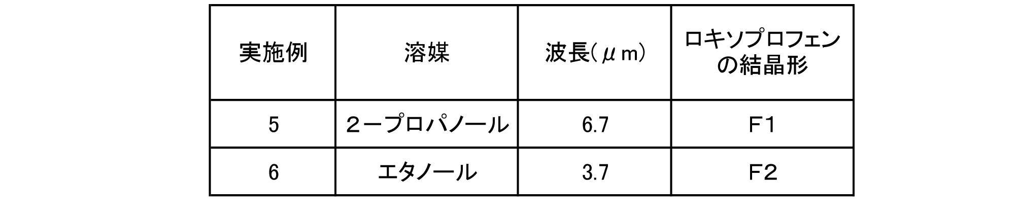
以上の実施例5,6から、ロキソプロフェンの2つの結晶形F1,F2のどちらの結晶形を析出させたいかによって、溶媒と赤外線のピーク波長との組合せを決定すればよいことがわかる。具体的には、結晶形F1のロキソプロフェンを析出させたい場合には、溶媒として2-プロパノールを用い、ピーク波長が6.7μmの赤外線を照射すればよい。結晶形F2のロキソプロフェンを析出させたい場合には、溶媒としてエタノールを用い、ピーク波長が3.7μmの赤外線を照射すればよい。
ロキソプロフェンの結晶形の安定度は、安定な順にF2,F1であり、F2が最安定形、F1が準安定形と考えられる。最安定形を析出させる場合には、溶解速度が速い溶媒を用いるのが好ましく、波長に関しては最安定形が吸収しにくい波長を選択するのが好ましい。以上のことから、ロキソプロフェンの最安定形のF2を選択的に析出させる場合、溶媒としては溶解速度が速いエタノールを選択し、波長としては比較的吸収しにくい3.7μmを選択する。準安定形を析出させる場合には、溶解速度が遅い溶媒を用いるのが好ましく、波長に関しては、準安定形が吸収しにくく他の結晶形が吸収しやすい波長を選択するのが好ましい。以上のことから、ロキソプロフェンの準安定形のF1を選択的に析出させる場合、溶媒としては溶解速度が遅い2-プロパノールを選択し、波長としては他の結晶形よりも吸収しにくい波長6.7μmを選択する。
[実施例7]
ジクロフェナク(製品コードD3748,東京化成工業)25mgをフラットシャーレ(φ32mm×16mm)に量り取り、混合溶媒(エタノール:2-プロパノール(IPA)=50:50(体積比))1mLを加え、80℃に調温したホットプレート上で1分間加温し、軽く撹拌しながら溶解させることにより試験サンプルを作製した。その試験サンプルに波長6.7μmを含む赤外線(ここでは波長6.7μmにピークを持つ赤外線)を放射することで溶媒を蒸発させ結晶を析出させた。析出した結晶について、XRD分析によって結晶形を同定したところ、結晶形はF1であった。
ジクロフェナク(製品コードD3748,東京化成工業)25mgをフラットシャーレ(φ32mm×16mm)に量り取り、混合溶媒(エタノール:2-プロパノール(IPA)=50:50(体積比))1mLを加え、80℃に調温したホットプレート上で1分間加温し、軽く撹拌しながら溶解させることにより試験サンプルを作製した。その試験サンプルに波長6.7μmを含む赤外線(ここでは波長6.7μmにピークを持つ赤外線)を放射することで溶媒を蒸発させ結晶を析出させた。析出した結晶について、XRD分析によって結晶形を同定したところ、結晶形はF1であった。
[実施例8]
溶媒として混合溶媒の代わりにエタノールを使用し、波長6.7μmを含む赤外線の代わりに波長3.7μmを含む赤外線(ここでは波長3.7にピークを持つ赤外線)を用いた以外は、実施例7と同様にして結晶を析出させた。析出した結晶について、XRD分析によって結晶形を同定したところ、結晶形はF2であった。
溶媒として混合溶媒の代わりにエタノールを使用し、波長6.7μmを含む赤外線の代わりに波長3.7μmを含む赤外線(ここでは波長3.7にピークを持つ赤外線)を用いた以外は、実施例7と同様にして結晶を析出させた。析出した結晶について、XRD分析によって結晶形を同定したところ、結晶形はF2であった。
実施例7,8の結果を表5にまとめた。

以上の実施例7,8から、ジクロフェナクの2つの結晶形F1,F2のどちらの結晶形を析出させたいかによって、溶媒と赤外線のピーク波長との組合せを決定すればよいことがわかる。具体的には、結晶形F1のジクロフェナクを析出させたい場合には、溶媒としてエタノール:IPA=50:50(体積比)を用い、ピーク波長が6.7μmの赤外線を照射すればよい。結晶形F2のジクロフェナクを析出させたい場合には、溶媒としてエタノールを用い、ピーク波長が3.7μmの赤外線を照射すればよい。
ジクロフェナクの結晶形の安定度は、安定な順にF2,F1であり、F2が最安定形、F1が準安定形と考えられる。最安定形を析出させる場合には、溶解速度が速い溶媒を用いるのが好ましく、波長に関しては最安定形が吸収しにくい波長を選択するのが好ましい。以上のことから、ジクロフェナクの最安定形のF2を選択的に析出させる場合、溶媒としては溶解速度が速いエタノールを選択し、波長としては比較的吸収しにくい3.7μmを選択する。準安定形を析出させる場合には、溶解速度が遅い溶媒を用いるのが好ましく、波長に関しては、準安定形が吸収しにくく他の結晶形が吸収しやすい波長を選択するのが好ましい。以上のことから、ジクロフェナクの準安定形のF1を選択的に析出させる場合、溶媒としては溶解速度が遅いエタノール:IPA=50:50(体積比)を選択し、波長としては他の結晶形よりも吸収しにくい波長6.7μmを選択する。
本発明は、例えば複数の結晶形を有する化合物の特定の結晶形を選択的に得るのに利用可能である。
1 精製装置、10 赤外線ヒーター、11 ヒーター本体、12 発熱体、13 保護部材、20 フラットシャーレ、22 溶液、30 構造体、31 第1導体層、32 金属電極、34 誘電体層、35 第2導体層、37 支持基板、38 放射面、70 ケーシング、W1 横幅、W2 縦幅、D1,D2 間隔。
Claims (7)
- 少なくとも1つの結晶形を持つ化合物を結晶化させる精製方法であって、
前記化合物を溶媒に溶解させた溶液から特定の結晶形が析出する特定の赤外線波長を目標波長に設定し、前記目標波長を含む赤外線を放出可能な赤外線放出装置を用いて、前記溶液に前記目標波長を含む赤外線を照射させながら前記溶媒を蒸発させて前記特定の結晶形を析出させる方法であり、
前記特定の赤外線波長を前記目標波長に設定するにあたり、前記結晶形の赤外線吸収スペクトルと前記溶媒に対する前記化合物の溶解速度とに基づいて設定する、
精製方法。 - 前記化合物は、複数の結晶形を持つものである、
請求項1に記載の精製方法。 - 前記特定の赤外線波長を前記目標波長に設定するにあたり、前記結晶形の安定度と前記結晶形の赤外線吸収スペクトルと前記溶媒に対する前記化合物の溶解速度とに基づいて設定する、
請求項1又は2に記載の精製方法。 - 前記赤外線放出装置は、板状の放射体と、熱源としての面状ヒーターとを有する、
請求項1~3のいずれか1項に記載の精製方法。 - 前記赤外線放出装置は、前記目標波長にピークを有する赤外線を放出可能である、
請求項1~4のいずれか1項に記載の精製方法。 - 前記赤外線放出装置は、外から内に向かって金属パターンと誘電体層と金属基板とがこの順に積層された構造体から前記目標波長にピークを有する赤外線を放出するものであり、前記金属パターンは、前記誘電体層状に同じ形状で同じサイズの金属電極が互いに等間隔に配列されたものであり、前記金属電極の幅に応じて放射する赤外線のピーク波長が変化する、
請求項5に記載の精製方法。 - 前記化合物は、フェブキソスタット、ロキソプロフェン又はジクロフェナクである、
請求項1~6のいずれか1項に記載の精製方法。
Priority Applications (4)
| Application Number | Priority Date | Filing Date | Title |
|---|---|---|---|
| CN202180023513.2A CN115315298B (zh) | 2020-07-13 | 2021-07-06 | 精制方法 |
| JP2022517273A JP7096957B2 (ja) | 2020-07-13 | 2021-07-06 | 精製方法 |
| EP21841440.7A EP4180104A1 (en) | 2020-07-13 | 2021-07-06 | Refining method |
| US18/147,229 US20230150957A1 (en) | 2020-07-13 | 2022-12-28 | Refining method |
Applications Claiming Priority (2)
| Application Number | Priority Date | Filing Date | Title |
|---|---|---|---|
| JP2020027266 | 2020-07-13 | ||
| JPPCT/JP2020/027266 | 2020-07-13 |
Related Child Applications (1)
| Application Number | Title | Priority Date | Filing Date |
|---|---|---|---|
| US18/147,229 Continuation US20230150957A1 (en) | 2020-07-13 | 2022-12-28 | Refining method |
Publications (1)
| Publication Number | Publication Date |
|---|---|
| WO2022014395A1 true WO2022014395A1 (ja) | 2022-01-20 |
Family
ID=79555315
Family Applications (3)
| Application Number | Title | Priority Date | Filing Date |
|---|---|---|---|
| PCT/JP2021/025388 WO2022014395A1 (ja) | 2020-07-13 | 2021-07-06 | 精製方法 |
| PCT/JP2021/025390 WO2022014397A1 (ja) | 2020-07-13 | 2021-07-06 | 精製方法 |
| PCT/JP2021/025389 WO2022014396A1 (ja) | 2020-07-13 | 2021-07-06 | 精製方法 |
Family Applications After (2)
| Application Number | Title | Priority Date | Filing Date |
|---|---|---|---|
| PCT/JP2021/025390 WO2022014397A1 (ja) | 2020-07-13 | 2021-07-06 | 精製方法 |
| PCT/JP2021/025389 WO2022014396A1 (ja) | 2020-07-13 | 2021-07-06 | 精製方法 |
Country Status (5)
| Country | Link |
|---|---|
| US (3) | US20230150958A1 (ja) |
| EP (3) | EP4180105A1 (ja) |
| JP (4) | JP7096956B2 (ja) |
| CN (3) | CN115315298B (ja) |
| WO (3) | WO2022014395A1 (ja) |
Families Citing this family (1)
| Publication number | Priority date | Publication date | Assignee | Title |
|---|---|---|---|---|
| KR102485717B1 (ko) * | 2017-09-01 | 2023-01-09 | 삼성전자주식회사 | 공기조화기 |
Citations (4)
| Publication number | Priority date | Publication date | Assignee | Title |
|---|---|---|---|---|
| JPH0142355B2 (ja) | 1982-04-19 | 1989-09-12 | Taiyo Sanso Co Ltd | |
| JP2004267114A (ja) * | 2003-03-10 | 2004-09-30 | Ishii Iron Works Co Ltd | 酒石酸塩の析出分離方法及びその方法を用いて得られた赤外線照射飲料 |
| JP2012529537A (ja) * | 2009-06-10 | 2012-11-22 | テバ ファーマシューティカル インダストリーズ リミティド | フェブキソスタットの結晶形 |
| WO2018034305A1 (ja) * | 2016-08-19 | 2018-02-22 | 日本碍子株式会社 | 有機化合物の精製方法 |
Family Cites Families (27)
| Publication number | Priority date | Publication date | Assignee | Title |
|---|---|---|---|---|
| GB2122602B (en) * | 1982-06-07 | 1985-06-05 | Hisamitsu Pharmaceutical Co | Novel 2 3-dihydro-indene derivatives |
| JPH0744154B2 (ja) * | 1987-12-16 | 1995-05-15 | 株式会社豊田中央研究所 | 光照射型低温mocvd方法および装置 |
| JP3805533B2 (ja) * | 1998-07-21 | 2006-08-02 | 東京瓦斯株式会社 | 同位体分離方法 |
| WO2001002075A1 (en) * | 1999-07-06 | 2001-01-11 | Myerson Allan S | Method for using laser light to control crystal form |
| RU2160795C1 (ru) * | 1999-07-07 | 2000-12-20 | Уральский государственный технический университет | Способ получения высокочистых веществ |
| JP2001247526A (ja) * | 2000-03-06 | 2001-09-11 | Toyobo Co Ltd | 近赤外線吸収化合組成物および近赤外線吸収フィルター |
| EP1172646A1 (en) * | 2000-07-13 | 2002-01-16 | Universiteit Leiden | Screening crystallisation conditions of organic compounds |
| CA2480003A1 (en) * | 2002-03-21 | 2003-10-30 | Berkshire Laboratories, Inc. | Methods for controlling crystal growth, crystallization, structures and phases in materials and systems |
| JP2003319800A (ja) * | 2002-05-07 | 2003-11-11 | Itochu Seito Kk | 砂糖の製造方法 |
| JP2004226277A (ja) * | 2003-01-23 | 2004-08-12 | Bios Ikagaku Kenkyusho:Kk | 生体物質および化学物質の光学的測定方法および光学的測定装置 |
| CN101277959A (zh) * | 2005-10-03 | 2008-10-01 | 马林克罗特公司 | 制备唑吡坦半酒石酸盐和酒石酸盐多晶型的方法 |
| CN100417750C (zh) * | 2006-05-23 | 2008-09-10 | 青岛大学 | 溶液法晶体快速生长装置 |
| EP1887004A1 (en) * | 2006-08-07 | 2008-02-13 | Palau Pharma, S.A. | Crystalline forms of (1R,2R)-7-Chloro-3-[2-(2,4-difluorophenyl)-2-hydroxy-1-methyl-3-(1H-1,2,4-triazol-1-yl)propyl]quinazolin-4(3H)-one |
| SI2114405T1 (sl) * | 2006-12-28 | 2015-06-30 | F. Hoffmann-La Roche Ag | Kokristalna oblika "a" metilparabena (4-(3-fluoro-5-trifluorometil-piridin-2-il)-piperazin-1-il)-(5-metan- sulfonil-2-((s)-2,2,2-trifluoro-1-metil-etoksi)-fenil)-metanona |
| WO2012009262A2 (en) * | 2010-07-12 | 2012-01-19 | Yung Shin Pharm. Ind. Co., Ltd. | Diclofenac salt of tramadol |
| CN102267957B (zh) * | 2011-08-24 | 2013-04-24 | 山东齐都药业有限公司 | 非布司他a晶型的制备方法 |
| JP2014189462A (ja) | 2013-03-27 | 2014-10-06 | Osaka Univ | 結晶製造方法、準安定形結晶、医薬の製造方法および医薬 |
| JP2014214299A (ja) * | 2013-04-30 | 2014-11-17 | 旭硝子株式会社 | 近赤外線吸収粒子、その製造方法、分散液およびその物品 |
| CA2926071C (en) * | 2013-10-08 | 2021-11-09 | Meiji Seika Pharma Co., Ltd. | Crystalline forms of diazabicyclooctane derivative and production process thereof |
| JP2017061582A (ja) * | 2014-02-07 | 2017-03-30 | 国立研究開発法人産業技術総合研究所 | 蛍光体微粒子の製造方法、蛍光体薄膜、波長変換膜、波長変換デバイス及び太陽電池 |
| WO2015140062A1 (de) * | 2014-03-19 | 2015-09-24 | Basf Se | Verfahren und vorrichtung zum abtrennen eines stoffes aus einer lösung |
| WO2016133170A1 (ja) * | 2015-02-20 | 2016-08-25 | 株式会社クラレ | イオン交換膜 |
| US20160289173A1 (en) * | 2015-04-02 | 2016-10-06 | Massachusetts Institute Of Technology | Devices and methods for crystallizing a compound |
| GB2548342B (en) * | 2016-03-10 | 2021-04-07 | Rotam Agrochem Int Co Ltd | A novel form of amicarbazone, a process for its preparation and use of the same |
| CN107216339B (zh) * | 2016-03-22 | 2021-05-04 | 中国科学院上海药物研究所 | 一种dppiv抑制剂马来酸盐的多晶型及其制备方法 |
| CN105753733B (zh) * | 2016-04-15 | 2019-06-18 | 苏州晶云药物科技股份有限公司 | Ahu377的晶型及其制备方法与用途 |
| CN110799264A (zh) * | 2017-07-05 | 2020-02-14 | 日本碍子株式会社 | 红外线处理装置 |
-
2021
- 2021-07-06 JP JP2022517272A patent/JP7096956B2/ja active Active
- 2021-07-06 JP JP2022517273A patent/JP7096957B2/ja active Active
- 2021-07-06 WO PCT/JP2021/025388 patent/WO2022014395A1/ja unknown
- 2021-07-06 WO PCT/JP2021/025390 patent/WO2022014397A1/ja unknown
- 2021-07-06 EP EP21843135.1A patent/EP4180105A1/en active Pending
- 2021-07-06 CN CN202180023513.2A patent/CN115315298B/zh active Active
- 2021-07-06 CN CN202180023519.XA patent/CN115315299A/zh active Pending
- 2021-07-06 EP EP21843513.9A patent/EP4180106A1/en active Pending
- 2021-07-06 WO PCT/JP2021/025389 patent/WO2022014396A1/ja unknown
- 2021-07-06 CN CN202180023504.3A patent/CN115315297A/zh active Pending
- 2021-07-06 JP JP2022517274A patent/JP7096958B2/ja active Active
- 2021-07-06 EP EP21841440.7A patent/EP4180104A1/en active Pending
-
2022
- 2022-06-20 JP JP2022098548A patent/JP2022125073A/ja active Pending
- 2022-12-28 US US18/147,251 patent/US20230150958A1/en active Pending
- 2022-12-28 US US18/147,198 patent/US20230167577A1/en active Pending
- 2022-12-28 US US18/147,229 patent/US20230150957A1/en active Pending
Patent Citations (4)
| Publication number | Priority date | Publication date | Assignee | Title |
|---|---|---|---|---|
| JPH0142355B2 (ja) | 1982-04-19 | 1989-09-12 | Taiyo Sanso Co Ltd | |
| JP2004267114A (ja) * | 2003-03-10 | 2004-09-30 | Ishii Iron Works Co Ltd | 酒石酸塩の析出分離方法及びその方法を用いて得られた赤外線照射飲料 |
| JP2012529537A (ja) * | 2009-06-10 | 2012-11-22 | テバ ファーマシューティカル インダストリーズ リミティド | フェブキソスタットの結晶形 |
| WO2018034305A1 (ja) * | 2016-08-19 | 2018-02-22 | 日本碍子株式会社 | 有機化合物の精製方法 |
Non-Patent Citations (3)
| Title |
|---|
| ACS CENT. SCI., vol. 5, 2019, pages 319 - 326 |
| JSME TED NEWSLETTER, no. 74, 10 July 2014 (2014-07-10) |
| JSME TED NEWSLETTER, no. 74, 2014, pages 2 - 6 |
Also Published As
| Publication number | Publication date |
|---|---|
| WO2022014396A1 (ja) | 2022-01-20 |
| JPWO2022014397A1 (ja) | 2022-01-20 |
| JPWO2022014396A1 (ja) | 2022-01-20 |
| EP4180106A1 (en) | 2023-05-17 |
| JPWO2022014395A1 (ja) | 2022-01-20 |
| CN115315299A (zh) | 2022-11-08 |
| EP4180104A1 (en) | 2023-05-17 |
| WO2022014397A1 (ja) | 2022-01-20 |
| CN115315297A (zh) | 2022-11-08 |
| EP4180105A1 (en) | 2023-05-17 |
| CN115315298B (zh) | 2023-09-15 |
| JP7096956B2 (ja) | 2022-07-06 |
| US20230167577A1 (en) | 2023-06-01 |
| JP7096957B2 (ja) | 2022-07-06 |
| US20230150958A1 (en) | 2023-05-18 |
| CN115315298A (zh) | 2022-11-08 |
| US20230150957A1 (en) | 2023-05-18 |
| JP2022125073A (ja) | 2022-08-26 |
| JP7096958B2 (ja) | 2022-07-06 |
Similar Documents
| Publication | Publication Date | Title |
|---|---|---|
| JP7242806B2 (ja) | 有機化合物の精製方法 | |
| CN1924079B (zh) | 线型沉积源 | |
| WO2022014395A1 (ja) | 精製方法 | |
| US20200122112A1 (en) | Infrared processing device | |
| US10822292B2 (en) | Method for producing reaction product | |
| Nickel et al. | Reversible switching of spiropyran molecules in direct contact with a Bi (111) single crystal surface | |
| Piqueras et al. | Growth of metal oxide nanostructures by thermal oxidation of metals under influence of external electric fields and electric current flow | |
| WO2022013919A1 (ja) | 精製方法 | |
| US20210045195A1 (en) | Infrared radiation device | |
| JP2004269987A (ja) | 金属ナノワイヤーの製造方法 | |
| WO2023062715A1 (ja) | 低アルコール飲料の製法 | |
| Borhade et al. | Synthesis, characterization and gas sensing performance of aluminosilicate azide cancrinite | |
| JP2009228120A (ja) | 成膜装置、及び成膜方法 | |
| US10245574B1 (en) | Microwave reactor vessel | |
| JPH05163572A (ja) | ダイヤモンド成膜装置 | |
| JP2013082566A (ja) | 酸化グラフェンシート分散体およびその製造方法 | |
| Chibante | Production, characterization and reactions of fullerenes | |
| Shen | A Novel nonlithographic method to fabricate nanoparticles and its application in crystallization of amorphous silicon thin films |
Legal Events
| Date | Code | Title | Description |
|---|---|---|---|
| 121 | Ep: the epo has been informed by wipo that ep was designated in this application |
Ref document number: 21841440 Country of ref document: EP Kind code of ref document: A1 |
|
| ENP | Entry into the national phase |
Ref document number: 2022517273 Country of ref document: JP Kind code of ref document: A |
|
| NENP | Non-entry into the national phase |
Ref country code: DE |
|
| ENP | Entry into the national phase |
Ref document number: 2021841440 Country of ref document: EP Effective date: 20230213 |