WO2021149494A1 - ワイヤハーネス - Google Patents
ワイヤハーネス Download PDFInfo
- Publication number
- WO2021149494A1 WO2021149494A1 PCT/JP2021/000260 JP2021000260W WO2021149494A1 WO 2021149494 A1 WO2021149494 A1 WO 2021149494A1 JP 2021000260 W JP2021000260 W JP 2021000260W WO 2021149494 A1 WO2021149494 A1 WO 2021149494A1
- Authority
- WO
- WIPO (PCT)
- Prior art keywords
- connector
- shield member
- wire
- drain
- wire harness
- Prior art date
- Legal status (The legal status is an assumption and is not a legal conclusion. Google has not performed a legal analysis and makes no representation as to the accuracy of the status listed.)
- Ceased
Links
Images


Classifications
-
- H—ELECTRICITY
- H01—ELECTRIC ELEMENTS
- H01B—CABLES; CONDUCTORS; INSULATORS; SELECTION OF MATERIALS FOR THEIR CONDUCTIVE, INSULATING OR DIELECTRIC PROPERTIES
- H01B7/00—Insulated conductors or cables characterised by their form
- H01B7/0045—Cable-harnesses
-
- H—ELECTRICITY
- H01—ELECTRIC ELEMENTS
- H01R—ELECTRICALLY-CONDUCTIVE CONNECTIONS; STRUCTURAL ASSOCIATIONS OF A PLURALITY OF MUTUALLY-INSULATED ELECTRICAL CONNECTING ELEMENTS; COUPLING DEVICES; CURRENT COLLECTORS
- H01R13/00—Details of coupling devices of the kinds covered by groups H01R12/70 or H01R24/00 - H01R33/00
- H01R13/648—Protective earth or shield arrangements on coupling devices, e.g. anti-static shielding
- H01R13/658—High frequency shielding arrangements, e.g. against EMI [Electro-Magnetic Interference] or EMP [Electro-Magnetic Pulse]
- H01R13/6591—Specific features or arrangements of connection of shield to conductive members
-
- G—PHYSICS
- G01—MEASURING; TESTING
- G01R—MEASURING ELECTRIC VARIABLES; MEASURING MAGNETIC VARIABLES
- G01R31/00—Arrangements for testing electric properties; Arrangements for locating electric faults; Arrangements for electrical testing characterised by what is being tested not provided for elsewhere
- G01R31/50—Testing of electric apparatus, lines, cables or components for short-circuits, continuity, leakage current or incorrect line connections
- G01R31/54—Testing for continuity
-
- H—ELECTRICITY
- H01—ELECTRIC ELEMENTS
- H01B—CABLES; CONDUCTORS; INSULATORS; SELECTION OF MATERIALS FOR THEIR CONDUCTIVE, INSULATING OR DIELECTRIC PROPERTIES
- H01B7/00—Insulated conductors or cables characterised by their form
- H01B7/17—Protection against damage caused by external factors, e.g. sheaths or armouring
- H01B7/18—Protection against damage caused by wear, mechanical force or pressure; Sheaths; Armouring
- H01B7/20—Metal tubes, e.g. lead sheaths
-
- H—ELECTRICITY
- H01—ELECTRIC ELEMENTS
- H01B—CABLES; CONDUCTORS; INSULATORS; SELECTION OF MATERIALS FOR THEIR CONDUCTIVE, INSULATING OR DIELECTRIC PROPERTIES
- H01B7/00—Insulated conductors or cables characterised by their form
- H01B7/17—Protection against damage caused by external factors, e.g. sheaths or armouring
- H01B7/18—Protection against damage caused by wear, mechanical force or pressure; Sheaths; Armouring
- H01B7/22—Metal wires or tapes, e.g. made of steel
- H01B7/228—Metal braid
-
- H—ELECTRICITY
- H01—ELECTRIC ELEMENTS
- H01R—ELECTRICALLY-CONDUCTIVE CONNECTIONS; STRUCTURAL ASSOCIATIONS OF A PLURALITY OF MUTUALLY-INSULATED ELECTRICAL CONNECTING ELEMENTS; COUPLING DEVICES; CURRENT COLLECTORS
- H01R13/00—Details of coupling devices of the kinds covered by groups H01R12/70 or H01R24/00 - H01R33/00
- H01R13/46—Bases; Cases
-
- H—ELECTRICITY
- H01—ELECTRIC ELEMENTS
- H01R—ELECTRICALLY-CONDUCTIVE CONNECTIONS; STRUCTURAL ASSOCIATIONS OF A PLURALITY OF MUTUALLY-INSULATED ELECTRICAL CONNECTING ELEMENTS; COUPLING DEVICES; CURRENT COLLECTORS
- H01R31/00—Coupling parts supported only by co-operation with counterpart
- H01R31/08—Short-circuiting members for bridging contacts in a counterpart
-
- B—PERFORMING OPERATIONS; TRANSPORTING
- B60—VEHICLES IN GENERAL
- B60R—VEHICLES, VEHICLE FITTINGS, OR VEHICLE PARTS, NOT OTHERWISE PROVIDED FOR
- B60R16/00—Electric or fluid circuits specially adapted for vehicles and not otherwise provided for; Arrangement of elements of electric or fluid circuits specially adapted for vehicles and not otherwise provided for
- B60R16/02—Electric or fluid circuits specially adapted for vehicles and not otherwise provided for; Arrangement of elements of electric or fluid circuits specially adapted for vehicles and not otherwise provided for electric constitutive elements
- B60R16/0207—Wire harnesses
-
- H—ELECTRICITY
- H01—ELECTRIC ELEMENTS
- H01R—ELECTRICALLY-CONDUCTIVE CONNECTIONS; STRUCTURAL ASSOCIATIONS OF A PLURALITY OF MUTUALLY-INSULATED ELECTRICAL CONNECTING ELEMENTS; COUPLING DEVICES; CURRENT COLLECTORS
- H01R2201/00—Connectors or connections adapted for particular applications
- H01R2201/20—Connectors or connections adapted for particular applications for testing or measuring purposes
-
- H—ELECTRICITY
- H01—ELECTRIC ELEMENTS
- H01R—ELECTRICALLY-CONDUCTIVE CONNECTIONS; STRUCTURAL ASSOCIATIONS OF A PLURALITY OF MUTUALLY-INSULATED ELECTRICAL CONNECTING ELEMENTS; COUPLING DEVICES; CURRENT COLLECTORS
- H01R2201/00—Connectors or connections adapted for particular applications
- H01R2201/26—Connectors or connections adapted for particular applications for vehicles
Definitions
- This disclosure relates to a wire harness.
- the electric wire is covered with a shield member made of a conductor (the conductive layer in Patent Document 1), and the drain wire electrically conductive to the shield member is an end portion of the wire harness. It is inserted into the cavity of the connector provided in.
- the drain wire inserted into the cavity of the connector is electrically connected to the terminal provided in the cavity, and the terminal is connected to the terminal of the mating connector to which the connector of the wire harness is connected.
- the drain wire since the drain wire is connected to the connector, it is possible to inspect the continuity of the shield member including the drain wire via the connector.
- the wire harness of the present disclosure includes an electric wire, a connector connected to one end of the electric wire, a tubular shield member covering the electric wire, and the connector in the shield member which is electrically conductive to the shield member.
- a drain wire drawn from a side end is provided, and the drain wire is inserted into an empty cavity of the connector.
- the wire harness of the present disclosure includes a first electric wire, a tubular first shield member covering the first electric wire, and a pair of drain wires drawn from both ends in the length direction of the first shield member.
- a first wire harness provided with a first connector provided at one end of the first electric wire, a second electric wire, a tubular second shield member covering the second electric wire, and the first wire.
- a second wire harness including a pair of drain wires drawn from both ends in the length direction of the two shield members and a second connector provided at one end of the second electric wire, and the first shield member.
- the drain wire drawn from the end opposite to the first connector in the second shield member is electrically connected to the drain wire drawn from the end opposite to the second connector in the second shield member.
- the drain wire provided with the connecting member and drawn from the end of the first shield member on the first connector side is grounded, and the drain drawn from the end of the second shield member on the second connector side is grounded. The wire is inserted into the empty cavity of the second connector.
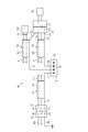
- FIG. 1 is a schematic configuration diagram of a wire harness according to an embodiment.
- FIG. 2 is an explanatory diagram for explaining a mode of continuity inspection of the shield member in the same embodiment.
- FIG. 3 is a schematic configuration diagram of a wire harness in a modified example.
- FIG. 4 is a schematic view of the joint connector.
- the wire harness of the present disclosure is [1] An electric wire, a connector connected to one end of the electric wire, a tubular shield member covering the electric wire, and an end portion of the shield member on the connector side that is electrically conductive to the shield member.
- a drain wire drawn from the connector is provided, and the drain wire is inserted into an empty cavity of the connector.
- the empty cavity of the connector is a cavity in which the corresponding terminal does not exist in the mating connector connected to the connector.
- the wire harness of the present disclosure is [2] A first electric wire, a tubular first shield member covering the first electric wire, a pair of drain wires drawn from both ends in the length direction of the first shield member, and the first electric wire.
- the length of the first wire harness provided with the first connector provided at one end of the above, the second electric wire, the tubular second shield member covering the second electric wire, and the second shield member.
- a second wire harness including a pair of drain wires drawn from both ends in the direction and a second connector provided at one end of the second electric wire, and the pair of drain wires of the first wire harness.
- the first shield member one of the drain wires drawn from the end opposite to the first connector and the pair of drain wires of the second wire harness, the first of the second shield members.
- the first shield member of the pair of drain wires of the first wire harness includes a connecting member for electrically connecting one drain wire drawn from an end opposite to the connector.
- the other drain wire drawn from the end on the first connector side is grounded, and is drawn from the end on the second connector side of the second shield member of the pair of drain wires of the second wire harness.
- the other drain wire is inserted into the empty cavity of the second connector.
- the empty cavity of the second connector is a cavity in which the corresponding terminal does not exist in the mating connector connected to the second connector.
- the other drain wire drawn from the end on the first connector side of the first shield member is connected to the first connector. Is preferable.
- the connecting member is a splice part.
- a third electric wire a tubular third shield member covering the third electric wire, a pair of drain wires drawn from both ends in the length direction of the third shield member, and the third electric wire.
- a third wire harness including a third connector provided at one end of the third wire harness is provided, and the pair of drain wires of the third wire harness on the side opposite to the third connector in the third shield member.
- One of the drain wires drawn out from the end portion is electrically connected to the first shield member and the second shield member via the connecting member, and is said to be among the pair of drain wires of the third wire harness. It is preferable that the other drain wire drawn from the end portion of the third shield member on the third connector side is inserted into an empty cavity different from the empty cavity of the second connector.
- the wire harness W for a vehicle includes a first wire harness 10 and a second wire harness 20. Further, the wire harness W includes a connecting member 30 for electrically connecting the drain wire 14 of the first wire harness 10 and the drain wire 24 of the second wire harness 20.
- the first wire harness 10 is pulled out from a plurality of first electric wires 11, a tubular first shield member 12 that collectively covers the plurality of first electric wires 11, and both ends in the length direction of the first shield member 12.
- the pair of drain wires 13 and 14 and the first connector 15 provided at one end of the first electric wire 11 are provided.
- a tubular member obtained by rolling a metal foil into a tubular shape, a metal braid formed by knitting a plurality of metal strands into a tubular shape, or the like can be used.
- the outer circumference of the first shield member 12 is covered with a tubular exterior member (not shown).
- the drain wires 13 and 14 are electrically connected to the first shield member 12.
- each first electric wire 11 is inserted into the first connector 15 and is connected to the terminal 16 included in the first connector 15. Further, the other end of each first electric wire 11 is connected to a device (not shown) mounted on the vehicle.
- the first connector 15 is a so-called wire-to-wire type connector.
- the terminal 16 of the first connector 15 is connected to the terminal 42 of the mating connector 41 connected to the first connector 15.
- the terminal 42 of the mating connector 41 is connected to an electric wire 44 connected to a device (not shown) mounted on the vehicle.
- One of the pair of drain wires 13 and 14 is inserted into the first connector 15 and is connected to the terminal 17 included in the first connector 15.
- the terminal 17 of the first connector 15 is connected to the terminal 43 of the mating connector 41 connected to the first connector 15.
- the electric wire 45 connected to the terminal 43 of the mating connector 41 is grounded to the vehicle body, the ground terminal, or the like.
- the second wire harness 20 is pulled out from a plurality of second electric wires 21, a tubular second shield member 22 that collectively covers the plurality of second electric wires 21, and both ends of the second shield member 22 in the length direction.
- the pair of drain wires 23 and 24 and the second connector 25 provided at one end of the second electric wire 21 are provided.
- a tubular member obtained by rolling a metal foil into a tubular shape, a metal braid formed by knitting a plurality of metal strands into a tubular shape, or the like can be used.
- the outer circumference of the second shield member 22 is covered with a tubular exterior member (not shown).
- the drain wires 23 and 24 are electrically connected to the second shield member 22.
- each second electric wire 21 is inserted into the second connector 25 and is connected to the terminal 26 included in the second connector 25. Further, the other end of each second electric wire 21 is connected to a device (not shown) mounted on the vehicle.
- the second connector 25 is a so-called wire-to-wire type connector.
- the terminal 26 of the second connector 25 is connected to the terminal 47 of the mating connector 46 connected to the second connector 25.
- the terminal 47 of the mating connector 46 is connected to the electric wire 48 connected to the device D1 mounted on the vehicle.
- One of the pair of drain wires 23 and 24, the drain wire 23, is inserted into the empty cavity 27 of the second connector 25.
- the mating connector 46 connected to the second connector 25 is not provided with a terminal corresponding to the empty cavity 27 of the second connector 25. Further, the empty cavity 27 of the present embodiment is not provided with a terminal.
- the connecting member 30 is a so-called splice part, and includes a metal terminal 32 in the housing 31.
- the drain wire 14 of the first shield member 12 and the drain wire 24 of the second shield member 22 are inserted into the housing 31 and connected to the metal terminal 32.
- the drain wires 14 and 24 are electrically connected to each other via the metal terminals 32.
- FIG. 4 shows an example of a configuration in which the joint connector 60 is used instead of the connecting member 30 of the above embodiment.
- the housing 61 of the joint connector 60 is composed of at least two components, a connector housing 62 and a housing 63 with terminals.
- the housing 63 with terminals is configured to be detachable from the connector housing 62.
- the connector housing 62 has a plurality of cavities, and the drain wire 14 of the first shield member 12 and the drain wire 24 of the second shield member 22 are inserted into each of the cavities 62a and 62b of the plurality of cavities.
- the housing 63 with terminals includes a metal terminal 64 that integrally has a first terminal portion 64a and a second terminal portion 64b.
- the terminals 14a provided at the tip of the drain wire 14 and arranged in the cavity 62a are connected to the first terminal portion 64a of the metal terminal 64.
- the terminals 24a provided at the tip of the drain wire 24 and arranged in the cavity 62b are connected to the second terminal portion 64b of the metal terminal 64. .. That is, in this state, the drain wires 14 and 24 are electrically connected to each other via the metal terminals 64 of the housing 63 with terminals.
- the connection state of the terminals 14a and 24a by the metal terminals 64 is released, and the drain wires 14 and 24 are not electrically connected to each other.
- the connecting member 30 made of splice parts as in the present embodiment, which is different from the joint connector 60 as described above, is provided in the housing 31 accommodating the metal terminals 32 conducting the drain wires 14 and 24. , Cavities 31a and 31b into which the drain lines 14 and 24 are inserted are formed. Therefore, as compared with the joint connector 60, it is advantageous in simplifying and downsizing the configuration of the connecting member 30.
- FIG. 2 shows a mode of continuity inspection of the first shield member 12 and the second shield member 22.
- a galvanometer A having a first terminal A1 and a second terminal A2 is used for the continuity inspection of the first shield member 12 and the second shield member 22.
- the first connector 15 is not connected to the mating connector 41.
- the second connector 25 is not connected to the mating connector 46.
- the first terminal A1 connected to the galvanometer A is inserted into the cavity of the first connector 15 accommodating the terminal 17 connected to the drain wire 13 of the first shield member 12, and the first terminal A1 is inserted into the terminal. Contact with 17.
- the second terminal A2 connected to the galvanometer A is inserted into the empty cavity 27 of the second connector 25 accommodating the drain wire 23 of the second shield member 22, and the second terminal A2 comes into contact with the drain wire 23. Let me. Thereby, it is possible to inspect whether or not the current properly flows through the circuit including the first shield member 12 and the second shield member 22 by the galvanometer A.
- the drain wire 23 drawn from the end of the second shield member 22 on the second connector 25 side is inserted into the empty cavity 27 of the second connector 25. According to this configuration, since the drain wire 23 electrically conductive to the second shield member 22 is inserted into the empty cavity 27 of the second connector, the first shield member 12 and the first shield member 12 and the second shield member 12 via the second connector are inserted. 2 It is possible to inspect the continuity of the shield member 22.
- the empty cavity 27 of the second connector is a cavity in which the corresponding terminal does not exist in the mating connector connected to the second connector.
- the connecting member 30 that connects the first shield member 12 and the second shield member 22 is used as a splice part.
- the splice parts are advantageous in miniaturization as compared with the joint connector 60, it is difficult to bring the terminals of the galvanometer into contact with the drain wires 14 and 24 in the housing 31.
- the drain wire 23 of the second shield member 22 is inserted into the empty cavity 27 of the second connector 25 as in the present embodiment, even if the connecting member 30 is a splice part unsuitable for continuity inspection. , The continuity inspection of the first shield member 12 and the second shield member 22 can be performed.
- This embodiment can be implemented by changing as follows.
- the present embodiment and the following modified examples can be implemented in combination with each other within a technically consistent range.
- the configuration may be changed to the wire harness W1 shown in FIG.
- the same components as those in the above embodiment are designated by the same reference numerals as those in the above embodiment, and detailed description thereof will be omitted.
- the vehicle wire harness W1 shown in FIG. 3 includes a first wire harness 10, a second wire harness 20, and a third wire harness 50. Further, the wire harness W is a connecting member 30 for electrically connecting the drain wire 14 of the first wire harness 10, the drain wire 24 of the second wire harness 20, and the drain wire 54 of the third wire harness 50. It has.
- the first wire harness 10 has the same configuration as that of the above embodiment.
- the second wire harness 20 has substantially the same configuration as that of the above embodiment.
- the second connector 25 of the second wire harness 20 has at least two empty cavities 27 and 28.
- the mating connector 46 connected to the second connector 25 is not provided with terminals corresponding to the empty cavities 27 and 28 of the second connector 25, and the terminals are also provided in the empty cavities 27 and 28 of the second connector 25. Is not provided.
- the third wire harness 50 is pulled out from a plurality of third electric wires 51, a tubular third shield member 52 that collectively covers the plurality of third electric wires 51, and both ends of the third shield member 52 in the length direction. It includes a pair of drain wires 53 and 54, and a third connector 55 provided at one end of the third electric wire 51.
- a tubular member obtained by rolling a metal foil into a tubular shape, a metal braid formed by knitting a plurality of metal strands into a tubular shape, or the like can be used.
- the outer circumference of the third shield member 52 is covered with a tubular exterior member (not shown).
- the drain wires 53 and 54 are electrically connected to the third shield member 52.
- each third electric wire 51 is connected to the device D2 mounted on the vehicle via the third connector 55.
- the third connector 55 is a connector connected to the connector connection portion of the device D2, and is not provided with an empty cavity as provided in the second connector 25.
- One drain wire 53 in the third wire harness 50 is inserted into the empty cavity 28 of the second connector 25. That is, the second connector 25 has an empty cavity 27 into which the drain wire 23 of its own system is inserted, and an empty cavity 28 into which the drain wire 53 of the third wire harness 50 of another system is inserted.
- the third shield member 52 and the second shield member 22 are arranged at positions close to each other.
- the drain wire 14 of the first shield member 12, the drain wire 24 of the second shield member 22, and the drain wire 54 of the third shield member 52 are inserted into the housing 31 of the connecting member 30. , Is connected to the metal terminal 32 in the housing 31. As a result, the drain wires 14, 24, and 54 are electrically connected to each other via the metal terminals 32.
- the continuity inspection of the first shield member 12, the second shield member 22, and the third shield member 52 in the wire harness W1 will be described.
- a galvanometer A (see FIG. 2) similar to the above embodiment is used.
- the first connector 15 is not connected to the mating connector 41, and the second connector 25 is not connected to the mating connector 46.
- the first terminal A1 connected to the galvanometer A is inserted into the cavity of the first connector 15 accommodating the terminal 17 connected to the drain wire 13 of the first shield member 12, and the first terminal A1 is inserted into the terminal. Contact with 17.
- the second terminal A2 connected to the galvanometer A is inserted into the empty cavity 27 of the second connector 25 accommodating the drain wire 23 of the second shield member 22, and the second terminal A2 comes into contact with the drain wire 23. Let me. Thereby, it is possible to inspect whether or not the current properly flows through the circuit including the first shield member 12 and the second shield member 22 by the galvanometer A.
- the first terminal A1 connected to the galvanometer A is inserted into the cavity of the first connector 15 accommodating the terminal 17 connected to the drain wire 13 of the first shield member 12, and the first terminal A1 is inserted into the terminal. Contact with 17.
- the second terminal A2 connected to the galvanometer A is inserted into the empty cavity 28 of the second connector 25 accommodating the drain wire 53 of the third shield member 52, and the second terminal A2 comes into contact with the drain wire 53. Let me. Thereby, it is possible to inspect whether or not the current properly flows through the circuit including the first shield member 12 and the third shield member 52 by the galvanometer A.
- the drain wire 53 drawn from the end of the third shield member 52 on the third connector 55 side is different from the empty cavity 27 into which the drain wire 23 of the second shield member 22 is inserted. It is inserted into the empty cavity 28 of the second connector 25. As a result, even when an empty cavity is not set in the third connector 55 of the third wire harness 50, it is possible to inspect the continuity of the third shield member 52 via the second connector 25.
- the wire harness W of the above embodiment may include a terminal attached to the tip of the drain wire 23 and arranged in the empty cavity 27.
- the second terminal A2 of the galvanometer A can be easily conducted to the drain line 23.
- the wire harness W1 having the configuration shown in FIG. 3 may include terminals attached to the tips of the drain wires 23 and 53 and arranged in the empty cavities 27 and 28, respectively.
- the connecting member 30 is a splice part, but the present invention is not limited to this, and a joint connector 60 may be used instead of the connecting member 30.
- the wire harness W includes a plurality of wire harnesses (first wire harness 10 and second wire harness 20), but in addition to this, for example, the wire harness W includes only the second wire harness 20. It is also applicable to. In this case, the drain wire 24 of the second shield member 22 is grounded.
- the empty cavity 27 of the second connector 25 may be a gangway or a through hole penetrating the second connector 25.
- the second connector 25 may have a connecting end face that faces, contacts, or contacts the mating connector 46.
- the second terminal A2 of the galvanometer A may be accessible to the drain line 23 in the empty cavity 27 from the connection end face of the second connector 25.
Landscapes
- Physics & Mathematics (AREA)
- General Physics & Mathematics (AREA)
- Details Of Connecting Devices For Male And Female Coupling (AREA)
- Testing Of Short-Circuits, Discontinuities, Leakage, Or Incorrect Line Connections (AREA)
Priority Applications (2)
| Application Number | Priority Date | Filing Date | Title |
|---|---|---|---|
| CN202180008035.8A CN114930179B (zh) | 2020-01-20 | 2021-01-07 | 线束 |
| US17/792,242 US12080447B2 (en) | 2020-01-20 | 2021-01-07 | Wire harness including connector having vacant cavity |
Applications Claiming Priority (2)
| Application Number | Priority Date | Filing Date | Title |
|---|---|---|---|
| JP2020006542A JP7371505B2 (ja) | 2020-01-20 | 2020-01-20 | ワイヤハーネス |
| JP2020-006542 | 2020-01-20 |
Publications (1)
| Publication Number | Publication Date |
|---|---|
| WO2021149494A1 true WO2021149494A1 (ja) | 2021-07-29 |
Family
ID=76992576
Family Applications (1)
| Application Number | Title | Priority Date | Filing Date |
|---|---|---|---|
| PCT/JP2021/000260 Ceased WO2021149494A1 (ja) | 2020-01-20 | 2021-01-07 | ワイヤハーネス |
Country Status (4)
| Country | Link |
|---|---|
| US (1) | US12080447B2 (https=) |
| JP (1) | JP7371505B2 (https=) |
| CN (1) | CN114930179B (https=) |
| WO (1) | WO2021149494A1 (https=) |
Cited By (1)
| Publication number | Priority date | Publication date | Assignee | Title |
|---|---|---|---|---|
| US20220123542A1 (en) * | 2020-10-20 | 2022-04-21 | Guan Che Ting | Electrical Connection Monitoring Using Cable Shielding |
Families Citing this family (1)
| Publication number | Priority date | Publication date | Assignee | Title |
|---|---|---|---|---|
| JP7371505B2 (ja) * | 2020-01-20 | 2023-10-31 | 住友電装株式会社 | ワイヤハーネス |
Citations (5)
| Publication number | Priority date | Publication date | Assignee | Title |
|---|---|---|---|---|
| JPH04335170A (ja) * | 1991-05-09 | 1992-11-24 | Fujikura Ltd | ワイヤハーネスの検査方法および装置 |
| JPH087944A (ja) * | 1994-06-20 | 1996-01-12 | Yazaki Corp | シールド電線の端部処理用キャップ並びに該キャップを使用したワイヤハーネス並びに導通検査方法 |
| JP2010243206A (ja) * | 2009-04-01 | 2010-10-28 | Mitsubishi Electric Corp | ワイヤーハーネス導通検査装置 |
| JP2016112625A (ja) * | 2014-12-11 | 2016-06-23 | 株式会社ダイヘン | ロボット制御装置 |
| KR20160073149A (ko) * | 2014-12-16 | 2016-06-24 | 주식회사 유라코퍼레이션 | 검사장치 |
Family Cites Families (64)
| Publication number | Priority date | Publication date | Assignee | Title |
|---|---|---|---|---|
| US4662067A (en) * | 1986-04-07 | 1987-05-05 | Honeywell Information Systems Inc. | Apparatus and method for providing orientation of a coax cable having a ground termination bar |
| US5281150A (en) * | 1993-01-05 | 1994-01-25 | International Business Machines Corporation | Method and apparatus for connecting cable to the surface of printed circuit boards or the like |
| WO1995013621A1 (en) * | 1993-11-12 | 1995-05-18 | Alcoa Fujikura Ltd. | Short circuit protected splice connector |
| JP2929917B2 (ja) * | 1993-11-22 | 1999-08-03 | 住友電装株式会社 | ワイヤハーネスの防水構造 |
| US5470253A (en) * | 1994-10-03 | 1995-11-28 | Caterpillar Inc. | Engine wiring system |
| JPH08223735A (ja) * | 1995-02-15 | 1996-08-30 | Sumitomo Wiring Syst Ltd | シールド線の端部処理方法 |
| JPH08336219A (ja) * | 1995-06-07 | 1996-12-17 | Sumitomo Wiring Syst Ltd | シールド線の端末処理方法 |
| US5971799A (en) * | 1997-04-26 | 1999-10-26 | Swade; George | Y-shaped harness for the interconnection between a vehicle radio, a vehicle harness and add-on electronic device |
| JPH1187008A (ja) | 1997-09-11 | 1999-03-30 | Harness Sogo Gijutsu Kenkyusho:Kk | ワイヤハーネス及びその短絡及び連結状態検出装置 |
| JP3346463B2 (ja) * | 1998-02-06 | 2002-11-18 | 矢崎総業株式会社 | 車両用電源線及び車両用電源線の異常検出装置 |
| US6153975A (en) * | 1999-01-19 | 2000-11-28 | The Louis Berkman Company | Day light harness adaptor |
| JP2000268893A (ja) * | 1999-03-15 | 2000-09-29 | Sumitomo Wiring Syst Ltd | 複数のシールド線のアース接続構造 |
| JP2001077986A (ja) * | 1999-09-03 | 2001-03-23 | Sharp Corp | 原稿端検知装置、原稿読取り装置、およびファクシミリ装置 |
| US20020023771A1 (en) * | 1999-12-20 | 2002-02-28 | Gerencir Richard L. | Problem solver connectors |
| JP3617808B2 (ja) * | 2000-08-08 | 2005-02-09 | 本田技研工業株式会社 | ワイヤハーネス構造 |
| DE60121681T2 (de) * | 2000-08-02 | 2007-08-02 | Honda Giken Kogyo K.K. | Kabelbaumstruktur |
| JP2002084624A (ja) * | 2000-09-05 | 2002-03-22 | Sumitomo Wiring Syst Ltd | 高電圧用電気接続箱 |
| US6595789B2 (en) * | 2000-10-20 | 2003-07-22 | Autonetworks Technologies, Ltd. | Electronic unit, shield cable connecting structure, connecting method, wires waterproof-connecting structure, and method |
| US6672900B2 (en) * | 2000-10-23 | 2004-01-06 | Robert Bosch Corporation | Universal aftermarket connector |
| JP4914539B2 (ja) * | 2001-05-18 | 2012-04-11 | 矢崎総業株式会社 | シールドハーネスの組立方法 |
| JP2003223952A (ja) * | 2002-01-29 | 2003-08-08 | Sumitomo Wiring Syst Ltd | 合体式コネクタにおける電線保持構造 |
| US7083472B2 (en) * | 2004-06-10 | 2006-08-01 | Commscope Solutions Properties, Llc | Shielded jack assemblies and methods for forming a cable termination |
| US7059889B1 (en) * | 2005-10-12 | 2006-06-13 | Lear Corporation | Splice block for interconnecting electrical conductors |
| WO2007049724A1 (ja) * | 2005-10-27 | 2007-05-03 | Mitsubishi Cable Industries, Ltd. | 接続部材及び接続部材を用いたハーネス接続体 |
| JP5188713B2 (ja) * | 2006-02-02 | 2013-04-24 | 株式会社オートネットワーク技術研究所 | ドレン線止水構造を備えたシールド線およびドレン線止水方法 |
| EP1835295A1 (en) * | 2006-03-17 | 2007-09-19 | 3M Innovative Properties Company | Test connector, kit and method for distinguishing a group of wires from other wires of a multi-wire cable |
| JP2008108699A (ja) * | 2006-08-15 | 2008-05-08 | Auto Network Gijutsu Kenkyusho:Kk | シールド線のアース処理構造およびアース処理方法 |
| JP5181967B2 (ja) * | 2008-09-19 | 2013-04-10 | 住友電装株式会社 | ワイヤハーネス |
| JP2011014391A (ja) * | 2009-07-02 | 2011-01-20 | Yazaki Corp | 金属箔巻きシールド電線 |
| JP5494236B2 (ja) * | 2010-05-28 | 2014-05-14 | 株式会社オートネットワーク技術研究所 | アース接続装置およびそれを用いたワイヤハーネス |
| JP4961490B2 (ja) * | 2010-07-06 | 2012-06-27 | 日本航空電子工業株式会社 | コネクタ |
| US8376759B2 (en) * | 2010-09-20 | 2013-02-19 | Tyco Electronics Corporation | Connectors for E-textiles |
| US20130032395A1 (en) * | 2011-08-04 | 2013-02-07 | Delphi Technologies, Inc. | Wire connector assembly including splice elements for fluid environments and methods of making same |
| JP2013058330A (ja) * | 2011-09-07 | 2013-03-28 | Sumitomo Wiring Syst Ltd | シールド線のコネクタ接続端末処理構造部及びシールド線のコネクタ接続端末処理構造部の製造方法 |
| DE102011117085A1 (de) * | 2011-10-27 | 2013-05-02 | Md Elektronik Gmbh | Bordnetzkomponente für ein Datenübertragungssystem in einem Kraftfahrzeug |
| US9147955B2 (en) * | 2011-11-02 | 2015-09-29 | Ppc Broadband, Inc. | Continuity providing port |
| US20140238741A1 (en) * | 2012-03-19 | 2014-08-28 | Delphi Technologies, Inc. | Hermetically sealed wire connector assembly and method of making same |
| US20140209345A1 (en) * | 2013-01-25 | 2014-07-31 | Curtiss-Wright Flow Control Corporation | Power Connector for an Electrical Motor |
| US8992251B2 (en) * | 2013-03-19 | 2015-03-31 | Delphi Technologies, Inc. | Electrical splice assembly |
| US9142907B2 (en) * | 2013-12-10 | 2015-09-22 | Delphi Technologies, Inc. | Electrical connection system |
| JP2016048615A (ja) * | 2014-08-27 | 2016-04-07 | 住友電装株式会社 | ワイヤーハーネス |
| JP2016062816A (ja) * | 2014-09-19 | 2016-04-25 | 矢崎総業株式会社 | ワイヤハーネス及びワイヤハーネス製造方法 |
| JP6315341B2 (ja) * | 2014-12-15 | 2018-04-25 | 株式会社オートネットワーク技術研究所 | 車載ネットワークにおける幹線構造、及び車載ネットワーク用コネクタ |
| JP2016149249A (ja) * | 2015-02-12 | 2016-08-18 | 株式会社オートネットワーク技術研究所 | 外装ワイヤーハーネス |
| JP6204406B2 (ja) * | 2015-05-15 | 2017-09-27 | 矢崎総業株式会社 | シールド電線及びこれを用いたワイヤハーネス |
| WO2016191662A1 (en) * | 2015-05-27 | 2016-12-01 | Intelligent Technologies International, Inc. | Vehicle wire harness |
| JP2017021915A (ja) * | 2015-07-08 | 2017-01-26 | 日立金属株式会社 | コネクタ付きケーブル |
| JP6376078B2 (ja) * | 2015-08-24 | 2018-08-22 | 株式会社オートネットワーク技術研究所 | 筒状導電性編組及び電磁シールド付配線モジュール |
| EP3142127B1 (de) * | 2015-09-11 | 2017-08-30 | MD Elektronik GmbH | Elektrisches kabel mit beilauflitze |
| JP6353858B2 (ja) * | 2016-02-22 | 2018-07-04 | 矢崎総業株式会社 | ワイヤハーネス構造 |
| US10072362B2 (en) * | 2016-06-27 | 2018-09-11 | Pascale Industries, Inc. | Method for making a polymer-sheathed multi-filamentary strand |
| JP6673071B2 (ja) * | 2016-07-19 | 2020-03-25 | 株式会社オートネットワーク技術研究所 | シールド部材、シールド部材付電線、シールド部材の中間製造物及びシールド部材の製造方法 |
| JP2018037148A (ja) * | 2016-08-29 | 2018-03-08 | 株式会社オートネットワーク技術研究所 | コネクタ付電線及びコネクタ付電線の嵌合体 |
| JP6699749B2 (ja) * | 2016-10-31 | 2020-05-27 | 株式会社オートネットワーク技術研究所 | 配線モジュール |
| DE102016121168B3 (de) * | 2016-11-07 | 2018-03-15 | Lisa Dräxlmaier GmbH | Geschirmte elektrische leitungsanordnung |
| US10186795B2 (en) * | 2017-06-15 | 2019-01-22 | Yazaki Corporation | Electrical contact member, plated terminal, terminal-attached electrical wire, and wire harness |
| JP6761398B2 (ja) * | 2017-09-20 | 2020-09-23 | 株式会社オートネットワーク技術研究所 | ワイヤーハーネス及びワイヤーハーネスの接続構造 |
| CN208127389U (zh) * | 2017-12-17 | 2018-11-20 | 江苏俊知技术有限公司 | 一种新型结构的平行双导线电缆 |
| DE112019002544B4 (de) * | 2018-05-18 | 2026-02-19 | Autonetworks Technologies, Ltd. | Kommunikationskabel |
| JP2020010577A (ja) * | 2018-07-12 | 2020-01-16 | 矢崎総業株式会社 | 2心平行シールド電線の配索構造 |
| JP2020058182A (ja) * | 2018-10-03 | 2020-04-09 | 矢崎総業株式会社 | ワイヤハーネス |
| JP7191127B2 (ja) * | 2019-01-21 | 2022-12-16 | 株式会社ソニー・インタラクティブエンタテインメント | 信号ケーブル |
| US20230048710A1 (en) * | 2020-01-14 | 2023-02-16 | Molex, Llc | Methods and structures for terminating cable ground wires |
| JP7371505B2 (ja) * | 2020-01-20 | 2023-10-31 | 住友電装株式会社 | ワイヤハーネス |
-
2020
- 2020-01-20 JP JP2020006542A patent/JP7371505B2/ja active Active
-
2021
- 2021-01-07 WO PCT/JP2021/000260 patent/WO2021149494A1/ja not_active Ceased
- 2021-01-07 US US17/792,242 patent/US12080447B2/en active Active
- 2021-01-07 CN CN202180008035.8A patent/CN114930179B/zh active Active
Patent Citations (5)
| Publication number | Priority date | Publication date | Assignee | Title |
|---|---|---|---|---|
| JPH04335170A (ja) * | 1991-05-09 | 1992-11-24 | Fujikura Ltd | ワイヤハーネスの検査方法および装置 |
| JPH087944A (ja) * | 1994-06-20 | 1996-01-12 | Yazaki Corp | シールド電線の端部処理用キャップ並びに該キャップを使用したワイヤハーネス並びに導通検査方法 |
| JP2010243206A (ja) * | 2009-04-01 | 2010-10-28 | Mitsubishi Electric Corp | ワイヤーハーネス導通検査装置 |
| JP2016112625A (ja) * | 2014-12-11 | 2016-06-23 | 株式会社ダイヘン | ロボット制御装置 |
| KR20160073149A (ko) * | 2014-12-16 | 2016-06-24 | 주식회사 유라코퍼레이션 | 검사장치 |
Cited By (2)
| Publication number | Priority date | Publication date | Assignee | Title |
|---|---|---|---|---|
| US20220123542A1 (en) * | 2020-10-20 | 2022-04-21 | Guan Che Ting | Electrical Connection Monitoring Using Cable Shielding |
| US11784482B2 (en) * | 2020-10-20 | 2023-10-10 | Apple Inc. | Electrical connection monitoring using cable shielding |
Also Published As
| Publication number | Publication date |
|---|---|
| CN114930179B (zh) | 2025-09-26 |
| CN114930179A (zh) | 2022-08-19 |
| JP2021113741A (ja) | 2021-08-05 |
| US12080447B2 (en) | 2024-09-03 |
| US20230049348A1 (en) | 2023-02-16 |
| JP7371505B2 (ja) | 2023-10-31 |
Similar Documents
| Publication | Publication Date | Title |
|---|---|---|
| CN102859802B (zh) | 连接器 | |
| US8801461B2 (en) | Stepped termination block | |
| JP5412696B2 (ja) | シールドワイヤーハーネス | |
| JP6646874B2 (ja) | プロテクタ及びワイヤハーネス | |
| US7766675B2 (en) | Connector | |
| CN102870299A (zh) | 电缆接头 | |
| CN107431312B (zh) | 通信用连接器 | |
| JP2015053194A (ja) | 多芯ケーブルおよび多芯ケーブルの製造方法 | |
| US10424880B2 (en) | Shield connector and method for connecting same | |
| US10566709B2 (en) | Electrical connector having an electrical device mounted to a flexible carrier | |
| WO2021149494A1 (ja) | ワイヤハーネス | |
| CN111868847A (zh) | 线束 | |
| CN101416359B (zh) | 用于串行数据传输的车辆线缆 | |
| CN110431642B (zh) | 导电线 | |
| CN110024049B (zh) | 导电路 | |
| JP6772025B2 (ja) | コネクタ | |
| KR20210014506A (ko) | Rf 케이블용 접지장치 및 그 제조방법 | |
| TW201921812A (zh) | 線纜連接器及其製造方法 | |
| US12142879B2 (en) | Electrical connector for a coaxial cable with multipart shield conductor and an inner conductor and device using the same | |
| JP4812126B2 (ja) | ケーブル製造方法 | |
| JP2017134967A (ja) | コネクタ付ケーブル | |
| US20180076572A1 (en) | Grounding structure for shield wires | |
| US10903159B2 (en) | Electrical cable | |
| JPH1167293A (ja) | 電線接続構造及び電線接続方法 | |
| JP2024081892A (ja) | コネクタ、及び、ワイヤハーネス |
Legal Events
| Date | Code | Title | Description |
|---|---|---|---|
| 121 | Ep: the epo has been informed by wipo that ep was designated in this application |
Ref document number: 21744430 Country of ref document: EP Kind code of ref document: A1 |
|
| NENP | Non-entry into the national phase |
Ref country code: DE |
|
| 122 | Ep: pct application non-entry in european phase |
Ref document number: 21744430 Country of ref document: EP Kind code of ref document: A1 |