WO2021095818A1 - リチウムイオン二次電池用正極、及びリチウムイオン二次電池 - Google Patents
リチウムイオン二次電池用正極、及びリチウムイオン二次電池 Download PDFInfo
- Publication number
- WO2021095818A1 WO2021095818A1 PCT/JP2020/042320 JP2020042320W WO2021095818A1 WO 2021095818 A1 WO2021095818 A1 WO 2021095818A1 JP 2020042320 W JP2020042320 W JP 2020042320W WO 2021095818 A1 WO2021095818 A1 WO 2021095818A1
- Authority
- WO
- WIPO (PCT)
- Prior art keywords
- positive electrode
- ion secondary
- lithium ion
- current collector
- secondary battery
- Prior art date
- Legal status (The legal status is an assumption and is not a legal conclusion. Google has not performed a legal analysis and makes no representation as to the accuracy of the status listed.)
- Ceased
Links
Images


Classifications
-
- H—ELECTRICITY
- H01—ELECTRIC ELEMENTS
- H01M—PROCESSES OR MEANS, e.g. BATTERIES, FOR THE DIRECT CONVERSION OF CHEMICAL ENERGY INTO ELECTRICAL ENERGY
- H01M4/00—Electrodes
- H01M4/02—Electrodes composed of, or comprising, active material
- H01M4/13—Electrodes for accumulators with non-aqueous electrolyte, e.g. for lithium-accumulators; Processes of manufacture thereof
- H01M4/131—Electrodes based on mixed oxides or hydroxides, or on mixtures of oxides or hydroxides, e.g. LiCoOx
-
- H—ELECTRICITY
- H01—ELECTRIC ELEMENTS
- H01M—PROCESSES OR MEANS, e.g. BATTERIES, FOR THE DIRECT CONVERSION OF CHEMICAL ENERGY INTO ELECTRICAL ENERGY
- H01M4/00—Electrodes
- H01M4/02—Electrodes composed of, or comprising, active material
- H01M4/36—Selection of substances as active materials, active masses, active liquids
- H01M4/362—Composites
- H01M4/366—Composites as layered products
-
- H—ELECTRICITY
- H01—ELECTRIC ELEMENTS
- H01M—PROCESSES OR MEANS, e.g. BATTERIES, FOR THE DIRECT CONVERSION OF CHEMICAL ENERGY INTO ELECTRICAL ENERGY
- H01M10/00—Secondary cells; Manufacture thereof
- H01M10/05—Accumulators with non-aqueous electrolyte
- H01M10/052—Li-accumulators
- H01M10/0525—Rocking-chair batteries, i.e. batteries with lithium insertion or intercalation in both electrodes; Lithium-ion batteries
-
- H—ELECTRICITY
- H01—ELECTRIC ELEMENTS
- H01M—PROCESSES OR MEANS, e.g. BATTERIES, FOR THE DIRECT CONVERSION OF CHEMICAL ENERGY INTO ELECTRICAL ENERGY
- H01M4/00—Electrodes
- H01M4/02—Electrodes composed of, or comprising, active material
- H01M4/36—Selection of substances as active materials, active masses, active liquids
- H01M4/48—Selection of substances as active materials, active masses, active liquids of inorganic oxides or hydroxides
- H01M4/485—Selection of substances as active materials, active masses, active liquids of inorganic oxides or hydroxides of mixed oxides or hydroxides for inserting or intercalating light metals, e.g. LiTi2O4 or LiTi2OxFy
-
- H—ELECTRICITY
- H01—ELECTRIC ELEMENTS
- H01M—PROCESSES OR MEANS, e.g. BATTERIES, FOR THE DIRECT CONVERSION OF CHEMICAL ENERGY INTO ELECTRICAL ENERGY
- H01M4/00—Electrodes
- H01M4/02—Electrodes composed of, or comprising, active material
- H01M4/36—Selection of substances as active materials, active masses, active liquids
- H01M4/48—Selection of substances as active materials, active masses, active liquids of inorganic oxides or hydroxides
- H01M4/50—Selection of substances as active materials, active masses, active liquids of inorganic oxides or hydroxides of manganese
- H01M4/505—Selection of substances as active materials, active masses, active liquids of inorganic oxides or hydroxides of manganese of mixed oxides or hydroxides containing manganese for inserting or intercalating light metals, e.g. LiMn2O4 or LiMn2OxFy
-
- H—ELECTRICITY
- H01—ELECTRIC ELEMENTS
- H01M—PROCESSES OR MEANS, e.g. BATTERIES, FOR THE DIRECT CONVERSION OF CHEMICAL ENERGY INTO ELECTRICAL ENERGY
- H01M4/00—Electrodes
- H01M4/02—Electrodes composed of, or comprising, active material
- H01M4/36—Selection of substances as active materials, active masses, active liquids
- H01M4/48—Selection of substances as active materials, active masses, active liquids of inorganic oxides or hydroxides
- H01M4/52—Selection of substances as active materials, active masses, active liquids of inorganic oxides or hydroxides of nickel, cobalt or iron
- H01M4/525—Selection of substances as active materials, active masses, active liquids of inorganic oxides or hydroxides of nickel, cobalt or iron of mixed oxides or hydroxides containing iron, cobalt or nickel for inserting or intercalating light metals, e.g. LiNiO2, LiCoO2 or LiCoOxFy
-
- H—ELECTRICITY
- H01—ELECTRIC ELEMENTS
- H01M—PROCESSES OR MEANS, e.g. BATTERIES, FOR THE DIRECT CONVERSION OF CHEMICAL ENERGY INTO ELECTRICAL ENERGY
- H01M4/00—Electrodes
- H01M4/02—Electrodes composed of, or comprising, active material
- H01M2004/021—Physical characteristics, e.g. porosity, surface area
-
- H—ELECTRICITY
- H01—ELECTRIC ELEMENTS
- H01M—PROCESSES OR MEANS, e.g. BATTERIES, FOR THE DIRECT CONVERSION OF CHEMICAL ENERGY INTO ELECTRICAL ENERGY
- H01M4/00—Electrodes
- H01M4/02—Electrodes composed of, or comprising, active material
- H01M2004/026—Electrodes composed of, or comprising, active material characterised by the polarity
- H01M2004/028—Positive electrodes
-
- Y—GENERAL TAGGING OF NEW TECHNOLOGICAL DEVELOPMENTS; GENERAL TAGGING OF CROSS-SECTIONAL TECHNOLOGIES SPANNING OVER SEVERAL SECTIONS OF THE IPC; TECHNICAL SUBJECTS COVERED BY FORMER USPC CROSS-REFERENCE ART COLLECTIONS [XRACs] AND DIGESTS
- Y02—TECHNOLOGIES OR APPLICATIONS FOR MITIGATION OR ADAPTATION AGAINST CLIMATE CHANGE
- Y02E—REDUCTION OF GREENHOUSE GAS [GHG] EMISSIONS, RELATED TO ENERGY GENERATION, TRANSMISSION OR DISTRIBUTION
- Y02E60/00—Enabling technologies; Technologies with a potential or indirect contribution to GHG emissions mitigation
- Y02E60/10—Energy storage using batteries
Definitions
- the present invention relates to a positive electrode for a lithium ion secondary battery and a lithium ion secondary battery using the same.
- Patent Document 1 Lithium-ion secondary batteries used in PHEVs or HEVs are required to have a long life.
- Patent Document 1 represented by the cathode current collector Li X Co 1-Y Ni Y O Z (0 ⁇ X ⁇ 1.3,0 ⁇ Y ⁇ 1,1.8 ⁇ Z ⁇ 2.2) A lithium battery using a positive electrode in which a plurality of layers of positive electrode materials are laminated is described.
- charging / discharging is performed by increasing the atomic ratio of Co in the layer of the positive electrode material away from the positive electrode current collector as compared with the atomic ratio of Co in the layer of the positive electrode material close to the positive electrode current collector. It suppresses the decrease in discharge capacity due to.
- an object of the present invention is to provide a positive electrode for a lithium ion secondary battery that achieves both suppression of a decrease in discharge capacity due to charging and discharging of a lithium ion battery and suppression of an increase in internal resistance.
- the layered structure includes an outermost layer farthest from the positive electrode current collector and an innermost layer closest to the positive electrode current collector.
- the outermost layer is the following formula (1): Li 1 + X M A O 2 (1) (During the ceremony, X satisfies ⁇ 0.15 ⁇ X ⁇ 0.15.
- M A represents an element group including Ni, Co and Mn, Ni in all the elements constituting the M A, the proportion of Co and Mn, respectively, are a (mol%), b ( mol%), c (mol%), a, b and c are 0 ⁇ a / (B + c) ⁇ 1, 1 ⁇ b / c ⁇ 2)
- Contains the first positive electrode active material represented by The innermost layer is the following formula (2): Li 1 + Y M B O 2 (2) (During the ceremony, Y satisfies ⁇ 0.15 ⁇ Y ⁇ 0.15.
- M B represents an element group including Ni, Co, and at least one of Mn and Al)
- a positive electrode for a lithium ion secondary battery containing a second positive electrode active material represented by.
- a lithium ion secondary battery including the positive electrode for the lithium ion secondary battery of the above aspect.
- This specification includes the disclosure of Japanese Patent Application No. 2019-207241, which is the basis of the priority of the present application.
- a positive electrode for a lithium ion secondary battery in which both a decrease in discharge capacity and an increase in internal resistance due to charging and discharging of the lithium ion battery are suppressed.
- FIG. 1 is a schematic cross-sectional view of a positive electrode for a lithium ion secondary battery according to the first embodiment.
- FIG. 2 is a schematic cross-sectional view of a positive electrode for a lithium ion secondary battery according to a second embodiment.
- FIG. 3 is an external perspective view of the lithium ion secondary battery.
- FIG. 4 is an exploded perspective view of the lithium ion secondary battery.
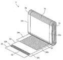
- FIG. 5 is a perspective view showing a part of the winding group.
- FIG. 6 is a graph showing the DCR increase rate of the lithium ion secondary batteries of Example 8, Comparative Example 1 and Comparative Example 4.
- the positive electrode 34 for a lithium ion secondary battery according to the first embodiment shown in FIG. 1 includes a positive electrode current collector 34a and a layered structure 34b provided on the positive electrode current collector 34a.
- the positive electrode current collector 34a is formed of an arbitrary material that has high conductivity and does not alloy with lithium ions.
- the positive electrode current collector 34a has a plate-like (sheet-like) shape having a second surface 342 which is an opposite surface of the first surface 341 and the first surface 341, but the shape of the positive electrode current collector 34a. Is not limited to this.
- an aluminum foil can be used as the positive electrode current collector 34a.
- a layered structure 34b is provided on each of the first surface 341 and the second surface 342 of the positive electrode current collector 34a. As shown in FIG. 1, a portion 34c in which the layered structure 34b is not provided (hereinafter, referred to as a “positive electrode current collector exposed portion”) 34c is provided at one end of the positive electrode current collector 34a.
- the layered structure 34b provided on the first surface 341 of the positive electrode current collector 34a will be described. Since the same description applies to the layered structure 34b provided on the second surface 342 of the positive electrode current collector 34a, the description of the layered structure 34b provided on the second surface 342 of the positive electrode current collector 34a Is omitted.
- the layered structure 34b is composed of two layers laminated in a direction perpendicular to the first surface 341 of the positive electrode current collector 34a. Of the two layers, the layer directly formed on the first surface 341 of the positive electrode current collector 34a is called the innermost layer 52, and the layer formed on the innermost layer 52 is called the outermost layer 51.
- the outermost layer 51 has the following equation (1): Li 1 + X M A O 2 (1) (During the ceremony, X satisfies ⁇ 0.15 ⁇ X ⁇ 0.15.
- M A represents an element group including Ni, Co and Mn, Ni in all the elements constituting the M A, the proportion of Co and Mn, respectively, are a (mol%), b ( mol%), c (mol%), a, b and c are 0 ⁇ a / (B + c) ⁇ 1, 1 ⁇ b / c ⁇ 2)
- the first positive electrode active material Since ⁇ 0.15 ⁇ X ⁇ 0.15, the first positive electrode active material has high true density and high reversibility.
- the lithium ion secondary battery using the positive electrode 34 for the lithium ion secondary battery according to the first embodiment has high safety.
- the first positive electrode active material has a composition satisfying 0 ⁇ a / (b + c) ⁇ 1 and 1 ⁇ b / c, so that the discharge capacity of the lithium ion secondary battery due to charging and discharging can be increased. It is possible to suppress a decrease and an increase in DC internal resistance.
- the present inventor considers this reason as follows.
- the first positive electrode active material satisfying 0 ⁇ a / (b + c) ⁇ 1 and 1 ⁇ b / c allows the charge / discharge reaction to proceed smoothly.
- the charge / discharge reaction preferentially occurs on the surface (outer surface) of the layered structure 34b farthest from the positive electrode current collector 34a.
- the lithium-ion secondary battery can maintain the discharge capacity and DC internal resistance over many charge / discharge cycles.
- the cost of the positive electrode for the lithium ion secondary battery is reduced, and the safety of the lithium ion secondary battery is improved.
- M A is, Zr, Ti, Cr, Fe , Cu, Zn, Ge, Sn, Mg, Ag, Ta, Nb, B, P, Ca, may further comprise at least one of Sr and Ba. If M A contains Zr, it reduces the internal resistance of the lithium ion secondary battery at low temperature.
- the content of Zr may be 0.1 to 2.0 mol%, particularly 0.2 to 1.0 mol%, based on the total amount of Ni, Co and Mn.
- the ratio of elements other than Ni, Co and Mn in all the elements constituting the M A is, 10 mol% or less, in particular, may be less 3 mol%. As a result, it is possible to sufficiently suppress a decrease in the discharge capacity of the lithium ion secondary battery and an increase in the DC internal resistance due to charging and discharging.
- the outermost layer 51 may further contain a binder and a conductive agent.
- binder for example, polyvinylidene fluoride (PVdF), polytetrafluoroethylene (PTFE), polyethylene, polystyrene, polybutadiene, polyacrylonitrile, polyvinyl fluoride, propylene polyvinyl fluoride, chloroprene fluoride, butyl rubber, nitrile rubber, styrene butadiene rubber, Polysulfide rubber, nitrocellulose, cyanoethyl cellulose, various latexes, acrylic resins, or mixtures thereof can be used.
- PVdF polyvinylidene fluoride
- PTFE polytetrafluoroethylene
- polyethylene polystyrene
- polybutadiene polyacrylonitrile
- polyvinyl fluoride propylene polyvinyl fluoride
- chloroprene fluoride butyl rubber
- nitrile rubber nitrile rubber
- styrene butadiene rubber Polysul
- a carbonaceous material can be used as the conductive agent.
- the carbonaceous material may be crystalline carbon, amorphous carbon, or a mixture thereof.
- crystalline carbon include artificial graphite, natural graphite (eg, scaly graphite), or mixtures thereof.
- amorphous carbon include carbon black (eg, acetylene black, ketjen black, channel black, furnace black, lamp black, thermal black, or mixtures thereof).
- the outermost layer 51 may have a thickness of 5 ⁇ m to 50 ⁇ m. As a result, it is possible to sufficiently suppress a decrease in the discharge capacity of the lithium ion secondary battery and an increase in the DC internal resistance due to charging and discharging.
- the innermost layer 52 has the following equation (2): Li 1 + Y M B O 2 (2) (During the ceremony, Y satisfies ⁇ 0.15 ⁇ Y ⁇ 0.15.
- M B represents an element group including Ni, Co, and at least one of Mn and Al) It may contain the second positive electrode active material represented by.
- the second positive electrode active material Since ⁇ 0.15 ⁇ Y ⁇ 0.15, the second positive electrode active material has high true density and high reversibility.
- the second positive electrode active material has a high stability in high thermal stability and a high potential state. Therefore, the lithium ion secondary battery using the positive electrode 34 for the lithium ion secondary battery according to the first embodiment has high safety.
- d (mol%), e (mol%) is expressed as f (mol%) and g (mol%).
- d, e, f and g satisfy 0 ⁇ d, 0 ⁇ e, 0 ⁇ f, 0 ⁇ g and 0 ⁇ f + g. Further, d, e, f and g may satisfy 1 ⁇ d / (e + f + g) ⁇ 4.
- the discharge capacity of the lithium ion secondary battery is reduced due to charging and discharging.
- the increase in DC internal resistance can be further suppressed.
- M B is, Zr, Ti, Cr, Fe , Cu, Zn, Ge, Sn, Mg, Ag, Ta, Nb, B, P, Ca, may further comprise at least one of Sr and Ba. If M B includes Zr, it reduces the internal resistance of the lithium ion secondary battery at low temperature.
- the content of Zr may be 0.1 to 2.0 mol%, particularly 0.2 to 1.0 mol%, based on the total amount of Ni, Co, Mn and Al. Further, Ni in all the elements constituting the M B, Co, the ratio of elements other than Mn and Al, 10 mol% or less, in particular, may be less 3 mol%. As a result, the discharge capacity of the lithium ion secondary battery can be sufficiently improved.
- the innermost layer 52 may further contain a binder and a conductive agent in the same manner as the outermost layer 51.
- the layered structure 34b in the first embodiment can be formed, for example, as follows.
- the first positive electrode active material, the conductive agent and the binder are dispersed in a solvent (for example, N-methyl-2-pyrrolidone (NMP), water) to prepare a paste-like or slurry-like first composition.
- a paste-like or slurry-like second composition is prepared from the second positive electrode active material, the conductive agent and the binder.
- the second composition is applied to the first surface 341 of the positive electrode current collector 34a, dried, and if necessary, subjected to calendar treatment to form the innermost layer 52.
- the first composition is applied onto the innermost layer 52, dried and, if necessary, calendared to form the outermost layer 51.
- the layered structure 34b is formed.
- the first composition and the second composition are simultaneously applied by a slot die coating method or the like and dried to form the outermost layer 51 and the innermost layer 52. You can also do it.
- the amount of each element in the first positive electrode active material and the second positive electrode active material can be measured by the ICP (Inductive Coupled Plasma) method.
- the positive electrode 34 for a lithium ion secondary battery according to the second embodiment shown in FIG. 2 includes a positive electrode current collector 34a and a layered structure 34b formed on the positive electrode current collector 34a.
- the positive electrode current collector 34a in the positive electrode 34 for a lithium ion secondary battery according to the second embodiment is the same as the positive electrode current collector 34a in the positive electrode 34 for a lithium ion secondary battery according to the first embodiment. Therefore, the description thereof will be omitted.
- a layered structure 34b is provided on each of the first surface 341 and the second surface 342 of the positive electrode current collector 34a.
- the positive electrode current collector 34a has a positive electrode current collector exposed portion 34c in which the layered structure 34b is not provided.
- the layered structure 34b provided on the first surface 341 of the positive electrode current collector 34a will be described. Since the same description applies to the layered structure 34b provided on the second surface 342 of the positive electrode current collector 34a, the description of the layered structure 34b provided on the second surface 342 of the positive electrode current collector 34a Is omitted.
- the layered structure 34b is composed of three layers laminated in a direction perpendicular to the first surface 341 of the positive electrode current collector 34a.
- the layer directly formed on the first surface 341 of the positive electrode current collector 34a is called the innermost layer 52
- the layer formed on the innermost layer 52 is called the intermediate layer 53
- the intermediate layer 53 is called.
- the layer formed on the top is called the outermost layer 51.
- outermost layer 51 and the innermost layer 52 in the second embodiment are the same as the outermost layer 51 and the innermost layer 52 in the first embodiment, the description thereof will be omitted.
- the intermediate layer 53 has the following equation (3): Li 1 + Z M C O 2 (3) (During the ceremony, Z satisfies ⁇ 0.15 ⁇ Z ⁇ 0.15.
- M C represents Ni, Co, and the element group including at least one of Mn and Al) It may contain a third positive electrode active material represented by.
- the third positive electrode active material Since ⁇ 0.15 ⁇ Z ⁇ 0.15, the third positive electrode active material has high true density and high reversibility.
- the lithium ion secondary battery using the positive electrode 34 for the lithium ion secondary battery according to the second embodiment has high safety.
- the amount of each element in the intermediate layer 53 can be measured by the ICP method.
- the intermediate layer 53 may further contain a binder and a conductive agent in the same manner as the outermost layer 51 and the innermost layer 52.
- the intermediate layer 53 may contain the conductive agent in a weight ratio higher than the weight ratio of the conductive agent in the outermost layer 51 and the innermost layer 52, and in a weight ratio lower than the weight ratio of the binder in the outermost layer 51 and the innermost layer 52.
- a binder may be contained, and the third positive electrode active material may be contained in a weight ratio lower than the weight ratio of the first positive electrode active material in the outermost layer and the weight ratio of the second positive electrode active material in the innermost layer.
- the intermediate layer 53 containing the conductive agent in a high weight ratio can hold more electrolytic solution than the outermost layer 51 and the innermost layer 52, and the outermost layer 51 and the innermost layer 52 can be retained when the lithium ion secondary battery is discharged.
- the electrolytic solution can be supplied to the battery. Therefore, the ionic conductivity in the layered structure 34b can be improved.
- the intermediate layer 53 may have a thickness smaller than that of the outermost layer 51 and the innermost layer 52.
- the layered structure 34b in the second embodiment can be formed, for example, as follows.
- the first positive electrode active material, the conductive agent and the binder are dispersed in a solvent to prepare a paste-like or slurry-like first composition.
- a paste-like or slurry-like second composition is prepared from the second positive electrode active material, the conductive agent and the binder, and a paste-like or slurry-like third is prepared from the third positive electrode active material, the conductive agent and the binder.
- the second composition is applied to the first surface 341 of the positive electrode current collector 34a, dried, and if necessary, subjected to calendar treatment to form the innermost layer 52.
- the third composition is then applied onto the innermost layer 52, dried and, if necessary, calendared to form the intermediate layer 53. Further, the first composition is applied onto the intermediate layer 53, dried and, if necessary, calendared to form the outermost layer 51. As a result, the layered structure 34b is formed.
- the first composition, the second composition and the third composition are simultaneously applied and dried by a slot die coating method or the like. , The outermost layer 51, the innermost layer 52, and the intermediate layer 53 can also be formed.
- the layered structure 34b is provided on each of the first surface 341 and the second surface 342 of the positive electrode current collector 34a, but the first of the positive electrode current collectors 34a.
- the layered structure 34b may be provided on only one of the surface 341 and the second surface 342. That is, the layered structure 34b is provided on at least one of the first surface 341 and the second surface 342 of the positive electrode current collector 34a.
- the layered structure 34b is composed of two and three layers, respectively, but the layered structure 34b may be composed of four or more layers. That is, the layered structure 34b is the outermost layer 51, which is the layer farthest from the first surface 341 of the positive electrode current collector 34a in the layered structure 34b, and the first positive electrode current collector 34a in the layered structure 34b. At least the innermost layer 52, which is the layer closest to the surface 341, may be included, and at least one intermediate layer 53 may be further included between the outermost layer 51 and the innermost layer 52.
- the positive electrode for a lithium ion secondary battery according to the above embodiment can be applied to any lithium ion secondary battery.
- an example of a lithium ion secondary battery using the positive electrode for the lithium ion secondary battery according to the above embodiment will be described.
- the lithium ion secondary battery 100 shown in FIGS. 3 and 4 is a square battery. Further, the lithium ion secondary battery 100 includes a battery can 1 and a battery lid 6.
- the battery can 1 has a side surface including a rectangular bottom surface 1d, a pair of opposing wide side surfaces 1b having a relatively large area rising from the bottom surface 1d, and a pair of opposing narrow side surfaces 1c having a relatively small area, and a wide surface. It has an opening 1a that is open upward at the upper ends of the side surface 1b and the narrow side surface 1c.
- the upper direction means the Z direction in FIGS. 3 and 4.
- the opening 1a of the battery can 1 is sealed by the battery lid 6.
- the battery lid 6 has a substantially rectangular flat plate shape, and is welded so as to close the opening 1a of the battery can 1 to seal the battery can 1.
- the battery lid 6 is integrally provided with a gas discharge valve 10.
- the gas discharge valve 10 When the pressure inside the battery can 1 rises, the gas discharge valve 10 is cleaved, gas is discharged from the inside of the battery can 1, and the pressure inside the battery can 1 decreases. As a result, the safety of the lithium ion secondary battery 100 is ensured.
- the battery lid 6 is provided with a liquid injection port 9 for injecting an electrolytic solution into the battery can 1.
- the liquid injection port 9 is sealed by the liquid injection plug 11 after the electrolytic solution is injected into the battery can 1.
- the liquid injection plug 11 is joined to the battery lid 6 by laser welding to seal the liquid injection port 9, and seals the lithium ion secondary battery 100.
- the battery lid 6 is further provided with a positive electrode side through hole 46 and a negative electrode side through hole 26.
- a positive electrode external terminal 14 and a negative electrode external terminal 12 are provided above the battery lid 6.
- a positive electrode current collector plate 44 and a negative electrode current collector plate 24 are provided below the battery lid 6 and inside the battery can 1.
- Examples of the material for forming the positive electrode external terminal 14 and the positive electrode current collector plate 44 include an aluminum alloy, and examples of the material for forming the negative electrode external terminal 12 and the negative electrode current collector plate 24 include a copper alloy.
- the positive electrode external terminal 14 and the negative electrode external terminal 12 each have a welded joint portion to be welded to a bus bar or the like.
- the welded joint has a rectangular parallelepiped block shape that projects upward from the battery lid 6.
- the lower surface of the welded joint faces the surface of the battery lid 6, and the upper surface of the welded joint is located at a predetermined height position and is substantially parallel to the battery lid 6.
- the positive electrode current collector plate 44 has a rectangular plate-shaped positive electrode current collector plate base 41 facing the lower surface of the battery lid 6 and a bottom surface 1d side along the wide side surface 1b of the battery can 1 from the side end of the positive electrode current collector plate base 41. It has a positive electrode side connecting end 42 extending toward.
- the negative electrode current collector plate 24 has a rectangular plate-shaped negative electrode current collector plate base 21 facing the lower surface of the battery lid 6 and a side end of the negative electrode current collector plate base 21 along the wide side surface 1b of the battery can 1. It has a negative electrode side connection end 22 extending toward the bottom surface 1d side.
- a positive electrode side opening hole 43 and a negative electrode side opening hole 23 are formed in the positive electrode current collector plate base 41 and the negative electrode current collector plate base 21, respectively.
- a positive electrode connecting portion 14a and a negative electrode connecting portion 12a are provided so as to project from the lower surfaces of the positive electrode external terminal 14 and the negative electrode external terminal 12, respectively.
- the positive electrode connecting portion 14a and the negative electrode connecting portion 12a are integrally formed with the positive electrode external terminal 14 and the negative electrode external terminal 12, respectively.
- the positive electrode connection portion 14a has a cylindrical shape that can be inserted into the positive electrode side through hole 46 of the battery lid 6 and the positive electrode side opening hole 43 of the positive electrode current collector plate base 41.
- the negative electrode connection portion 12a has a cylindrical shape that can be inserted into the negative electrode side through hole 26 of the battery lid 6 and the negative electrode side opening hole 23 of the negative electrode current collector plate base portion 21.
- the positive electrode connection portion 14a is arranged so as to pass through the positive electrode side through hole 46 of the battery lid 6 and the positive electrode side opening hole 43 of the positive electrode current collector plate base 41, and penetrates the battery lid 6 and the positive electrode current collector plate base 41.
- the tip of the positive electrode connection portion 14a is crimped, and the positive electrode external terminal 14 and the positive electrode current collector plate 44 are integrally fixed to the battery lid 6.
- the negative electrode connection portion 12a is arranged so as to pass through the negative electrode side through hole 26 of the battery lid 6 and the negative electrode side opening hole 23 of the negative electrode current collector plate base portion 21, and connects the battery lid 6 and the negative electrode current collector plate base portion 21. Penetrate.
- the tip of the negative electrode connecting portion 12a is crimped, and the negative electrode external terminal 12 and the negative electrode current collector plate 24 are integrally fixed to the battery lid 6.
- the positive electrode external terminal 14 is electrically connected to the winding group 3 described later via the positive electrode connecting portion 14a and the positive electrode current collector plate 44.
- the negative electrode external terminal 12 is electrically connected to the winding group 3 via the negative electrode connecting portion 12a and the negative electrode current collector plate 24.
- the winding group 3 is passed through the positive electrode external terminal 14, the positive electrode connection portion 14a and the positive electrode current collector plate 44, and the negative electrode external terminal 12, the negative electrode connection portion 12a and the negative electrode current collector plate 24. Electricity is supplied to the external load from.
- each of the positive electrode external terminal 14 and the negative electrode external terminal 12 and the battery lid A gasket 5 is provided between the positive electrode current collector plate 44 and the negative electrode current collector plate 24, and an insulating plate 7 is provided between each of the positive electrode current collector plate 44 and the negative electrode current collector plate 24 and the battery lid 6.
- the material for forming the insulating plate 7 and the gasket 5 include a resin material having an insulating property such as polybutylene terephthalate, polyphenylene sulfide, and perfluoroalkoxy alkane resin.
- the electrolytic solution, the winding group 3, and the insulating protective film 2 are stored in the battery can 1.
- the electrolytic solution is injected into the battery can 1 from the injection port 9.
- a non-aqueous electrolytic solution in which a lithium salt such as lithium hexafluorophosphate (LiPF 6 ) is dissolved in a carbonic acid ester-based organic solvent such as ethylene carbonate can be used.
- the winding group 3 has a negative electrode 32, a positive electrode 34, and two separators 33 and 35.
- the separator 35, the negative electrode 32, the separator 33, and the positive electrode 34 are stacked in this order and wound flat.
- the separator 35 is located on the outermost circumference of the winding group 3, and the negative electrode electrode 32 is located inside the separator 35.
- the two separators 33 and 35 electrically insulate the positive electrode 34 and the negative electrode 32.
- the winding group 3 has a pair of opposite end faces 3a and 3b perpendicular to the winding axis and a side surface 3c between the pair of end faces.
- the side surface 3c has a pair of curved portions facing each other having a semicircular cross section, and a flat surface portion continuously formed between the pair of curved portions.
- the winding group 3 is arranged in the battery can 1 so that the flat surface portion of the side surface 3c and the wide side surface 1b of the battery can 1 are substantially parallel to each other.
- the positive electrode electrode 34 As the positive electrode electrode 34, the positive electrode for a lithium ion secondary battery according to the above embodiment is used.
- the positive electrode current collector exposed portion 34c of the positive electrode current collector 34a (see FIGS. 1 and 2) is provided at or near the end surface 3a of the winding group 3.
- the positive electrode current collector exposed portion 34c faces the positive electrode side connection end 42 of the positive electrode current collector plate 44 and is electrically connected to the positive electrode current collector plate 44.
- the negative electrode electrode 32 has a negative electrode current collector and a negative electrode mixture layer 32b formed on both sides of the negative electrode current collector.
- the negative electrode current collector is formed from any material that is highly conductive and does not alloy with lithium ions. At one end of the negative electrode current collector, a portion (hereinafter referred to as “exposed portion of the negative electrode current collector”) 32c that is not covered with the negative electrode mixture layer 32 is provided.
- the negative electrode current collector exposed portion 32c is provided on or near the end surface 3b of the winding group 3.
- the negative electrode current collector exposed portion 32c faces the negative electrode side connection end 22 of the negative current collector plate 24 and is electrically connected.
- the negative electrode mixture layer 32b contains a negative electrode active material.
- the negative electrode active material is formed from any material capable of inserting and removing lithium ions. Examples of such materials include carbon materials such as natural graphite, artificial graphite, hard carbonized carbon (hard carbon), carbon easily graphitized (soft carbon), graphite coated with amorphous carbon, and as a conductive auxiliary agent.
- a mixture of carbon black eg, acetylene black, ketjen black, channel black, furnace black, lamp black, thermal black
- graphite a composite obtained by coating the mixture with amorphous carbon, graphite and difficulty. Examples thereof include a mixture with carbonized carbon, easily graphitized carbon or a metal oxide (for example, iron oxide, copper oxide), and a mixture thereof.
- the negative electrode mixture layer 32b further contains a binder.
- a binder the same material as that exemplified for the binder used in the layered structure 34b of the positive electrode electrode 34 can be used.
- the negative electrode mixture layer 32b further has a thickener. Carboxymethyl cellulose can be used as the thickener.
- the total thickness of the negative electrode mixture layer 32b (that is, the total thickness of the two negative electrode mixture layers 32b formed on both sides of the negative electrode current collector) is not limited, but is usually 50 ⁇ m to 200 ⁇ m.
- the separators 33 and 35 have a function of preventing a short circuit between the positive electrode 34 and the negative electrode 32 and a function of holding a non-aqueous electrolytic solution.
- a porous sheet made of a resin such as polyethylene (PE), polypropylene (PP), polyester, cellulose, or polyamide, or a laminated sheet thereof (for example, a three-layer structure of PP / PE / PP). Sheet) can be used.
- a layer containing an inorganic material (for example, alumina particles) and a binder may be provided on one or both sides of the separators 33 and 35.
- the shaft core may be arranged on the innermost circumference of the winding group 3.
- a resin sheet wound with a resin sheet having a higher bending rigidity than any of the positive electrode current collector, the negative electrode current collector, and the separators 33 and 35 can be used.
- the insulating protective film 2 is wound around the winding group 3.
- a sheet made of a synthetic resin such as polypropylene (PP) can be used as the insulating protective film 2.
- the insulating protective film 2 may be a single sheet or a sheet in which a plurality of sheets are laminated.
- the winding axis of the insulating protective film 2 is perpendicular to the winding axis of the winding group 3 and parallel to the flat surface portion of the side surface 3c of the winding group 3.
- Li 1.0 Ni a Co b Mn c O 2 powder as a first cathode active material was prepared Li 1.0 Ni d Co e Mn f Al g O 2 powder as the second cathode active material.
- the values of a to g in each example were determined by ICP analysis. The results are shown in Table 1. Further, acetylene black was prepared as a conductive agent, and polyvinylidene fluoride (PVdF) was prepared as a binder.
- PVdF polyvinylidene fluoride
- the first positive electrode active material, the conductive agent and the binder were mixed in a weight ratio of 90: 5: 5.
- N-Methyl-2-pyrrolidone (NMP) was added to the obtained mixture to adjust the viscosity, and a first slurry was obtained.
- the second positive electrode active material, the conductive agent and the binder were mixed in a weight ratio of 90: 5: 5, and N-methyl-2-pyrrolidone (NMP) was added to the obtained mixture to adjust the viscosity, and the viscosity was adjusted. Two slurries were obtained.
- An aluminum foil with a thickness of 15 ⁇ m was prepared as the positive electrode current collector.
- the slot die coating method is used on both sides of the positive electrode current collector so that the layer of the second slurry is formed on both sides of the positive electrode current collector and the layer of the first slurry is formed on the layer of the second slurry.
- One slurry and a second slurry were applied.
- the layer of the first slurry and the layer of the second slurry were dried and pressed.
- a positive electrode positive electrode for a lithium ion secondary battery in which a layered structure consisting of an outermost layer containing a first positive electrode active material and an innermost layer containing a second positive electrode active material is formed on both sides of a positive electrode current collector is formed. Obtained.
- Natural graphite coated with amorphous carbon was prepared as the negative electrode active material, styrene-butadiene rubber (SBR) was prepared as the binder, and carboxymethyl cellulose (CMC) was prepared as the dispersant.
- SBR styrene-butadiene rubber
- CMC carboxymethyl cellulose
- the negative electrode active material, binder and dispersant were mixed in a weight ratio of 98: 1: 1. Ion-exchanged water was added to the obtained mixture to adjust the viscosity, and a negative electrode slurry was obtained.
- a copper foil having a thickness of 10 ⁇ m was prepared as a negative electrode current collector.
- a negative electrode slurry was applied to both sides of the negative electrode current collector by a slot die coating method to form a negative electrode mixture layer. Then, the negative electrode mixture layer was dried and pressed. As a result, a negative electrode was obtained.
- the separator, the negative electrode, another separator, and the positive electrode were stacked in this order and wound.
- a winding group as shown in FIG. 5 was prepared.
- ethylene carbonate (EC) and dimethyl carbonate (DMC) were mixed at a volume ratio of 1: 2, and LiPF 6 was dissolved in the obtained mixed solution.
- a 1.0 mol / L LiPF 6 solution was obtained as a non-aqueous electrolytic solution.
- a lithium ion secondary battery as shown in FIGS. 3 and 4 was produced.
- Example 12 Li 1.0 Ni a Co b Mn c O 2 powder as a first cathode active material was prepared Li 1.0 Ni d Co e Mn f Al g O 2 powder as the second cathode active material.
- the values of a to g obtained by ICP analysis are as shown in Table 1.
- a first slurry and a second slurry were prepared in the same manner as in Examples 1 to 11.
- Li 1.0 Ni 0.6 Co 0.2 Mn 0.2 O 2 powder was prepared as the third positive electrode active material.
- the third positive electrode active material, the conductive agent and the binder were mixed in a weight ratio of 90: 5: 5.
- NMP N-Methyl-2-pyrrolidone
- a layer of the second slurry is formed on both sides of the positive electrode current collector, a layer of the third slurry is formed on the layer of the second slurry, and a layer of the first slurry is formed on the layer of the third slurry.
- the first slurry, the second slurry and the third slurry were applied to both sides of the positive electrode current collector by the slot die coating method. Then, drying and pressing were carried out in the same manner as in Examples 1 to 11.
- a layered structure consisting of an outermost layer containing the first positive electrode active material, an innermost layer containing the second positive electrode active material, and an intermediate layer containing the third positive electrode active material between the outermost layer and the innermost layer is a positive electrode collection. Positive electrode electrodes formed on both sides of the electric body were obtained.
- a lithium ion secondary battery was produced in the same manner as in Examples 1 to 11.
- Example 13 A lithium ion secondary battery was produced in the same manner as in Example 12 except that the third positive electrode active material, the conductive agent, and the binder were mixed in a weight ratio of 45:50: 5.
- Li 1.0 Ni a Co b Mn c O 2 powder as a first cathode active material was prepared Li 1.0 Ni d Co e Mn f Al g O 2 powder as the second cathode active material.
- the values of a to g obtained by ICP analysis are as shown in Table 1. Using these first positive electrode active material and second positive electrode active material, a lithium ion secondary battery was produced in the same manner as in Examples 1 to 11.
- Comparative Example 4 Li 1.0 Ni 0.33 Co 0.33 Mn 0.33 O 2 powder and Li 1.0 Ni 0.5 Co 0.2 Mn 0.3 O 2 powder were mixed at a weight ratio of 1: 1.
- the molar ratio of Li, Ni, Co and Mn was 1.0: 0.416: 0.267: 0.317.
- This mixed powder was used as the first positive electrode active material and the second positive electrode active material. Further, acetylene black and graphite were used as the conductive agent, and PVdF was used as the binder.
- NMP N-Methyl-2-pyrrolidone
- a lithium ion secondary battery was produced in the same manner as in Examples 1 to 11.
- the values a to g in Table 1 are values obtained by analyzing the mixed powder by the ICP method as described above.
- Comparative Example 5 The same as in Examples 1 to 11 except that Li 1.0 Co 1.0 O 2 powder was used as the first positive electrode active material and Li 1.0 Ni 1.0 O 2 powder was used as the second positive electrode active material. , A lithium ion secondary battery was manufactured.
- the lithium ion secondary battery was charged from SOC 0% to SOC 50% by a constant current-constant voltage (CC-CV) method.
- the charging current during constant current charging was 1 CA.
- the lithium ion battery was discharged at a constant current of 10 CA for 10 seconds, and the voltage drop value due to the discharge was measured.
- the same constant current discharge was performed with discharge currents of 15 CA and 20 CA.
- the discharge current was plotted on the horizontal axis and the voltage drop value was plotted on the vertical axis, and the slope of the graph was defined as the initial DCR.
- FIG. 6 shows the DCR increase rate of the lithium ion secondary batteries of Example 8, Comparative Example 1 and Comparative Example 4.
- Table 2 shows the capacity retention rate and DCR increase rate of the lithium ion secondary batteries of each Example and Comparative Example after a total of 1400 hours of charge / discharge cycle.
- the lithium ion secondary batteries of Examples 1 to 13 have the same initial battery capacity as the lithium ion secondary batteries of Comparative Examples 1 to 6, but have a higher capacity retention rate than those of Comparative Examples 1 to 6. Moreover, the DCR increase rate was low.
- the first positive electrode active material has a composition satisfying 0 ⁇ a / (b + c) ⁇ 1 and 1 ⁇ b / c, so that lithium ions due to charging and discharging are obtained. It was shown that the decrease in the discharge capacity of the secondary battery and the increase in the DC internal resistance can be suppressed.
- the lithium ion secondary batteries of Examples 1, 7 to 9 and 11 had a smaller decrease in discharge capacity and an increase in DC internal resistance than the lithium ion secondary batteries of Example 10. From this, it is shown that when the second positive electrode active material satisfies 1 ⁇ d / (e + f + g) ⁇ 4, it is possible to further suppress a decrease in the discharge capacity of the lithium ion secondary battery and an increase in the DC internal resistance due to charging and discharging. It was.
Landscapes
- Chemical & Material Sciences (AREA)
- Chemical Kinetics & Catalysis (AREA)
- Electrochemistry (AREA)
- General Chemical & Material Sciences (AREA)
- Inorganic Chemistry (AREA)
- Engineering & Computer Science (AREA)
- Composite Materials (AREA)
- Materials Engineering (AREA)
- Manufacturing & Machinery (AREA)
- Battery Electrode And Active Subsutance (AREA)
- Secondary Cells (AREA)
Priority Applications (6)
| Application Number | Priority Date | Filing Date | Title |
|---|---|---|---|
| JP2021556156A JP7461964B2 (ja) | 2019-11-15 | 2020-11-12 | リチウムイオン二次電池用正極、リチウムイオン二次電池及び方法 |
| CN202080064687.9A CN114402459B (zh) | 2019-11-15 | 2020-11-12 | 锂离子二次电池用正极和锂离子二次电池 |
| CN202410816010.6A CN118676305A (zh) | 2019-11-15 | 2020-11-12 | 锂离子二次电池用正极及其制造方法和锂离子二次电池 |
| EP20888111.0A EP4060759A4 (en) | 2019-11-15 | 2020-11-12 | POSITIVE ELECTRODE FOR LITHIUM-ION SECONDARY BATTERIES, AND LITHIUM-ION SECONDARY BATTERY |
| US17/760,913 US12255319B2 (en) | 2019-11-15 | 2020-11-12 | Positive electrode for lithium ion secondary batteries, and lithium ion secondary battery |
| JP2024047733A JP2024075723A (ja) | 2019-11-15 | 2024-03-25 | リチウムイオン二次電池用正極、リチウムイオン二次電池及び方法 |
Applications Claiming Priority (2)
| Application Number | Priority Date | Filing Date | Title |
|---|---|---|---|
| JP2019207241 | 2019-11-15 | ||
| JP2019-207241 | 2019-11-15 |
Publications (1)
| Publication Number | Publication Date |
|---|---|
| WO2021095818A1 true WO2021095818A1 (ja) | 2021-05-20 |
Family
ID=75912721
Family Applications (1)
| Application Number | Title | Priority Date | Filing Date |
|---|---|---|---|
| PCT/JP2020/042320 Ceased WO2021095818A1 (ja) | 2019-11-15 | 2020-11-12 | リチウムイオン二次電池用正極、及びリチウムイオン二次電池 |
Country Status (5)
| Country | Link |
|---|---|
| US (1) | US12255319B2 (https=) |
| EP (1) | EP4060759A4 (https=) |
| JP (2) | JP7461964B2 (https=) |
| CN (2) | CN114402459B (https=) |
| WO (1) | WO2021095818A1 (https=) |
Cited By (2)
| Publication number | Priority date | Publication date | Assignee | Title |
|---|---|---|---|---|
| JPWO2024047854A1 (https=) * | 2022-09-01 | 2024-03-07 | ||
| WO2025142877A1 (ja) * | 2023-12-27 | 2025-07-03 | パナソニックIpマネジメント株式会社 | 電極および電池 |
Families Citing this family (2)
| Publication number | Priority date | Publication date | Assignee | Title |
|---|---|---|---|---|
| EP4060759A4 (en) * | 2019-11-15 | 2023-12-06 | Vehicle Energy Japan Inc. | POSITIVE ELECTRODE FOR LITHIUM-ION SECONDARY BATTERIES, AND LITHIUM-ION SECONDARY BATTERY |
| JP7665440B2 (ja) * | 2021-06-23 | 2025-04-21 | パナソニックエナジー株式会社 | 非水電解質二次電池 |
Citations (10)
| Publication number | Priority date | Publication date | Assignee | Title |
|---|---|---|---|---|
| JPH10255762A (ja) | 1997-03-10 | 1998-09-25 | Sanyo Electric Co Ltd | リチウム電池 |
| JP2014026777A (ja) * | 2012-07-25 | 2014-02-06 | Toyota Motor Corp | 非水電解質二次電池と、該二次電池用の正極の製造方法 |
| JP2015115244A (ja) * | 2013-12-13 | 2015-06-22 | 株式会社Gsユアサ | リチウム二次電池用正極、リチウム二次電池、バッテリーモジュール、及びバッテリーモジュールを搭載した自動車 |
| CN108933242A (zh) * | 2018-07-10 | 2018-12-04 | 邓丽萍 | 一种锂离子电池混合正极的制备方法 |
| JP2019029205A (ja) * | 2017-07-31 | 2019-02-21 | パナソニック株式会社 | 非水電解質二次電池用正極、及び非水電解質二次電池 |
| JP2019140039A (ja) * | 2018-02-14 | 2019-08-22 | トヨタ自動車株式会社 | 非水電解質二次電池 |
| JP2019192470A (ja) * | 2018-04-24 | 2019-10-31 | トヨタ自動車株式会社 | 電極とこれを用いた電池 |
| CN110429252A (zh) * | 2019-07-19 | 2019-11-08 | 宁德新能源科技有限公司 | 正极及电化学装置 |
| JP2019207241A (ja) | 2015-11-02 | 2019-12-05 | ティーディーケイ・エレクトロニクス・アクチェンゲゼルシャフトTdk Electronics Ag | センサ素子およびセンサ素子を製造するための方法 |
| US20200006767A1 (en) * | 2018-06-28 | 2020-01-02 | Contemporary Amperex Technology Co., Limited | Positive electrode plate and lithium ion battery |
Family Cites Families (15)
| Publication number | Priority date | Publication date | Assignee | Title |
|---|---|---|---|---|
| US7691535B2 (en) * | 2002-03-27 | 2010-04-06 | Gs Yuasa Corporation | Active substance of positive electrode and non-aqueous electrolyte battery containing the same |
| JP2005209496A (ja) * | 2004-01-23 | 2005-08-04 | Matsushita Electric Ind Co Ltd | 非水電解質二次電池 |
| JP2006196247A (ja) * | 2005-01-12 | 2006-07-27 | Matsushita Electric Ind Co Ltd | リチウム二次電池用負極およびリチウム二次電池 |
| JP5032800B2 (ja) | 2005-07-14 | 2012-09-26 | パナソニック株式会社 | リチウム二次電池用正極およびそれを用いたリチウム二次電池 |
| JP5219422B2 (ja) * | 2007-07-31 | 2013-06-26 | 三洋電機株式会社 | 非水電解質二次電池 |
| JP4972624B2 (ja) * | 2008-09-30 | 2012-07-11 | 日立ビークルエナジー株式会社 | リチウム二次電池用正極材料及びそれを用いたリチウム二次電池 |
| KR101050438B1 (ko) * | 2008-11-10 | 2011-07-19 | 주식회사 코캄 | 안전성이 우수한 리튬 이차전지용 양극 활물질 및 그 제조방법과 이를 포함하는 리튬 이차전지 |
| CN104600244A (zh) * | 2014-12-29 | 2015-05-06 | 惠州市恒泰科技有限公司 | 一种多层正极片、正极片的制作方法以及锂离子电池 |
| KR101783445B1 (ko) * | 2015-03-17 | 2017-09-29 | 주식회사 엘지화학 | 다층 구조 전극 및 이를 포함하는 리튬 이차전지 |
| JP2016213057A (ja) | 2015-05-08 | 2016-12-15 | 凸版印刷株式会社 | 非水電解液二次電池用負極、その製造方法、及び非水電解液二次電池 |
| JP6819859B2 (ja) * | 2016-10-27 | 2021-01-27 | 住友金属鉱山株式会社 | 非水系電解質二次電池用正極材料、該正極材料を用いた非水系電解質二次電池、および非水系電解質二次電池用正極材料の製造方法。 |
| WO2018179898A1 (ja) * | 2017-03-29 | 2018-10-04 | パナソニックIpマネジメント株式会社 | 二次電池 |
| CN110603668A (zh) | 2017-05-31 | 2019-12-20 | 松下知识产权经营株式会社 | 二次电池用正极和二次电池 |
| WO2019187128A1 (ja) | 2018-03-30 | 2019-10-03 | 株式会社 東芝 | 電池及び電池パック |
| EP4060759A4 (en) * | 2019-11-15 | 2023-12-06 | Vehicle Energy Japan Inc. | POSITIVE ELECTRODE FOR LITHIUM-ION SECONDARY BATTERIES, AND LITHIUM-ION SECONDARY BATTERY |
-
2020
- 2020-11-12 EP EP20888111.0A patent/EP4060759A4/en active Pending
- 2020-11-12 JP JP2021556156A patent/JP7461964B2/ja active Active
- 2020-11-12 CN CN202080064687.9A patent/CN114402459B/zh active Active
- 2020-11-12 WO PCT/JP2020/042320 patent/WO2021095818A1/ja not_active Ceased
- 2020-11-12 US US17/760,913 patent/US12255319B2/en active Active
- 2020-11-12 CN CN202410816010.6A patent/CN118676305A/zh active Pending
-
2024
- 2024-03-25 JP JP2024047733A patent/JP2024075723A/ja active Pending
Patent Citations (10)
| Publication number | Priority date | Publication date | Assignee | Title |
|---|---|---|---|---|
| JPH10255762A (ja) | 1997-03-10 | 1998-09-25 | Sanyo Electric Co Ltd | リチウム電池 |
| JP2014026777A (ja) * | 2012-07-25 | 2014-02-06 | Toyota Motor Corp | 非水電解質二次電池と、該二次電池用の正極の製造方法 |
| JP2015115244A (ja) * | 2013-12-13 | 2015-06-22 | 株式会社Gsユアサ | リチウム二次電池用正極、リチウム二次電池、バッテリーモジュール、及びバッテリーモジュールを搭載した自動車 |
| JP2019207241A (ja) | 2015-11-02 | 2019-12-05 | ティーディーケイ・エレクトロニクス・アクチェンゲゼルシャフトTdk Electronics Ag | センサ素子およびセンサ素子を製造するための方法 |
| JP2019029205A (ja) * | 2017-07-31 | 2019-02-21 | パナソニック株式会社 | 非水電解質二次電池用正極、及び非水電解質二次電池 |
| JP2019140039A (ja) * | 2018-02-14 | 2019-08-22 | トヨタ自動車株式会社 | 非水電解質二次電池 |
| JP2019192470A (ja) * | 2018-04-24 | 2019-10-31 | トヨタ自動車株式会社 | 電極とこれを用いた電池 |
| US20200006767A1 (en) * | 2018-06-28 | 2020-01-02 | Contemporary Amperex Technology Co., Limited | Positive electrode plate and lithium ion battery |
| CN108933242A (zh) * | 2018-07-10 | 2018-12-04 | 邓丽萍 | 一种锂离子电池混合正极的制备方法 |
| CN110429252A (zh) * | 2019-07-19 | 2019-11-08 | 宁德新能源科技有限公司 | 正极及电化学装置 |
Non-Patent Citations (1)
| Title |
|---|
| See also references of EP4060759A4 |
Cited By (3)
| Publication number | Priority date | Publication date | Assignee | Title |
|---|---|---|---|---|
| JPWO2024047854A1 (https=) * | 2022-09-01 | 2024-03-07 | ||
| WO2024047854A1 (ja) | 2022-09-01 | 2024-03-07 | ビークルエナジージャパン株式会社 | リチウムイオン二次電池用正極及びリチウムイオン二次電池 |
| WO2025142877A1 (ja) * | 2023-12-27 | 2025-07-03 | パナソニックIpマネジメント株式会社 | 電極および電池 |
Also Published As
| Publication number | Publication date |
|---|---|
| JP2024075723A (ja) | 2024-06-04 |
| CN114402459B (zh) | 2024-07-12 |
| EP4060759A4 (en) | 2023-12-06 |
| US20220352505A1 (en) | 2022-11-03 |
| EP4060759A1 (en) | 2022-09-21 |
| US12255319B2 (en) | 2025-03-18 |
| JP7461964B2 (ja) | 2024-04-04 |
| CN114402459A (zh) | 2022-04-26 |
| CN118676305A (zh) | 2024-09-20 |
| JPWO2021095818A1 (https=) | 2021-05-20 |
Similar Documents
| Publication | Publication Date | Title |
|---|---|---|
| JP7461964B2 (ja) | リチウムイオン二次電池用正極、リチウムイオン二次電池及び方法 | |
| CN111480250B (zh) | 锂离子二次电池用正极和使用它的锂离子二次电池 | |
| JP2012252969A (ja) | リチウムイオン二次電池 | |
| JP2000090932A (ja) | リチウム二次電池 | |
| JP5168535B2 (ja) | リチウム二次電池およびその製造方法 | |
| JP7528357B2 (ja) | リチウムイオン二次電池、及びリチウムイオン二次電池用負極の製造方法 | |
| JP2020113487A (ja) | リチウムイオン二次電池 | |
| JP7691504B2 (ja) | リチウムイオン二次電池 | |
| US20250379211A1 (en) | Negative electrode and battery | |
| US20260058126A1 (en) | Negative electrode and battery | |
| JP2013143262A (ja) | リチウムイオン二次電池 | |
| WO2010067410A1 (ja) | リチウムイオン電池およびその製造方法 | |
| US12506149B2 (en) | Secondary battery | |
| WO2024224859A1 (ja) | 電極及び電池 | |
| WO2022163578A1 (ja) | 非水電解質二次電池の充電方法、及び、充放電方法、並びに、非水電解質二次電池の充電システム | |
| CN119054124A (zh) | 锂离子二次电池 |
Legal Events
| Date | Code | Title | Description |
|---|---|---|---|
| 121 | Ep: the epo has been informed by wipo that ep was designated in this application |
Ref document number: 20888111 Country of ref document: EP Kind code of ref document: A1 |
|
| DPE2 | Request for preliminary examination filed before expiration of 19th month from priority date (pct application filed from 20040101) | ||
| ENP | Entry into the national phase |
Ref document number: 2021556156 Country of ref document: JP Kind code of ref document: A |
|
| NENP | Non-entry into the national phase |
Ref country code: DE |
|
| ENP | Entry into the national phase |
Ref document number: 2020888111 Country of ref document: EP Effective date: 20220615 |
|
| WWG | Wipo information: grant in national office |
Ref document number: 17760913 Country of ref document: US |