WO2021095818A1 - Positive electrode for lithium ion secondary batteries, and lithium ion secondary battery - Google Patents
Positive electrode for lithium ion secondary batteries, and lithium ion secondary battery Download PDFInfo
- Publication number
- WO2021095818A1 WO2021095818A1 PCT/JP2020/042320 JP2020042320W WO2021095818A1 WO 2021095818 A1 WO2021095818 A1 WO 2021095818A1 JP 2020042320 W JP2020042320 W JP 2020042320W WO 2021095818 A1 WO2021095818 A1 WO 2021095818A1
- Authority
- WO
- WIPO (PCT)
- Prior art keywords
- positive electrode
- ion secondary
- lithium ion
- current collector
- secondary battery
- Prior art date
Links
- HBBGRARXTFLTSG-UHFFFAOYSA-N Lithium ion Chemical compound [Li+] HBBGRARXTFLTSG-UHFFFAOYSA-N 0.000 title claims abstract description 99
- 229910001416 lithium ion Inorganic materials 0.000 title claims abstract description 99
- 239000007774 positive electrode material Substances 0.000 claims abstract description 56
- 229910052748 manganese Inorganic materials 0.000 claims abstract description 22
- 229910052759 nickel Inorganic materials 0.000 claims abstract description 17
- 229910052782 aluminium Inorganic materials 0.000 claims abstract description 13
- 239000011230 binding agent Substances 0.000 claims description 25
- 239000006258 conductive agent Substances 0.000 claims description 21
- 229910052796 boron Inorganic materials 0.000 claims description 7
- 229910052788 barium Inorganic materials 0.000 claims description 3
- 229910052791 calcium Inorganic materials 0.000 claims description 3
- 229910052804 chromium Inorganic materials 0.000 claims description 3
- 229910052732 germanium Inorganic materials 0.000 claims description 3
- 229910052744 lithium Inorganic materials 0.000 claims description 3
- 229910052749 magnesium Inorganic materials 0.000 claims description 3
- 229910052758 niobium Inorganic materials 0.000 claims description 3
- 229910052698 phosphorus Inorganic materials 0.000 claims description 3
- 229910052709 silver Inorganic materials 0.000 claims description 3
- 229910052712 strontium Inorganic materials 0.000 claims description 3
- 229910052715 tantalum Inorganic materials 0.000 claims description 3
- 229910052718 tin Inorganic materials 0.000 claims description 3
- 229910052719 titanium Inorganic materials 0.000 claims description 3
- 229910052725 zinc Inorganic materials 0.000 claims description 3
- 229910052726 zirconium Inorganic materials 0.000 claims description 3
- WHXSMMKQMYFTQS-UHFFFAOYSA-N Lithium Chemical compound [Li] WHXSMMKQMYFTQS-UHFFFAOYSA-N 0.000 claims description 2
- 150000002500 ions Chemical class 0.000 claims 1
- 230000007423 decrease Effects 0.000 abstract description 12
- 239000000203 mixture Substances 0.000 description 47
- OKTJSMMVPCPJKN-UHFFFAOYSA-N Carbon Chemical compound [C] OKTJSMMVPCPJKN-UHFFFAOYSA-N 0.000 description 26
- 239000002002 slurry Substances 0.000 description 24
- SECXISVLQFMRJM-UHFFFAOYSA-N N-Methylpyrrolidone Chemical compound CN1CCCC1=O SECXISVLQFMRJM-UHFFFAOYSA-N 0.000 description 20
- 238000004804 winding Methods 0.000 description 20
- 238000007600 charging Methods 0.000 description 13
- 230000000052 comparative effect Effects 0.000 description 13
- 239000008151 electrolyte solution Substances 0.000 description 11
- 239000000843 powder Substances 0.000 description 11
- 238000007599 discharging Methods 0.000 description 10
- -1 for example Substances 0.000 description 9
- 239000000463 material Substances 0.000 description 9
- 239000006182 cathode active material Substances 0.000 description 7
- 239000002033 PVDF binder Substances 0.000 description 6
- 239000004743 Polypropylene Substances 0.000 description 6
- 229910052799 carbon Inorganic materials 0.000 description 6
- 229910002804 graphite Inorganic materials 0.000 description 6
- 239000010439 graphite Substances 0.000 description 6
- 238000002347 injection Methods 0.000 description 6
- 239000007924 injection Substances 0.000 description 6
- 238000000034 method Methods 0.000 description 6
- 229920001155 polypropylene Polymers 0.000 description 6
- 229920002981 polyvinylidene fluoride Polymers 0.000 description 6
- 239000006230 acetylene black Substances 0.000 description 5
- 229910003481 amorphous carbon Inorganic materials 0.000 description 5
- 230000033228 biological regulation Effects 0.000 description 5
- 239000000446 fuel Substances 0.000 description 5
- 239000007788 liquid Substances 0.000 description 5
- 230000001681 protective effect Effects 0.000 description 5
- 229920005989 resin Polymers 0.000 description 5
- 239000011347 resin Substances 0.000 description 5
- 238000007764 slot die coating Methods 0.000 description 5
- CURLTUGMZLYLDI-UHFFFAOYSA-N Carbon dioxide Chemical compound O=C=O CURLTUGMZLYLDI-UHFFFAOYSA-N 0.000 description 4
- 239000004698 Polyethylene Substances 0.000 description 4
- 238000005259 measurement Methods 0.000 description 4
- 239000011812 mixed powder Substances 0.000 description 4
- 239000007773 negative electrode material Substances 0.000 description 4
- 229920000573 polyethylene Polymers 0.000 description 4
- KMTRUDSVKNLOMY-UHFFFAOYSA-N Ethylene carbonate Chemical compound O=C1OCCO1 KMTRUDSVKNLOMY-UHFFFAOYSA-N 0.000 description 3
- 229910013870 LiPF 6 Inorganic materials 0.000 description 3
- 239000003575 carbonaceous material Substances 0.000 description 3
- 238000006243 chemical reaction Methods 0.000 description 3
- 238000001035 drying Methods 0.000 description 3
- 230000007613 environmental effect Effects 0.000 description 3
- 239000007789 gas Substances 0.000 description 3
- 230000014759 maintenance of location Effects 0.000 description 3
- 229910021382 natural graphite Inorganic materials 0.000 description 3
- 229920002134 Carboxymethyl cellulose Polymers 0.000 description 2
- UQSXHKLRYXJYBZ-UHFFFAOYSA-N Iron oxide Chemical compound [Fe]=O UQSXHKLRYXJYBZ-UHFFFAOYSA-N 0.000 description 2
- 229910045601 alloy Inorganic materials 0.000 description 2
- 239000000956 alloy Substances 0.000 description 2
- XAGFODPZIPBFFR-UHFFFAOYSA-N aluminium Chemical compound [Al] XAGFODPZIPBFFR-UHFFFAOYSA-N 0.000 description 2
- 229910021383 artificial graphite Inorganic materials 0.000 description 2
- 239000006229 carbon black Substances 0.000 description 2
- 239000001569 carbon dioxide Substances 0.000 description 2
- 229910002092 carbon dioxide Inorganic materials 0.000 description 2
- 239000006231 channel black Substances 0.000 description 2
- 239000011651 chromium Substances 0.000 description 2
- 238000011161 development Methods 0.000 description 2
- 239000002270 dispersing agent Substances 0.000 description 2
- 230000005611 electricity Effects 0.000 description 2
- 239000011267 electrode slurry Substances 0.000 description 2
- 239000011888 foil Substances 0.000 description 2
- 239000006232 furnace black Substances 0.000 description 2
- 230000001965 increasing effect Effects 0.000 description 2
- 239000003273 ketjen black Substances 0.000 description 2
- 239000006233 lamp black Substances 0.000 description 2
- 229920001343 polytetrafluoroethylene Polymers 0.000 description 2
- 239000004810 polytetrafluoroethylene Substances 0.000 description 2
- 229920002620 polyvinyl fluoride Polymers 0.000 description 2
- 230000000284 resting effect Effects 0.000 description 2
- 239000002904 solvent Substances 0.000 description 2
- 229920003048 styrene butadiene rubber Polymers 0.000 description 2
- 230000001629 suppression Effects 0.000 description 2
- 239000006234 thermal black Substances 0.000 description 2
- 239000002562 thickening agent Substances 0.000 description 2
- 239000010936 titanium Substances 0.000 description 2
- XLYOFNOQVPJJNP-UHFFFAOYSA-N water Substances O XLYOFNOQVPJJNP-UHFFFAOYSA-N 0.000 description 2
- 239000011701 zinc Substances 0.000 description 2
- KXJGSNRAQWDDJT-UHFFFAOYSA-N 1-acetyl-5-bromo-2h-indol-3-one Chemical compound BrC1=CC=C2N(C(=O)C)CC(=O)C2=C1 KXJGSNRAQWDDJT-UHFFFAOYSA-N 0.000 description 1
- 239000004925 Acrylic resin Substances 0.000 description 1
- 229920000178 Acrylic resin Polymers 0.000 description 1
- 229910000838 Al alloy Inorganic materials 0.000 description 1
- RYGMFSIKBFXOCR-UHFFFAOYSA-N Copper Chemical compound [Cu] RYGMFSIKBFXOCR-UHFFFAOYSA-N 0.000 description 1
- QPLDLSVMHZLSFG-UHFFFAOYSA-N Copper oxide Chemical compound [Cu]=O QPLDLSVMHZLSFG-UHFFFAOYSA-N 0.000 description 1
- 239000005751 Copper oxide Substances 0.000 description 1
- 229910000881 Cu alloy Inorganic materials 0.000 description 1
- KRHYYFGTRYWZRS-UHFFFAOYSA-M Fluoride anion Chemical compound [F-] KRHYYFGTRYWZRS-UHFFFAOYSA-M 0.000 description 1
- UFHFLCQGNIYNRP-UHFFFAOYSA-N Hydrogen Chemical compound [H][H] UFHFLCQGNIYNRP-UHFFFAOYSA-N 0.000 description 1
- 229910003707 Li1.0Ni0.5Co0.2Mn0.3O2 Inorganic materials 0.000 description 1
- 229910016363 Ni0.33Co0.33Mn0.33O2 Inorganic materials 0.000 description 1
- 229910017069 Ni0.6Co0.2Mn0.2O Inorganic materials 0.000 description 1
- 229920000459 Nitrile rubber Polymers 0.000 description 1
- 239000000020 Nitrocellulose Substances 0.000 description 1
- 239000004813 Perfluoroalkoxy alkane Substances 0.000 description 1
- 239000004952 Polyamide Substances 0.000 description 1
- 239000005062 Polybutadiene Substances 0.000 description 1
- 239000004734 Polyphenylene sulfide Substances 0.000 description 1
- 239000004793 Polystyrene Substances 0.000 description 1
- 230000002159 abnormal effect Effects 0.000 description 1
- PNEYBMLMFCGWSK-UHFFFAOYSA-N aluminium oxide Inorganic materials [O-2].[O-2].[O-2].[Al+3].[Al+3] PNEYBMLMFCGWSK-UHFFFAOYSA-N 0.000 description 1
- 239000012752 auxiliary agent Substances 0.000 description 1
- 238000005452 bending Methods 0.000 description 1
- 229920005549 butyl rubber Polymers 0.000 description 1
- 150000004651 carbonic acid esters Chemical class 0.000 description 1
- 239000001768 carboxy methyl cellulose Substances 0.000 description 1
- 235000010948 carboxy methyl cellulose Nutrition 0.000 description 1
- 239000008112 carboxymethyl-cellulose Substances 0.000 description 1
- 229920002678 cellulose Polymers 0.000 description 1
- 239000001913 cellulose Substances 0.000 description 1
- 239000003610 charcoal Substances 0.000 description 1
- YACLQRRMGMJLJV-UHFFFAOYSA-N chloroprene Chemical compound ClC(=C)C=C YACLQRRMGMJLJV-UHFFFAOYSA-N 0.000 description 1
- 239000011248 coating agent Substances 0.000 description 1
- 238000000576 coating method Methods 0.000 description 1
- 238000002485 combustion reaction Methods 0.000 description 1
- 239000002131 composite material Substances 0.000 description 1
- 238000010277 constant-current charging Methods 0.000 description 1
- 239000011889 copper foil Substances 0.000 description 1
- 229910000431 copper oxide Inorganic materials 0.000 description 1
- 238000013461 design Methods 0.000 description 1
- IEJIGPNLZYLLBP-UHFFFAOYSA-N dimethyl carbonate Chemical compound COC(=O)OC IEJIGPNLZYLLBP-UHFFFAOYSA-N 0.000 description 1
- 229920001971 elastomer Polymers 0.000 description 1
- 239000011883 electrode binding agent Substances 0.000 description 1
- 238000011156 evaluation Methods 0.000 description 1
- YVIVRJLWYJGJTJ-UHFFFAOYSA-N gamma-Valerolactam Chemical compound CC1CCC(=O)N1 YVIVRJLWYJGJTJ-UHFFFAOYSA-N 0.000 description 1
- 229910021385 hard carbon Inorganic materials 0.000 description 1
- 229910052739 hydrogen Inorganic materials 0.000 description 1
- 239000001257 hydrogen Substances 0.000 description 1
- 230000001939 inductive effect Effects 0.000 description 1
- 229910010272 inorganic material Inorganic materials 0.000 description 1
- 239000011147 inorganic material Substances 0.000 description 1
- 229910003002 lithium salt Inorganic materials 0.000 description 1
- 159000000002 lithium salts Chemical class 0.000 description 1
- 238000002844 melting Methods 0.000 description 1
- 230000008018 melting Effects 0.000 description 1
- 229910044991 metal oxide Inorganic materials 0.000 description 1
- 150000004706 metal oxides Chemical class 0.000 description 1
- 239000011259 mixed solution Substances 0.000 description 1
- 229920001220 nitrocellulos Polymers 0.000 description 1
- 239000003960 organic solvent Substances 0.000 description 1
- 239000002245 particle Substances 0.000 description 1
- 229920011301 perfluoro alkoxyl alkane Polymers 0.000 description 1
- 229920002239 polyacrylonitrile Polymers 0.000 description 1
- 229920002647 polyamide Polymers 0.000 description 1
- 229920002857 polybutadiene Polymers 0.000 description 1
- 229920001707 polybutylene terephthalate Polymers 0.000 description 1
- 229920000728 polyester Polymers 0.000 description 1
- 229920000069 polyphenylene sulfide Polymers 0.000 description 1
- 229920002223 polystyrene Polymers 0.000 description 1
- 239000005077 polysulfide Substances 0.000 description 1
- 229920001021 polysulfide Polymers 0.000 description 1
- 150000008117 polysulfides Polymers 0.000 description 1
- 238000003825 pressing Methods 0.000 description 1
- QQONPFPTGQHPMA-UHFFFAOYSA-N propylene Natural products CC=C QQONPFPTGQHPMA-UHFFFAOYSA-N 0.000 description 1
- 125000004805 propylene group Chemical group [H]C([H])([H])C([H])([*:1])C([H])([H])[*:2] 0.000 description 1
- 230000000717 retained effect Effects 0.000 description 1
- 230000000630 rising effect Effects 0.000 description 1
- 239000005060 rubber Substances 0.000 description 1
- 238000009751 slip forming Methods 0.000 description 1
- 229910021384 soft carbon Inorganic materials 0.000 description 1
- 239000000243 solution Substances 0.000 description 1
- 229920003002 synthetic resin Polymers 0.000 description 1
- 239000000057 synthetic resin Substances 0.000 description 1
- 238000012360 testing method Methods 0.000 description 1
- 238000003466 welding Methods 0.000 description 1
Images


Classifications
-
- H—ELECTRICITY
- H01—ELECTRIC ELEMENTS
- H01M—PROCESSES OR MEANS, e.g. BATTERIES, FOR THE DIRECT CONVERSION OF CHEMICAL ENERGY INTO ELECTRICAL ENERGY
- H01M4/00—Electrodes
- H01M4/02—Electrodes composed of, or comprising, active material
- H01M4/13—Electrodes for accumulators with non-aqueous electrolyte, e.g. for lithium-accumulators; Processes of manufacture thereof
- H01M4/131—Electrodes based on mixed oxides or hydroxides, or on mixtures of oxides or hydroxides, e.g. LiCoOx
-
- H—ELECTRICITY
- H01—ELECTRIC ELEMENTS
- H01M—PROCESSES OR MEANS, e.g. BATTERIES, FOR THE DIRECT CONVERSION OF CHEMICAL ENERGY INTO ELECTRICAL ENERGY
- H01M4/00—Electrodes
- H01M4/02—Electrodes composed of, or comprising, active material
- H01M4/36—Selection of substances as active materials, active masses, active liquids
- H01M4/362—Composites
- H01M4/366—Composites as layered products
-
- H—ELECTRICITY
- H01—ELECTRIC ELEMENTS
- H01M—PROCESSES OR MEANS, e.g. BATTERIES, FOR THE DIRECT CONVERSION OF CHEMICAL ENERGY INTO ELECTRICAL ENERGY
- H01M10/00—Secondary cells; Manufacture thereof
- H01M10/05—Accumulators with non-aqueous electrolyte
- H01M10/052—Li-accumulators
- H01M10/0525—Rocking-chair batteries, i.e. batteries with lithium insertion or intercalation in both electrodes; Lithium-ion batteries
-
- H—ELECTRICITY
- H01—ELECTRIC ELEMENTS
- H01M—PROCESSES OR MEANS, e.g. BATTERIES, FOR THE DIRECT CONVERSION OF CHEMICAL ENERGY INTO ELECTRICAL ENERGY
- H01M4/00—Electrodes
- H01M4/02—Electrodes composed of, or comprising, active material
- H01M4/36—Selection of substances as active materials, active masses, active liquids
- H01M4/48—Selection of substances as active materials, active masses, active liquids of inorganic oxides or hydroxides
- H01M4/485—Selection of substances as active materials, active masses, active liquids of inorganic oxides or hydroxides of mixed oxides or hydroxides for inserting or intercalating light metals, e.g. LiTi2O4 or LiTi2OxFy
-
- H—ELECTRICITY
- H01—ELECTRIC ELEMENTS
- H01M—PROCESSES OR MEANS, e.g. BATTERIES, FOR THE DIRECT CONVERSION OF CHEMICAL ENERGY INTO ELECTRICAL ENERGY
- H01M4/00—Electrodes
- H01M4/02—Electrodes composed of, or comprising, active material
- H01M4/36—Selection of substances as active materials, active masses, active liquids
- H01M4/48—Selection of substances as active materials, active masses, active liquids of inorganic oxides or hydroxides
- H01M4/50—Selection of substances as active materials, active masses, active liquids of inorganic oxides or hydroxides of manganese
- H01M4/505—Selection of substances as active materials, active masses, active liquids of inorganic oxides or hydroxides of manganese of mixed oxides or hydroxides containing manganese for inserting or intercalating light metals, e.g. LiMn2O4 or LiMn2OxFy
-
- H—ELECTRICITY
- H01—ELECTRIC ELEMENTS
- H01M—PROCESSES OR MEANS, e.g. BATTERIES, FOR THE DIRECT CONVERSION OF CHEMICAL ENERGY INTO ELECTRICAL ENERGY
- H01M4/00—Electrodes
- H01M4/02—Electrodes composed of, or comprising, active material
- H01M4/36—Selection of substances as active materials, active masses, active liquids
- H01M4/48—Selection of substances as active materials, active masses, active liquids of inorganic oxides or hydroxides
- H01M4/52—Selection of substances as active materials, active masses, active liquids of inorganic oxides or hydroxides of nickel, cobalt or iron
- H01M4/525—Selection of substances as active materials, active masses, active liquids of inorganic oxides or hydroxides of nickel, cobalt or iron of mixed oxides or hydroxides containing iron, cobalt or nickel for inserting or intercalating light metals, e.g. LiNiO2, LiCoO2 or LiCoOxFy
-
- H—ELECTRICITY
- H01—ELECTRIC ELEMENTS
- H01M—PROCESSES OR MEANS, e.g. BATTERIES, FOR THE DIRECT CONVERSION OF CHEMICAL ENERGY INTO ELECTRICAL ENERGY
- H01M4/00—Electrodes
- H01M4/02—Electrodes composed of, or comprising, active material
- H01M2004/021—Physical characteristics, e.g. porosity, surface area
-
- H—ELECTRICITY
- H01—ELECTRIC ELEMENTS
- H01M—PROCESSES OR MEANS, e.g. BATTERIES, FOR THE DIRECT CONVERSION OF CHEMICAL ENERGY INTO ELECTRICAL ENERGY
- H01M4/00—Electrodes
- H01M4/02—Electrodes composed of, or comprising, active material
- H01M2004/026—Electrodes composed of, or comprising, active material characterised by the polarity
- H01M2004/028—Positive electrodes
Definitions
- the present invention relates to a positive electrode for a lithium ion secondary battery and a lithium ion secondary battery using the same.
- Patent Document 1 Lithium-ion secondary batteries used in PHEVs or HEVs are required to have a long life.
- Patent Document 1 represented by the cathode current collector Li X Co 1-Y Ni Y O Z (0 ⁇ X ⁇ 1.3,0 ⁇ Y ⁇ 1,1.8 ⁇ Z ⁇ 2.2) A lithium battery using a positive electrode in which a plurality of layers of positive electrode materials are laminated is described.
- charging / discharging is performed by increasing the atomic ratio of Co in the layer of the positive electrode material away from the positive electrode current collector as compared with the atomic ratio of Co in the layer of the positive electrode material close to the positive electrode current collector. It suppresses the decrease in discharge capacity due to.
- an object of the present invention is to provide a positive electrode for a lithium ion secondary battery that achieves both suppression of a decrease in discharge capacity due to charging and discharging of a lithium ion battery and suppression of an increase in internal resistance.
- the layered structure includes an outermost layer farthest from the positive electrode current collector and an innermost layer closest to the positive electrode current collector.
- the outermost layer is the following formula (1): Li 1 + X M A O 2 (1) (During the ceremony, X satisfies ⁇ 0.15 ⁇ X ⁇ 0.15.
- M A represents an element group including Ni, Co and Mn, Ni in all the elements constituting the M A, the proportion of Co and Mn, respectively, are a (mol%), b ( mol%), c (mol%), a, b and c are 0 ⁇ a / (B + c) ⁇ 1, 1 ⁇ b / c ⁇ 2)
- Contains the first positive electrode active material represented by The innermost layer is the following formula (2): Li 1 + Y M B O 2 (2) (During the ceremony, Y satisfies ⁇ 0.15 ⁇ Y ⁇ 0.15.
- M B represents an element group including Ni, Co, and at least one of Mn and Al)
- a positive electrode for a lithium ion secondary battery containing a second positive electrode active material represented by.
- a lithium ion secondary battery including the positive electrode for the lithium ion secondary battery of the above aspect.
- This specification includes the disclosure of Japanese Patent Application No. 2019-207241, which is the basis of the priority of the present application.
- a positive electrode for a lithium ion secondary battery in which both a decrease in discharge capacity and an increase in internal resistance due to charging and discharging of the lithium ion battery are suppressed.
- FIG. 1 is a schematic cross-sectional view of a positive electrode for a lithium ion secondary battery according to the first embodiment.
- FIG. 2 is a schematic cross-sectional view of a positive electrode for a lithium ion secondary battery according to a second embodiment.
- FIG. 3 is an external perspective view of the lithium ion secondary battery.
- FIG. 4 is an exploded perspective view of the lithium ion secondary battery.
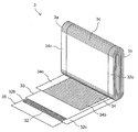
- FIG. 5 is a perspective view showing a part of the winding group.
- FIG. 6 is a graph showing the DCR increase rate of the lithium ion secondary batteries of Example 8, Comparative Example 1 and Comparative Example 4.
- the positive electrode 34 for a lithium ion secondary battery according to the first embodiment shown in FIG. 1 includes a positive electrode current collector 34a and a layered structure 34b provided on the positive electrode current collector 34a.
- the positive electrode current collector 34a is formed of an arbitrary material that has high conductivity and does not alloy with lithium ions.
- the positive electrode current collector 34a has a plate-like (sheet-like) shape having a second surface 342 which is an opposite surface of the first surface 341 and the first surface 341, but the shape of the positive electrode current collector 34a. Is not limited to this.
- an aluminum foil can be used as the positive electrode current collector 34a.
- a layered structure 34b is provided on each of the first surface 341 and the second surface 342 of the positive electrode current collector 34a. As shown in FIG. 1, a portion 34c in which the layered structure 34b is not provided (hereinafter, referred to as a “positive electrode current collector exposed portion”) 34c is provided at one end of the positive electrode current collector 34a.
- the layered structure 34b provided on the first surface 341 of the positive electrode current collector 34a will be described. Since the same description applies to the layered structure 34b provided on the second surface 342 of the positive electrode current collector 34a, the description of the layered structure 34b provided on the second surface 342 of the positive electrode current collector 34a Is omitted.
- the layered structure 34b is composed of two layers laminated in a direction perpendicular to the first surface 341 of the positive electrode current collector 34a. Of the two layers, the layer directly formed on the first surface 341 of the positive electrode current collector 34a is called the innermost layer 52, and the layer formed on the innermost layer 52 is called the outermost layer 51.
- the outermost layer 51 has the following equation (1): Li 1 + X M A O 2 (1) (During the ceremony, X satisfies ⁇ 0.15 ⁇ X ⁇ 0.15.
- M A represents an element group including Ni, Co and Mn, Ni in all the elements constituting the M A, the proportion of Co and Mn, respectively, are a (mol%), b ( mol%), c (mol%), a, b and c are 0 ⁇ a / (B + c) ⁇ 1, 1 ⁇ b / c ⁇ 2)
- the first positive electrode active material Since ⁇ 0.15 ⁇ X ⁇ 0.15, the first positive electrode active material has high true density and high reversibility.
- the lithium ion secondary battery using the positive electrode 34 for the lithium ion secondary battery according to the first embodiment has high safety.
- the first positive electrode active material has a composition satisfying 0 ⁇ a / (b + c) ⁇ 1 and 1 ⁇ b / c, so that the discharge capacity of the lithium ion secondary battery due to charging and discharging can be increased. It is possible to suppress a decrease and an increase in DC internal resistance.
- the present inventor considers this reason as follows.
- the first positive electrode active material satisfying 0 ⁇ a / (b + c) ⁇ 1 and 1 ⁇ b / c allows the charge / discharge reaction to proceed smoothly.
- the charge / discharge reaction preferentially occurs on the surface (outer surface) of the layered structure 34b farthest from the positive electrode current collector 34a.
- the lithium-ion secondary battery can maintain the discharge capacity and DC internal resistance over many charge / discharge cycles.
- the cost of the positive electrode for the lithium ion secondary battery is reduced, and the safety of the lithium ion secondary battery is improved.
- M A is, Zr, Ti, Cr, Fe , Cu, Zn, Ge, Sn, Mg, Ag, Ta, Nb, B, P, Ca, may further comprise at least one of Sr and Ba. If M A contains Zr, it reduces the internal resistance of the lithium ion secondary battery at low temperature.
- the content of Zr may be 0.1 to 2.0 mol%, particularly 0.2 to 1.0 mol%, based on the total amount of Ni, Co and Mn.
- the ratio of elements other than Ni, Co and Mn in all the elements constituting the M A is, 10 mol% or less, in particular, may be less 3 mol%. As a result, it is possible to sufficiently suppress a decrease in the discharge capacity of the lithium ion secondary battery and an increase in the DC internal resistance due to charging and discharging.
- the outermost layer 51 may further contain a binder and a conductive agent.
- binder for example, polyvinylidene fluoride (PVdF), polytetrafluoroethylene (PTFE), polyethylene, polystyrene, polybutadiene, polyacrylonitrile, polyvinyl fluoride, propylene polyvinyl fluoride, chloroprene fluoride, butyl rubber, nitrile rubber, styrene butadiene rubber, Polysulfide rubber, nitrocellulose, cyanoethyl cellulose, various latexes, acrylic resins, or mixtures thereof can be used.
- PVdF polyvinylidene fluoride
- PTFE polytetrafluoroethylene
- polyethylene polystyrene
- polybutadiene polyacrylonitrile
- polyvinyl fluoride propylene polyvinyl fluoride
- chloroprene fluoride butyl rubber
- nitrile rubber nitrile rubber
- styrene butadiene rubber Polysul
- a carbonaceous material can be used as the conductive agent.
- the carbonaceous material may be crystalline carbon, amorphous carbon, or a mixture thereof.
- crystalline carbon include artificial graphite, natural graphite (eg, scaly graphite), or mixtures thereof.
- amorphous carbon include carbon black (eg, acetylene black, ketjen black, channel black, furnace black, lamp black, thermal black, or mixtures thereof).
- the outermost layer 51 may have a thickness of 5 ⁇ m to 50 ⁇ m. As a result, it is possible to sufficiently suppress a decrease in the discharge capacity of the lithium ion secondary battery and an increase in the DC internal resistance due to charging and discharging.
- the innermost layer 52 has the following equation (2): Li 1 + Y M B O 2 (2) (During the ceremony, Y satisfies ⁇ 0.15 ⁇ Y ⁇ 0.15.
- M B represents an element group including Ni, Co, and at least one of Mn and Al) It may contain the second positive electrode active material represented by.
- the second positive electrode active material Since ⁇ 0.15 ⁇ Y ⁇ 0.15, the second positive electrode active material has high true density and high reversibility.
- the second positive electrode active material has a high stability in high thermal stability and a high potential state. Therefore, the lithium ion secondary battery using the positive electrode 34 for the lithium ion secondary battery according to the first embodiment has high safety.
- d (mol%), e (mol%) is expressed as f (mol%) and g (mol%).
- d, e, f and g satisfy 0 ⁇ d, 0 ⁇ e, 0 ⁇ f, 0 ⁇ g and 0 ⁇ f + g. Further, d, e, f and g may satisfy 1 ⁇ d / (e + f + g) ⁇ 4.
- the discharge capacity of the lithium ion secondary battery is reduced due to charging and discharging.
- the increase in DC internal resistance can be further suppressed.
- M B is, Zr, Ti, Cr, Fe , Cu, Zn, Ge, Sn, Mg, Ag, Ta, Nb, B, P, Ca, may further comprise at least one of Sr and Ba. If M B includes Zr, it reduces the internal resistance of the lithium ion secondary battery at low temperature.
- the content of Zr may be 0.1 to 2.0 mol%, particularly 0.2 to 1.0 mol%, based on the total amount of Ni, Co, Mn and Al. Further, Ni in all the elements constituting the M B, Co, the ratio of elements other than Mn and Al, 10 mol% or less, in particular, may be less 3 mol%. As a result, the discharge capacity of the lithium ion secondary battery can be sufficiently improved.
- the innermost layer 52 may further contain a binder and a conductive agent in the same manner as the outermost layer 51.
- the layered structure 34b in the first embodiment can be formed, for example, as follows.
- the first positive electrode active material, the conductive agent and the binder are dispersed in a solvent (for example, N-methyl-2-pyrrolidone (NMP), water) to prepare a paste-like or slurry-like first composition.
- a paste-like or slurry-like second composition is prepared from the second positive electrode active material, the conductive agent and the binder.
- the second composition is applied to the first surface 341 of the positive electrode current collector 34a, dried, and if necessary, subjected to calendar treatment to form the innermost layer 52.
- the first composition is applied onto the innermost layer 52, dried and, if necessary, calendared to form the outermost layer 51.
- the layered structure 34b is formed.
- the first composition and the second composition are simultaneously applied by a slot die coating method or the like and dried to form the outermost layer 51 and the innermost layer 52. You can also do it.
- the amount of each element in the first positive electrode active material and the second positive electrode active material can be measured by the ICP (Inductive Coupled Plasma) method.
- the positive electrode 34 for a lithium ion secondary battery according to the second embodiment shown in FIG. 2 includes a positive electrode current collector 34a and a layered structure 34b formed on the positive electrode current collector 34a.
- the positive electrode current collector 34a in the positive electrode 34 for a lithium ion secondary battery according to the second embodiment is the same as the positive electrode current collector 34a in the positive electrode 34 for a lithium ion secondary battery according to the first embodiment. Therefore, the description thereof will be omitted.
- a layered structure 34b is provided on each of the first surface 341 and the second surface 342 of the positive electrode current collector 34a.
- the positive electrode current collector 34a has a positive electrode current collector exposed portion 34c in which the layered structure 34b is not provided.
- the layered structure 34b provided on the first surface 341 of the positive electrode current collector 34a will be described. Since the same description applies to the layered structure 34b provided on the second surface 342 of the positive electrode current collector 34a, the description of the layered structure 34b provided on the second surface 342 of the positive electrode current collector 34a Is omitted.
- the layered structure 34b is composed of three layers laminated in a direction perpendicular to the first surface 341 of the positive electrode current collector 34a.
- the layer directly formed on the first surface 341 of the positive electrode current collector 34a is called the innermost layer 52
- the layer formed on the innermost layer 52 is called the intermediate layer 53
- the intermediate layer 53 is called.
- the layer formed on the top is called the outermost layer 51.
- outermost layer 51 and the innermost layer 52 in the second embodiment are the same as the outermost layer 51 and the innermost layer 52 in the first embodiment, the description thereof will be omitted.
- the intermediate layer 53 has the following equation (3): Li 1 + Z M C O 2 (3) (During the ceremony, Z satisfies ⁇ 0.15 ⁇ Z ⁇ 0.15.
- M C represents Ni, Co, and the element group including at least one of Mn and Al) It may contain a third positive electrode active material represented by.
- the third positive electrode active material Since ⁇ 0.15 ⁇ Z ⁇ 0.15, the third positive electrode active material has high true density and high reversibility.
- the lithium ion secondary battery using the positive electrode 34 for the lithium ion secondary battery according to the second embodiment has high safety.
- the amount of each element in the intermediate layer 53 can be measured by the ICP method.
- the intermediate layer 53 may further contain a binder and a conductive agent in the same manner as the outermost layer 51 and the innermost layer 52.
- the intermediate layer 53 may contain the conductive agent in a weight ratio higher than the weight ratio of the conductive agent in the outermost layer 51 and the innermost layer 52, and in a weight ratio lower than the weight ratio of the binder in the outermost layer 51 and the innermost layer 52.
- a binder may be contained, and the third positive electrode active material may be contained in a weight ratio lower than the weight ratio of the first positive electrode active material in the outermost layer and the weight ratio of the second positive electrode active material in the innermost layer.
- the intermediate layer 53 containing the conductive agent in a high weight ratio can hold more electrolytic solution than the outermost layer 51 and the innermost layer 52, and the outermost layer 51 and the innermost layer 52 can be retained when the lithium ion secondary battery is discharged.
- the electrolytic solution can be supplied to the battery. Therefore, the ionic conductivity in the layered structure 34b can be improved.
- the intermediate layer 53 may have a thickness smaller than that of the outermost layer 51 and the innermost layer 52.
- the layered structure 34b in the second embodiment can be formed, for example, as follows.
- the first positive electrode active material, the conductive agent and the binder are dispersed in a solvent to prepare a paste-like or slurry-like first composition.
- a paste-like or slurry-like second composition is prepared from the second positive electrode active material, the conductive agent and the binder, and a paste-like or slurry-like third is prepared from the third positive electrode active material, the conductive agent and the binder.
- the second composition is applied to the first surface 341 of the positive electrode current collector 34a, dried, and if necessary, subjected to calendar treatment to form the innermost layer 52.
- the third composition is then applied onto the innermost layer 52, dried and, if necessary, calendared to form the intermediate layer 53. Further, the first composition is applied onto the intermediate layer 53, dried and, if necessary, calendared to form the outermost layer 51. As a result, the layered structure 34b is formed.
- the first composition, the second composition and the third composition are simultaneously applied and dried by a slot die coating method or the like. , The outermost layer 51, the innermost layer 52, and the intermediate layer 53 can also be formed.
- the layered structure 34b is provided on each of the first surface 341 and the second surface 342 of the positive electrode current collector 34a, but the first of the positive electrode current collectors 34a.
- the layered structure 34b may be provided on only one of the surface 341 and the second surface 342. That is, the layered structure 34b is provided on at least one of the first surface 341 and the second surface 342 of the positive electrode current collector 34a.
- the layered structure 34b is composed of two and three layers, respectively, but the layered structure 34b may be composed of four or more layers. That is, the layered structure 34b is the outermost layer 51, which is the layer farthest from the first surface 341 of the positive electrode current collector 34a in the layered structure 34b, and the first positive electrode current collector 34a in the layered structure 34b. At least the innermost layer 52, which is the layer closest to the surface 341, may be included, and at least one intermediate layer 53 may be further included between the outermost layer 51 and the innermost layer 52.
- the positive electrode for a lithium ion secondary battery according to the above embodiment can be applied to any lithium ion secondary battery.
- an example of a lithium ion secondary battery using the positive electrode for the lithium ion secondary battery according to the above embodiment will be described.
- the lithium ion secondary battery 100 shown in FIGS. 3 and 4 is a square battery. Further, the lithium ion secondary battery 100 includes a battery can 1 and a battery lid 6.
- the battery can 1 has a side surface including a rectangular bottom surface 1d, a pair of opposing wide side surfaces 1b having a relatively large area rising from the bottom surface 1d, and a pair of opposing narrow side surfaces 1c having a relatively small area, and a wide surface. It has an opening 1a that is open upward at the upper ends of the side surface 1b and the narrow side surface 1c.
- the upper direction means the Z direction in FIGS. 3 and 4.
- the opening 1a of the battery can 1 is sealed by the battery lid 6.
- the battery lid 6 has a substantially rectangular flat plate shape, and is welded so as to close the opening 1a of the battery can 1 to seal the battery can 1.
- the battery lid 6 is integrally provided with a gas discharge valve 10.
- the gas discharge valve 10 When the pressure inside the battery can 1 rises, the gas discharge valve 10 is cleaved, gas is discharged from the inside of the battery can 1, and the pressure inside the battery can 1 decreases. As a result, the safety of the lithium ion secondary battery 100 is ensured.
- the battery lid 6 is provided with a liquid injection port 9 for injecting an electrolytic solution into the battery can 1.
- the liquid injection port 9 is sealed by the liquid injection plug 11 after the electrolytic solution is injected into the battery can 1.
- the liquid injection plug 11 is joined to the battery lid 6 by laser welding to seal the liquid injection port 9, and seals the lithium ion secondary battery 100.
- the battery lid 6 is further provided with a positive electrode side through hole 46 and a negative electrode side through hole 26.
- a positive electrode external terminal 14 and a negative electrode external terminal 12 are provided above the battery lid 6.
- a positive electrode current collector plate 44 and a negative electrode current collector plate 24 are provided below the battery lid 6 and inside the battery can 1.
- Examples of the material for forming the positive electrode external terminal 14 and the positive electrode current collector plate 44 include an aluminum alloy, and examples of the material for forming the negative electrode external terminal 12 and the negative electrode current collector plate 24 include a copper alloy.
- the positive electrode external terminal 14 and the negative electrode external terminal 12 each have a welded joint portion to be welded to a bus bar or the like.
- the welded joint has a rectangular parallelepiped block shape that projects upward from the battery lid 6.
- the lower surface of the welded joint faces the surface of the battery lid 6, and the upper surface of the welded joint is located at a predetermined height position and is substantially parallel to the battery lid 6.
- the positive electrode current collector plate 44 has a rectangular plate-shaped positive electrode current collector plate base 41 facing the lower surface of the battery lid 6 and a bottom surface 1d side along the wide side surface 1b of the battery can 1 from the side end of the positive electrode current collector plate base 41. It has a positive electrode side connecting end 42 extending toward.
- the negative electrode current collector plate 24 has a rectangular plate-shaped negative electrode current collector plate base 21 facing the lower surface of the battery lid 6 and a side end of the negative electrode current collector plate base 21 along the wide side surface 1b of the battery can 1. It has a negative electrode side connection end 22 extending toward the bottom surface 1d side.
- a positive electrode side opening hole 43 and a negative electrode side opening hole 23 are formed in the positive electrode current collector plate base 41 and the negative electrode current collector plate base 21, respectively.
- a positive electrode connecting portion 14a and a negative electrode connecting portion 12a are provided so as to project from the lower surfaces of the positive electrode external terminal 14 and the negative electrode external terminal 12, respectively.
- the positive electrode connecting portion 14a and the negative electrode connecting portion 12a are integrally formed with the positive electrode external terminal 14 and the negative electrode external terminal 12, respectively.
- the positive electrode connection portion 14a has a cylindrical shape that can be inserted into the positive electrode side through hole 46 of the battery lid 6 and the positive electrode side opening hole 43 of the positive electrode current collector plate base 41.
- the negative electrode connection portion 12a has a cylindrical shape that can be inserted into the negative electrode side through hole 26 of the battery lid 6 and the negative electrode side opening hole 23 of the negative electrode current collector plate base portion 21.
- the positive electrode connection portion 14a is arranged so as to pass through the positive electrode side through hole 46 of the battery lid 6 and the positive electrode side opening hole 43 of the positive electrode current collector plate base 41, and penetrates the battery lid 6 and the positive electrode current collector plate base 41.
- the tip of the positive electrode connection portion 14a is crimped, and the positive electrode external terminal 14 and the positive electrode current collector plate 44 are integrally fixed to the battery lid 6.
- the negative electrode connection portion 12a is arranged so as to pass through the negative electrode side through hole 26 of the battery lid 6 and the negative electrode side opening hole 23 of the negative electrode current collector plate base portion 21, and connects the battery lid 6 and the negative electrode current collector plate base portion 21. Penetrate.
- the tip of the negative electrode connecting portion 12a is crimped, and the negative electrode external terminal 12 and the negative electrode current collector plate 24 are integrally fixed to the battery lid 6.
- the positive electrode external terminal 14 is electrically connected to the winding group 3 described later via the positive electrode connecting portion 14a and the positive electrode current collector plate 44.
- the negative electrode external terminal 12 is electrically connected to the winding group 3 via the negative electrode connecting portion 12a and the negative electrode current collector plate 24.
- the winding group 3 is passed through the positive electrode external terminal 14, the positive electrode connection portion 14a and the positive electrode current collector plate 44, and the negative electrode external terminal 12, the negative electrode connection portion 12a and the negative electrode current collector plate 24. Electricity is supplied to the external load from.
- each of the positive electrode external terminal 14 and the negative electrode external terminal 12 and the battery lid A gasket 5 is provided between the positive electrode current collector plate 44 and the negative electrode current collector plate 24, and an insulating plate 7 is provided between each of the positive electrode current collector plate 44 and the negative electrode current collector plate 24 and the battery lid 6.
- the material for forming the insulating plate 7 and the gasket 5 include a resin material having an insulating property such as polybutylene terephthalate, polyphenylene sulfide, and perfluoroalkoxy alkane resin.
- the electrolytic solution, the winding group 3, and the insulating protective film 2 are stored in the battery can 1.
- the electrolytic solution is injected into the battery can 1 from the injection port 9.
- a non-aqueous electrolytic solution in which a lithium salt such as lithium hexafluorophosphate (LiPF 6 ) is dissolved in a carbonic acid ester-based organic solvent such as ethylene carbonate can be used.
- the winding group 3 has a negative electrode 32, a positive electrode 34, and two separators 33 and 35.
- the separator 35, the negative electrode 32, the separator 33, and the positive electrode 34 are stacked in this order and wound flat.
- the separator 35 is located on the outermost circumference of the winding group 3, and the negative electrode electrode 32 is located inside the separator 35.
- the two separators 33 and 35 electrically insulate the positive electrode 34 and the negative electrode 32.
- the winding group 3 has a pair of opposite end faces 3a and 3b perpendicular to the winding axis and a side surface 3c between the pair of end faces.
- the side surface 3c has a pair of curved portions facing each other having a semicircular cross section, and a flat surface portion continuously formed between the pair of curved portions.
- the winding group 3 is arranged in the battery can 1 so that the flat surface portion of the side surface 3c and the wide side surface 1b of the battery can 1 are substantially parallel to each other.
- the positive electrode electrode 34 As the positive electrode electrode 34, the positive electrode for a lithium ion secondary battery according to the above embodiment is used.
- the positive electrode current collector exposed portion 34c of the positive electrode current collector 34a (see FIGS. 1 and 2) is provided at or near the end surface 3a of the winding group 3.
- the positive electrode current collector exposed portion 34c faces the positive electrode side connection end 42 of the positive electrode current collector plate 44 and is electrically connected to the positive electrode current collector plate 44.
- the negative electrode electrode 32 has a negative electrode current collector and a negative electrode mixture layer 32b formed on both sides of the negative electrode current collector.
- the negative electrode current collector is formed from any material that is highly conductive and does not alloy with lithium ions. At one end of the negative electrode current collector, a portion (hereinafter referred to as “exposed portion of the negative electrode current collector”) 32c that is not covered with the negative electrode mixture layer 32 is provided.
- the negative electrode current collector exposed portion 32c is provided on or near the end surface 3b of the winding group 3.
- the negative electrode current collector exposed portion 32c faces the negative electrode side connection end 22 of the negative current collector plate 24 and is electrically connected.
- the negative electrode mixture layer 32b contains a negative electrode active material.
- the negative electrode active material is formed from any material capable of inserting and removing lithium ions. Examples of such materials include carbon materials such as natural graphite, artificial graphite, hard carbonized carbon (hard carbon), carbon easily graphitized (soft carbon), graphite coated with amorphous carbon, and as a conductive auxiliary agent.
- a mixture of carbon black eg, acetylene black, ketjen black, channel black, furnace black, lamp black, thermal black
- graphite a composite obtained by coating the mixture with amorphous carbon, graphite and difficulty. Examples thereof include a mixture with carbonized carbon, easily graphitized carbon or a metal oxide (for example, iron oxide, copper oxide), and a mixture thereof.
- the negative electrode mixture layer 32b further contains a binder.
- a binder the same material as that exemplified for the binder used in the layered structure 34b of the positive electrode electrode 34 can be used.
- the negative electrode mixture layer 32b further has a thickener. Carboxymethyl cellulose can be used as the thickener.
- the total thickness of the negative electrode mixture layer 32b (that is, the total thickness of the two negative electrode mixture layers 32b formed on both sides of the negative electrode current collector) is not limited, but is usually 50 ⁇ m to 200 ⁇ m.
- the separators 33 and 35 have a function of preventing a short circuit between the positive electrode 34 and the negative electrode 32 and a function of holding a non-aqueous electrolytic solution.
- a porous sheet made of a resin such as polyethylene (PE), polypropylene (PP), polyester, cellulose, or polyamide, or a laminated sheet thereof (for example, a three-layer structure of PP / PE / PP). Sheet) can be used.
- a layer containing an inorganic material (for example, alumina particles) and a binder may be provided on one or both sides of the separators 33 and 35.
- the shaft core may be arranged on the innermost circumference of the winding group 3.
- a resin sheet wound with a resin sheet having a higher bending rigidity than any of the positive electrode current collector, the negative electrode current collector, and the separators 33 and 35 can be used.
- the insulating protective film 2 is wound around the winding group 3.
- a sheet made of a synthetic resin such as polypropylene (PP) can be used as the insulating protective film 2.
- the insulating protective film 2 may be a single sheet or a sheet in which a plurality of sheets are laminated.
- the winding axis of the insulating protective film 2 is perpendicular to the winding axis of the winding group 3 and parallel to the flat surface portion of the side surface 3c of the winding group 3.
- Li 1.0 Ni a Co b Mn c O 2 powder as a first cathode active material was prepared Li 1.0 Ni d Co e Mn f Al g O 2 powder as the second cathode active material.
- the values of a to g in each example were determined by ICP analysis. The results are shown in Table 1. Further, acetylene black was prepared as a conductive agent, and polyvinylidene fluoride (PVdF) was prepared as a binder.
- PVdF polyvinylidene fluoride
- the first positive electrode active material, the conductive agent and the binder were mixed in a weight ratio of 90: 5: 5.
- N-Methyl-2-pyrrolidone (NMP) was added to the obtained mixture to adjust the viscosity, and a first slurry was obtained.
- the second positive electrode active material, the conductive agent and the binder were mixed in a weight ratio of 90: 5: 5, and N-methyl-2-pyrrolidone (NMP) was added to the obtained mixture to adjust the viscosity, and the viscosity was adjusted. Two slurries were obtained.
- An aluminum foil with a thickness of 15 ⁇ m was prepared as the positive electrode current collector.
- the slot die coating method is used on both sides of the positive electrode current collector so that the layer of the second slurry is formed on both sides of the positive electrode current collector and the layer of the first slurry is formed on the layer of the second slurry.
- One slurry and a second slurry were applied.
- the layer of the first slurry and the layer of the second slurry were dried and pressed.
- a positive electrode positive electrode for a lithium ion secondary battery in which a layered structure consisting of an outermost layer containing a first positive electrode active material and an innermost layer containing a second positive electrode active material is formed on both sides of a positive electrode current collector is formed. Obtained.
- Natural graphite coated with amorphous carbon was prepared as the negative electrode active material, styrene-butadiene rubber (SBR) was prepared as the binder, and carboxymethyl cellulose (CMC) was prepared as the dispersant.
- SBR styrene-butadiene rubber
- CMC carboxymethyl cellulose
- the negative electrode active material, binder and dispersant were mixed in a weight ratio of 98: 1: 1. Ion-exchanged water was added to the obtained mixture to adjust the viscosity, and a negative electrode slurry was obtained.
- a copper foil having a thickness of 10 ⁇ m was prepared as a negative electrode current collector.
- a negative electrode slurry was applied to both sides of the negative electrode current collector by a slot die coating method to form a negative electrode mixture layer. Then, the negative electrode mixture layer was dried and pressed. As a result, a negative electrode was obtained.
- the separator, the negative electrode, another separator, and the positive electrode were stacked in this order and wound.
- a winding group as shown in FIG. 5 was prepared.
- ethylene carbonate (EC) and dimethyl carbonate (DMC) were mixed at a volume ratio of 1: 2, and LiPF 6 was dissolved in the obtained mixed solution.
- a 1.0 mol / L LiPF 6 solution was obtained as a non-aqueous electrolytic solution.
- a lithium ion secondary battery as shown in FIGS. 3 and 4 was produced.
- Example 12 Li 1.0 Ni a Co b Mn c O 2 powder as a first cathode active material was prepared Li 1.0 Ni d Co e Mn f Al g O 2 powder as the second cathode active material.
- the values of a to g obtained by ICP analysis are as shown in Table 1.
- a first slurry and a second slurry were prepared in the same manner as in Examples 1 to 11.
- Li 1.0 Ni 0.6 Co 0.2 Mn 0.2 O 2 powder was prepared as the third positive electrode active material.
- the third positive electrode active material, the conductive agent and the binder were mixed in a weight ratio of 90: 5: 5.
- NMP N-Methyl-2-pyrrolidone
- a layer of the second slurry is formed on both sides of the positive electrode current collector, a layer of the third slurry is formed on the layer of the second slurry, and a layer of the first slurry is formed on the layer of the third slurry.
- the first slurry, the second slurry and the third slurry were applied to both sides of the positive electrode current collector by the slot die coating method. Then, drying and pressing were carried out in the same manner as in Examples 1 to 11.
- a layered structure consisting of an outermost layer containing the first positive electrode active material, an innermost layer containing the second positive electrode active material, and an intermediate layer containing the third positive electrode active material between the outermost layer and the innermost layer is a positive electrode collection. Positive electrode electrodes formed on both sides of the electric body were obtained.
- a lithium ion secondary battery was produced in the same manner as in Examples 1 to 11.
- Example 13 A lithium ion secondary battery was produced in the same manner as in Example 12 except that the third positive electrode active material, the conductive agent, and the binder were mixed in a weight ratio of 45:50: 5.
- Li 1.0 Ni a Co b Mn c O 2 powder as a first cathode active material was prepared Li 1.0 Ni d Co e Mn f Al g O 2 powder as the second cathode active material.
- the values of a to g obtained by ICP analysis are as shown in Table 1. Using these first positive electrode active material and second positive electrode active material, a lithium ion secondary battery was produced in the same manner as in Examples 1 to 11.
- Comparative Example 4 Li 1.0 Ni 0.33 Co 0.33 Mn 0.33 O 2 powder and Li 1.0 Ni 0.5 Co 0.2 Mn 0.3 O 2 powder were mixed at a weight ratio of 1: 1.
- the molar ratio of Li, Ni, Co and Mn was 1.0: 0.416: 0.267: 0.317.
- This mixed powder was used as the first positive electrode active material and the second positive electrode active material. Further, acetylene black and graphite were used as the conductive agent, and PVdF was used as the binder.
- NMP N-Methyl-2-pyrrolidone
- a lithium ion secondary battery was produced in the same manner as in Examples 1 to 11.
- the values a to g in Table 1 are values obtained by analyzing the mixed powder by the ICP method as described above.
- Comparative Example 5 The same as in Examples 1 to 11 except that Li 1.0 Co 1.0 O 2 powder was used as the first positive electrode active material and Li 1.0 Ni 1.0 O 2 powder was used as the second positive electrode active material. , A lithium ion secondary battery was manufactured.
- the lithium ion secondary battery was charged from SOC 0% to SOC 50% by a constant current-constant voltage (CC-CV) method.
- the charging current during constant current charging was 1 CA.
- the lithium ion battery was discharged at a constant current of 10 CA for 10 seconds, and the voltage drop value due to the discharge was measured.
- the same constant current discharge was performed with discharge currents of 15 CA and 20 CA.
- the discharge current was plotted on the horizontal axis and the voltage drop value was plotted on the vertical axis, and the slope of the graph was defined as the initial DCR.
- FIG. 6 shows the DCR increase rate of the lithium ion secondary batteries of Example 8, Comparative Example 1 and Comparative Example 4.
- Table 2 shows the capacity retention rate and DCR increase rate of the lithium ion secondary batteries of each Example and Comparative Example after a total of 1400 hours of charge / discharge cycle.
- the lithium ion secondary batteries of Examples 1 to 13 have the same initial battery capacity as the lithium ion secondary batteries of Comparative Examples 1 to 6, but have a higher capacity retention rate than those of Comparative Examples 1 to 6. Moreover, the DCR increase rate was low.
- the first positive electrode active material has a composition satisfying 0 ⁇ a / (b + c) ⁇ 1 and 1 ⁇ b / c, so that lithium ions due to charging and discharging are obtained. It was shown that the decrease in the discharge capacity of the secondary battery and the increase in the DC internal resistance can be suppressed.
- the lithium ion secondary batteries of Examples 1, 7 to 9 and 11 had a smaller decrease in discharge capacity and an increase in DC internal resistance than the lithium ion secondary batteries of Example 10. From this, it is shown that when the second positive electrode active material satisfies 1 ⁇ d / (e + f + g) ⁇ 4, it is possible to further suppress a decrease in the discharge capacity of the lithium ion secondary battery and an increase in the DC internal resistance due to charging and discharging. It was.
Abstract
The present invention provides a positive electrode for lithium ion secondary batteries, said positive electrode suppressing both decrease in the discharge capacity due to charge and discharge and increase in the internal resistance. This positive electrode for lithium ion secondary batteries is provided with a positive electrode collector and a lamellar structure that is provided on the positive electrode collector; the outermost layer of the lamellar structure contains a first positive electrode active material that is represented by Li1 + XMAO2 (wherein X satisfies -0.15 ≤ X ≤ 0.15; MA represents an element group containing Ni, Co and Mn; and if a (mol%), b (mol%) and c (mol%) are respective ratios of Ni, Co and Mn in all elements constituting MA, a, b and c satisfy 0 < a/(b + c) < 1 and 1 ≤ b/c ≤ 2); and the innermost layer of the lamellar structure contains a second positive electrode active material that is represented by Li1 + YMBO2 (wherein Y satisfies -0.15 ≤ Y ≤ 0.15; and MB represents an element group containing Ni, Co and at least one of Mn and Al).
Description
本発明は、リチウムイオン二次電池用正極、及びそれを用いたリチウムイオン二次電池に関する。
The present invention relates to a positive electrode for a lithium ion secondary battery and a lithium ion secondary battery using the same.
自動車産業において、燃費規制及び環境規制が強化されている。これらの規制に準拠するため、電池を動力源とし二酸化炭素を排出しない電気自動車、及び水素を燃料源とする燃料電池車の技術開発が注目されている。しかしながら、電気自動車及び燃料電池車は、インフラ整備が不十分である等の様々な問題がある。そのため、内燃機関エンジンと電池の両方を動力源とし、二酸化炭素の排出量が少ないPHEV(Plug-in Hybrid Electric Vehicle)、及びHEV(Hybrid Electric Vehicle)が、燃費規制及び環境規制に対応するための有力候補となっている。
In the automobile industry, fuel efficiency regulations and environmental regulations have been tightened. In order to comply with these regulations, attention is being paid to technological development of electric vehicles that use batteries as a power source and do not emit carbon dioxide, and fuel cell vehicles that use hydrogen as a fuel source. However, electric vehicles and fuel cell vehicles have various problems such as insufficient infrastructure development. Therefore, PHEVs (Plug-in Hybrid Electric Vehicles) and HEVs (Hybrid Electric Vehicles), which use both internal combustion engine engines and batteries as power sources and emit less carbon dioxide, are required to comply with fuel efficiency regulations and environmental regulations. It is a strong candidate.
PHEV又はHEVで用いられるリチウムイオン二次電池は、長寿命を有することが要求される。特許文献1には、正極集電体にLiXCo1-YNiYOZ(0<X≦1.3、0≦Y≦1、1.8≦Z≦2.2)で表される正極材料の層が複数積層された正極を使用したリチウム電池が記載されている。特許文献1では、正極集電体に近い正極材料の層中におけるCoの原子比に比べて、正極集電体から離れた正極材料の層中におけるCoの原子比を高くすることで、充放電による放電容量の低下を抑制している。
Lithium-ion secondary batteries used in PHEVs or HEVs are required to have a long life. Patent Document 1, represented by the cathode current collector Li X Co 1-Y Ni Y O Z (0 <X ≦ 1.3,0 ≦ Y ≦ 1,1.8 ≦ Z ≦ 2.2) A lithium battery using a positive electrode in which a plurality of layers of positive electrode materials are laminated is described. In Patent Document 1, charging / discharging is performed by increasing the atomic ratio of Co in the layer of the positive electrode material away from the positive electrode current collector as compared with the atomic ratio of Co in the layer of the positive electrode material close to the positive electrode current collector. It suppresses the decrease in discharge capacity due to.
リチウムイオン二次電池が長寿命を有するためには、充放電による放電容量の低下を抑制するだけではなく、内部抵抗の上昇も抑制する必要がある。
In order for a lithium-ion secondary battery to have a long life, it is necessary not only to suppress a decrease in discharge capacity due to charging / discharging, but also to suppress an increase in internal resistance.
そこで、本発明は、リチウムイオン電池の充放電による放電容量の低下の抑制と内部抵抗の上昇の抑制の両方を達成するリチウムイオン二次電池用正極を提供することを目的とする。
Therefore, an object of the present invention is to provide a positive electrode for a lithium ion secondary battery that achieves both suppression of a decrease in discharge capacity due to charging and discharging of a lithium ion battery and suppression of an increase in internal resistance.
本発明の一態様に従えば、
正極集電体と、
正極集電体上に設けられた層状構造体と、
を備えるリチウムイオン二次電池用正極であって、
前記層状構造体が、正極集電体から最も離れた最外層、及び正極集電体に最も近い最内層を含み、
前記最外層が、下記式(1):
Li1+XMAO2 (1)
(式中、
Xは、-0.15≦X≦0.15を満たし、
MAは、Ni、Co及びMnを含む元素群を表し、
MAを構成する全元素中のNi,Co及びMnの割合が、それぞれ、a(mol%)、b(mol%)、c(mol%)であり、a、b及びcが、0<a/(b+c)<1、1≦b/c≦2を満たす)
で表される第一正極活物質を含み、
前記最内層が、下記式(2):
Li1+YMBO2 (2)
(式中、
Yは、-0.15≦Y≦0.15を満たし、
MBは、Ni、Co、並びにMn及びAlの少なくとも一方を含む元素群を表す)
で表される第二正極活物質を含む、リチウムイオン二次電池用正極が提供される。 According to one aspect of the present invention
Positive electrode current collector and
A layered structure provided on the positive electrode current collector and
A positive electrode for a lithium ion secondary battery equipped with
The layered structure includes an outermost layer farthest from the positive electrode current collector and an innermost layer closest to the positive electrode current collector.
The outermost layer is the following formula (1):
Li 1 + X M A O 2 (1)
(During the ceremony,
X satisfies −0.15 ≦ X ≦ 0.15.
M A represents an element group including Ni, Co and Mn,
Ni in all the elements constituting the M A, the proportion of Co and Mn, respectively, are a (mol%), b ( mol%), c (mol%), a, b and c are 0 <a / (B + c) <1, 1 ≦ b / c ≦ 2)
Contains the first positive electrode active material represented by
The innermost layer is the following formula (2):
Li 1 + Y M B O 2 (2)
(During the ceremony,
Y satisfies −0.15 ≦ Y ≦ 0.15.
M B represents an element group including Ni, Co, and at least one of Mn and Al)
Provided is a positive electrode for a lithium ion secondary battery containing a second positive electrode active material represented by.
本発明の別の態様に従えば、上記態様のリチウムイオン二次電池用正極を備えるリチウムイオン二次電池が提供される。
本明細書は本願の優先権の基礎となる日本国特許出願番号2019-207241号の開示内容を包含する。 According to another aspect of the present invention, there is provided a lithium ion secondary battery including the positive electrode for the lithium ion secondary battery of the above aspect.
This specification includes the disclosure of Japanese Patent Application No. 2019-207241, which is the basis of the priority of the present application.
本発明によれば、リチウムイオン電池の充放電による放電容量の低下と内部抵抗の上昇の両方が抑制されたリチウムイオン二次電池用正極が提供される。
According to the present invention, there is provided a positive electrode for a lithium ion secondary battery in which both a decrease in discharge capacity and an increase in internal resistance due to charging and discharging of the lithium ion battery are suppressed.
(1)リチウムイオン二次電池用正極
まず、図1に示す第一実施形態に係るリチウムイオン二次電池用正極34を説明する。第一実施形態に係るリチウムイオン二次電池用正極34は、正極集電体34aと、正極集電体34a上に設けられた層状構造体34bと、を備える。 (1) Positive Electrode for Lithium Ion Secondary Battery First, thepositive electrode 34 for a lithium ion secondary battery according to the first embodiment shown in FIG. 1 will be described. The positive electrode 34 for a lithium ion secondary battery according to the first embodiment includes a positive electrode current collector 34a and a layered structure 34b provided on the positive electrode current collector 34a.
まず、図1に示す第一実施形態に係るリチウムイオン二次電池用正極34を説明する。第一実施形態に係るリチウムイオン二次電池用正極34は、正極集電体34aと、正極集電体34a上に設けられた層状構造体34bと、を備える。 (1) Positive Electrode for Lithium Ion Secondary Battery First, the
正極集電体34aは、導電性が高く且つリチウムイオンと合金化しない任意の材料から形成される。図1において、正極集電体34aは、第一面341及び第一面341の反対面である第二面342を有する板状(シート状)の形状を有するが、正極集電体34aの形状はこれに限定されない。正極集電体34aとして、例えば、アルミニウム箔を用いることができる。
The positive electrode current collector 34a is formed of an arbitrary material that has high conductivity and does not alloy with lithium ions. In FIG. 1, the positive electrode current collector 34a has a plate-like (sheet-like) shape having a second surface 342 which is an opposite surface of the first surface 341 and the first surface 341, but the shape of the positive electrode current collector 34a. Is not limited to this. As the positive electrode current collector 34a, for example, an aluminum foil can be used.
正極集電体34aの第一面341及び第二面342の各々の上に層状構造体34bが設けられる。正極集電体34aの一端には、図1に示すように、層状構造体34bが設けられていない部分(以後、「正極集電体露出部」と称する)34cが設けられる。
A layered structure 34b is provided on each of the first surface 341 and the second surface 342 of the positive electrode current collector 34a. As shown in FIG. 1, a portion 34c in which the layered structure 34b is not provided (hereinafter, referred to as a “positive electrode current collector exposed portion”) 34c is provided at one end of the positive electrode current collector 34a.
以下、正極集電体34aの第一面341上に設けられた層状構造体34bを説明する。同様の説明は、正極集電体34aの第二面342上に設けられた層状構造体34bにも当てはまるため、正極集電体34aの第二面342上に設けられた層状構造体34bの説明は省略する。
Hereinafter, the layered structure 34b provided on the first surface 341 of the positive electrode current collector 34a will be described. Since the same description applies to the layered structure 34b provided on the second surface 342 of the positive electrode current collector 34a, the description of the layered structure 34b provided on the second surface 342 of the positive electrode current collector 34a Is omitted.
第一実施形態において、層状構造体34bは、正極集電体34aの第一面341に垂直な方向に積層された二つの層からなる。二つの層のうち、正極集電体34aの第一面341上に直接形成された層を最内層52と呼び、最内層52の上に形成された層を最外層51と呼ぶ。
In the first embodiment, the layered structure 34b is composed of two layers laminated in a direction perpendicular to the first surface 341 of the positive electrode current collector 34a. Of the two layers, the layer directly formed on the first surface 341 of the positive electrode current collector 34a is called the innermost layer 52, and the layer formed on the innermost layer 52 is called the outermost layer 51.
最外層51は、下記式(1):
Li1+XMAO2 (1)
(式中、
Xは、-0.15≦X≦0.15を満たし、
MAは、Ni、Co及びMnを含む元素群を表し、
MAを構成する全元素中のNi、Co及びMnの割合が、それぞれ、a(mol%)、b(mol%)、c(mol%)であり、a、b及びcが、0<a/(b+c)<1、1≦b/c≦2を満たす)
で表される第一正極活物質を含む。 Theoutermost layer 51 has the following equation (1):
Li 1 + X M A O 2 (1)
(During the ceremony,
X satisfies −0.15 ≦ X ≦ 0.15.
M A represents an element group including Ni, Co and Mn,
Ni in all the elements constituting the M A, the proportion of Co and Mn, respectively, are a (mol%), b ( mol%), c (mol%), a, b and c are 0 <a / (B + c) <1, 1 ≦ b / c ≦ 2)
Contains the first positive electrode active material represented by.
Li1+XMAO2 (1)
(式中、
Xは、-0.15≦X≦0.15を満たし、
MAは、Ni、Co及びMnを含む元素群を表し、
MAを構成する全元素中のNi、Co及びMnの割合が、それぞれ、a(mol%)、b(mol%)、c(mol%)であり、a、b及びcが、0<a/(b+c)<1、1≦b/c≦2を満たす)
で表される第一正極活物質を含む。 The
Li 1 + X M A O 2 (1)
(During the ceremony,
X satisfies −0.15 ≦ X ≦ 0.15.
M A represents an element group including Ni, Co and Mn,
Ni in all the elements constituting the M A, the proportion of Co and Mn, respectively, are a (mol%), b ( mol%), c (mol%), a, b and c are 0 <a / (B + c) <1, 1 ≦ b / c ≦ 2)
Contains the first positive electrode active material represented by.
-0.15≦X≦0.15であることにより、第一正極活物質は、高い真密度及び高い可逆性を有する。
Since −0.15 ≦ X ≦ 0.15, the first positive electrode active material has high true density and high reversibility.
MAが、Ni及びCoに加えて、Mnを含むことにより、第一正極活物質は、高い熱安定性及び高電位状態における高い安定性を有する。そのため、第一実施形態に係るリチウムイオン二次電池用正極34を用いたリチウムイオン二次電池は、高い安全性を有する。
M A is, in addition to Ni and Co, by including Mn, the first positive electrode active material has a high stability in high thermal stability and a high potential state. Therefore, the lithium ion secondary battery using the positive electrode 34 for the lithium ion secondary battery according to the first embodiment has high safety.
後述する実施例で示すように、第一正極活物質が0<a/(b+c)<1且つ1≦b/cを満たす組成を有することにより、充放電によるリチウムイオン二次電池の放電容量の低下及び直流内部抵抗の上昇を抑制できる。この理由を、本発明者は以下のように考えている。0<a/(b+c)<1且つ1≦b/cを満たす第一正極活物質は、充放電反応を円滑に進行させる。充放電反応は、層状構造体34bの正極集電体34aから最も離れた表面(外表面)で優先的に起こる。そのため、上記の組成を有する第一正極活物質が、正極集電体34aから最も離れた最外層51に含まれることにより、より効果的に、充放電反応を円滑に進行させることができる。その結果、リチウムイオン二次電池は、多くの充放電サイクルにわたって放電容量及び直流内部抵抗を維持できる。
As shown in Examples described later, the first positive electrode active material has a composition satisfying 0 <a / (b + c) <1 and 1 ≦ b / c, so that the discharge capacity of the lithium ion secondary battery due to charging and discharging can be increased. It is possible to suppress a decrease and an increase in DC internal resistance. The present inventor considers this reason as follows. The first positive electrode active material satisfying 0 <a / (b + c) <1 and 1 ≦ b / c allows the charge / discharge reaction to proceed smoothly. The charge / discharge reaction preferentially occurs on the surface (outer surface) of the layered structure 34b farthest from the positive electrode current collector 34a. Therefore, when the first positive electrode active material having the above composition is contained in the outermost layer 51 farthest from the positive electrode current collector 34a, the charge / discharge reaction can proceed more effectively and smoothly. As a result, the lithium-ion secondary battery can maintain the discharge capacity and DC internal resistance over many charge / discharge cycles.
第一正極活物質がb/c≦2を満たす組成を有することにより、リチウムイオン二次電池用正極のコストが低減するとともに、リチウムイオン二次電池の安全性が向上する。
By having the composition of the first positive electrode active material satisfying b / c ≦ 2, the cost of the positive electrode for the lithium ion secondary battery is reduced, and the safety of the lithium ion secondary battery is improved.
MAは、Zr、Ti、Cr、Fe、Cu、Zn、Ge、Sn、Mg、Ag、Ta、Nb、B、P、Ca、Sr及びBaの少なくともいずれか一つをさらに含んでもよい。MAがZrを含む場合、低温時のリチウムイオン二次電池の内部抵抗が低減する。Zrの含有量は、Ni、Co及びMnの総量に対して、0.1~2.0mol%、特に0.2~1.0mol%であってよい。また、MAを構成する全元素中のNi、Co及びMn以外の元素の割合は、10mol%以下、特に、3mol%以下であってよい。それにより、充放電によるリチウムイオン二次電池の放電容量の低下及び直流内部抵抗の上昇を十分に抑制できる。
M A is, Zr, Ti, Cr, Fe , Cu, Zn, Ge, Sn, Mg, Ag, Ta, Nb, B, P, Ca, may further comprise at least one of Sr and Ba. If M A contains Zr, it reduces the internal resistance of the lithium ion secondary battery at low temperature. The content of Zr may be 0.1 to 2.0 mol%, particularly 0.2 to 1.0 mol%, based on the total amount of Ni, Co and Mn. The ratio of elements other than Ni, Co and Mn in all the elements constituting the M A is, 10 mol% or less, in particular, may be less 3 mol%. As a result, it is possible to sufficiently suppress a decrease in the discharge capacity of the lithium ion secondary battery and an increase in the DC internal resistance due to charging and discharging.
最外層51は、バインダー及び導電剤をさらに含んでよい。
The outermost layer 51 may further contain a binder and a conductive agent.
バインダーとして、例えば、ポリフッ化ビニリデン(PVdF)、ポリテトラフルオロエチレン(PTFE)、ポリエチレン、ポリスチレン、ポリブタジエン、ポリアクリロニトリル、ポリフッ化ビニル、ポリフッ化プロピレン、ポリフッ化クロロプレン、ブチルゴム、ニトリルゴム、スチレンブタジエンゴム、多硫化ゴム、ニトロセルロース、シアノエチルセルロース、各種ラテックス、アクリル系樹脂、又はこれらの混合物を用いることができる。
As a binder, for example, polyvinylidene fluoride (PVdF), polytetrafluoroethylene (PTFE), polyethylene, polystyrene, polybutadiene, polyacrylonitrile, polyvinyl fluoride, propylene polyvinyl fluoride, chloroprene fluoride, butyl rubber, nitrile rubber, styrene butadiene rubber, Polysulfide rubber, nitrocellulose, cyanoethyl cellulose, various latexes, acrylic resins, or mixtures thereof can be used.
導電剤として、炭素質材料を用いることができる。炭素質材料は、結晶性炭素、無定形炭素、又はこれらの混合物であってよい。結晶性炭素の例として、人造黒鉛、天然黒鉛(例えば鱗片状黒鉛)、又はこれらの混合物が挙げられる。無定形炭素の例として、カーボンブラック(例えばアセチレンブラック、ケッチェンブラック、チャンネルブラック、ファーネスブラック、ランプブラック、サーマルブラック、又はこれらの混合物)が挙げられる。
A carbonaceous material can be used as the conductive agent. The carbonaceous material may be crystalline carbon, amorphous carbon, or a mixture thereof. Examples of crystalline carbon include artificial graphite, natural graphite (eg, scaly graphite), or mixtures thereof. Examples of amorphous carbon include carbon black (eg, acetylene black, ketjen black, channel black, furnace black, lamp black, thermal black, or mixtures thereof).
最外層51は、5μm~50μmの厚さを有してよい。それにより、充放電によるリチウムイオン二次電池の放電容量の低下及び直流内部抵抗の上昇を十分に抑制できる。
The outermost layer 51 may have a thickness of 5 μm to 50 μm. As a result, it is possible to sufficiently suppress a decrease in the discharge capacity of the lithium ion secondary battery and an increase in the DC internal resistance due to charging and discharging.
最内層52は、下記式(2):
Li1+YMBO2 (2)
(式中、
Yは、-0.15≦Y≦0.15を満たし、
MBは、Ni、Co、並びにMn及びAlの少なくとも一方を含む元素群を表す)
で表される第二正極活物質を含んでよい。 Theinnermost layer 52 has the following equation (2):
Li 1 + Y M B O 2 (2)
(During the ceremony,
Y satisfies −0.15 ≦ Y ≦ 0.15.
M B represents an element group including Ni, Co, and at least one of Mn and Al)
It may contain the second positive electrode active material represented by.
Li1+YMBO2 (2)
(式中、
Yは、-0.15≦Y≦0.15を満たし、
MBは、Ni、Co、並びにMn及びAlの少なくとも一方を含む元素群を表す)
で表される第二正極活物質を含んでよい。 The
Li 1 + Y M B O 2 (2)
(During the ceremony,
Y satisfies −0.15 ≦ Y ≦ 0.15.
M B represents an element group including Ni, Co, and at least one of Mn and Al)
It may contain the second positive electrode active material represented by.
-0.15≦Y≦0.15であることにより、第二正極活物質は、高い真密度及び高い可逆性を有する。
Since −0.15 ≦ Y ≦ 0.15, the second positive electrode active material has high true density and high reversibility.
MBが、Ni及びCoに加えて、Mn及びAlの少なくとも一方を含むことにより、第二正極活物質は、高い熱安定性及び高電位状態における高い安定性を有する。そのため、第一実施形態に係るリチウムイオン二次電池用正極34を用いたリチウムイオン二次電池は、高い安全性を有する。
M B, in addition to Ni and Co, by including at least one of Mn and Al, the second positive electrode active material has a high stability in high thermal stability and a high potential state. Therefore, the lithium ion secondary battery using the positive electrode 34 for the lithium ion secondary battery according to the first embodiment has high safety.
MBを構成する全元素中のNi、Co、Mn及びAlの割合は、それぞれ、d(mol%)、e(mol%)、f(mol%)及びg(mol%)と表される。d、e、f及びgは、0<d、0<e、0≦f、0≦g、0<f+gを満たす。さらに、d、e、f及びgは、1≦d/(e+f+g)≦4を満たしてよい。層状構造体34bの外表面から最も離れた最内層52が1≦d/(e+f+g)≦4を満たす第二正極活物質を含むことで、充放電によるリチウムイオン二次電池の放電容量の低下及び直流内部抵抗の上昇を一層抑制できる。
Ni in all the elements constituting the M B, Co, the ratio of Mn and Al, respectively, d (mol%), e (mol%), is expressed as f (mol%) and g (mol%). d, e, f and g satisfy 0 <d, 0 <e, 0 ≦ f, 0 ≦ g and 0 <f + g. Further, d, e, f and g may satisfy 1 ≦ d / (e + f + g) ≦ 4. By containing the second positive electrode active material in which the innermost layer 52 farthest from the outer surface of the layered structure 34b satisfies 1 ≦ d / (e + f + g) ≦ 4, the discharge capacity of the lithium ion secondary battery is reduced due to charging and discharging. The increase in DC internal resistance can be further suppressed.
MBは、Zr、Ti、Cr、Fe、Cu、Zn、Ge、Sn、Mg、Ag、Ta、Nb、B、P、Ca、Sr及びBaの少なくともいずれか一つをさらに含んでもよい。MBがZrを含む場合、低温時のリチウムイオン二次電池の内部抵抗が低減する。Zrの含有量は、Ni、Co、Mn及びAlの総量に対して、0.1~2.0mol%、特に0.2~1.0mol%であってよい。また、MBを構成する全元素中のNi、Co、Mn及びAl以外の元素の割合は、10mol%以下、特に、3mol%以下であってよい。それにより、リチウムイオン二次電池の放電容量の十分な向上が可能となる。
M B is, Zr, Ti, Cr, Fe , Cu, Zn, Ge, Sn, Mg, Ag, Ta, Nb, B, P, Ca, may further comprise at least one of Sr and Ba. If M B includes Zr, it reduces the internal resistance of the lithium ion secondary battery at low temperature. The content of Zr may be 0.1 to 2.0 mol%, particularly 0.2 to 1.0 mol%, based on the total amount of Ni, Co, Mn and Al. Further, Ni in all the elements constituting the M B, Co, the ratio of elements other than Mn and Al, 10 mol% or less, in particular, may be less 3 mol%. As a result, the discharge capacity of the lithium ion secondary battery can be sufficiently improved.
最内層52は、最外層51と同様に、バインダー及び導電剤をさらに含んでよい。
The innermost layer 52 may further contain a binder and a conductive agent in the same manner as the outermost layer 51.
第一実施形態における層状構造体34bは、例えば以下のようにして形成することができる。第一正極活物質、導電剤及びバインダーを、溶媒(例えばN-メチル-2-ピロリドン(NMP)、水)中に分散させて、ペースト状又はスラリー状の第一組成物を調製する。同様にして、第二正極活物質、導電剤及びバインダーから、ペースト状又はスラリー状の第二組成物を調製する。第二組成物を、正極集電体34aの第一面341に塗布し、乾燥させ、必要に応じてカレンダー処理を施して、最内層52を形成する。次に、第一組成物を最内層52の上に塗布し、乾燥させ、必要に応じてカレンダー処理を施して、最外層51を形成する。それにより、層状構造体34bが形成される。第二組成物及び第一組成物を順に塗布及び乾燥する代わりに、第一組成物及び第二組成物をスロットダイコート法等により同時に塗布し、乾燥させて、最外層51及び最内層52を形成することもできる。
The layered structure 34b in the first embodiment can be formed, for example, as follows. The first positive electrode active material, the conductive agent and the binder are dispersed in a solvent (for example, N-methyl-2-pyrrolidone (NMP), water) to prepare a paste-like or slurry-like first composition. Similarly, a paste-like or slurry-like second composition is prepared from the second positive electrode active material, the conductive agent and the binder. The second composition is applied to the first surface 341 of the positive electrode current collector 34a, dried, and if necessary, subjected to calendar treatment to form the innermost layer 52. Next, the first composition is applied onto the innermost layer 52, dried and, if necessary, calendared to form the outermost layer 51. As a result, the layered structure 34b is formed. Instead of applying and drying the second composition and the first composition in order, the first composition and the second composition are simultaneously applied by a slot die coating method or the like and dried to form the outermost layer 51 and the innermost layer 52. You can also do it.
第一正極活物質及び第二正極活物質中の各元素の量は、ICP(Inductive Coupled Plasma)法により測定することができる。
The amount of each element in the first positive electrode active material and the second positive electrode active material can be measured by the ICP (Inductive Coupled Plasma) method.
次に、図2に示す第二実施形態に係るリチウムイオン二次電池用正極34を説明する。第二実施形態に係るリチウムイオン二次電池用正極34は、正極集電体34aと、正極集電体34a上に形成された層状構造体34bとを備える。
Next, the positive electrode 34 for a lithium ion secondary battery according to the second embodiment shown in FIG. 2 will be described. The positive electrode 34 for a lithium ion secondary battery according to the second embodiment includes a positive electrode current collector 34a and a layered structure 34b formed on the positive electrode current collector 34a.
第二実施形態に係るリチウムイオン二次電池用正極34中の正極集電体34aは、第一実施形態に係るリチウムイオン二次電池用正極34中の正極集電体34aと同様のものであるため、説明を省略する。
The positive electrode current collector 34a in the positive electrode 34 for a lithium ion secondary battery according to the second embodiment is the same as the positive electrode current collector 34a in the positive electrode 34 for a lithium ion secondary battery according to the first embodiment. Therefore, the description thereof will be omitted.
正極集電体34aの第一面341及び第二面342の各々の上に層状構造体34bが設けられる。正極集電体34aは、層状構造体34bが設けられていない正極集電体露出部34cを有する。
A layered structure 34b is provided on each of the first surface 341 and the second surface 342 of the positive electrode current collector 34a. The positive electrode current collector 34a has a positive electrode current collector exposed portion 34c in which the layered structure 34b is not provided.
以下、正極集電体34aの第一面341上に設けられた層状構造体34bを説明する。同様の説明は、正極集電体34aの第二面342上に設けられた層状構造体34bにも当てはまるため、正極集電体34aの第二面342上に設けられた層状構造体34bの説明は省略する。
Hereinafter, the layered structure 34b provided on the first surface 341 of the positive electrode current collector 34a will be described. Since the same description applies to the layered structure 34b provided on the second surface 342 of the positive electrode current collector 34a, the description of the layered structure 34b provided on the second surface 342 of the positive electrode current collector 34a Is omitted.
第二実施形態において、層状構造体34bは、正極集電体34aの第一面341に垂直な方向に積層された三つの層からなる。三つの層のうち、正極集電体34aの第一面341上に直接形成された層を最内層52と呼び、最内層52の上に形成された層を中間層53と呼び、中間層53の上に形成された層を最外層51と呼ぶ。
In the second embodiment, the layered structure 34b is composed of three layers laminated in a direction perpendicular to the first surface 341 of the positive electrode current collector 34a. Of the three layers, the layer directly formed on the first surface 341 of the positive electrode current collector 34a is called the innermost layer 52, the layer formed on the innermost layer 52 is called the intermediate layer 53, and the intermediate layer 53 is called. The layer formed on the top is called the outermost layer 51.
第二実施形態における最外層51及び最内層52は、第一実施形態における最外層51及び最内層52と同様のものであるため、説明を省略する。
Since the outermost layer 51 and the innermost layer 52 in the second embodiment are the same as the outermost layer 51 and the innermost layer 52 in the first embodiment, the description thereof will be omitted.
中間層53は、下記式(3):
Li1+ZMCO2 (3)
(式中、
Zは、-0.15≦Z≦0.15を満たし、
MCは、Ni、Co、並びにMn及びAlの少なくとも一方を含む元素群を表す)
で表される第三正極活物質を含んでよい。 Theintermediate layer 53 has the following equation (3):
Li 1 + Z M C O 2 (3)
(During the ceremony,
Z satisfies −0.15 ≦ Z ≦ 0.15.
M C represents Ni, Co, and the element group including at least one of Mn and Al)
It may contain a third positive electrode active material represented by.
Li1+ZMCO2 (3)
(式中、
Zは、-0.15≦Z≦0.15を満たし、
MCは、Ni、Co、並びにMn及びAlの少なくとも一方を含む元素群を表す)
で表される第三正極活物質を含んでよい。 The
Li 1 + Z M C O 2 (3)
(During the ceremony,
Z satisfies −0.15 ≦ Z ≦ 0.15.
M C represents Ni, Co, and the element group including at least one of Mn and Al)
It may contain a third positive electrode active material represented by.
-0.15≦Z≦0.15であることにより、第三正極活物質は、高い真密度及び高い可逆性を有する。
Since −0.15 ≦ Z ≦ 0.15, the third positive electrode active material has high true density and high reversibility.
MCが、Ni及びCoに加えて、Mn及びAlの少なくとも一方を含むことにより、第三正極活物質は、高い熱安定性及び高電位状態における高い安定性を有する。そのため、第二実施形態に係るリチウムイオン二次電池用正極34を用いたリチウムイオン二次電池は、高い安全性を有する。
M C, in addition to Ni and Co, by including at least one of Mn and Al, the third cathode active material, has a high stability in high thermal stability and a high potential state. Therefore, the lithium ion secondary battery using the positive electrode 34 for the lithium ion secondary battery according to the second embodiment has high safety.
中間層53の各元素の量は、ICP法により測定することができる。
The amount of each element in the intermediate layer 53 can be measured by the ICP method.
中間層53は、最外層51、最内層52と同様に、バインダー及び導電剤をさらに含んでよい。
The intermediate layer 53 may further contain a binder and a conductive agent in the same manner as the outermost layer 51 and the innermost layer 52.
中間層53は、最外層51及び最内層52における導電剤の重量割合よりも高い重量割合で導電剤を含有してよく、最外層51及び最内層52におけるバインダーの重量割合よりも低い重量割合でバインダーを含有してよく、前記最外層における第一正極活物質の重量割合及び前記最内層における第二正極活物質の重量割合よりも低い重量割合で第三正極活物質を含有してよい。それにより、層状構造体34bにおける電子伝導性が向上する。また、高い重量割合で導電剤を含む中間層53は、最外層51及び最内層52よりも多くの電解液を保持することができ、リチウムイオン二次電池の放電時に最外層51及び最内層52へ電解液を供給することができる。そのため、層状構造体34bにおけるイオン伝導性を向上させることができる。なお、この場合、中間層53は、最外層51及び最内層52よりも小さい厚みを有してよい。
The intermediate layer 53 may contain the conductive agent in a weight ratio higher than the weight ratio of the conductive agent in the outermost layer 51 and the innermost layer 52, and in a weight ratio lower than the weight ratio of the binder in the outermost layer 51 and the innermost layer 52. A binder may be contained, and the third positive electrode active material may be contained in a weight ratio lower than the weight ratio of the first positive electrode active material in the outermost layer and the weight ratio of the second positive electrode active material in the innermost layer. As a result, the electron conductivity in the layered structure 34b is improved. Further, the intermediate layer 53 containing the conductive agent in a high weight ratio can hold more electrolytic solution than the outermost layer 51 and the innermost layer 52, and the outermost layer 51 and the innermost layer 52 can be retained when the lithium ion secondary battery is discharged. The electrolytic solution can be supplied to the battery. Therefore, the ionic conductivity in the layered structure 34b can be improved. In this case, the intermediate layer 53 may have a thickness smaller than that of the outermost layer 51 and the innermost layer 52.
第二実施形態における層状構造体34bは、例えば以下のようにして形成することができる。第一正極活物質、導電剤及びバインダーを、溶媒中に分散させて、ペースト状又はスラリー状の第一組成物を調製する。同様にして、第二正極活物質、導電剤及びバインダーから、ペースト状又はスラリー状の第二組成物を調製し、第三正極活物質、導電剤及びバインダーから、ペースト状又はスラリー状の第三組成物を調製する。第二組成物を、正極集電体34aの第一面341に塗布し、乾燥させ、必要に応じてカレンダー処理を施して、最内層52を形成する。次に、第三組成物を最内層52の上に塗布し、乾燥させ、必要に応じてカレンダー処理を施して、中間層53を形成する。さらに、第一組成物を中間層53の上に塗布し、乾燥させ、必要に応じてカレンダー処理を施して、最外層51を形成する。それにより、層状構造体34bが形成される。第二組成物、第三組成物及び第一組成物を順に塗布及び乾燥する代わりに、第一組成物、第二組成物及び第三組成物をスロットダイコート法等により同時に塗布し、乾燥させて、最外層51、最内層52及び中間層53を形成することもできる。
The layered structure 34b in the second embodiment can be formed, for example, as follows. The first positive electrode active material, the conductive agent and the binder are dispersed in a solvent to prepare a paste-like or slurry-like first composition. Similarly, a paste-like or slurry-like second composition is prepared from the second positive electrode active material, the conductive agent and the binder, and a paste-like or slurry-like third is prepared from the third positive electrode active material, the conductive agent and the binder. Prepare the composition. The second composition is applied to the first surface 341 of the positive electrode current collector 34a, dried, and if necessary, subjected to calendar treatment to form the innermost layer 52. The third composition is then applied onto the innermost layer 52, dried and, if necessary, calendared to form the intermediate layer 53. Further, the first composition is applied onto the intermediate layer 53, dried and, if necessary, calendared to form the outermost layer 51. As a result, the layered structure 34b is formed. Instead of applying and drying the second composition, the third composition and the first composition in order, the first composition, the second composition and the third composition are simultaneously applied and dried by a slot die coating method or the like. , The outermost layer 51, the innermost layer 52, and the intermediate layer 53 can also be formed.
第一実施形態及び第二実施形態において、正極集電体34aの第一面341及び第二面342の各々の上に層状構造体34bが設けられているが、正極集電体34aの第一面341及び第二面342の一方のみに層状構造体34bを設けてもよい。すなわち、層状構造体34bは、正極集電体34aの第一面341及び第二面342の少なくとも一方の上に設けられる。
In the first embodiment and the second embodiment, the layered structure 34b is provided on each of the first surface 341 and the second surface 342 of the positive electrode current collector 34a, but the first of the positive electrode current collectors 34a. The layered structure 34b may be provided on only one of the surface 341 and the second surface 342. That is, the layered structure 34b is provided on at least one of the first surface 341 and the second surface 342 of the positive electrode current collector 34a.
第一実施形態及び第二実施形態において層状構造体34bはそれぞれ二つ及び三つの層からなるが、層状構造体34bは四つ以上の層からなってもよい。すなわち、層状構造体34bは、層状構造体34b中で正極集電体34aの第一面341から最も離れた層である最外層51と、層状構造体34b中で正極集電体34aの第一面341に最も近い層である最内層52とを少なくとも含み、また、最外層51と最内層52の間に少なくとも一つの中間層53をさらに含んでもよい。
In the first embodiment and the second embodiment, the layered structure 34b is composed of two and three layers, respectively, but the layered structure 34b may be composed of four or more layers. That is, the layered structure 34b is the outermost layer 51, which is the layer farthest from the first surface 341 of the positive electrode current collector 34a in the layered structure 34b, and the first positive electrode current collector 34a in the layered structure 34b. At least the innermost layer 52, which is the layer closest to the surface 341, may be included, and at least one intermediate layer 53 may be further included between the outermost layer 51 and the innermost layer 52.
(2)リチウムイオン二次電池
上記実施形態に係るリチウムイオン二次電池用正極は、任意のリチウムイオン二次電池に適用可能である。以下、上記実施形態に係るリチウムイオン二次電池用正極を用いたリチウムイオン二次電池の一例を説明する。 (2) Lithium Ion Secondary Battery The positive electrode for a lithium ion secondary battery according to the above embodiment can be applied to any lithium ion secondary battery. Hereinafter, an example of a lithium ion secondary battery using the positive electrode for the lithium ion secondary battery according to the above embodiment will be described.
上記実施形態に係るリチウムイオン二次電池用正極は、任意のリチウムイオン二次電池に適用可能である。以下、上記実施形態に係るリチウムイオン二次電池用正極を用いたリチウムイオン二次電池の一例を説明する。 (2) Lithium Ion Secondary Battery The positive electrode for a lithium ion secondary battery according to the above embodiment can be applied to any lithium ion secondary battery. Hereinafter, an example of a lithium ion secondary battery using the positive electrode for the lithium ion secondary battery according to the above embodiment will be described.
図3、4に示すリチウムイオン二次電池100は、角型電池である。また、リチウムイオン二次電池100は、電池缶1及び電池蓋6を備える。電池缶1は、矩形の底面1dと、底面1dから立ち上がる相対的に面積の大きい一対の対向する幅広側面1bと相対的に面積の小さい一対の対向する幅狭側面1cとを含む側面と、幅広側面1b及び幅狭側面1cの上端で上方に向かって開放された開口部1aとを有する。なお、ここで、上方とは、図3、4中のZ方向を意味する。
The lithium ion secondary battery 100 shown in FIGS. 3 and 4 is a square battery. Further, the lithium ion secondary battery 100 includes a battery can 1 and a battery lid 6. The battery can 1 has a side surface including a rectangular bottom surface 1d, a pair of opposing wide side surfaces 1b having a relatively large area rising from the bottom surface 1d, and a pair of opposing narrow side surfaces 1c having a relatively small area, and a wide surface. It has an opening 1a that is open upward at the upper ends of the side surface 1b and the narrow side surface 1c. Here, the upper direction means the Z direction in FIGS. 3 and 4.
電池缶1の開口部1aは、電池蓋6によって封止される。電池蓋6は略矩形平板状であって、電池缶1の開口部1aを塞ぐように溶接されて電池缶1を封止する。
The opening 1a of the battery can 1 is sealed by the battery lid 6. The battery lid 6 has a substantially rectangular flat plate shape, and is welded so as to close the opening 1a of the battery can 1 to seal the battery can 1.
電池蓋6には、ガス排出弁10が一体的に設けられている。電池缶1内の圧力が上昇すると、ガス排出弁10が開裂して電池缶1の内部からガスが排出され、電池缶1内の圧力が減少する。これによって、リチウムイオン二次電池100の安全性が確保される。
The battery lid 6 is integrally provided with a gas discharge valve 10. When the pressure inside the battery can 1 rises, the gas discharge valve 10 is cleaved, gas is discharged from the inside of the battery can 1, and the pressure inside the battery can 1 decreases. As a result, the safety of the lithium ion secondary battery 100 is ensured.
電池蓋6には、電池缶1内に電解液を注入するための注液口9が穿設される。注液口9は、電解液を電池缶1内に注入した後に注液栓11によって封止される。注液栓11は、レーザ溶接により電池蓋6に接合されて注液口9を封止し、リチウムイオン二次電池100を密閉する。
The battery lid 6 is provided with a liquid injection port 9 for injecting an electrolytic solution into the battery can 1. The liquid injection port 9 is sealed by the liquid injection plug 11 after the electrolytic solution is injected into the battery can 1. The liquid injection plug 11 is joined to the battery lid 6 by laser welding to seal the liquid injection port 9, and seals the lithium ion secondary battery 100.
電池蓋6には、さらに、正極側貫通孔46及び負極側貫通孔26が穿設される。
The battery lid 6 is further provided with a positive electrode side through hole 46 and a negative electrode side through hole 26.
電池蓋6の上方に、正極外部端子14及び負極外部端子12が設けられる。電池蓋6の下方であって電池缶1の内部に、正極集電板44及び負極集電板24が設けられる。
A positive electrode external terminal 14 and a negative electrode external terminal 12 are provided above the battery lid 6. A positive electrode current collector plate 44 and a negative electrode current collector plate 24 are provided below the battery lid 6 and inside the battery can 1.
正極外部端子14及び正極集電板44の形成素材としては、例えばアルミニウム合金が挙げられ、負極外部端子12及び負極集電板24の形成素材としては、例えば銅合金が挙げられる。
Examples of the material for forming the positive electrode external terminal 14 and the positive electrode current collector plate 44 include an aluminum alloy, and examples of the material for forming the negative electrode external terminal 12 and the negative electrode current collector plate 24 include a copper alloy.
正極外部端子14、負極外部端子12は、それぞれ、バスバー等に溶接接合される溶接接合部を有する。溶接接合部は、電池蓋6から上方に突出する直方体のブロック形状を有する。溶接接合部の下面は電池蓋6の表面に対向し、溶接接合部の上面は所定高さ位置に位置し、電池蓋6と略平行である。
The positive electrode external terminal 14 and the negative electrode external terminal 12 each have a welded joint portion to be welded to a bus bar or the like. The welded joint has a rectangular parallelepiped block shape that projects upward from the battery lid 6. The lower surface of the welded joint faces the surface of the battery lid 6, and the upper surface of the welded joint is located at a predetermined height position and is substantially parallel to the battery lid 6.
正極集電板44は、電池蓋6の下面に対向する矩形板状の正極集電板基部41と、正極集電板基部41の側端から電池缶1の幅広側面1bに沿って底面1d側に向かって延出する正極側接続端部42を有する。同様に、負極集電板24は、電池蓋6の下面に対向する矩形板状の負極集電板基部21と、負極集電板基部21の側端から電池缶1の幅広側面1bに沿って底面1d側に向かって延出する負極側接続端部22を有する。正極集電板基部41及び負極集電板基部21には、正極側開口穴43及び負極側開口穴23がそれぞれ形成される。
The positive electrode current collector plate 44 has a rectangular plate-shaped positive electrode current collector plate base 41 facing the lower surface of the battery lid 6 and a bottom surface 1d side along the wide side surface 1b of the battery can 1 from the side end of the positive electrode current collector plate base 41. It has a positive electrode side connecting end 42 extending toward. Similarly, the negative electrode current collector plate 24 has a rectangular plate-shaped negative electrode current collector plate base 21 facing the lower surface of the battery lid 6 and a side end of the negative electrode current collector plate base 21 along the wide side surface 1b of the battery can 1. It has a negative electrode side connection end 22 extending toward the bottom surface 1d side. A positive electrode side opening hole 43 and a negative electrode side opening hole 23 are formed in the positive electrode current collector plate base 41 and the negative electrode current collector plate base 21, respectively.
正極外部端子14、負極外部端子12の下面からそれぞれ突出するように、正極接続部14a、負極接続部12aが設けられる。正極接続部14a及び負極接続部12aは、それぞれ、正極外部端子14及び負極外部端子12と一体に形成される。
A positive electrode connecting portion 14a and a negative electrode connecting portion 12a are provided so as to project from the lower surfaces of the positive electrode external terminal 14 and the negative electrode external terminal 12, respectively. The positive electrode connecting portion 14a and the negative electrode connecting portion 12a are integrally formed with the positive electrode external terminal 14 and the negative electrode external terminal 12, respectively.
正極接続部14aは、電池蓋6の正極側貫通孔46及び正極集電板基部41の正極側開口穴43に挿入可能な円柱形状を有する。同様に、負極接続部12aは、電池蓋6の負極側貫通孔26及び負極集電板基部21の負極側開口穴23に挿入可能な円柱形状を有する。正極接続部14aは、電池蓋6の正極側貫通孔46及び正極集電板基部41の正極側開口穴43を通るように配置されて、電池蓋6と正極集電板基部41を貫通する。正極接続部14aは、その先端がかしめられて、正極外部端子14と正極集電板44を電池蓋6に一体に固定する。同様に、負極接続部12aは、電池蓋6の負極側貫通孔26及び負極集電板基部21の負極側開口穴23を通るように配置されて、電池蓋6と負極集電板基部21を貫通する。負極接続部12aは、その先端がかしめられて、負極外部端子12と負極集電板24を電池蓋6に一体に固定する。
The positive electrode connection portion 14a has a cylindrical shape that can be inserted into the positive electrode side through hole 46 of the battery lid 6 and the positive electrode side opening hole 43 of the positive electrode current collector plate base 41. Similarly, the negative electrode connection portion 12a has a cylindrical shape that can be inserted into the negative electrode side through hole 26 of the battery lid 6 and the negative electrode side opening hole 23 of the negative electrode current collector plate base portion 21. The positive electrode connection portion 14a is arranged so as to pass through the positive electrode side through hole 46 of the battery lid 6 and the positive electrode side opening hole 43 of the positive electrode current collector plate base 41, and penetrates the battery lid 6 and the positive electrode current collector plate base 41. The tip of the positive electrode connection portion 14a is crimped, and the positive electrode external terminal 14 and the positive electrode current collector plate 44 are integrally fixed to the battery lid 6. Similarly, the negative electrode connection portion 12a is arranged so as to pass through the negative electrode side through hole 26 of the battery lid 6 and the negative electrode side opening hole 23 of the negative electrode current collector plate base portion 21, and connects the battery lid 6 and the negative electrode current collector plate base portion 21. Penetrate. The tip of the negative electrode connecting portion 12a is crimped, and the negative electrode external terminal 12 and the negative electrode current collector plate 24 are integrally fixed to the battery lid 6.
正極外部端子14は、正極接続部14a及び正極集電板44を介して、後述する捲回群3に電気的に接続される。同様に、負極外部端子12は、負極接続部12a及び負極集電板24を介して、捲回群3に電気的に接続される。リチウムイオン二次電池100の充電時には、正極外部端子14、正極接続部14a及び正極集電板44、並びに負極外部端子12、負極接続部12a及び負極集電板24を介して、外部電源から捲回群3に電気が供給される。リチウムイオン二次電池100の放電時には、正極外部端子14、正極接続部14a及び正極集電板44、並びに負極外部端子12、負極接続部12a及び負極集電板24を介して、捲回群3から外部負荷に電気が供給される。
The positive electrode external terminal 14 is electrically connected to the winding group 3 described later via the positive electrode connecting portion 14a and the positive electrode current collector plate 44. Similarly, the negative electrode external terminal 12 is electrically connected to the winding group 3 via the negative electrode connecting portion 12a and the negative electrode current collector plate 24. When charging the lithium ion secondary battery 100, the lithium ion secondary battery 100 is wound from an external power source via the positive electrode external terminal 14, the positive electrode connection portion 14a and the positive electrode current collector plate 44, and the negative electrode external terminal 12, the negative electrode connection portion 12a and the negative electrode current collector plate 24. Electricity is supplied to the times group 3. When the lithium ion secondary battery 100 is discharged, the winding group 3 is passed through the positive electrode external terminal 14, the positive electrode connection portion 14a and the positive electrode current collector plate 44, and the negative electrode external terminal 12, the negative electrode connection portion 12a and the negative electrode current collector plate 24. Electricity is supplied to the external load from.
正極集電板44、負極集電板24、正極外部端子14及び負極外部端子12を、それぞれ電池蓋6から電気的に絶縁するために、正極外部端子14及び負極外部端子12の各々と電池蓋6との間にガスケット5が設けられ、正極集電板44及び負極集電板24の各々と電池蓋6との間に絶縁板7が設けられる。絶縁板7及びガスケット5の形成素材としては、例えばポリブチレンテレフタレートやポリフェニレンサルファイド、ペルフルオロアルコキシフッ素樹脂等の絶縁性を有する樹脂材が挙げられる。
In order to electrically insulate the positive electrode current collector plate 44, the negative electrode current collector plate 24, the positive electrode external terminal 14 and the negative electrode external terminal 12 from the battery lid 6, each of the positive electrode external terminal 14 and the negative electrode external terminal 12 and the battery lid A gasket 5 is provided between the positive electrode current collector plate 44 and the negative electrode current collector plate 24, and an insulating plate 7 is provided between each of the positive electrode current collector plate 44 and the negative electrode current collector plate 24 and the battery lid 6. Examples of the material for forming the insulating plate 7 and the gasket 5 include a resin material having an insulating property such as polybutylene terephthalate, polyphenylene sulfide, and perfluoroalkoxy alkane resin.
電池缶1内には、電解液、捲回群3及び絶縁保護フィルム2が収納される。
The electrolytic solution, the winding group 3, and the insulating protective film 2 are stored in the battery can 1.
電解液は、注液口9から電池缶1内に注入される。電解液としては、例えばエチレンカーボネート等の炭酸エステル系の有機溶媒中に6フッ化リン酸リチウム(LiPF6)等のリチウム塩が溶解された非水電解液を用いることができる。
The electrolytic solution is injected into the battery can 1 from the injection port 9. As the electrolytic solution, for example, a non-aqueous electrolytic solution in which a lithium salt such as lithium hexafluorophosphate (LiPF 6 ) is dissolved in a carbonic acid ester-based organic solvent such as ethylene carbonate can be used.
図5に示すように、捲回群3は、負極電極32、正極電極34、及び二個のセパレータ33、35を有する。セパレータ35、負極電極32、セパレータ33及び正極電極34はこの順に重ねられ、扁平状に捲回される。セパレータ35が捲回群3の最外周に位置し、その内側に負極電極32が位置する。二個のセパレータ33、35は、正極電極34と負極電極32を電気的に絶縁する。
As shown in FIG. 5, the winding group 3 has a negative electrode 32, a positive electrode 34, and two separators 33 and 35. The separator 35, the negative electrode 32, the separator 33, and the positive electrode 34 are stacked in this order and wound flat. The separator 35 is located on the outermost circumference of the winding group 3, and the negative electrode electrode 32 is located inside the separator 35. The two separators 33 and 35 electrically insulate the positive electrode 34 and the negative electrode 32.
捲回群3は、捲回軸に垂直な一対の対向する端面3a、3bと、一対の端面の間の側面3cを有する。側面3cは、断面半円形状の互いに対向する一対の湾曲部と、これら一対の湾曲部の間に連続して形成される平面部とを有する。捲回群3は、側面3cの平面部と電池缶1の幅広側面1bが略平行になるように、電池缶1内に配置される。
The winding group 3 has a pair of opposite end faces 3a and 3b perpendicular to the winding axis and a side surface 3c between the pair of end faces. The side surface 3c has a pair of curved portions facing each other having a semicircular cross section, and a flat surface portion continuously formed between the pair of curved portions. The winding group 3 is arranged in the battery can 1 so that the flat surface portion of the side surface 3c and the wide side surface 1b of the battery can 1 are substantially parallel to each other.
正極電極34として、上記実施形態に係るリチウムイオン二次電池用正極が用いられる。正極集電体34a(図1、2参照)の正極集電体露出部34cは、捲回群3の端面3a及びその近傍に設けられる。正極集電体露出部34cは、正極集電板44の正極側接続端部42に対向するともに電気的に接続される。
As the positive electrode electrode 34, the positive electrode for a lithium ion secondary battery according to the above embodiment is used. The positive electrode current collector exposed portion 34c of the positive electrode current collector 34a (see FIGS. 1 and 2) is provided at or near the end surface 3a of the winding group 3. The positive electrode current collector exposed portion 34c faces the positive electrode side connection end 42 of the positive electrode current collector plate 44 and is electrically connected to the positive electrode current collector plate 44.
負極電極32は、負極集電体と、負極集電体の両面に形成された負極合剤層32bとを有する。
The negative electrode electrode 32 has a negative electrode current collector and a negative electrode mixture layer 32b formed on both sides of the negative electrode current collector.
負極集電体は、導電性が高く且つリチウムイオンと合金化しない任意の材料から形成される。負極集電体の一端には、負極合剤層32で被覆されない部分(以後、「負極集電体露出部」と称する)32cが設けられる。負極集電体露出部32cは、捲回群3の端面3b及びその近傍に設けられる。負極集電体露出部32cは、負集電板24の負極側接続端部22に対向するともに電気的に接続される。
The negative electrode current collector is formed from any material that is highly conductive and does not alloy with lithium ions. At one end of the negative electrode current collector, a portion (hereinafter referred to as “exposed portion of the negative electrode current collector”) 32c that is not covered with the negative electrode mixture layer 32 is provided. The negative electrode current collector exposed portion 32c is provided on or near the end surface 3b of the winding group 3. The negative electrode current collector exposed portion 32c faces the negative electrode side connection end 22 of the negative current collector plate 24 and is electrically connected.
負極合剤層32bは、負極活物質を含む。負極活物質は、リチウムイオンを挿入及び脱離可能な任意の材料から形成される。そのような材料の例として、天然黒鉛、人造黒鉛、難黒鉛化炭素(ハードカーボン)、易黒鉛化炭素(ソフトカーボン)等の炭素材料、非晶質炭素で被覆した黒鉛、導電助剤としてのカーボンブラック(例えば、アセチレンブラック、ケッチェンブラック、チャンネルブラック、ファーネスブラック、ランプブラック、サーマルブラック)と黒鉛との混合物、該混合物を非晶質炭素で被覆することにより得られる複合体、黒鉛と難黒鉛化炭素、易黒鉛化炭素又は金属酸化物(例えば、酸化鉄、酸化銅)との混合物、及びこれらの混合物が挙げられる。
The negative electrode mixture layer 32b contains a negative electrode active material. The negative electrode active material is formed from any material capable of inserting and removing lithium ions. Examples of such materials include carbon materials such as natural graphite, artificial graphite, hard carbonized carbon (hard carbon), carbon easily graphitized (soft carbon), graphite coated with amorphous carbon, and as a conductive auxiliary agent. A mixture of carbon black (eg, acetylene black, ketjen black, channel black, furnace black, lamp black, thermal black) and graphite, a composite obtained by coating the mixture with amorphous carbon, graphite and difficulty. Examples thereof include a mixture with carbonized carbon, easily graphitized carbon or a metal oxide (for example, iron oxide, copper oxide), and a mixture thereof.
負極合剤層32bは、さらに、バインダーを含む。バインダーとしては、正極電極34の層状構造体34bで用いるバインダーについて例示した材料と同様の材料を用いることができる。負極合剤層32bは、さらに、増粘剤を有する。増粘剤としては、カルボキシメチルセルロースを用いることができる。
The negative electrode mixture layer 32b further contains a binder. As the binder, the same material as that exemplified for the binder used in the layered structure 34b of the positive electrode electrode 34 can be used. The negative electrode mixture layer 32b further has a thickener. Carboxymethyl cellulose can be used as the thickener.
負極合剤層32bの全体の厚み(すなわち、負極集電体の両面に形成される二個の負極合剤層32bの合計厚み)は、限定されないが、通常50μm~200μmである。
The total thickness of the negative electrode mixture layer 32b (that is, the total thickness of the two negative electrode mixture layers 32b formed on both sides of the negative electrode current collector) is not limited, but is usually 50 μm to 200 μm.
セパレータ33、35は、正極電極34と負極電極32の間の短絡を防止する機能と、非水電解液を保持する機能を有する。セパレータ33、35として、例えば、ポリエチレン(PE)、ポリプロピレン(PP)、ポリエステル、セルロース、ポリアミド等の樹脂製の多孔質シート、又はこれらの積層シート(例えば、PP/PE/PPの三層構成のシート)を用いることができる。
The separators 33 and 35 have a function of preventing a short circuit between the positive electrode 34 and the negative electrode 32 and a function of holding a non-aqueous electrolytic solution. As the separators 33 and 35, for example, a porous sheet made of a resin such as polyethylene (PE), polypropylene (PP), polyester, cellulose, or polyamide, or a laminated sheet thereof (for example, a three-layer structure of PP / PE / PP). Sheet) can be used.
セパレータ33、35の一方の面又は両面に、無機材料(例えばアルミナ粒子等)及びバインダーを含む層を設けてもよい。これにより、リチウムイオン二次電池100が異常な状態で使用された場合(例えば、過充電や圧壊等でリチウムイオン二次電池の温度が160℃以上に上昇した場合)でも、セパレータ33、35の溶融が防止され、絶縁機能を保持できる。そのため、リチウムイオン二次電池100の安全性が向上する。
A layer containing an inorganic material (for example, alumina particles) and a binder may be provided on one or both sides of the separators 33 and 35. As a result, even when the lithium ion secondary battery 100 is used in an abnormal state (for example, when the temperature of the lithium ion secondary battery rises to 160 ° C. or higher due to overcharging, crushing, etc.), the separators 33 and 35 Melting is prevented and the insulating function can be maintained. Therefore, the safety of the lithium ion secondary battery 100 is improved.
必要に応じて、捲回群3の最内周に軸芯を配置してもよい。軸芯としては、正極集電体、負極集電体、セパレータ33、35のいずれよりも曲げ剛性の高い樹脂シートを捲回したものを用いることができる。
If necessary, the shaft core may be arranged on the innermost circumference of the winding group 3. As the shaft core, a resin sheet wound with a resin sheet having a higher bending rigidity than any of the positive electrode current collector, the negative electrode current collector, and the separators 33 and 35 can be used.
捲回群3の周囲には、絶縁保護フィルム2が捲回される。絶縁保護フィルム2として、例えばポリプロピレン(PP)等の合成樹脂製のシートを用いることができる。絶縁保護フィルム2は、一枚のシートであってよいし、複数枚のシートを積層したシートであってもよい。絶縁保護フィルム2の捲回軸は、捲回群3の捲回軸に垂直、且つ、捲回群3の側面3cの平面部に平行である。
The insulating protective film 2 is wound around the winding group 3. As the insulating protective film 2, a sheet made of a synthetic resin such as polypropylene (PP) can be used. The insulating protective film 2 may be a single sheet or a sheet in which a plurality of sheets are laminated. The winding axis of the insulating protective film 2 is perpendicular to the winding axis of the winding group 3 and parallel to the flat surface portion of the side surface 3c of the winding group 3.
以上、本発明の実施形態について詳述したが、本発明は、上記実施形態に限定されるものではなく、特許請求の範囲に記載された本発明の精神を逸脱しない範囲で、種々の設計変更を行うことができる。
Although the embodiments of the present invention have been described in detail above, the present invention is not limited to the above embodiments, and various design changes are made without departing from the spirit of the present invention described in the claims. It can be performed.
以下、実施例により本発明を具体的に説明するが、本発明はこれらの実施例に限定されるものではない。
Hereinafter, the present invention will be specifically described with reference to Examples, but the present invention is not limited to these Examples.
実施例1~11
第一正極活物質としてLi1.0NiaCobMncO2粉末、第二正極活物質としてLi1.0NidCoeMnfAlgO2粉末を用意した。各実施例におけるa~gの値をICP分析により求めた。結果を表1に示す。また、導電剤としてアセチレンブラック、バインダーとしてポリフッ化ビニリデン(PVdF)を用意した。 Examples 1-11
Li 1.0 Ni a Co b Mn cO 2 powder as a first cathode active material was prepared Li 1.0 Ni d Co e Mn f Al g O 2 powder as the second cathode active material. The values of a to g in each example were determined by ICP analysis. The results are shown in Table 1. Further, acetylene black was prepared as a conductive agent, and polyvinylidene fluoride (PVdF) was prepared as a binder.
第一正極活物質としてLi1.0NiaCobMncO2粉末、第二正極活物質としてLi1.0NidCoeMnfAlgO2粉末を用意した。各実施例におけるa~gの値をICP分析により求めた。結果を表1に示す。また、導電剤としてアセチレンブラック、バインダーとしてポリフッ化ビニリデン(PVdF)を用意した。 Examples 1-11
Li 1.0 Ni a Co b Mn c
第一正極活物質、導電剤及びバインダーを90:5:5の重量比率で混合した。得られた混合物にN-メチル-2-ピロリドン(NMP)を加えて粘度を調整し、第一スラリーを得た。同様に、第二正極活物質、導電剤及びバインダーを90:5:5の重量比率で混合し、得られた混合物にN-メチル-2-ピロリドン(NMP)を加えて粘度を調整し、第二スラリーを得た。
The first positive electrode active material, the conductive agent and the binder were mixed in a weight ratio of 90: 5: 5. N-Methyl-2-pyrrolidone (NMP) was added to the obtained mixture to adjust the viscosity, and a first slurry was obtained. Similarly, the second positive electrode active material, the conductive agent and the binder were mixed in a weight ratio of 90: 5: 5, and N-methyl-2-pyrrolidone (NMP) was added to the obtained mixture to adjust the viscosity, and the viscosity was adjusted. Two slurries were obtained.
正極集電体として、厚さ15μmのアルミニウム箔を用意した。正極集電体の両面上に第二スラリーの層が形成され、該第二スラリーの層上に第一スラリーの層が形成されるように、正極集電体の両面にスロットダイコーティング法により第一スラリー及び第二スラリーを塗布した。次に、第一スラリーの層及び第二スラリーの層を乾燥及びプレスした。それにより、第一正極活物質を含む最外層及び第二正極活物質を含む最内層からなる層状構造体が正極集電体の両面に形成された正極電極(リチウムイオン二次電池用正極)を得た。
An aluminum foil with a thickness of 15 μm was prepared as the positive electrode current collector. The slot die coating method is used on both sides of the positive electrode current collector so that the layer of the second slurry is formed on both sides of the positive electrode current collector and the layer of the first slurry is formed on the layer of the second slurry. One slurry and a second slurry were applied. Next, the layer of the first slurry and the layer of the second slurry were dried and pressed. As a result, a positive electrode (positive electrode for a lithium ion secondary battery) in which a layered structure consisting of an outermost layer containing a first positive electrode active material and an innermost layer containing a second positive electrode active material is formed on both sides of a positive electrode current collector is formed. Obtained.
負極活物質として非晶質炭素被覆を施した天然黒鉛、バインダーとしてスチレンブタジエンゴム(SBR)、分散材としてカルボキシメチルセルロース(CMC)を用意した。負極活物質、バインダー及び分散剤を98:1:1の重量比率で混合した。得られた混合物にイオン交換水を加えて粘度を調整し、負極スラリーを得た。負極集電体として厚さ10μmの銅箔を用意した。負極集電体の両面に、スロットダイコーティング法により負極スラリーを塗布し、負極合剤層を形成した。そして、負極合剤層を乾燥及びプレスした。それにより、負極電極を得た。
Natural graphite coated with amorphous carbon was prepared as the negative electrode active material, styrene-butadiene rubber (SBR) was prepared as the binder, and carboxymethyl cellulose (CMC) was prepared as the dispersant. The negative electrode active material, binder and dispersant were mixed in a weight ratio of 98: 1: 1. Ion-exchanged water was added to the obtained mixture to adjust the viscosity, and a negative electrode slurry was obtained. A copper foil having a thickness of 10 μm was prepared as a negative electrode current collector. A negative electrode slurry was applied to both sides of the negative electrode current collector by a slot die coating method to form a negative electrode mixture layer. Then, the negative electrode mixture layer was dried and pressed. As a result, a negative electrode was obtained.
セパレータ、負極電極、別のセパレータ及び正極電極をこの順で重ね、捲回した。それにより、図5に示されるような捲回群を作製した。また、エチレンカーボネート(EC)とジメチルカーボネート(DMC)を1:2の体積比で混合し、得られた混合液にLiPF6を溶解した。これにより、非水電解液として1.0mol/LのLiPF6溶液を得た。捲回群と非水電解液を用いて、図3、4に示されるようなリチウムイオン二次電池を作製した。
The separator, the negative electrode, another separator, and the positive electrode were stacked in this order and wound. As a result, a winding group as shown in FIG. 5 was prepared. Further, ethylene carbonate (EC) and dimethyl carbonate (DMC) were mixed at a volume ratio of 1: 2, and LiPF 6 was dissolved in the obtained mixed solution. As a result, a 1.0 mol / L LiPF 6 solution was obtained as a non-aqueous electrolytic solution. Using the winding group and the non-aqueous electrolytic solution, a lithium ion secondary battery as shown in FIGS. 3 and 4 was produced.
実施例12
第一正極活物質としてLi1.0NiaCobMncO2粉末、第二正極活物質としてLi1.0NidCoeMnfAlgO2粉末を用意した。ICP分析により求めたa~gの値は表1に記載の通りであった。これらの第一正極活物質及び第二正極活物質を用いて、実施例1~11と同様に第一スラリー及び第二スラリーを作製した。また、第三正極活物質としてLi1.0Ni0.6Co0.2Mn0.2O2粉末を用意した。第三正極活物質、導電剤及びバインダーを90:5:5の重量比率で混合した。得られた混合物にN-メチル-2-ピロリドン(NMP)を加えて粘度を調整し、第三スラリーを得た。 Example 12
Li 1.0 Ni a Co b Mn cO 2 powder as a first cathode active material was prepared Li 1.0 Ni d Co e Mn f Al g O 2 powder as the second cathode active material. The values of a to g obtained by ICP analysis are as shown in Table 1. Using these first positive electrode active material and second positive electrode active material, a first slurry and a second slurry were prepared in the same manner as in Examples 1 to 11. Further, Li 1.0 Ni 0.6 Co 0.2 Mn 0.2 O 2 powder was prepared as the third positive electrode active material. The third positive electrode active material, the conductive agent and the binder were mixed in a weight ratio of 90: 5: 5. N-Methyl-2-pyrrolidone (NMP) was added to the obtained mixture to adjust the viscosity, and a third slurry was obtained.
第一正極活物質としてLi1.0NiaCobMncO2粉末、第二正極活物質としてLi1.0NidCoeMnfAlgO2粉末を用意した。ICP分析により求めたa~gの値は表1に記載の通りであった。これらの第一正極活物質及び第二正極活物質を用いて、実施例1~11と同様に第一スラリー及び第二スラリーを作製した。また、第三正極活物質としてLi1.0Ni0.6Co0.2Mn0.2O2粉末を用意した。第三正極活物質、導電剤及びバインダーを90:5:5の重量比率で混合した。得られた混合物にN-メチル-2-ピロリドン(NMP)を加えて粘度を調整し、第三スラリーを得た。 Example 12
Li 1.0 Ni a Co b Mn c
正極集電体の両面上に第二スラリーの層が形成され、該第二スラリーの層上に第三スラリーの層が形成され、該第三スラリーの層上に第一スラリーの層が形成されるように、正極集電体の両面にスロットダイコーティング法により第一スラリー、第二スラリー及び第三スラリーを塗布した。その後、実施例1~11と同様にして、乾燥及びプレスを行った。それにより、第一正極活物質を含む最外層、第二正極活物質を含む最内層、及び最外層と最内層の間の第三正極活物質を含む中間層とからなる層状構造体が正極集電体の両面に形成された正極電極を得た。
A layer of the second slurry is formed on both sides of the positive electrode current collector, a layer of the third slurry is formed on the layer of the second slurry, and a layer of the first slurry is formed on the layer of the third slurry. As described above, the first slurry, the second slurry and the third slurry were applied to both sides of the positive electrode current collector by the slot die coating method. Then, drying and pressing were carried out in the same manner as in Examples 1 to 11. As a result, a layered structure consisting of an outermost layer containing the first positive electrode active material, an innermost layer containing the second positive electrode active material, and an intermediate layer containing the third positive electrode active material between the outermost layer and the innermost layer is a positive electrode collection. Positive electrode electrodes formed on both sides of the electric body were obtained.
得られた正極電極を用いて、実施例1~11と同様にしてリチウムイオン二次電池を作製した。
Using the obtained positive electrode, a lithium ion secondary battery was produced in the same manner as in Examples 1 to 11.
実施例13
第三正極活物質、導電剤及びバインダーを45:50:5の重量比率で混合したこと以外は実施例12と同様にして、リチウムイオン二次電池を作製した。 Example 13
A lithium ion secondary battery was produced in the same manner as in Example 12 except that the third positive electrode active material, the conductive agent, and the binder were mixed in a weight ratio of 45:50: 5.
第三正極活物質、導電剤及びバインダーを45:50:5の重量比率で混合したこと以外は実施例12と同様にして、リチウムイオン二次電池を作製した。 Example 13
A lithium ion secondary battery was produced in the same manner as in Example 12 except that the third positive electrode active material, the conductive agent, and the binder were mixed in a weight ratio of 45:50: 5.
比較例1~3、6
第一正極活物質としてLi1.0NiaCobMncO2粉末、第二正極活物質としてLi1.0NidCoeMnfAlgO2粉末を用意した。ICP分析により求めたa~gの値は表1に記載の通りであった。これらの第一正極活物質及び第二正極活物質を用いて、実施例1~11と同様にリチウムイオン二次電池を作製した。 Comparative Examples 1 to 3, 6
Li 1.0 Ni a Co b Mn cO 2 powder as a first cathode active material was prepared Li 1.0 Ni d Co e Mn f Al g O 2 powder as the second cathode active material. The values of a to g obtained by ICP analysis are as shown in Table 1. Using these first positive electrode active material and second positive electrode active material, a lithium ion secondary battery was produced in the same manner as in Examples 1 to 11.
第一正極活物質としてLi1.0NiaCobMncO2粉末、第二正極活物質としてLi1.0NidCoeMnfAlgO2粉末を用意した。ICP分析により求めたa~gの値は表1に記載の通りであった。これらの第一正極活物質及び第二正極活物質を用いて、実施例1~11と同様にリチウムイオン二次電池を作製した。 Comparative Examples 1 to 3, 6
Li 1.0 Ni a Co b Mn c
比較例4
Li1.0Ni0.33Co0.33Mn0.33O2粉末とLi1.0Ni0.5Co0.2Mn0.3O2粉末を1:1の重量比率で混合した。得られた混合粉末の組成をICP法により分析したところ、LiとNiとCoとMnのモル比は1.0:0.416:0.267:0.317であった。この混合粉末を第一正極活物質及び第二正極活物質として用いた。また、導電剤として、アセチレンブラック及びグラファイト、バインダーとしてPVdFを用いた。 Comparative Example 4
Li 1.0 Ni 0.33 Co 0.33 Mn 0.33 O 2 powder and Li 1.0 Ni 0.5 Co 0.2 Mn 0.3 O 2 powder were mixed at a weight ratio of 1: 1. When the composition of the obtained mixed powder was analyzed by the ICP method, the molar ratio of Li, Ni, Co and Mn was 1.0: 0.416: 0.267: 0.317. This mixed powder was used as the first positive electrode active material and the second positive electrode active material. Further, acetylene black and graphite were used as the conductive agent, and PVdF was used as the binder.
混合粉末、アセチレンブラック、グラファイト、及びPVdFを90:4:3:3の重量比率で混合した。得られた混合物にN-メチル-2-ピロリドン(NMP)を加えて粘度を調整し、第一スラリー及び第二スラリーを作製した。
The mixed powder, acetylene black, graphite, and PVdF were mixed in a weight ratio of 90: 4: 3: 3. N-Methyl-2-pyrrolidone (NMP) was added to the obtained mixture to adjust the viscosity, and the first slurry and the second slurry were prepared.
得られた第一スラリー及び第二スラリーを用いて、実施例1~11と同様にリチウムイオン二次電池を作製した。なお、表1中のa~gの値は、上記のように混合粉末をICP法により分析して得た値である。
Using the obtained first slurry and second slurry, a lithium ion secondary battery was produced in the same manner as in Examples 1 to 11. The values a to g in Table 1 are values obtained by analyzing the mixed powder by the ICP method as described above.
比較例5
第一正極活物質としてLi1.0Co1.0O2粉末、第二正極活物質としてLi1.0Ni1.0O2粉末を用いたこと以外は実施例1~11と同様にして、リチウムイオン二次電池を作製した。 Comparative Example 5
The same as in Examples 1 to 11 except that Li 1.0 Co 1.0 O 2 powder was used as the first positive electrode active material and Li 1.0 Ni 1.0 O 2 powder was used as the second positive electrode active material. , A lithium ion secondary battery was manufactured.

(1)初期電池容量の測定
上記実施例及び比較例で作製したリチウムイオン二次電池を、電池電圧が4.2Vになるまで、1CAの定電流で充電し、続いて、4.2Vの定電圧で充電した。充電は合計2.5時間行った。30分間休止した後、リチウムイオン二次電池を、1CAの定電流で電池電圧が2.9Vになるまで放電し、放電容量を求めた。この放電容量を初期電池容量とした。実施例1のリチウムイオン二次電池の初期電池容量で規格化した各実施例及び比較例のリチウムイオン二次電池の初期電池容量を、表2中に示す。 (1) Measurement of initial battery capacity The lithium ion secondary batteries produced in the above Examples and Comparative Examples are charged with a constant current of 1CA until the battery voltage reaches 4.2V, and then 4.2V is constant. Charged with voltage. Charging was carried out for a total of 2.5 hours. After resting for 30 minutes, the lithium ion secondary battery was discharged at a constant current of 1CA until the battery voltage became 2.9V, and the discharge capacity was determined. This discharge capacity was used as the initial battery capacity. Table 2 shows the initial battery capacities of the lithium ion secondary batteries of Examples and Comparative Examples standardized by the initial battery capacities of the lithium ion secondary batteries of Example 1.
上記実施例及び比較例で作製したリチウムイオン二次電池を、電池電圧が4.2Vになるまで、1CAの定電流で充電し、続いて、4.2Vの定電圧で充電した。充電は合計2.5時間行った。30分間休止した後、リチウムイオン二次電池を、1CAの定電流で電池電圧が2.9Vになるまで放電し、放電容量を求めた。この放電容量を初期電池容量とした。実施例1のリチウムイオン二次電池の初期電池容量で規格化した各実施例及び比較例のリチウムイオン二次電池の初期電池容量を、表2中に示す。 (1) Measurement of initial battery capacity The lithium ion secondary batteries produced in the above Examples and Comparative Examples are charged with a constant current of 1CA until the battery voltage reaches 4.2V, and then 4.2V is constant. Charged with voltage. Charging was carried out for a total of 2.5 hours. After resting for 30 minutes, the lithium ion secondary battery was discharged at a constant current of 1CA until the battery voltage became 2.9V, and the discharge capacity was determined. This discharge capacity was used as the initial battery capacity. Table 2 shows the initial battery capacities of the lithium ion secondary batteries of Examples and Comparative Examples standardized by the initial battery capacities of the lithium ion secondary batteries of Example 1.
(2)初期直流抵抗(DCR)の測定
リチウムイオン二次電池を、電池電圧が4.2Vになるまで充電した。その後、電池容量の5%を放電した。2時間休止した後、リチウムイオン二次電池の開回路電圧(OCV)を測定した。同様にして電池容量の5%の放電とOCVの測定を繰り返し、充電率(SOC)とOCVの関係を求めた。 (2) Measurement of initial direct current resistance (DCR) The lithium ion secondary battery was charged until the battery voltage reached 4.2 V. Then, 5% of the battery capacity was discharged. After resting for 2 hours, the open circuit voltage (OCV) of the lithium ion secondary battery was measured. In the same manner, the discharge of 5% of the battery capacity and the measurement of OCV were repeated to determine the relationship between the charge rate (SOC) and OCV.
リチウムイオン二次電池を、電池電圧が4.2Vになるまで充電した。その後、電池容量の5%を放電した。2時間休止した後、リチウムイオン二次電池の開回路電圧(OCV)を測定した。同様にして電池容量の5%の放電とOCVの測定を繰り返し、充電率(SOC)とOCVの関係を求めた。 (2) Measurement of initial direct current resistance (DCR) The lithium ion secondary battery was charged until the battery voltage reached 4.2 V. Then, 5% of the battery capacity was discharged. After resting for 2 hours, the open circuit voltage (OCV) of the lithium ion secondary battery was measured. In the same manner, the discharge of 5% of the battery capacity and the measurement of OCV were repeated to determine the relationship between the charge rate (SOC) and OCV.
SOCとOCVの関係に基づき、リチウムイオン二次電池を、SOC0%からSOC50%まで、定電流-定電圧(CC-CV)方式で充電した。定電流充電中の充電電流は1CAとした。その後、リチウムイオン電池を10CAの定電流で10秒間放電し、放電による電圧降下値を測定した。さらに、同様の定電流放電を放電電流15CA及び20CAで行った。放電電流を横軸、電圧降下値を縦軸にプロットし、そのグラフの傾きを初期DCRとした。
Based on the relationship between SOC and OCV, the lithium ion secondary battery was charged from SOC 0% to SOC 50% by a constant current-constant voltage (CC-CV) method. The charging current during constant current charging was 1 CA. Then, the lithium ion battery was discharged at a constant current of 10 CA for 10 seconds, and the voltage drop value due to the discharge was measured. Further, the same constant current discharge was performed with discharge currents of 15 CA and 20 CA. The discharge current was plotted on the horizontal axis and the voltage drop value was plotted on the vertical axis, and the slope of the graph was defined as the initial DCR.
(3)充放電サイクル試験
45℃の環境温度下で、リチウムイオン二次電池を、SOC80%まで10CAの定電流で充電し、続いてSOC20%まで10CAの定電流で放電した。この充放電サイクルを200時間繰り返した。その後、リチウムイオン二次電池の電池容量及びDCRを、初期電池容量及び初期DCRと同様の方法で測定した。測定した電池容量を初期電池容量で除して容量維持率を求めた。また、測定したDCRを初期DCRで除してDCR上昇率を求めた。 (3) Charge / Discharge Cycle Test At an environmental temperature of 45 ° C., the lithium ion secondary battery was charged with a constant current of 10 CA up to 80% SOC, and then discharged with a constant current of 10 CA up to 20% SOC. This charge / discharge cycle was repeated for 200 hours. Then, the battery capacity and DCR of the lithium ion secondary battery were measured by the same method as the initial battery capacity and initial DCR. The capacity retention rate was calculated by dividing the measured battery capacity by the initial battery capacity. Further, the measured DCR was divided by the initial DCR to obtain the DCR increase rate.
45℃の環境温度下で、リチウムイオン二次電池を、SOC80%まで10CAの定電流で充電し、続いてSOC20%まで10CAの定電流で放電した。この充放電サイクルを200時間繰り返した。その後、リチウムイオン二次電池の電池容量及びDCRを、初期電池容量及び初期DCRと同様の方法で測定した。測定した電池容量を初期電池容量で除して容量維持率を求めた。また、測定したDCRを初期DCRで除してDCR上昇率を求めた。 (3) Charge / Discharge Cycle Test At an environmental temperature of 45 ° C., the lithium ion secondary battery was charged with a constant current of 10 CA up to 80% SOC, and then discharged with a constant current of 10 CA up to 20% SOC. This charge / discharge cycle was repeated for 200 hours. Then, the battery capacity and DCR of the lithium ion secondary battery were measured by the same method as the initial battery capacity and initial DCR. The capacity retention rate was calculated by dividing the measured battery capacity by the initial battery capacity. Further, the measured DCR was divided by the initial DCR to obtain the DCR increase rate.
上記の200時間の充放電と電池容量及びDCRの測定をさらに6回繰り返した。実施例8、比較例1及び比較例4のリチウムイオン二次電池のDCR上昇率を図6に示す。また、合計1400時間の充放電サイクル後の各実施例及び比較例のリチウムイオン二次電池の容量維持率とDCR上昇率を表2中に示す。
The above 200-hour charge / discharge and battery capacity and DCR measurements were repeated 6 more times. FIG. 6 shows the DCR increase rate of the lithium ion secondary batteries of Example 8, Comparative Example 1 and Comparative Example 4. Table 2 shows the capacity retention rate and DCR increase rate of the lithium ion secondary batteries of each Example and Comparative Example after a total of 1400 hours of charge / discharge cycle.

通常、リチウムイオン二次電池の初期電池容量と寿命はトレードオフの関係にある。しかし、実施例1~13のリチウムイオン二次電池は、比較例1~6のリチウムイオン二次電池と同等の初期電池容量を有しつつ、比較例1~6よりも容量維持率が高く、且つ、DCR上昇率が低かった。特に、実施例1~5と比較例6の評価結果から、第一正極活物質が0<a/(b+c)<1且つ1≦b/cを満たす組成を有することにより、充放電によるリチウムイオン二次電池の放電容量の低下及び直流内部抵抗の上昇を抑制できることが示された。また、実施例1、7~9、11のリチウムイオン二次電池は、実施例10のリチウムイオン二次電池と比べて、放電容量の低下及び直流内部抵抗の上昇がより小さかった。このことから、第二正極活物質が1≦d/(e+f+g)≦4を満たすことにより、充放電によるリチウムイオン二次電池の放電容量の低下及び直流内部抵抗の上昇を一層抑制できることが示された。
Normally, there is a trade-off between the initial battery capacity and the life of a lithium-ion secondary battery. However, the lithium ion secondary batteries of Examples 1 to 13 have the same initial battery capacity as the lithium ion secondary batteries of Comparative Examples 1 to 6, but have a higher capacity retention rate than those of Comparative Examples 1 to 6. Moreover, the DCR increase rate was low. In particular, from the evaluation results of Examples 1 to 5 and Comparative Example 6, the first positive electrode active material has a composition satisfying 0 <a / (b + c) <1 and 1 ≦ b / c, so that lithium ions due to charging and discharging are obtained. It was shown that the decrease in the discharge capacity of the secondary battery and the increase in the DC internal resistance can be suppressed. Further, the lithium ion secondary batteries of Examples 1, 7 to 9 and 11 had a smaller decrease in discharge capacity and an increase in DC internal resistance than the lithium ion secondary batteries of Example 10. From this, it is shown that when the second positive electrode active material satisfies 1 ≦ d / (e + f + g) ≦ 4, it is possible to further suppress a decrease in the discharge capacity of the lithium ion secondary battery and an increase in the DC internal resistance due to charging and discharging. It was.
34 リチウムイオン二次電池用正極(正極電極)
34a 正極集電体
34b 層状構造体
51 最外層
52 最内層
53 中間層
100 リチウムイオン二次電池
本明細書で引用した全ての刊行物、特許及び特許出願はそのまま引用により本明細書に組み入れられるものとする。 34 Positive electrode for lithium ion secondary battery (positive electrode)
34aPositive Electrode Collector 34b Layered Structure 51 Outer Layer 52 Inner Layer 53 Intermediate Layer 100 Lithium Ion Secondary Battery All publications, patents and patent applications cited herein are incorporated herein by reference in their entirety. And.
34a 正極集電体
34b 層状構造体
51 最外層
52 最内層
53 中間層
100 リチウムイオン二次電池
本明細書で引用した全ての刊行物、特許及び特許出願はそのまま引用により本明細書に組み入れられるものとする。 34 Positive electrode for lithium ion secondary battery (positive electrode)
34a
Claims (6)
- 正極集電体と、
正極集電体上に設けられた層状構造体と、
を備えるリチウムイオン二次電池用正極であって、
前記層状構造体が、正極集電体から最も離れた最外層、及び正極集電体に最も近い最内層を含み、
前記最外層が、下記式(1):
Li1+XMAO2 (1)
(式中、
Xは、-0.15≦X≦0.15を満たし、
MAは、Ni、Co及びMnを含む元素群を表し、
MAを構成する全元素中のNi,Co及びMnの割合が、それぞれ、a(mol%)、b(mol%)、c(mol%)であり、a、b及びcが、0<a/(b+c)<1、1≦b/c≦2を満たす)
で表される第一正極活物質を含み、
前記最内層が、下記式(2):
Li1+YMBO2 (2)
(式中、
Yは、-0.15≦Y≦0.15を満たし、
MBは、Ni、Co、並びにMn及びAlの少なくとも一方を含む元素群を表す)
で表される第二正極活物質を含む、リチウムイオン二次電池用正極。 Positive electrode current collector and
A layered structure provided on the positive electrode current collector and
A positive electrode for a lithium ion secondary battery equipped with
The layered structure includes an outermost layer farthest from the positive electrode current collector and an innermost layer closest to the positive electrode current collector.
The outermost layer is the following formula (1):
Li 1 + X M A O 2 (1)
(During the ceremony,
X satisfies −0.15 ≦ X ≦ 0.15.
M A represents an element group including Ni, Co and Mn,
Ni in all the elements constituting the M A, the proportion of Co and Mn, respectively, are a (mol%), b ( mol%), c (mol%), a, b and c are 0 <a / (B + c) <1, 1 ≦ b / c ≦ 2)
Contains the first positive electrode active material represented by
The innermost layer is the following formula (2):
Li 1 + Y M B O 2 (2)
(During the ceremony,
Y satisfies −0.15 ≦ Y ≦ 0.15.
M B represents an element group including Ni, Co, and at least one of Mn and Al)
A positive electrode for a lithium ion secondary battery containing a second positive electrode active material represented by. - MBを構成する全元素中のNi、Co、Mn及びAlの割合が、それぞれ、d(mol%)、e(mol%)、f(mol%)及びg(mol%)であり、d、e、f及びgが、1≦d/(e+f+g)≦4を満たす、請求項1に記載のリチウムイオン二次電池用正極。 Ni in all the elements constituting the M B, Co, the ratio of Mn and Al are each, d (mol%), e (mol%), f (mol%) and g (mol%), d, The positive electrode for a lithium ion secondary battery according to claim 1, wherein e, f and g satisfy 1 ≦ d / (e + f + g) ≦ 4.
- 前記層状構造体が、前記最外層と前記最内層の間に中間層をさらに含む、請求項1又は2に記載のリチウムイオン二次電池用正極。 The positive electrode for a lithium ion secondary battery according to claim 1 or 2, wherein the layered structure further includes an intermediate layer between the outermost layer and the innermost layer.
- 前記中間層が、第三正極活物質を含み、
前記最外層、前記最内層、及び前記中間層が、それぞれ、バインダー及び導電剤をさらに含み、
前記中間層における前記導電剤の重量割合が、前記最外層及び前記最内層における前記導電剤の重量割合よりも高く、
前記中間層における前記バインダーの重量割合が、前記最外層及び前記最内層における前記バインダーの重量割合よりも低く、
前記中間層における第三正極活物質の重量割合が、前記最外層における第一正極活物質の重量割合及び前記最内層における第二正極活物質の重量割合よりも低い、請求項3に記載のリチウムイオン二次電池用正極。 The intermediate layer contains a third positive electrode active material and contains.
The outermost layer, the innermost layer, and the intermediate layer each further contain a binder and a conductive agent, respectively.
The weight ratio of the conductive agent in the intermediate layer is higher than the weight ratio of the conductive agent in the outermost layer and the innermost layer.
The weight ratio of the binder in the intermediate layer is lower than the weight ratio of the binder in the outermost layer and the innermost layer.
The lithium according to claim 3, wherein the weight ratio of the third positive electrode active material in the intermediate layer is lower than the weight ratio of the first positive electrode active material in the outermost layer and the weight ratio of the second positive electrode active material in the innermost layer. Positive electrode for ion secondary batteries. - MAとMBの少なくとも一方が、Zr、Ti、Cr、Fe、Cu、Zn、Ge、Sn、Mg、Ag、Ta、Nb、B、P、Ca、Sr及びBaの少なくともいずれか一つをさらに含む、請求項1~4のいずれか一項に記載のリチウムイオン二次電池用正極。 At least one of M A and M B are, Zr, Ti, Cr, Fe , Cu, Zn, Ge, Sn, Mg, Ag, Ta, Nb, B, P, Ca, at least one of Sr and Ba The positive electrode for a lithium ion secondary battery according to any one of claims 1 to 4, further comprising.
- 請求項1~5のいずれか一項に記載のリチウムイオン二次電池用正極を備えるリチウムイオン二次電池。 A lithium ion secondary battery including the positive electrode for the lithium ion secondary battery according to any one of claims 1 to 5.
Priority Applications (4)
| Application Number | Priority Date | Filing Date | Title |
|---|---|---|---|
| US17/760,913 US20220352505A1 (en) | 2019-11-15 | 2020-11-12 | Positive electrode for lithium ion secondary batteries, and lithium ion secondary battery |
| CN202080064687.9A CN114402459A (en) | 2019-11-15 | 2020-11-12 | Positive electrode for lithium ion secondary battery and lithium ion secondary battery |
| EP20888111.0A EP4060759A4 (en) | 2019-11-15 | 2020-11-12 | Positive electrode for lithium ion secondary batteries, and lithium ion secondary battery |
| JP2021556156A JP7461964B2 (en) | 2019-11-15 | 2020-11-12 | Positive electrode for lithium ion secondary battery, lithium ion secondary battery and method |
Applications Claiming Priority (2)
| Application Number | Priority Date | Filing Date | Title |
|---|---|---|---|
| JP2019207241 | 2019-11-15 | ||
| JP2019-207241 | 2019-11-15 |
Publications (1)
| Publication Number | Publication Date |
|---|---|
| WO2021095818A1 true WO2021095818A1 (en) | 2021-05-20 |
Family
ID=75912721
Family Applications (1)
| Application Number | Title | Priority Date | Filing Date |
|---|---|---|---|
| PCT/JP2020/042320 WO2021095818A1 (en) | 2019-11-15 | 2020-11-12 | Positive electrode for lithium ion secondary batteries, and lithium ion secondary battery |
Country Status (5)
| Country | Link |
|---|---|
| US (1) | US20220352505A1 (en) |
| EP (1) | EP4060759A4 (en) |
| JP (1) | JP7461964B2 (en) |
| CN (1) | CN114402459A (en) |
| WO (1) | WO2021095818A1 (en) |
Cited By (1)
| Publication number | Priority date | Publication date | Assignee | Title |
|---|---|---|---|---|
| WO2024047854A1 (en) * | 2022-09-01 | 2024-03-07 | ビークルエナジージャパン株式会社 | Lithium ion secondary battery positive electrode and lithium ion secondary battery |
Citations (10)
| Publication number | Priority date | Publication date | Assignee | Title |
|---|---|---|---|---|
| JPH10255762A (en) | 1997-03-10 | 1998-09-25 | Sanyo Electric Co Ltd | Lithium battery |
| JP2014026777A (en) * | 2012-07-25 | 2014-02-06 | Toyota Motor Corp | Nonaqueous electrolyte secondary battery and method for manufacturing positive electrode for the secondary battery |
| JP2015115244A (en) * | 2013-12-13 | 2015-06-22 | 株式会社Gsユアサ | Positive electrode for lithium secondary battery, lithium secondary battery, battery module, and automobile mounting battery module |
| CN108933242A (en) * | 2018-07-10 | 2018-12-04 | 邓丽萍 | A kind of preparation method of lithium ion battery blended anode |
| JP2019029205A (en) * | 2017-07-31 | 2019-02-21 | パナソニック株式会社 | Positive electrode for nonaqueous electrolyte secondary battery, and nonaqueous electrolyte secondary battery |
| JP2019140039A (en) * | 2018-02-14 | 2019-08-22 | トヨタ自動車株式会社 | Nonaqueous electrolyte secondary battery |
| JP2019192470A (en) * | 2018-04-24 | 2019-10-31 | トヨタ自動車株式会社 | Electrode and battery using the same |
| CN110429252A (en) * | 2019-07-19 | 2019-11-08 | 宁德新能源科技有限公司 | Anode and electrochemical appliance |
| JP2019207241A (en) | 2015-11-02 | 2019-12-05 | ティーディーケイ・エレクトロニクス・アクチェンゲゼルシャフトTdk Electronics Ag | Sensor element and method for manufacturing sensor element |
| US20200006767A1 (en) * | 2018-06-28 | 2020-01-02 | Contemporary Amperex Technology Co., Limited | Positive electrode plate and lithium ion battery |
Family Cites Families (11)
| Publication number | Priority date | Publication date | Assignee | Title |
|---|---|---|---|---|
| US7691535B2 (en) | 2002-03-27 | 2010-04-06 | Gs Yuasa Corporation | Active substance of positive electrode and non-aqueous electrolyte battery containing the same |
| JP2005209496A (en) * | 2004-01-23 | 2005-08-04 | Matsushita Electric Ind Co Ltd | Nonaqueous electrolyte secondary battery |
| JP2006196247A (en) * | 2005-01-12 | 2006-07-27 | Matsushita Electric Ind Co Ltd | Negative electrode for lithium secondary battery and lithium secondary battery |
| JP5032800B2 (en) | 2005-07-14 | 2012-09-26 | パナソニック株式会社 | Positive electrode for lithium secondary battery and lithium secondary battery using the same |
| JP4972624B2 (en) * | 2008-09-30 | 2012-07-11 | 日立ビークルエナジー株式会社 | Positive electrode material for lithium secondary battery and lithium secondary battery using the same |
| KR101050438B1 (en) * | 2008-11-10 | 2011-07-19 | 주식회사 코캄 | A positive electrode active material for lithium secondary batteries having excellent safety, a method of manufacturing the same, and a lithium secondary battery comprising the same |
| KR101783445B1 (en) * | 2015-03-17 | 2017-09-29 | 주식회사 엘지화학 | Multilayer-Structured Electrode and Lithium Secondary Battery Comprising The Same |
| JP2016213057A (en) * | 2015-05-08 | 2016-12-15 | 凸版印刷株式会社 | Negative electrode for nonaqueous electrolyte secondary battery, method for manufacturing the same, and nonaqueous electrolyte secondary battery |
| CN110392947B (en) * | 2017-03-29 | 2022-11-25 | 松下知识产权经营株式会社 | Secondary battery |
| WO2018221024A1 (en) | 2017-05-31 | 2018-12-06 | パナソニックIpマネジメント株式会社 | Positive electrode for secondary battery, and secondary battery |
| JP6992162B2 (en) | 2018-03-30 | 2022-01-13 | 株式会社東芝 | Batteries and battery packs |
-
2020
- 2020-11-12 EP EP20888111.0A patent/EP4060759A4/en active Pending
- 2020-11-12 US US17/760,913 patent/US20220352505A1/en active Pending
- 2020-11-12 CN CN202080064687.9A patent/CN114402459A/en active Pending
- 2020-11-12 WO PCT/JP2020/042320 patent/WO2021095818A1/en active Search and Examination
- 2020-11-12 JP JP2021556156A patent/JP7461964B2/en active Active
Patent Citations (10)
| Publication number | Priority date | Publication date | Assignee | Title |
|---|---|---|---|---|
| JPH10255762A (en) | 1997-03-10 | 1998-09-25 | Sanyo Electric Co Ltd | Lithium battery |
| JP2014026777A (en) * | 2012-07-25 | 2014-02-06 | Toyota Motor Corp | Nonaqueous electrolyte secondary battery and method for manufacturing positive electrode for the secondary battery |
| JP2015115244A (en) * | 2013-12-13 | 2015-06-22 | 株式会社Gsユアサ | Positive electrode for lithium secondary battery, lithium secondary battery, battery module, and automobile mounting battery module |
| JP2019207241A (en) | 2015-11-02 | 2019-12-05 | ティーディーケイ・エレクトロニクス・アクチェンゲゼルシャフトTdk Electronics Ag | Sensor element and method for manufacturing sensor element |
| JP2019029205A (en) * | 2017-07-31 | 2019-02-21 | パナソニック株式会社 | Positive electrode for nonaqueous electrolyte secondary battery, and nonaqueous electrolyte secondary battery |
| JP2019140039A (en) * | 2018-02-14 | 2019-08-22 | トヨタ自動車株式会社 | Nonaqueous electrolyte secondary battery |
| JP2019192470A (en) * | 2018-04-24 | 2019-10-31 | トヨタ自動車株式会社 | Electrode and battery using the same |
| US20200006767A1 (en) * | 2018-06-28 | 2020-01-02 | Contemporary Amperex Technology Co., Limited | Positive electrode plate and lithium ion battery |
| CN108933242A (en) * | 2018-07-10 | 2018-12-04 | 邓丽萍 | A kind of preparation method of lithium ion battery blended anode |
| CN110429252A (en) * | 2019-07-19 | 2019-11-08 | 宁德新能源科技有限公司 | Anode and electrochemical appliance |
Non-Patent Citations (1)
| Title |
|---|
| See also references of EP4060759A4 |
Cited By (1)
| Publication number | Priority date | Publication date | Assignee | Title |
|---|---|---|---|---|
| WO2024047854A1 (en) * | 2022-09-01 | 2024-03-07 | ビークルエナジージャパン株式会社 | Lithium ion secondary battery positive electrode and lithium ion secondary battery |
Also Published As
| Publication number | Publication date |
|---|---|
| JP7461964B2 (en) | 2024-04-04 |
| JPWO2021095818A1 (en) | 2021-05-20 |
| EP4060759A4 (en) | 2023-12-06 |
| EP4060759A1 (en) | 2022-09-21 |
| CN114402459A (en) | 2022-04-26 |
| US20220352505A1 (en) | 2022-11-03 |
Similar Documents
| Publication | Publication Date | Title |
|---|---|---|
| JP5741936B2 (en) | Lithium ion secondary battery | |
| JP6176500B2 (en) | Secondary battery, method for producing the same, and method for producing negative electrode sheet used in the battery | |
| JP2023018128A (en) | Electrode for lithium secondary battery and lithium secondary battery | |
| JP5765574B2 (en) | Secondary battery, method for producing the same, and method for producing negative electrode sheet used in the battery | |
| WO2021095818A1 (en) | Positive electrode for lithium ion secondary batteries, and lithium ion secondary battery | |
| JP5168535B2 (en) | Lithium secondary battery and manufacturing method thereof | |
| EP3731310B1 (en) | Positive electrode for lithium ion secondary cell, and lithium ion secondary cell using same | |
| JP2000090932A (en) | Lithium secondary battery | |
| WO2022163456A1 (en) | Charging method for non-aqueous electrolyte secondary battery, charging/discharging method, and charging system for non-aqueous electrolyte secondary battery | |
| JP6735036B2 (en) | Lithium ion secondary battery | |
| WO2022185584A1 (en) | Lithium ion secondary battery and manufacturing method for negative electrode for lithium ion secondary battery | |
| WO2023021781A1 (en) | Lithium ion secondary battery | |
| WO2010067410A1 (en) | Lithium ion battery and method for manufacturing the same | |
| WO2024048611A1 (en) | Negative electrode and battery | |
| WO2024048609A1 (en) | Negative electrode and battery | |
| WO2022163578A1 (en) | Method for charging nonaqueous electrolyte secondary battery, charging/discharging method, and charging system for nonaqueous electrolyte secondary battery | |
| JP2013143262A (en) | Lithium ion secondary battery | |
| US20230318139A1 (en) | Lithium ion secondary battery and method for producing same | |
| JP6978500B2 (en) | Secondary battery | |
| CN110100345B (en) | Secondary battery | |
| JP6255502B2 (en) | Lithium ion secondary battery | |
| JP2015076289A (en) | Wound secondary battery | |
| CN116830344A (en) | Power storage element and method for using power storage element | |
| JP2010080233A (en) | Lithium secondary battery |
Legal Events
| Date | Code | Title | Description |
|---|---|---|---|
| 121 | Ep: the epo has been informed by wipo that ep was designated in this application |
Ref document number: 20888111 Country of ref document: EP Kind code of ref document: A1 |
|
| DPE2 | Request for preliminary examination filed before expiration of 19th month from priority date (pct application filed from 20040101) | ||
| ENP | Entry into the national phase |
Ref document number: 2021556156 Country of ref document: JP Kind code of ref document: A |
|
| NENP | Non-entry into the national phase |
Ref country code: DE |
|
| ENP | Entry into the national phase |
Ref document number: 2020888111 Country of ref document: EP Effective date: 20220615 |