WO2021019845A1 - 離型フィルム、フィルム積層体、これらの製造方法 - Google Patents
離型フィルム、フィルム積層体、これらの製造方法 Download PDFInfo
- Publication number
- WO2021019845A1 WO2021019845A1 PCT/JP2020/016391 JP2020016391W WO2021019845A1 WO 2021019845 A1 WO2021019845 A1 WO 2021019845A1 JP 2020016391 W JP2020016391 W JP 2020016391W WO 2021019845 A1 WO2021019845 A1 WO 2021019845A1
- Authority
- WO
- WIPO (PCT)
- Prior art keywords
- film
- release
- silicone
- fluorine
- layer
- Prior art date
Links
Images

Classifications
-
- C—CHEMISTRY; METALLURGY
- C08—ORGANIC MACROMOLECULAR COMPOUNDS; THEIR PREPARATION OR CHEMICAL WORKING-UP; COMPOSITIONS BASED THEREON
- C08J—WORKING-UP; GENERAL PROCESSES OF COMPOUNDING; AFTER-TREATMENT NOT COVERED BY SUBCLASSES C08B, C08C, C08F, C08G or C08H
- C08J7/00—Chemical treatment or coating of shaped articles made of macromolecular substances
- C08J7/04—Coating
- C08J7/0427—Coating with only one layer of a composition containing a polymer binder
-
- B—PERFORMING OPERATIONS; TRANSPORTING
- B29—WORKING OF PLASTICS; WORKING OF SUBSTANCES IN A PLASTIC STATE IN GENERAL
- B29C—SHAPING OR JOINING OF PLASTICS; SHAPING OF MATERIAL IN A PLASTIC STATE, NOT OTHERWISE PROVIDED FOR; AFTER-TREATMENT OF THE SHAPED PRODUCTS, e.g. REPAIRING
- B29C37/00—Component parts, details, accessories or auxiliary operations, not covered by group B29C33/00 or B29C35/00
- B29C37/0067—Using separating agents during or after moulding; Applying separating agents on preforms or articles, e.g. to prevent sticking to each other
- B29C37/0075—Using separating agents during or after moulding; Applying separating agents on preforms or articles, e.g. to prevent sticking to each other using release sheets
-
- C—CHEMISTRY; METALLURGY
- C08—ORGANIC MACROMOLECULAR COMPOUNDS; THEIR PREPARATION OR CHEMICAL WORKING-UP; COMPOSITIONS BASED THEREON
- C08J—WORKING-UP; GENERAL PROCESSES OF COMPOUNDING; AFTER-TREATMENT NOT COVERED BY SUBCLASSES C08B, C08C, C08F, C08G or C08H
- C08J7/00—Chemical treatment or coating of shaped articles made of macromolecular substances
- C08J7/04—Coating
- C08J7/046—Forming abrasion-resistant coatings; Forming surface-hardening coatings
-
- B—PERFORMING OPERATIONS; TRANSPORTING
- B32—LAYERED PRODUCTS
- B32B—LAYERED PRODUCTS, i.e. PRODUCTS BUILT-UP OF STRATA OF FLAT OR NON-FLAT, e.g. CELLULAR OR HONEYCOMB, FORM
- B32B27/00—Layered products comprising a layer of synthetic resin
- B32B27/28—Layered products comprising a layer of synthetic resin comprising synthetic resins not wholly covered by any one of the sub-groups B32B27/30 - B32B27/42
- B32B27/283—Layered products comprising a layer of synthetic resin comprising synthetic resins not wholly covered by any one of the sub-groups B32B27/30 - B32B27/42 comprising polysiloxanes
-
- B—PERFORMING OPERATIONS; TRANSPORTING
- B32—LAYERED PRODUCTS
- B32B—LAYERED PRODUCTS, i.e. PRODUCTS BUILT-UP OF STRATA OF FLAT OR NON-FLAT, e.g. CELLULAR OR HONEYCOMB, FORM
- B32B27/00—Layered products comprising a layer of synthetic resin
- B32B27/36—Layered products comprising a layer of synthetic resin comprising polyesters
-
- B—PERFORMING OPERATIONS; TRANSPORTING
- B32—LAYERED PRODUCTS
- B32B—LAYERED PRODUCTS, i.e. PRODUCTS BUILT-UP OF STRATA OF FLAT OR NON-FLAT, e.g. CELLULAR OR HONEYCOMB, FORM
- B32B7/00—Layered products characterised by the relation between layers; Layered products characterised by the relative orientation of features between layers, or by the relative values of a measurable parameter between layers, i.e. products comprising layers having different physical, chemical or physicochemical properties; Layered products characterised by the interconnection of layers
- B32B7/04—Interconnection of layers
- B32B7/06—Interconnection of layers permitting easy separation
-
- B—PERFORMING OPERATIONS; TRANSPORTING
- B32—LAYERED PRODUCTS
- B32B—LAYERED PRODUCTS, i.e. PRODUCTS BUILT-UP OF STRATA OF FLAT OR NON-FLAT, e.g. CELLULAR OR HONEYCOMB, FORM
- B32B7/00—Layered products characterised by the relation between layers; Layered products characterised by the relative orientation of features between layers, or by the relative values of a measurable parameter between layers, i.e. products comprising layers having different physical, chemical or physicochemical properties; Layered products characterised by the interconnection of layers
- B32B7/04—Interconnection of layers
- B32B7/12—Interconnection of layers using interposed adhesives or interposed materials with bonding properties
-
- C—CHEMISTRY; METALLURGY
- C08—ORGANIC MACROMOLECULAR COMPOUNDS; THEIR PREPARATION OR CHEMICAL WORKING-UP; COMPOSITIONS BASED THEREON
- C08G—MACROMOLECULAR COMPOUNDS OBTAINED OTHERWISE THAN BY REACTIONS ONLY INVOLVING UNSATURATED CARBON-TO-CARBON BONDS
- C08G77/00—Macromolecular compounds obtained by reactions forming a linkage containing silicon with or without sulfur, nitrogen, oxygen or carbon in the main chain of the macromolecule
- C08G77/04—Polysiloxanes
- C08G77/06—Preparatory processes
- C08G77/08—Preparatory processes characterised by the catalysts used
-
- C—CHEMISTRY; METALLURGY
- C08—ORGANIC MACROMOLECULAR COMPOUNDS; THEIR PREPARATION OR CHEMICAL WORKING-UP; COMPOSITIONS BASED THEREON
- C08G—MACROMOLECULAR COMPOUNDS OBTAINED OTHERWISE THAN BY REACTIONS ONLY INVOLVING UNSATURATED CARBON-TO-CARBON BONDS
- C08G77/00—Macromolecular compounds obtained by reactions forming a linkage containing silicon with or without sulfur, nitrogen, oxygen or carbon in the main chain of the macromolecule
- C08G77/04—Polysiloxanes
- C08G77/12—Polysiloxanes containing silicon bound to hydrogen
-
- C—CHEMISTRY; METALLURGY
- C08—ORGANIC MACROMOLECULAR COMPOUNDS; THEIR PREPARATION OR CHEMICAL WORKING-UP; COMPOSITIONS BASED THEREON
- C08G—MACROMOLECULAR COMPOUNDS OBTAINED OTHERWISE THAN BY REACTIONS ONLY INVOLVING UNSATURATED CARBON-TO-CARBON BONDS
- C08G77/00—Macromolecular compounds obtained by reactions forming a linkage containing silicon with or without sulfur, nitrogen, oxygen or carbon in the main chain of the macromolecule
- C08G77/04—Polysiloxanes
- C08G77/20—Polysiloxanes containing silicon bound to unsaturated aliphatic groups
-
- C—CHEMISTRY; METALLURGY
- C08—ORGANIC MACROMOLECULAR COMPOUNDS; THEIR PREPARATION OR CHEMICAL WORKING-UP; COMPOSITIONS BASED THEREON
- C08G—MACROMOLECULAR COMPOUNDS OBTAINED OTHERWISE THAN BY REACTIONS ONLY INVOLVING UNSATURATED CARBON-TO-CARBON BONDS
- C08G77/00—Macromolecular compounds obtained by reactions forming a linkage containing silicon with or without sulfur, nitrogen, oxygen or carbon in the main chain of the macromolecule
- C08G77/04—Polysiloxanes
- C08G77/22—Polysiloxanes containing silicon bound to organic groups containing atoms other than carbon, hydrogen and oxygen
- C08G77/24—Polysiloxanes containing silicon bound to organic groups containing atoms other than carbon, hydrogen and oxygen halogen-containing groups
-
- C—CHEMISTRY; METALLURGY
- C08—ORGANIC MACROMOLECULAR COMPOUNDS; THEIR PREPARATION OR CHEMICAL WORKING-UP; COMPOSITIONS BASED THEREON
- C08J—WORKING-UP; GENERAL PROCESSES OF COMPOUNDING; AFTER-TREATMENT NOT COVERED BY SUBCLASSES C08B, C08C, C08F, C08G or C08H
- C08J5/00—Manufacture of articles or shaped materials containing macromolecular substances
- C08J5/18—Manufacture of films or sheets
-
- C—CHEMISTRY; METALLURGY
- C08—ORGANIC MACROMOLECULAR COMPOUNDS; THEIR PREPARATION OR CHEMICAL WORKING-UP; COMPOSITIONS BASED THEREON
- C08J—WORKING-UP; GENERAL PROCESSES OF COMPOUNDING; AFTER-TREATMENT NOT COVERED BY SUBCLASSES C08B, C08C, C08F, C08G or C08H
- C08J7/00—Chemical treatment or coating of shaped articles made of macromolecular substances
- C08J7/04—Coating
- C08J7/044—Forming conductive coatings; Forming coatings having anti-static properties
-
- C—CHEMISTRY; METALLURGY
- C08—ORGANIC MACROMOLECULAR COMPOUNDS; THEIR PREPARATION OR CHEMICAL WORKING-UP; COMPOSITIONS BASED THEREON
- C08L—COMPOSITIONS OF MACROMOLECULAR COMPOUNDS
- C08L83/00—Compositions of macromolecular compounds obtained by reactions forming in the main chain of the macromolecule a linkage containing silicon with or without sulfur, nitrogen, oxygen or carbon only; Compositions of derivatives of such polymers
- C08L83/04—Polysiloxanes
- C08L83/08—Polysiloxanes containing silicon bound to organic groups containing atoms other than carbon, hydrogen and oxygen
-
- C—CHEMISTRY; METALLURGY
- C09—DYES; PAINTS; POLISHES; NATURAL RESINS; ADHESIVES; COMPOSITIONS NOT OTHERWISE PROVIDED FOR; APPLICATIONS OF MATERIALS NOT OTHERWISE PROVIDED FOR
- C09D—COATING COMPOSITIONS, e.g. PAINTS, VARNISHES OR LACQUERS; FILLING PASTES; CHEMICAL PAINT OR INK REMOVERS; INKS; CORRECTING FLUIDS; WOODSTAINS; PASTES OR SOLIDS FOR COLOURING OR PRINTING; USE OF MATERIALS THEREFOR
- C09D183/00—Coating compositions based on macromolecular compounds obtained by reactions forming in the main chain of the macromolecule a linkage containing silicon, with or without sulfur, nitrogen, oxygen, or carbon only; Coating compositions based on derivatives of such polymers
- C09D183/04—Polysiloxanes
- C09D183/08—Polysiloxanes containing silicon bound to organic groups containing atoms other than carbon, hydrogen, and oxygen
-
- C—CHEMISTRY; METALLURGY
- C09—DYES; PAINTS; POLISHES; NATURAL RESINS; ADHESIVES; COMPOSITIONS NOT OTHERWISE PROVIDED FOR; APPLICATIONS OF MATERIALS NOT OTHERWISE PROVIDED FOR
- C09J—ADHESIVES; NON-MECHANICAL ASPECTS OF ADHESIVE PROCESSES IN GENERAL; ADHESIVE PROCESSES NOT PROVIDED FOR ELSEWHERE; USE OF MATERIALS AS ADHESIVES
- C09J183/00—Adhesives based on macromolecular compounds obtained by reactions forming in the main chain of the macromolecule a linkage containing silicon, with or without sulfur, nitrogen, oxygen, or carbon only; Adhesives based on derivatives of such polymers
- C09J183/04—Polysiloxanes
-
- C—CHEMISTRY; METALLURGY
- C09—DYES; PAINTS; POLISHES; NATURAL RESINS; ADHESIVES; COMPOSITIONS NOT OTHERWISE PROVIDED FOR; APPLICATIONS OF MATERIALS NOT OTHERWISE PROVIDED FOR
- C09J—ADHESIVES; NON-MECHANICAL ASPECTS OF ADHESIVE PROCESSES IN GENERAL; ADHESIVE PROCESSES NOT PROVIDED FOR ELSEWHERE; USE OF MATERIALS AS ADHESIVES
- C09J7/00—Adhesives in the form of films or foils
- C09J7/40—Adhesives in the form of films or foils characterised by release liners
- C09J7/401—Adhesives in the form of films or foils characterised by release liners characterised by the release coating composition
-
- B—PERFORMING OPERATIONS; TRANSPORTING
- B29—WORKING OF PLASTICS; WORKING OF SUBSTANCES IN A PLASTIC STATE IN GENERAL
- B29K—INDEXING SCHEME ASSOCIATED WITH SUBCLASSES B29B, B29C OR B29D, RELATING TO MOULDING MATERIALS OR TO MATERIALS FOR MOULDS, REINFORCEMENTS, FILLERS OR PREFORMED PARTS, e.g. INSERTS
- B29K2883/00—Use of polymers having silicon, with or without sulfur, nitrogen, oxygen, or carbon only, in the main chain, as mould material
-
- B—PERFORMING OPERATIONS; TRANSPORTING
- B32—LAYERED PRODUCTS
- B32B—LAYERED PRODUCTS, i.e. PRODUCTS BUILT-UP OF STRATA OF FLAT OR NON-FLAT, e.g. CELLULAR OR HONEYCOMB, FORM
- B32B2255/00—Coating on the layer surface
- B32B2255/10—Coating on the layer surface on synthetic resin layer or on natural or synthetic rubber layer
-
- B—PERFORMING OPERATIONS; TRANSPORTING
- B32—LAYERED PRODUCTS
- B32B—LAYERED PRODUCTS, i.e. PRODUCTS BUILT-UP OF STRATA OF FLAT OR NON-FLAT, e.g. CELLULAR OR HONEYCOMB, FORM
- B32B2255/00—Coating on the layer surface
- B32B2255/26—Polymeric coating
-
- B—PERFORMING OPERATIONS; TRANSPORTING
- B32—LAYERED PRODUCTS
- B32B—LAYERED PRODUCTS, i.e. PRODUCTS BUILT-UP OF STRATA OF FLAT OR NON-FLAT, e.g. CELLULAR OR HONEYCOMB, FORM
- B32B2307/00—Properties of the layers or laminate
- B32B2307/20—Properties of the layers or laminate having particular electrical or magnetic properties, e.g. piezoelectric
- B32B2307/202—Conductive
-
- B—PERFORMING OPERATIONS; TRANSPORTING
- B32—LAYERED PRODUCTS
- B32B—LAYERED PRODUCTS, i.e. PRODUCTS BUILT-UP OF STRATA OF FLAT OR NON-FLAT, e.g. CELLULAR OR HONEYCOMB, FORM
- B32B2307/00—Properties of the layers or laminate
- B32B2307/70—Other properties
- B32B2307/748—Releasability
-
- B—PERFORMING OPERATIONS; TRANSPORTING
- B32—LAYERED PRODUCTS
- B32B—LAYERED PRODUCTS, i.e. PRODUCTS BUILT-UP OF STRATA OF FLAT OR NON-FLAT, e.g. CELLULAR OR HONEYCOMB, FORM
- B32B2551/00—Optical elements
-
- B—PERFORMING OPERATIONS; TRANSPORTING
- B32—LAYERED PRODUCTS
- B32B—LAYERED PRODUCTS, i.e. PRODUCTS BUILT-UP OF STRATA OF FLAT OR NON-FLAT, e.g. CELLULAR OR HONEYCOMB, FORM
- B32B2605/00—Vehicles
- B32B2605/003—Interior finishings
-
- C—CHEMISTRY; METALLURGY
- C08—ORGANIC MACROMOLECULAR COMPOUNDS; THEIR PREPARATION OR CHEMICAL WORKING-UP; COMPOSITIONS BASED THEREON
- C08J—WORKING-UP; GENERAL PROCESSES OF COMPOUNDING; AFTER-TREATMENT NOT COVERED BY SUBCLASSES C08B, C08C, C08F, C08G or C08H
- C08J2367/00—Characterised by the use of polyesters obtained by reactions forming a carboxylic ester link in the main chain; Derivatives of such polymers
- C08J2367/02—Polyesters derived from dicarboxylic acids and dihydroxy compounds
-
- C—CHEMISTRY; METALLURGY
- C08—ORGANIC MACROMOLECULAR COMPOUNDS; THEIR PREPARATION OR CHEMICAL WORKING-UP; COMPOSITIONS BASED THEREON
- C08J—WORKING-UP; GENERAL PROCESSES OF COMPOUNDING; AFTER-TREATMENT NOT COVERED BY SUBCLASSES C08B, C08C, C08F, C08G or C08H
- C08J2383/00—Characterised by the use of macromolecular compounds obtained by reactions forming in the main chain of the macromolecule a linkage containing silicon with or without sulfur, nitrogen, oxygen, or carbon only; Derivatives of such polymers
- C08J2383/04—Polysiloxanes
-
- C—CHEMISTRY; METALLURGY
- C08—ORGANIC MACROMOLECULAR COMPOUNDS; THEIR PREPARATION OR CHEMICAL WORKING-UP; COMPOSITIONS BASED THEREON
- C08J—WORKING-UP; GENERAL PROCESSES OF COMPOUNDING; AFTER-TREATMENT NOT COVERED BY SUBCLASSES C08B, C08C, C08F, C08G or C08H
- C08J2483/00—Characterised by the use of macromolecular compounds obtained by reactions forming in the main chain of the macromolecule a linkage containing silicon with or without sulfur, nitrogen, oxygen, or carbon only; Derivatives of such polymers
- C08J2483/04—Polysiloxanes
- C08J2483/08—Polysiloxanes containing silicon bound to organic groups containing atoms other than carbon, hydrogen, and oxygen
Definitions
- the present invention relates to a release film, a film laminate using the release film, a method for producing the same, and a method for using the same.
- Silicone adhesives have excellent heat resistance, chemical resistance, and transparency, and exhibit adhesive strength against silicone rubber, fluororesin, metals, etc., which are difficult to adhere with general adhesives, and also have excellent re-adhesiveness. It has features such as A silicone adhesive is used as an adhesive layer in the form of a tape (film). Normally, before use, one side or both sides are covered with a release film, and the silicone adhesive is stored in a state of being covered with a release film. It is common to peel off the mold film before use.
- Patent Document 1 proposes a fluorinated silicone material having a fluorine substituent in order to exhibit peelability with respect to a silicone pressure-sensitive adhesive.
- Silicone having a fluorine substituent (also referred to as "fluorinated silicone") as disclosed in Patent Document 1 is a substance having high chemical stability and low toxicity.
- fluorinated silicone is expensive, it is required to reduce the amount of fluorinated silicone used.
- it is difficult to recycle the release film coated with the fluorinated silicone release agent it has been desired to reduce the amount of the fluorinated silicone used from this point as well.
- the durability of the release layer may become a problem.
- the present invention relates to a silicone release film formed by using fluorinated silicone, and has light peelability with respect to the silicone pressure-sensitive adhesive layer, yet the amount of fluorinated silicone used can be reduced. , A new release film, and a film laminate made by using the release film. Another object of the present invention is to provide a new release film capable of increasing the durability of the release layer, and a film laminate made by using the release film.
- a release layer containing (A) a curable silicone having a fluorine substituent, (B) a curable silicone containing no fluorine substituent, and (D) a cure catalyst on at least one side of the base film.
- fluorine atoms are unevenly distributed on the surface of the release layer in the concentration distribution of fluorine atoms in the thickness direction in the release layer.
- a release film characterized in that the fluorine atom concentration on the surface of the release layer is 39.0 atom concentration% or more.
- the present invention also contains (A) a curable silicone having a fluorine substituent, (B) a curable silicone containing no fluorine substituent, and (D) a curing catalyst on at least one side of the base film.
- a curable silicone having a fluorine substituent a curable silicone having a fluorine substituent
- B a curable silicone containing no fluorine substituent
- D a curing catalyst on at least one side of the base film.
- GC-IB gas cluster ion beam
- XPS X-ray photoelectron spectroscopy
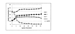
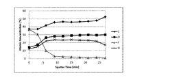
- the concentration distribution of fluorine atoms in the thickness direction in the release layer was measured, and the obtained fluorine atom concentration distribution (vertical axis: fluorine atom concentration (atom%), horizontal axis: sputtering time (min)) was calculated as total sputtering.
- the fluorine atom concentration (atom%) at the second measurement point to the tenth measurement point is 80.0% or less of the fluorine atom concentration (atom%) at the first measurement point (sputtering time 0), that is, the first measurement point (sputtering).
- a release film characterized in that when the fluorine atom concentration (atom%) at time 0) is 100.0%, it is 80.0% or less.
- the present invention also contains (A) a curable silicone having a fluorine substituent, (B) a curable silicone containing no fluorine substituent, and (D) a curing catalyst on at least one side of the base film.
- a curable silicone having a fluorine substituent (B) a curable silicone containing no fluorine substituent, and (D) a curing catalyst on at least one side of the base film.
- GC-IB gas cluster ion beam
- XPS X-ray photoelectron spectroscopy
- the concentration distribution of fluorine atoms in the thickness direction in the release layer was measured, and the obtained fluorine atom concentration distribution (vertical axis: fluorine atom concentration (atom%), horizontal axis: sputtering time (min)) was calculated as total sputtering.
- first measurement point sputtering time 0
- second measurement point sputtering time 0
- tenth measurement point sputtering time 0
- the average fluorine atom concentration (atom%) at the 6th to 10th measurement points is higher than 2.2% of the fluorine atom concentration (atom%) at the 1st measurement point (sputtering time 0), that is, the 1st measurement point.
- the present invention also mixes (A) a curable silicone having a fluorine substituent, (C) a silicone cross-linking agent, and (D) a curing catalyst, and then stirs and / or stands (in the present invention, this treatment). (Also referred to as "pretreatment"), then (B) a release layer composition is prepared by mixing with a curable silicone having no fluorine substituent, and this release layer composition is used on at least one side of the base film.
- pretreatment a method for producing a release film, which is characterized by being applied to the side.
- the first and second release films proposed by the present invention relate to a release layer formed by using fluorinated silicone, and have a concentration distribution of fluorine atoms in the release layer in the thickness direction on the surface of the release layer. By making the fluorine unevenly distributed, it has a light release property with respect to the silicone pressure-sensitive adhesive layer, and yet the amount of the fluorinated silicone used can be reduced. Further, in the third release film proposed by the present invention, regarding the release layer formed by using fluorinated silicone, the durability of the release layer is increased by allowing fluorine to be present inside the release layer. The sex can be improved. Further, according to the method for producing a release film proposed by the present invention, such a release film can be preferably produced.
- each atomic concentration distribution of carbon (C), oxygen (O), silicon (Si) and fluorine (F) (vertical axis: each atom). It is a graph which showed the concentration (atom%), the horizontal axis: sputter time (min).
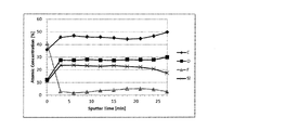
- each atomic concentration distribution of carbon (C), oxygen (O), silicon (Si) and fluorine (F) (vertical axis: each atom). It is a graph which showed the concentration (atom%), the horizontal axis: sputter time (min).
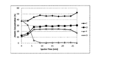
- each atomic concentration distribution of carbon (C), oxygen (O), silicon (Si) and fluorine (F) (vertical axis: each atom). It is a graph which showed the concentration (atom%), the horizontal axis: sputter time (min).
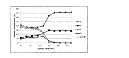
- each atomic concentration distribution of carbon (C), oxygen (O), silicon (Si) and fluorine (F) (vertical axis: each atom). It is a graph which showed the concentration (atom%), the horizontal axis: sputter time (min).
- the release film (referred to as “the present release film”) according to an example of the embodiment of the present invention has (A) fluorine substitution on one side or both sides of the base film (referred to as the "main base film”).
- Curable silicone having a group also referred to as “fluorinated curable silicone”
- B curable silicone containing no fluorine substituent
- non-fluorinated curable silicone also referred to as “non-fluorinated curable silicone
- a release layer (referred to as “main release layer”) obtained by curing a release layer composition (referred to as “main release layer composition") containing (C) a silicone cross-linking agent. ) Is provided.
- the release layer is a layer obtained by curing the release layer composition, and in the concentration distribution of fluorine atoms in the thickness direction in the release layer, fluorine is unevenly distributed on the surface of the release layer. preferable. By unevenly distributing fluorine on the surface of the release layer in this way, it is possible to realize excellent light peelability that is easy to peel off from the silicone pressure-sensitive adhesive layer, and it is possible to reduce the amount of fluorinated silicone used. ..
- This release layer uses GC-IB (gas cluster ion beam) for XPS (X-ray photoelectron spectroscopy) and targets fluorine (F) atoms in the thickness direction in the release layer at a constant sputtering rate.
- concentration distribution ratio
- the concentration distribution (ratio) was measured, and the obtained fluorine atom concentration distribution (vertical axis: fluorine atom concentration (atom%), horizontal axis: sputtering time (min)) was evenly divided into 9 by the total sputtering time. , 1st measurement point (sputtering time 0), 2nd measurement point, ...
- the 1st measurement point (sputtering time 0), that is, the fluorine atom concentration (atom%) on the surface of the release layer.
- the fluorine atom concentration (atom%) on the surface of the release layer is 39.0% or more, particularly preferably 39.5% or more, and more preferably 40.0% or more.
- the upper limit is not limited, but is generally 60.0% or less, especially 50.0% or less.
- the fluorine atom concentration (atom%) at the second measurement point to the tenth measurement point was set to 100.0%
- the fluorine atom concentration (atom%) at the first measurement point (sputtering time 0) was set to 100.0%.
- it is preferably 80.0% or less, particularly preferably 70.0% or less, particularly preferably 60.0% or less, and further preferably 40.0% or less, and among them, 30% or less. It is particularly preferable to have.
- the lower limit is not specified. However, it is generally higher than 2.2%, and more preferably 3.0% or more, particularly 4.0% or more, and particularly 5.0% or more.
- the sputtering time correlates with the depth from the surface of the main release layer, the sputtering time can be read as an index of the depth from the surface of the main release layer.
- the method is not limited to this method.
- the average fluorine atom concentration (atom%) at the 6th measurement point to the 10th measurement point is 100.0% when the fluorine atom concentration (atom%) at the 1st measurement point (sputtering time 0) is 100.0%. It is preferably higher than 2.2%, more preferably 3.0% or more, more preferably 4.0% or more, and even more preferably 5.0% or more. However, from the viewpoint of unevenly distributing fluorine on the surface of the release layer, it is preferably 30.0% or less, more preferably 20.0% or less, and more preferably 10.0% or less. .. By performing the "pretreatment" described later, more fluorine is distributed inside the release layer (closer to the base material) than in the case where the prereaction is not performed.
- the intermediate (one or more cross-linking agents are bonded to the fluorinated silicone resin, but the cross-linking reaction between the fluorinated silicone resins is up to the reaction product of the reaction product by "pretreatment". It is presumed that fluorine derived from (not yet reached) and by-products is distributed. In order to make the fluorine unevenly distributed on the surface of the release layer and to contain a certain amount of fluorine inside the release layer as described above, it is preferable to perform the "pretreatment" described later more sufficiently. .. However, the method is not limited to this method.
- each of the above ratios may be obtained by using the depth from the surface of the release layer instead of the sputtering time. ..
- the fluorine atom concentration (atom%) if the distance between the release layer surface and the base layer, that is, the base film is not exactly 9 sections due to the film thickness fluctuation at the time of preparing the measurement sample, another parameter is used.
- the concentration of fluorine atoms (atom%) at the 1st to 10th measurement points may be calculated by performing conversion using the above and redividing into 9 sections.
- the fluorine atom content in the release layer is preferably 500 mass ppm or more, particularly 1000 mass ppm or more, and among them, from the viewpoint of being able to stably obtain preferable light peelability with respect to the silicone pressure-sensitive adhesive. It is more preferably 3000 mass ppm or more. On the other hand, from the viewpoint of reducing the amount of fluorinated silicone used to reduce the fluorine atom content, it is preferably 800,000 mass ppm or less, particularly 700,000 mass ppm or less, among which 500,000 mass ppm or less, and among them 300,000 mass ppm. The following is more preferable.
- the release layer composition contains (A) a curable silicone having a fluorine substituent, (B) a curable silicone containing no fluorine substituent, and (D) a curing catalyst, and further (C) if necessary. ) A composition containing a silicone cross-linking agent.
- (A) Curable silicone having a fluorine substituent The curable silicone having a fluorine substituent can impart stable light peelability to the silicone pressure-sensitive adhesive.
- silicone (Silicone) has a siloxane bond ( ⁇ Si-O-Si ⁇ ) composed of silicon and oxygen as a skeleton, and an organic group mainly composed of methyl (-CH 3 ) is bonded to the silicon (Si). It is a polymer.
- “Curing silicone” is a silicone that can be cured by cross-linking reaction by heating or light irradiation (ultraviolet rays).
- fluorine substituent refers to a substituent containing a fluorine atom.
- the substituent containing a fluorine atom is not particularly limited as long as the substituent contains a fluorine atom.
- a fluorine group a trifluoromethyl group, a pentafluoroethyl group, a 2,2-trifluoroethyl group, a 1H, 1H-heptafluorobutyl group, a 2H-hexafluoroisopropyl group, and a perfluoro-t-butyl group.
- Perfluorohexyl group and the like. However, it is not limited to these.
- a resin containing a fluorine substituent in the side chain portion of the resin skeleton can be mentioned.
- curable silicone having a fluorine substituent examples include KP-911, X-70-201S, and X-41-3035 manufactured by Shin-Etsu Chemical Co., Ltd .; FS1265-300CS manufactured by Toray Dow Corning Co., Ltd. , FS1265-1000CS, FS1265-10000CS, BY24-900, BY24-903, 3062, Q2-7785, SYL-OFF 7792, SYL-OFF 7795 and the like. However, it is not limited to these.
- the curable silicone having a fluorine substituent may be a solvent type, a solvent-free type, or a mixture thereof.
- the curable silicone having a fluorine substituent may be used alone or in combination of two or more.
- the "solvent-free curable silicone” is a silicone having a viscosity that can be applied without being diluted with a solvent, and is a silicone having a short polysiloxane chain and a relatively low molecular weight.
- the viscosity of the solvent-free curable silicone is preferably 1000 mPa ⁇ s or less by itself, more preferably 50 mPa ⁇ s or more or 900 mPa ⁇ s or less, and more preferably 80 mPa ⁇ s or more or 800 mPa ⁇ s or less. .. This point also applies to (B) a curable silicone that does not contain a fluorine substituent.
- the "solvent-type curable silicone” is a silicone having a viscosity so high that it cannot be coated unless it is diluted with a solvent, and is a silicone having a relatively high molecular weight.
- the viscosity of the solvent-type curable silicone is preferably 1000 mPa ⁇ s or more when made into a 30% toluene solution, among which 2000 mPa ⁇ s or more or 20000 mPa ⁇ s or less, among which 3000 mPa ⁇ s or more or 18000 mPa ⁇ s. The following is more preferable. Since the solvent-type curable silicone has a high viscosity, the adhesion to the base film tends to be improved. This point also applies to (B) a curable silicone that does not contain a fluorine substituent.
- the fluorine atom content (atomic number fraction) of a curable silicone having a fluorine substituent is generally several thousand ppm (less than 1% of the total number of atoms in the "curable silicone having a fluorine substituent") to several. It is about 100,000 ppm (several tens of percent of the total number of atoms in "curable silicone having a fluorine substituent").
- the curable silicone containing no fluorine substituent may be a solvent type, a solvent-free type, or a mixture thereof. Above all, from the viewpoint of stably obtaining light peelability to the silicone pressure-sensitive adhesive, (B) the curable silicone containing no fluorine substituent is preferably a solvent-based curable silicone.
- curable silicone containing no fluorine substituent examples include KNS-3051, KNS-320A, KNS-316, KNS-3002, KNS-3300, X-62-1387, manufactured by Shin-Etsu Chemical Co., Ltd. KS-837, X-62-2829, KS-3650, KS-847, KS-847T, KS-776L, KS-776A, KS-774, KS-3703T, KS-3601, KS-830E, X-62- 2825, X-62-9201-A, X-62-9201B, KM3951, KM-768, X-52-6015, KF-2005, X-62-7205, X-62-7028-A, X-62- 7028-B, X-62-7052, X-62-7622, X-62-7660, X-62-7655; SP7017, SP7015, SP7025, SP7031, LTC1006L, L
- LTC1056L SRX357, SRX211, SRX345, SRX370, LTC300B, LTC310, LTC355A, LTC759, LTC755, LTC750A, LTC752, LTC761, LTC856, LTC851 and the like.
- LTC1056L SRX357, SRX211, SRX345, SRX370, LTC300B, LTC310, LTC355A, LTC759, LTC755, LTC750A, LTC752, LTC761, LTC856, LTC851 and the like.
- LTC1056L SRX357, SRX211, SRX345, SRX370, LTC300B, LTC310, LTC355A, LTC759, LTC755, LTC750A, LTC752, LTC761, LTC856, LTC851 and the like.
- LTC1056L SRX357, SRX211, SRX345, SR
- a heavy peeling additive may be added to the non-fluorinated curable silicone, and examples thereof include KS-3800 manufactured by Shin-Etsu Chemical Co., Ltd .; SD7292 and BY24-4980 manufactured by Toray Dow Corning Co., Ltd. And so on.
- the non-fluorinated curable silicone may be used alone, or two or more kinds having different reactive functional groups and viscosities may be mixed and used.
- the curing reaction can be adjusted, the viscosity of the coating liquid can be adjusted, and the wettability and reactivity can be enhanced.
- the solvent-free silicones may be mixed, the solvent-based silicones may be mixed, or the solvent-free silicone and the solvent-based silicone may be mixed.
- the solid content concentration of the coating liquid forming the cured layer tends to increase.
- the viscosity of the coating liquid increases, and the appearance of the coat deteriorates and the thickness unevenness increases. Therefore, by mixing the solvent-free silicone and the solvent-based silicone, the viscosity of the coating liquid can be lowered, and a cured layer having a good coat appearance and a small thickness blur can be formed.
- the solvent-based curable silicone and the solvent-free curable silicone are as described above, and the preferable viscosity range of each is the same as the above-mentioned range.
- the mass ratio of (A) the curable silicone having a fluorine substituent and (B) the curable silicone not containing a fluorine substituent is 1: 50 to 10: 1. Of these, 1:20 to 5: 1, among them, 1:10 to 2: 1, and even more preferably 1: 5 to 1: 1.
- a curable silicone that is cured by a hydrosilylation addition reaction is used, especially in "(A) a curable silicone having a fluorine substituent" from the viewpoint of material availability. preferable.
- a feature of the present invention is that "in the concentration distribution of fluorine atoms in the release layer in the thickness direction, the concentration of fluorine atoms on the surface of the release layer is higher than that inside the release layer.
- a curable silicone such as a condensation type or a UV curable type may be used.
- crosslinking agent is a compound that links polymers to each other, for example, a compound that can connect two or more molecules by a chemical covalent bond.
- (C1) a silicone cross-linking agent containing no fluorine substituent (also referred to as “non-fluorinated silicone cross-linking agent") and (C2) a silicone cross-linking agent containing a fluorine substituent (non-fluorinated silicone cross-linking agent). Also referred to as).
- (C1) non-fluorinated silicone crosslinks from the viewpoint of enhancing the effect of the pre-reaction described later and the uneven distribution of fluorine, that is, enhancing the light peelability and increasing the residual adhesion rate. It is preferable to use an agent. Further, when both are mixed and used, it is preferable to increase the amount of (C1).
- ((C1) Silicone cross-linking agent containing no fluorine substituent) is represented by the following general formula (1), and at least two, preferably three or more (usually about 3 to 200) in one molecule. More preferably, it has 3 to 100 silicon atoms, and more preferably 3 to 50 silicon atom-bonded hydrogen atoms (SiH groups).
- R is an unsubstituted or substituted monovalent hydrocarbon group having 1 to 10 carbon atoms.
- b is 0.7 to 2.1, particularly 0.8 to 2.0
- c is 0.001 to 1.0
- b + c is 0.8 to 3.0, particularly 1.0 to 2. It is a positive number that satisfies 5.
- R the same group as R in the alkenyl group-containing organopolysiloxane can be mentioned, but one having no aliphatic unsaturated bond such as an alkenyl group is preferable.
- This silicon atom bond The hydrogen atom is bonded to both of these, whether it is bonded to a silicon atom at the end of the molecular chain or to a silicon atom in the middle of the molecular chain (non-terminal of the molecular chain). It may be a thing.
- the molecular structure of the "(C1) silicone cross-linking agent containing no fluorine substituent” may be any of a linear, cyclic, branched, and three-dimensional network structure. Further, the number of silicon atoms (or degree of polymerization) in one molecule is preferably 2 to 1,000, particularly 3 or more or 500 or less, particularly 3 or more or 300 or less, and particularly 4 or more or 150 or less. It is even more preferable to have it.
- Examples of the "(C1) fluorine substituent-free silicone cross-linking agent” include tris (dimethylhydrogensiloxy) methylsilane, tris (dimethylhydrogensiloxy) phenylsilane, 1,1,3,3-tetramethyldisiloxane, and 1 , 3,5,7-Tetramethylcyclotetrasiloxane, methylhydrogencyclopolysiloxane, methylhydrogensiloxane / dimethylsiloxane cyclic copolymer, both-terminal trimethylsiloxy group blockage methylhydrogenpolysiloxane, both-terminal trimethylsiloxy group blockade Dimethylsiloxane / Methylhydrogensyloxy group-blocked dimethylpolysiloxane, both-terminal dimethylhydrogensiloxy group-blocked methylhydrogenpolysiloxane, both-terminal dimethylhydrogensiloxy group-blocked dimethylsi
- the content of "(C1) silicone cross-linking agent containing no fluorine substituent" (the total amount when a plurality of types are used) is 0 with respect to 100 parts by mass of the curable silicone ((A) + (B)). It is preferably 1 to 50 parts by mass, and more preferably 0.3 parts by mass or more or 30 parts by mass or less, and more preferably 0.5 parts by mass or more or 20 parts by mass or less.
- the molar ratio of silicon atom-bonded hydrogen atoms (SiH groups) in the cross-linking agent is preferably 0.3 to 3.0, particularly 0.5 or more or 2.5 or less, and particularly 0.8 or more or It is more preferably 2.0 or less.
- (C1) silicone cross-linking agent containing no fluorine substituent examples include 3062A, 3062B, 3062D, and SP 7297 manufactured by Toray Dow Corning Co., Ltd.
- examples of the (C2) silicone cross-linking agent containing a fluorine substituent include those in which R has a fluoro group in the above formula (1). Specific examples include 3062C and Q2-7560 manufactured by Toray Dow Corning Co., Ltd.
- the "curing catalyst” is a catalyst for promoting the hydrosilylation addition reaction between the alkenyl group bonded to the silicon atom of the curable silicone and the hydrogensilane (SiH) group of the (C) silicone cross-linking agent.
- the curing catalyst include platinum black, second platinum chloride, platinum chloride acid, a reaction product of platinum chloride acid and a monovalent alcohol, a complex of platinum chloride acid and olefins, and a platinum-based catalyst such as platinum bisacetoacetate.
- platinum group metal catalysts such as palladium catalysts and rhodium catalysts. However, it is not limited to these.
- the content of the curing catalyst in the main release layer composition or the main release layer is 0.5 to 500 mass as a metal equivalent amount with respect to the total amount of the curable silicone ((A) + (B)). It is preferably ppm, and more preferably 5 mass ppm or more or 500 mass ppm or less, and more preferably 10 mass ppm or more or 200 mass ppm or less.
- the release layer composition and the release layer may contain a reaction control agent in addition to the above components, if necessary.
- reaction control agent (E) acetylene alcohol or the like represented by the following general formula (2) can be used.
- R 1 is a linear or branched monovalent hydrocarbon group having 5 to 15 carbon atoms
- R 2 is a linear monovalent hydrocarbon group having 1 to 3 carbon atoms. Is. )
- R 1 is preferably a linear or branched monovalent hydrocarbon group having 5 to 15 carbon atoms, more preferably 6 to 14, and particularly 8 to 12. is there.
- R 1 include alkyl groups such as pentyl group, neopentyl group, hexyl group, heptyl group, octyl group, nonyl group, decyl group, undecyl group and dodecyl group, and alkenyl such as pentanyl group, hexenyl group and heptenyl group.
- the group can be mentioned. However, it is not limited to these.
- R 2 is a linear monovalent hydrocarbon group having 1 to 3 carbon atoms, preferably 1 to 2.
- R 2 include alkyl groups such as methyl group, ethyl group and n-propyl group, alkenyl groups such as vinyl group, allyl group and n-propenyl group. However, it is not limited to these. The smaller the number of carbon atoms in R 2, the easier it is to control the silicone composition, and a methyl group is preferable.
- the reaction control agent may be used alone or in combination of two or more, if necessary.
- the content of the reaction control agent is preferably 0.001 to 5.0 parts by mass, particularly 0.01 parts by mass or more or 1.0 part by mass or less, per 100 parts by mass of the total amount of the release layer composition. Among them, it is more preferably 0.05 parts by mass or more or 0.5 parts by mass or less.
- the release layer composition and the release layer may contain other components, if necessary, in addition to the above components.
- Various particles such as silica particles, alumina particles, silicone rubber particles, silicone resin particles, and silicone rubber / resin composite particles; silane coupling agents and the like can be mentioned. However, it is not limited to these.
- the present release layer composition and the present release layer may contain, for example, a light release agent, a heavy release agent, a cross-linking agent, and an adhesion improver, if necessary.
- a light release agent e.g., KS-3800 and X-92-185 manufactured by Shin-Etsu Chemical Co., Ltd .
- the solid content concentration of the release layer composition is preferably 0.1% by mass to 100% by mass, particularly 0.5% by mass or more or 50% by mass or less, and 1.0% by mass or more or more. It is more preferably 20% by mass or less, and more preferably 1.5% by mass or more or 10% by mass or less.
- the solid content of this release layer composition includes alkyl vinyl polysiloxane and alkyl hydrogen polysiloxane.
- the preferable amount of the alkyl vinyl polyloxane containing a vinyl group (alkenyl group) is 85.0 to 99.9% by mass, particularly 90.0% by mass or more or 99. It is more preferably 5% by mass or less, particularly 92.0% by mass or more or 99.0% by mass or less.
- the film thickness of the release layer is not particularly limited. If the film thickness of the release layer is thick, it is difficult to convey the influence of the base material, for example, the influence of the hardness of the base material to the release surface of the release film, which is preferable. Therefore, the thickness is preferably 0.01 ⁇ m or more. Of these, 0.05 ⁇ m or more, and more preferably 0.10 ⁇ m or more. On the other hand, if the film thickness of the release layer is too thick, blocking may occur and the appearance of the coat may be deteriorated. Therefore, the thickness is preferably 10 ⁇ m or less, particularly 5 ⁇ m or less, and 1 ⁇ m or less among them, 0. It is more preferably 5 ⁇ m or less, and particularly preferably 0.25 ⁇ m or less.
- the material of the base film is not particularly limited as long as it exhibits a film shape.
- it may be made of paper, resin, metal, or the like. Among these, it is preferably made of resin from the viewpoint of mechanical strength and flexibility.
- the resin-made base film examples include a film formed of a polymer such as polyethylene, polypropylene, polyester, polystyrene, polycarbonate, polyether sulfone, polyamide, and polyimide. However, it is not limited to these. Further, as long as it can be formed into a film, it may be a mixture of these materials (polymer blend) or a composite of constituent units (copolymer).
- the polyester film is particularly preferable because it has excellent physical properties such as heat resistance, flatness, optical properties, and strength.
- the polyester film may be a single layer or a multilayer film (laminated film) having two or more layers having different properties.
- the polyester film may be a non-stretched film (sheet) or a stretched film. Of these, a stretched film stretched in the uniaxial direction or the biaxial direction is preferable. Among them, a biaxially stretched film is more preferable from the viewpoint of balance of mechanical properties and flatness.
- the polyester which is the main component resin of the polyester film may be a homopolyester or a copolymerized polyester.
- the main component resin means the resin having the largest mass ratio among the resins constituting the present polyester film, and is 50% by mass or more, 75% by mass or more, or 90% by mass or more of the resin constituting the present polyester film. It is assumed that it occupies 100% by mass or more or 100% by mass.
- the homopolyester is preferably one obtained by polycondensing an aromatic dicarboxylic acid and an aliphatic glycol.
- aromatic dicarboxylic acid include terephthalic acid and 2,6-naphthalenedicarboxylic acid
- examples of the aliphatic glycol include ethylene glycol, diethylene glycol, 1,4-butanediol, 1,4-cyclohexanedimethanol and the like. Can be mentioned. However, it is not limited to these.
- PET polyethylene terephthalate
- PBT polybutylene terephthalate
- the polyester when it is a copolymerized polyester, it is preferably a copolymer containing 30 mol% or less of a third component.
- the dicarboxylic acid component of the copolymerized polyester include one or more of isophthalic acid, phthalic acid, terephthalic acid, 2,6-naphthalenedicarboxylic acid, adipic acid, sebacic acid and the like, and ethylene glycol, as the glycol component.
- diethylene glycol, propylene glycol, 1,4-butanediol, 1,4-cyclohexanedimethanol, neopentyl glycol and the like can be mentioned. However, it is not limited to these.
- polyethylene terephthalate in which 60 mol% or more, preferably 80 mol% or more is an ethylene terephthalate unit is preferable.
- This base film can also contain particles for the main purpose of imparting slipperiness and preventing scratches in each process.
- the type of particles contained is not particularly limited as long as the particles can impart slipperiness, and specific examples thereof include silica, calcium carbonate, magnesium carbonate, barium carbonate, and sulfuric acid.
- examples thereof include inorganic particles such as calcium, calcium phosphate, magnesium phosphate, kaolin, aluminum oxide and titanium oxide, and organic particles such as acrylic resin, styrene resin, urea resin, phenol resin, epoxy resin and benzoguanamine resin. However, it is not limited to these.
- precipitated particles in which a part of a metal compound such as a catalyst is precipitated and finely dispersed can also be used.
- the shape of the particles to be used is not particularly limited, and any of spherical, lumpy, rod-shaped, flat-shaped and the like may be used. Further, the hardness, specific gravity, color and the like are not particularly limited. Two or more kinds of these series of particles may be used in combination, if necessary.
- the average particle size of the particles is preferably in the range of 5 ⁇ m or less, more preferably 0.1 ⁇ m or more or 3 ⁇ m or less. By using the average particle size in the above range, an appropriate surface roughness can be given to the film, and good slipperiness and smoothness can be ensured.
- the average particle size of the particles can be measured as follows.
- the average particle size of the particles as a raw material can be measured as the average particle size (D50) obtained from the volume-based particle size distribution measured by a dynamic light scattering method or the like.
- the average particle size of the particles contained in the base film is determined by observing the surface or cross section of the base film using an optical microscope or a scanning electron microscope (SEM) and measuring 10 or more particles. The diameter can be measured and calculated as the average value. At that time, when the cross-sectional shape is elliptical, the average value of the longest diameter and the shortest diameter can be measured as the diameter of each particle.
- the particle content in the base film is preferably in the range of 5% by mass or less, more preferably 0.0003% by mass or more or 3% by mass or less.
- the transparency of the film becomes high and a good film is obtained, but the slipperiness may be insufficient. Therefore, the slipperiness is improved by putting particles in the coating layer. It may be necessary to devise such as. If the particle content is too high, the transparency of the film may be insufficient.
- the release film may have a configuration in which the release layer is provided on one side or both sides of the base film, as will be described later, the release film is formed on one side or both sides of the release film.
- the material film and the release layer may be directly laminated or may be laminated via another layer.
- the “other layer” examples include an anchor coat layer for enhancing the adhesion between the base film and the release layer, and exudation (bleeding, plate-out) of a compound or oligomer onto the film surface.
- examples thereof include an oligomer-sealing layer for sealing, an antistatic layer having antistatic properties, and the like. However, it is not limited to these.
- main release film examples include the main base film / main release layer, the main base film / anchor coat layer / main release layer, the main base film / antistatic layer / main release layer, and the like.
- Anchor coat layer examples include those containing a polymer material such as polyethylene, polypropylene, a styrene-based copolymer, polyester, polyurethane, polyvinyl alcohol, polyethyleneimine, polyacrylate, polymethacrylate, and modified products thereof. Can be done. However, it is not limited to these.
- the oligomer-sealing layer may contain a hydrolyzable alkoxysilicate and / or a polycondensate thereof.
- hydrolyzable alkoxysilicate include a structure represented by the following general formula (3) (R 1 represents a hydrocarbon group having 1 to 10 carbon atoms).
- R 1 represents a hydrocarbon group having 1 to 10 carbon atoms.
- the oligomer-sealing layer may further contain inorganic particles, and specific examples of the inorganic particles include silica, alumina, kaolin, calcium carbonate, titanium oxide, and barium salt. However, it is not limited to these. Further, even if the oligomer encapsulating layer contains an antifoaming agent, a coatability improving agent, a thickener, an organic lubricant, organic polymer particles, an antioxidant, an ultraviolet absorber foaming agent, a dye, or the like. Good. However, it is not limited to these.
- the antistatic layer preferably contains a conductive polymer and a binder polymer from the viewpoint of imparting antistatic properties.
- other components may be contained in the coating liquid as long as the gist of the present invention is not impaired.
- the conductive polymer preferably contains polythiophene represented by the following formula (4) and its derivative (I).
- R1 and R2 independently represent a hydrogen element, an aliphatic hydrocarbon group having 1 to 12 carbon atoms, an alicyclic hydrocarbon group, or an aromatic hydrocarbon group, for example, a methyl group. , Ethyl group, propyl group, isopropyl group, butyl group, cyclohexylene group, benzene group and the like. However, it is not limited to these.
- the layers such as the anchor coat layer, the antistatic layer, and the oligomer encapsulation layer are formed by an in-line coating method in which a film-like base material is formed at the same time as the film is formed, or by a separate process on the film-formed base material film. It can be formed by adopting either of the offline coating methods.
- a specific example of the in-line coating method is, for example, a method of coating at an arbitrary stage from melt extrusion of polyester to biaxial stretching, heat fixing, and winding. Usually, it is coated on any of a substantially amorphous unstretched sheet obtained by melting and quenching, a uniaxially stretched film stretched in the longitudinal direction (longitudinal direction), and a biaxially stretched film before heat fixing. How to do it.
- the content ratio of fluorinated silicone in the release layer may be reduced, or the release layer may be reduced. Measures such as reducing the film thickness can be considered.
- the former method impairs the light peelability, which is the original purpose, and the latter method has problems such as the release layer cannot be formed uniformly and the stability of the peeling force is lowered. is there.
- (A) a curable silicone having a fluorine substituent referred to as "fluorinated curable silicone”
- (B) a curable silicone containing no fluorine substituent also referred to as “non-fluorinated curable silicone”
- fluorinated curable silicone a curable silicone having a fluorine substituent
- non-fluorinated curable silicone also referred to as “non-fluorinated curable silicone”
- the silicone cross-linking agent and catalyst used in combination do not have the same high hydrophobicity as (A) fluorinated-curable silicone due to their molecular structure, so they do not disperse uniformly in the film and are good. Problems such as not being able to obtain a release layer having a good cured state and (B) being unable to mix a large amount of non-fluorinated curable silicone have been confirmed. Therefore, in the present invention, in forming the release layer, first, (A) a curable silicone having a fluorine substituent, (C) a silicone cross-linking agent and (D) a curing catalyst are mixed, and stirred and / or allowed to stand.
- the above-mentioned (C) silicone cross-linking agent is prepared by preparing a release layer composition by mixing (B) a curable silicone having no fluorine substituent and then performing a treatment of reacting with the silicone, that is, a "pretreatment”. (C1) Even when a silicone cross-linking agent having no fluorine substituent is used, it can be uniformly dispersed and is more easily peeled off from the silicone pressure-sensitive adhesive (light peelability). Film formation can be realized.
- a preferable production method of the release film for example, (A) fluorinated-curable silicone, (C) silicone cross-linking agent and (D) curing catalyst are mixed, and then stirred and / or allowed to stand. "Pretreatment” is carried out, and then the pretreatment composition obtained by the pretreatment and (B) non-fluorinated curable silicone are mixed to prepare a main release layer composition, and this main release type is prepared.
- a method of producing a release film by applying the layer composition to at least one side of the base film can be mentioned. However, it is not limited to this manufacturing method.
- reaction control agent acetylene alcohol derivative or the like
- the reaction control agent may be added to the non-fluorinated curable silicone (or a compounding solution thereof) described later.
- (C) silicone cross-linking agent As the (C) silicone cross-linking agent, as described above, it is preferable to use a silicone cross-linking agent that does not contain a fluorine substituent.
- the solvent for dilution may be a polar solvent or a non-polar solvent. Further, two or more kinds of the above solvents may be mixed and used.
- the polar solvent include ethanol, alcohols such as (iso) propyl alcohol, methyl acetate, ethyl acetate, (iso) propyl acetate, (iso) butyl acetate, (iso) pentyl acetate, ethyl lactate, ethyl benzoate and the like.
- Esters methyl ethyl ketone, methyl isobutyl ketone, cyclopentanone, cyclohexanone, diacetone alcohol, diisobutyl ketone and other ketones, ethylene glycol, ethylene glycol monoethyl ether, ethylene glycol monobutyl ether, propylene glycol monomethyl ether acetate, propylene glycol monomethyl Examples thereof include glycols such as ether, N-methyl-2-pyrrolidone, N, N-dimethylformamide, tetrahydrofuran, acetonitrile and the like. However, it is not limited to these.
- non-polar solvent examples include aromatic hydrocarbons such as benzene, toluene and xylene, aliphatic hydrocarbons such as hexane, heptane and octane, hydrocarbons having a branched structure such as isohexane, isooctane and isononane, and cyclohexane. , Cycloheptane, alicyclic hydrocarbons such as cyclooctane, ethers such as diisopropyl ether, dioxane and the like.
- fluorine solvent examples include hydrofluoroethers, metaxylene hexafluoride, and tridecafluorooctane. However, it is not limited to these.
- a coating technique as shown in "Coating method” (written by Yuji Harasaki, Maki Shoten, published in 1979) can be used.
- a coating head air doctor coater, blade coater, rod coater, knife coater, squeeze coater, impregnation coater, reverse roll coater, transfer coater, gravure coater, kiss roll coater, cast coater, spray coater, curtain coater, calendar coater.
- Extrusion coater and the like are exemplified. However, it is not limited to these.
- the release film is released after forming "other layers” such as an anchor coat layer, an antistatic layer, and an oligomer encapsulation layer on one or both sides of the base film, if necessary.
- the layer composition can be applied and cured to form.
- an anchor coat layer, an antistatic layer, an oligomer encapsulation layer, etc. are formed on at least one side of the base film unwound from the roll state, if necessary.
- the release layer composition is applied and cured to form the release layer.
- This release film can have the following physical characteristics.
- the normal peeling force of the release layer is preferably 75 mN / cm or less, more preferably 60 mN / cm or less, particularly 50 mN / cm or less, and particularly preferably 40 mN / cm or less.
- the lower the normal peeling force the smaller the force required for peeling from the silicone adhesive, and it is possible to suppress defects such as peeling failure and adhesive layer deformation in the production process.
- a release film having excellent light peelability it is possible to prevent a phenomenon in which the release film on the unintended side is peeled off in the double-sided adhesive tape provided with the release films on both sides of the pressure-sensitive adhesive sheet.
- the lower limit is not particularly limited.
- the normal peeling force was obtained by laminating the adhesive tape "Polyimide tape with silicone adhesive No. 5413 (manufactured by 3M)" with a width of 5 cm, and peeling 180 ° by a peeling tester at room temperature, that is, at 23 ° C. It can be measured under the condition of 3 m / min.
- the heat peeling force of the release layer is preferably 100 mN / cm or less, more preferably 80 mN / cm or less, and particularly preferably 60 mN / cm or less. It is considered that the heat peeling force correlates with the reactive groups (hydrogensilane group (Si—H group) and the like) remaining on the surface of the release layer after curing and forming on the film. The closer the value is to the normal peeling force, the smaller the amount of reactive groups remaining on the surface.
- the heat-removing force is determined by attaching the adhesive tape "Polyimide tape with silicone adhesive No.
- the residual adhesion ratio of the release layer is preferably 80% or more, more preferably 90% or more, and further preferably 95% or more. By satisfying the above range, the transfer of the release layer component from the surface to the surface of the mating adherend to be bonded is reduced.
- the residual adhesive rate is an index for confirming the transfer of the release agent, and usually, the adhesive force after peeling by attaching an adhesive tape to the release agent coated surface or the like is measured in an environment of room temperature, that is, 23 ° C. Is the value displayed by the ratio divided by the initial adhesive strength (JIS Z 0109: 2015).
- the film laminate As a film laminate (referred to as "the film laminate") according to an example of the embodiment of the present invention, the above-mentioned release film is attached to "a laminated film having a functional layer" via a silicone adhesive layer. Examples thereof include those having a combined configuration.
- laminated film having a functional layer includes, for example, a laminated film having a crosslinked resin layer, that is, a layer having a structure in which a resin is crosslinked, on at least one side of a base film (“laminated film (1)). ”).
- the crosslinked resin layer may be exemplified from, for example, a crosslinked resin layer composition containing a conductive polymer and a binder polymer, a crosslinking agent if necessary, and particles.
- Conductive polymer As the conductive polymer, it is preferable to contain a composition composed of polythiophene and polyanions, or a composition composed of the polythiophene derivative and polyanions.
- the polyanion refers to an "acidic polymer in a free acid state", and a high molecular carboxylic acid, a high molecular sulfonic acid, a polyvinyl sulfonic acid, or the like is preferable.
- Specific examples of the high molecular weight carboxylic acid include polyacrylic acid, polymethacrylic acid, and polymaleic acid.
- Polystyrene sulfonic acid is exemplified as a specific example of the high molecular weight sulfonic acid. Of these, polystyrene sulfonic acid is most preferable in terms of conductivity. In addition, it may take the form of a salt in which a part of the free acid is neutralized.
- the polythiophene-based compound which is originally insoluble in water can be easily dispersed or made water-based, and the function as an acid also functions as a doping agent for the polythiophene-based compound. ..
- the polymer carboxylic acid and the polymer sulfonic acid can also be used in the form of being copolymerized with other copolymerizable monomers such as acrylic acid ester, methacrylic acid ester and styrene.
- the molecular weight of the polymer carboxylic acid or polymer sulfonic acid used as the polyanion is not particularly limited, but the mass average molecular weight thereof is preferably 1000 to 1000000, more preferably 5000, in terms of stability and conductivity of the coating material. ⁇ 150,000.
- Alkaline salts such as lithium salt and sodium salt, ammonium salt and the like may be partially contained as long as the characteristics of the present invention are not impaired.
- the poly-anion is present in excess of the polythiophene or the polythiophene derivative in terms of solid content mass ratio in terms of conductivity.
- the polythiophene or the polythiophene derivative is 1 part by mass and the poly-anion is 1 mass by mass. Parts to 5 parts by mass are preferable, and 1 part to 3 parts by mass is more preferable.
- the composition consisting of the above polythiophene or polythiophene derivative and polyanion for example, JP-A-6-295016, JP-A-7-292801, JP-A 1-313521, JP-A-2000-6324, Europe. Although there are examples described in Japanese Patent EP602731, US Pat. No.
- 3,4-ethylenedioxythiophene is obtained by using an alkali metal salt of 3,4-dihydroxythiophene-2,5-dicarboxyester as a starting material, and then potassium peroxodisulfate is added to an aqueous polystyrene sulfonate solution. And iron sulfate and the previously obtained 3,4-ethylenedioxythiophene are introduced and reacted, and polythiophene such as poly (3,4-ethylenedioxythiophene) is compounded with polyanions such as polystyrene sulfonic acid. Obtain an embodied composition.
- the binder polymer constituting the crosslinked resin layer composition is a number average measured by gel permeation chromatography (GPC) according to the polymer compound safety evaluation flow scheme (sponsored by the Chemical Substances Council in November 1985). It is defined as a polymer compound having a molecular weight (Mn) of 1000 or more and having a film-forming property.
- the binder polymer constituting the crosslinked resin layer composition may be a thermosetting resin or a thermoplastic resin as long as it can be compatible with or mixed and dispersed with the ionic polymer.
- polyesters such as polyethylene terephthalate, polybutylene terephthalate, and polyethylene naphthalate; polyimides such as polyimide and polyamideimide; polyamides such as polyamide 6, polyamide 6, 6, polyamide 12, and polyamide 11; polyvinylidene fluoride, polyvinyl fluoride, and poly.
- Fluorine resins such as tetrafluoroethylene, ethylene tetrafluoroethylene copolymer, and polychlorotrifluoroethylene; vinyl resins such as polyvinyl alcohol, polyvinyl ether, polyvinyl butyral, polyvinyl acetate, and polyvinyl chloride; epoxy resins; oxetane resins; xylene resins; Examples thereof include aramid resin; polyimide silicone; polyurethane; polyurea; melamine resin; phenol resin; polyether; acrylic resin and copolymers thereof. These may be used alone or in combination of two or more. However, it is not limited to these.
- the binder polymer may be dissolved in an organic solvent as a raw material, or may be water-dispersed by adding a functional group such as a hydroxyl group, a sulfo group or a carboxy group to an aqueous solution or using a surfactant in combination. You may. Further, the binder polymer may be used in combination with a curing agent such as a cross-linking agent and a polymerization initiator, a polymerization accelerator, a solvent, a viscosity modifier and the like, if necessary.
- a curing agent such as a cross-linking agent and a polymerization initiator, a polymerization accelerator, a solvent, a viscosity modifier and the like, if necessary.
- binder polymers it is preferable to use any one or more selected from polyester resin, acrylic resin, urethane resin, and vinyl resin from the viewpoint of adhesion to the release layer.
- the content of the binder polymer in the crosslinked resin layer composition is preferably 5 to 90% by mass, more preferably 10 to 70% by mass, and further preferably 10 to 60% by mass in terms of solid content mass ratio. is there.
- the content of the binder polymer is within the above range, the strength of the obtained crosslinked resin layer and the adhesion to the release layer can be sufficiently obtained.
- the crosslinked resin layer composition may contain a crosslinking agent, if necessary.
- the cross-linking agent mainly improves the cohesiveness, surface hardness, scratch resistance, solvent resistance, water resistance, etc. of the cross-linked resin layer by a cross-linking reaction with a functional group contained in another resin or compound and self-cross-linking. be able to.
- the cross-linking agent can be any kind of cross-linking agent.
- cross-linking agent for example, melamine compounds, guanamine-based, alkylamide-based, and polyamide-based compounds, glyoxal-based, carbodiimide compounds, epoxy compounds, oxazoline compounds, aziridine compounds, isocyanate compounds, silane coupling agents, dialcohol aluminate-based coupling agents, di Aldehyde compounds, zircoaluminate-based coupling agents, peroxides, heat- or photoreactive vinyl compounds, photosensitive resins and the like are preferably used.
- cross-linking agent for a melamine compound or an epoxy compound or a silane coupling agent.
- these cross-linking agents also include polymer-type cross-linking reactive compounds having a reactive group in another polymer skeleton, and in the present invention, one or more of these cross-linking agents are used in combination. You may.
- the content of the cross-linking agent in the cross-linked resin layer composition is preferably 1 to 90% by mass, more preferably 3 to 50% by mass, and further preferably 5% by mass to 40% by mass in terms of solid content mass ratio. %.
- the ratio of the cross-linking agent is within the above range, sufficient adhesion to the release layer due to synergistic action with the binder polymer can be obtained.
- the crosslinked resin layer may contain particles for the purpose of improving the adhesiveness and slipperiness of the crosslinked resin layer.
- the average particle size of the particles is not particularly limited. For example, when used for optical applications, it is preferably 1.0 ⁇ m or less, more preferably 0.5 ⁇ m or less, and further preferably 0.2 ⁇ m or less from the viewpoint of film transparency. Further, it is preferably 0.01 ⁇ m or more from the viewpoint of improving the adhesiveness and slipperiness of the crosslinked resin layer.
- the particles include inert inorganic particles such as silica, alumina, calcium carbonate, and titanium dioxide, polystyrene-based resin, polyacrylic resin, fine particles obtained from polyvinyl-based resin, and organic particles represented by crosslinked particles thereof. Can be mentioned.
- the average particle size of the particles can be measured as follows.
- the average particle size of the particles as a raw material can be measured as the average particle size (D50) obtained from the volume-based particle size distribution measured by a dynamic light scattering method or the like.
- D50 average particle size obtained from the volume-based particle size distribution measured by a dynamic light scattering method or the like.
- For the average particle size of the particles contained in the crosslinked resin layer observe the surface or cross section of the crosslinked resin layer using an optical microscope or a scanning electron microscope (SEM), and determine the diameter of 10 or more particles. It can be measured and calculated as the average value.
- the cross-sectional shape is elliptical
- the average value of the longest diameter and the shortest diameter can be measured as the diameter of each particle.
- the crosslinked resin layer can be used as a surfactant, a defoaming agent, a coating improver, a mold release agent, a thickener, an organic lubricant, an antistatic agent, a conductive agent, a light absorber such as ultraviolet rays, and an antioxidant, if necessary. Agents, foaming agents, dyes, pigments and the like may be contained.
- the components in the crosslinked resin layer can be analyzed by, for example, analysis of TOF-SIMS, ESCA, fluorescent X-rays, and the like.
- the film surface may be treated during the stretching step of the polyester film, which may be provided by in-line coating, or the film may be applied outside the system once manufactured, or an offline coating may be adopted. Good. In-line coating is preferably used because it can be applied at the same time as film formation, can be manufactured at low cost, and the thickness of the crosslinked resin layer can be changed depending on the draw ratio.
- the in-line coating is not limited to the following, but for example, in the sequential biaxial stretching, the coating treatment can be applied especially before the transverse stretching after the longitudinal stretching is completed.
- the crosslinked resin layer is provided on the polyester film by in-line coating, it can be applied at the same time as the film formation, and the crosslinked resin layer can be treated at a high temperature, so that a film suitable as a polyester film can be produced.
- the coating liquid on the polyester film is an aqueous solution or an aqueous dispersion of the crosslinked resin layer composition containing the above-mentioned series of compounds.
- a small amount of an organic solvent may be contained in the coating liquid for the purpose of improving dispersibility in water, improving film-forming property, etc., as long as the gist of the present invention is not impaired.
- One kind or two or more kinds of organic solvents can be used in combination.
- the content of the organic solvent in the coating liquid is preferably 10% by mass or less, more preferably 5% by mass or less.
- organic solvents include aliphatic or alicyclic alcohols such as n-butyl alcohol, n-propyl alcohol, isopropyl alcohol, ethyl alcohol and methyl alcohol, and glycols such as propylene glycol, ethylene glycol and diethylene glycol.
- N-butyl cellosolve N-butyl cellosolve, ethyl cellosolve, methyl cellosolve
- glycol derivatives such as propylene glycol monomethyl ether
- ethers such as dioxane and tetrahydrofuran
- esters such as ethyl acetate and amyl acetate
- ketones such as methyl ethyl ketone and acetone
- N-methylpyrrolidone N-methylpyrrolidone.
- heat treatment and active energy ray irradiation such as ultraviolet irradiation may be used in combination as necessary.
- Examples of the method for forming the crosslinked resin layer include gravure coat, reverse roll coat, die coat, air doctor coat, blade coat, rod coat, bar coat, curtain coat, knife coat, transfer roll coat, squeeze coat, curtain coat, etc.
- Conventionally known coating methods such as impregnation coating, kiss coating, spray coating, calendar coating, and extrusion coating can be used.
- the thickness of the crosslinked resin layer is preferably 0.01 ⁇ m to 3 ⁇ m, especially 0.02 ⁇ m or more or 1 ⁇ m or less, and among them, 0. It is more preferably 03 ⁇ m or more or 0.3 ⁇ m or less.
- the coating amount of the coating liquid containing the crosslinked resin layer composition is usually 0.01 to 3 g / m 2 , preferably 0.01 to 1 g / m 2 , and more preferably 0.01 to 0.3 g / m 2. Is.
- the coating amount can be calculated from the liquid mass per coating time (before drying), the coating liquid non-volatile content concentration, the coating width, the draw ratio, the line speed, and the like.
- Laminated film (2) examples include a release film (referred to as “laminated film (2)") having a “other release layer” on one side of the base film. Can be done.
- a silicone composition containing a curable silicone containing no fluorine substituent as a main component containing a component having a fluorine substituent.
- examples thereof include those having a configuration in which the second layer is sequentially provided.
- Another example of the "other release layer” is a layer formed from a silicone composition containing (A) a curable silicone containing a fluorine substituent as a main component.
- (B) a layer formed from a silicone composition containing a curable silicone containing no fluorine substituent as a main component can be mentioned.
- main component means the component having the largest mass ratio among the constituent components.
- This film laminate is preferably used for laminating in-vehicle members from the viewpoint that a silicone adhesive having good durability and transparency can be used.
- this release film has excellent mold release property with respect to the silicone pressure-sensitive adhesive, it can be used as a light release film for the silicone pressure-sensitive adhesive as follows. That is, the present release film (referred to as "light release film”) is laminated on one side of the silicone pressure-sensitive adhesive layer made of a silicone pressure-sensitive adhesive, and the other side of the silicone pressure-sensitive adhesive layer is more than the release-type film.
- the exposed surface of the silicone pressure-sensitive adhesive layer is "adhered”. It can be used by attaching it to the "body”, curing the silicone pressure-sensitive adhesive layer, and then peeling off the heavy-release film. However, it is not limited to such usage.
- Examples of the adherend include various process papers, interleaving papers, and optical members.
- Examples of the optical member include a polarizing plate and a touch sensor. Further, by utilizing the heat resistance, cold resistance, weather resistance, and high transparency of the silicone adhesive itself, it can be used for in-vehicle use such as a touch panel mounted on an automobile.
- the silicone pressure-sensitive adhesive may be any pressure-sensitive adhesive containing silicone as a main component resin.
- the "main component resin” means a resin having the largest content ratio (mass) among the resins constituting the pressure-sensitive adhesive.
- the silicone pressure-sensitive adhesive include addition reaction type, peroxide curing type, and condensation reaction type silicone pressure-sensitive adhesives. Above all, an addition reaction type silicone pressure-sensitive adhesive is preferably used from the viewpoint that it can be cured at a low temperature in a short time. It should be noted that these addition reaction type silicone pressure-sensitive adhesives are cured when the pressure-sensitive adhesive layer is formed on the support.
- the silicone pressure-sensitive adhesive may contain a catalyst such as a platinum catalyst.
- a catalyst such as a platinum catalyst.
- the addition reaction type silicone pressure-sensitive adhesive is applied onto a support after a silicone resin solution diluted with a solvent such as toluene is added with a catalyst such as a platinum catalyst and stirred so as to be uniform, if necessary. It can be cured at 100 to 130 ° C./1 to 5 minutes.
- a cross-linking agent and an additive for controlling the adhesive force may be added to the addition reaction type silicone pressure-sensitive adhesive, or the support may be primed before the formation of the pressure-sensitive adhesive layer. May be good.
- silicone resin used for the addition reaction type silicone pressure-sensitive adhesive examples include SD4580PSA, SD4584PSA, SD4585PSA, SD4587LPSA, SD4560PSA, SD4570PSA, SD4600FCPSA, SD4593PSA, DC7651ADHESIVE, DC7652ADHESIVE, LTC-755, and LTC-310.
- KR-3700, KR-3701, X-40-3237-1, X-40-3240, X-40-3291-1, X-40-3229, X-40-3323, X-40 -3306, X-40-3270-1 all manufactured by Shin-Etsu Chemical Co., Ltd.
- AS-PSA001, AS-PSA002, AS-PSA003, AS-PSA004, AS-PSA005, AS-PSA012, AS-PSA014, PSA-7465 All manufactured by Arakawa Chemical Industry Co., Ltd.
- TSR1512, TSR1516, TSR1521 all manufactured by Momentive Performance Materials Co., Ltd.
- the material and composition of the polarizing plate are arbitrary.
- a stretched polyvinyl alcohol film using iodine as an orientation dye and a TAC (triacetyl cellulose) film laminated as a protective film have been widely put into practical use as this type of polarizing plate.
- the polarizing plate may have a layer structure on the surface having functions such as a hard coat having substantially no phase difference, antiglare, low reflection, and antistatic.
- the touch sensor is a member that grasps the touch point in response to the contact when the user touches the image displayed on the screen with a finger or a stylus.
- the sensor technology is used to obtain a capacitance method and a resistance film method.
- a method such as a surface wave method using infrared rays or ultrasonic waves is exemplified.
- the touch sensor is mounted on a display device such as a liquid crystal display panel or an organic EL. Further, in recent years, there has been a tendency to use a base film as an alternative to a glass substrate, paying attention to flexibility.
- the touch sensor film is generally provided with a patterned transparent conductive layer for performing the function of the sensing electrode.
- a "sheet” is a thin product according to JIS definition, and its thickness is small and flat for its length and width.
- a “film” is thicker than its length and width.
- JIS K6900 Japanese Industrial Standards
- the term "film” is used to include the “sheet” and is referred to as the "sheet” in the present invention. Even if it is, it shall include "film”.
- X to Y (X, Y are arbitrary numbers) is described, it means “X or more and Y or less” and “preferably larger than X” or “preferably Y”, unless otherwise specified. It also includes the meaning of “smaller”.
- X or more (X is an arbitrary number) is described, it includes the meaning of "preferably larger than X” and is described as “Y or less” (Y is an arbitrary number) unless otherwise specified. In this case, unless otherwise specified, it also includes the meaning of "preferably smaller than Y”.
- the XPS setting conditions are as follows.
- the obtained fluorine atom concentration distribution (vertical axis: fluorine atom concentration (atom%), horizontal axis: sputtering time (min)) is evenly divided into 9 by the total sputtering time, and the first measurement point (sputtering time 0 seconds).
- the surface of the release layer) to the 10th measurement point (base, reaching the base material PET film) were determined, and the fluorine atom concentration (atom%) at each measurement point was determined.
- the ratio (%) of the average fluorine atom concentration (atom%) at the 6th to 10th measurement points was calculated and shown in Table 1.
- a solution a1 was prepared by mixing the following (A) curable silicone having a fluorine substituent, the following (C1) silicone cross-linking agent, and the following (D1) curing catalyst 1. After stirring for 1 minute, the following solution b1 ((B) curable silicone + (D2) curing catalyst 2 containing no fluorine substituent) is mixed so that the mass ratio (solution a1: solution b1) is 1: 2. , A coating solution A1 having a solid content concentration of 3.6% by mass was prepared. Then, on one side of the base film (PET film manufactured by Mitsubishi Chemical Corporation (“T100-38”, thickness 38 ⁇ m)), the coating liquid A1 was applied to No. The film was applied using 4 bars and heat-treated at 150 ° C. for 15 seconds to cure to obtain a release film (sample film) provided with a release layer.
- Solution b1 (B) Curable silicone containing no fluorine substituent ("KS-847H” manufactured by Shin-Etsu Chemical Co., Ltd., solvent type, 30% by mass, containing cross-linking agent / reaction control agent, viscosity 11000 mPa ⁇ s (25 ° C)) 67 Parts by mass (D2) Platinum catalyst 2 (“CAT-PL-50T” manufactured by Shinetsu Chemical Co., Ltd.) 0.67 parts by mass Diisopropyl ether / ethyl acetate (3: 7)
- Example 2> to ⁇ Example 5> a release film (sample film) was obtained in the same manner as in Example 1 except that the solution a1 was stirred for 1 minute and the standing time was added as shown in the table. ..
- Example 6> In Example 1, except that the solution a1 was prepared at a solid content concentration of 10% by mass, stirred for 1 minute, allowed to stand for another 15 minutes, and then diluted with a solvent to obtain a solid content concentration of 3.6% by mass. A release film (sample film) was obtained by manufacturing in the same manner as in 1.
- Example film A release film (sample film) was obtained in the same manner as in Example 1 except that stirring was not performed at all in Example 1.
- “no stirring was performed” means that "(C1) silicone cross-linking agent and (D1) curing catalyst 1 were mixed to prepare solution a1, and then solution b2 was immediately mixed without stirring.
- the coating solution A1 was prepared.
- Example film A release film (sample film) was produced in the same manner as in Example 1 except that (B) a curable silicone containing no fluorine substituent and (D2) a curable catalyst 2 were not mixed in Example 1. Obtained.
- Example 2 instead of (C1) a silicone cross-linking agent containing no fluorine substituent, (C2) a cross-linking agent having a fluorine substituent (Toray Dow Corning Co., Ltd. "3062C") 0.5 parts by mass) was used.
- a release film (sample film) was obtained by producing in the same manner as in Example 2 except that it was blended.
- TPR6600 100 parts by mass as a curable silicone containing no fluorine substituent (including a cross-linking agent not containing a fluorine substituent), LC600 (manufactured by Momentive): 3 parts by mass as a curing catalyst The mixture was mixed and mixed to prepare a solution b2.
- BY24-900 manufactured by Toray Dow Corning Co., Ltd.
- a curable silicone including a cross-linking agent having a fluorine substituent having a fluorine substituent: NC-25 (Toray) as a curing catalyst for 100 parts by mass.
- a solution a2 100 parts by mass containing the curable silicone having a fluorine substituent is mixed with the solution b2: 100 parts by mass containing the curable silicone not containing the fluorine substituent, and mixed with n-heptane.
- a solvent in which methyl isobutyl ketone was mixed at a weight ratio of 1: 1 was added to dissolve the polymer component to prepare a coating solution A2 having a solid content concentration of 3.0% by mass. No stirring was performed before mixing the solution a2 and the solution b2.
- “no stirring was performed” means "after the solution a2 was prepared, the solution b2 was immediately mixed without stirring to prepare the coating liquid A2". Then, the coating liquid A2 was applied to one side of the base film (PET film manufactured by Mitsubishi Chemical Corporation (“T100-38”, thickness 38 ⁇ m)). The film was applied using 10 bars and heat-treated at 120 ° C. for 120 seconds to cure to obtain a release film (sample film) provided with a release layer.
- the base film PET film manufactured by Mitsubishi Chemical Corporation (“T100-38”, thickness 38 ⁇ m
- the coating liquid A3 was applied to No.
- the film was applied using 4 bars and heat-treated at 120 ° C. for 120 seconds to cure to obtain a release film (sample film) provided with a release layer.
- the release layer formed on at least one side of the base film is (A) a curable silicone having a fluorine substituent, and (B) a fluorine substituent.
- Curable silicones that do not contain the above-mentioned silicone and those obtained by curing the release layer composition containing (D) the curing catalyst are easily peeled off from the silicone pressure-sensitive adhesive layer even if the amount of fluorinated silicone used is reduced. It was found to have excellent light release properties.
- the fluorine atom concentration (atom%) at one measurement point (sputtering time 0) was 80.0% or less. Further, if the average fluorine atom concentration (atom%) at the 6th to 10th measurement points is higher than 2.2% of the fluorine atom concentration (atom%) at the 1st measurement point (spatter time 0), it is further excellent. It was found that even if the amount of fluorinated silicone used was reduced, it was possible to obtain an excellent light peelability that was easy to peel off from the silicone pressure-sensitive adhesive layer.
- the release layer was not uniformly dispersed in the film, and a release layer having a good cured state could not be obtained, or (B) a large amount of cured silicone containing no fluorine substituent could not be mixed. Therefore, in the present invention, first, (A) a curable silicone having a fluorine substituent, (C) a silicone cross-linking agent and (D) a curing catalyst are mixed, and the mixture is stirred and / or allowed to stand for reaction. To prepare a release layer composition by mixing (B) a curable silicone having no fluorine substituent with the pretreatment composition obtained by the pretreatment, (C1) a fluorine substituent was obtained.
Landscapes
- Chemical & Material Sciences (AREA)
- Organic Chemistry (AREA)
- Chemical Kinetics & Catalysis (AREA)
- Health & Medical Sciences (AREA)
- Medicinal Chemistry (AREA)
- Polymers & Plastics (AREA)
- Engineering & Computer Science (AREA)
- Materials Engineering (AREA)
- Life Sciences & Earth Sciences (AREA)
- Wood Science & Technology (AREA)
- Manufacturing & Machinery (AREA)
- Laminated Bodies (AREA)
Abstract
Description
シリコーン粘着剤は、これを粘着層としてテープ(フィルム)状にしたものが用いられており、通常、使用する前は、片面又は両面を離型フィルムで被覆した状態で保管され、使用時に当該離型フィルムを剥がして用いることが一般的である。
しかしながら、このようなシリコーン離型フィルムは、シリコーン粘着剤を被覆する場合、剥離剤と粘着剤の化学構造が類似しているため、粘着剤と離型フィルムとの間で強く粘着して剥離し難くなる傾向があった。そのため、シリコーン粘着剤に対する剥離力値を低くすること(軽剥離性化)を目的として、シリコーン剥離剤にフッ素を導入することなどが行われている。例えば、特許文献1には、シリコーン粘着剤に対して剥離性を発現するために、フッ素置換基を有するフッ素化シリコーン材料が提案されている。
第2計測点~第10計測点におけるフッ素原子濃度(atom%)が、第1計測点(スパッタ時間0)におけるフッ素原子濃度(atom%)の80.0%以下、すなわち第1計測点(スパッタ時間0)におけるフッ素原子濃度(atom%)を100.0%とした際にそれの80.0%以下であることを特徴とする離型フィルムを提案する。
第6計測点~第10計測点における平均フッ素原子濃度(atom%)が、第1計測点(スパッタ時間0)におけるフッ素原子濃度(atom%)の2.2%より高い、すなわち第1計測点(スパッタ時間0)におけるフッ素原子濃度(atom%)を100.0%とした際にそれの2.2%より高いことを特徴とする離型フィルムを提案する。
また、本発明が提案する第3の離型フィルムは、フッ素化シリコーンを用いて形成する離型層に関し、当該離型層の内部にフッ素が存在するようにしたことにより、離型層の耐久性を向上させることができる。
また、本発明が提案する離型フィルムの製造方法によれば、そのような離型フィルムを好適に製造することができる。
本発明の実施形態の一例に係る離型フィルム(「本離型フィルム」と称する)は、基材フィルム(「本基材フィルム」と称する)の片面側又は両面側に、(A)フッ素置換基を有する硬化型シリコーン(「フッ素化硬化型シリコーン」とも称する)、(B)フッ素置換基を含まない硬化型シリコーン(「非フッ素化硬化型シリコーン」とも称する)、及び、(D)硬化触媒を含み、必要に応じてさらに(C)シリコーン架橋剤を含む離型層組成物(「本離型層組成物」と称する)が硬化してなる離型層(「本離型層」と称する)を備えたものである。
本離型層は、本離型層組成物が硬化してなる層であり、当該離型層内の厚み方向におけるフッ素原子の濃度分布において、フッ素が離型層表面に偏在しているのが好ましい。
このように離型層表面にフッ素が偏在することにより、シリコーン粘着剤層に対して剥離し易い優れた軽剥離性を実現することができ、しかも、フッ素化シリコーンの使用量を減らすことができる。
ここで、スパッタ時間は、本離型層表面からの深さに相関するから、前記スパッタ時間は本離型層表面からの深さの指標として読み替えることができる。
後述する“事前処理”を行うことで、事前反応を行わなかった場合と比べ、本離型層内部(基材寄り)にもフッ素が多く分布するようになる。その詳細なメカニズムは明らかではないが、“事前処理”による反応生成物である中間体(フッ素化シリコーン樹脂に架橋剤が単独または複数結合しているが、フッ素化シリコーン樹脂同士の架橋反応までは至っていない状態)や副生成物に由来するフッ素が分布するものと推測される。
このようにフッ素を離型層表面に偏在させつつ、且つ、本離型層の内部にもある程度のフッ素を含有させるようにするには、後述する“事前処理”をより十分に行うのが好ましい。但し、かかる方法に限定するものではない。
本離型層組成物は、(A)フッ素置換基を有する硬化型シリコーン、(B)フッ素置換基を含まない硬化型シリコーン、及び、(D)硬化触媒を含み、必要に応じてさらに(C)シリコーン架橋剤を含む組成物である。
フッ素置換基を有する硬化型シリコーンは、シリコーン粘着剤に対する安定した軽剥離性を付与することができる。
なお、「シリコーン(Silicone)」は、ケイ素と酸素からなるシロキサン結合(≡Si-O-Si≡)を骨格とし、そのケイ素(Si)にメチル(-CH3)を主体とする有機基が結合したポリマーである。
「硬化型シリコーン」は、加熱又は光照射(紫外線)によって架橋反応して硬化することができるシリコーンである。
このフッ素原子を含有する置換基(フッ素置換基)は、置換基にフッ素原子が含まれていれば特に限定はされない。具体的には、フッ素基、トリフルオロメチル基、ペンタフルオロエチル基、2,2-トリフルオロエチル基、1H,1H-ヘプタフルオロブチル基、2H-ヘキサフルオロイソプロピル基、パーフルオロ-t-ブチル基、パーフルオロヘキシル基などを挙げることができる。但し、これらに限定するものではない。
また、フッ素置換基を有する成分として、樹脂骨格の側鎖部分にフッ素置換基を含む樹脂を挙げることができる。
フッ素置換基を有する硬化型シリコーンは、単独で用いても、2種類以上を混合して用いてもよい。
無溶剤型硬化型シリコーンの粘度は、単体で1000mPa・s以下であるのが好ましく、中でも50mPa・s以上或いは900mPa・s以下、その中でも80mPa・s以上或いは800mPa・s以下であるのがさらに好ましい。この点は、(B)フッ素置換基を含まない硬化型シリコーンについても同様である。
溶剤型硬化型シリコーンの粘度は、30%トルエン溶液とした時の粘度が1000mPa・s以上であるのが好ましく、中でも2000mPa・s以上或いは20000mPa・s以下、その中でも3000mPa・s以上或いは18000mPa・s以下であるのがさらに好ましい。溶剤型硬化型シリコーンが高い粘度を有することにより、基材フィルムとの密着性が高まる傾向にある。この点は、(B)フッ素置換基を含まない硬化型シリコーンについても同様である。
フッ素置換基を含まない硬化型シリコーンは、溶剤型であっても、無溶剤型であっても、これらを混合したものであってもよい。中でも、安定的にシリコーン粘着剤への軽剥離性を得るための観点から、(B)フッ素置換基を含まない硬化型シリコーンは、溶剤型硬化型シリコーンであるのが好ましい。
2種類以上の非フッ素化硬化型シリコーンを混合することにより、硬化反応を調整したり、塗布液粘度を調整したり、さらには、濡れ性および反応性を高めたりすることができる。その際、無溶剤型シリコーン同士を混合するようにしても、溶剤型シリコーン同士を混合するようにしても、無溶剤型シリコーンと溶剤型シリコーンを混合するようにしてもよい。特に、より軽剥離な離型フィルムを得るため、膜厚を厚くする場合は、硬化層を形成する塗布液の固形分濃度は高くなる傾向にある。そのため、塗布液の粘度が高まり、コート外観の悪化や厚みムラが大きくなるという問題が生じる可能性がある。そこで、無溶剤型シリコーンと溶剤型シリコーンを混合することで、塗布液の粘度を低下させ、良好なコート外観および小さな厚みブレを有する硬化層を形成することができる。
なお、溶剤型硬化型シリコーン及び無溶剤型硬化型シリコーンについては上述のとおりであり、各々の好ましい粘度の範囲についても上述の範囲と同様である。
本離型層組成物における、(A)フッ素置換基を有する前記硬化型シリコーンと、(B)フッ素置換基を含まない前記硬化型シリコーンとの質量比は1:50~10:1であるのが好ましく、中でも1:20~5:1、その中でも1:10~2:1、その中でも1:5~1:1であるのがさらに好ましい。
その一方、本願発明の特徴である「当該離型層内の厚み方向におけるフッ素原子の濃度分布において、離型層内部に比べて離型層表面のフッ素原子濃度が高いことを特徴とする離型フィルム」を製造する上では、硬化方式による制限は特に無く、縮合系、UV硬化系などの硬化型シリコーンを用いてもよい。
「架橋剤」とは、ポリマー同士を連結する化合物であり、例えば化学的共有結合によって2つ以上の分子を連結することができる化合物である。
中でも、後述する事前反応の効果、フッ素の偏在性を高めて、すなわち軽剥離性を高め、かつ、残留接着率を高める効果をより確実なものとする観点から、(C1)非フッ素化シリコーン架橋剤を用いるのが好ましい。また、両者を混合して用いる場合には、(C1)の量をより多くするのが好ましい。
「(C1)フッ素置換基を含まないシリコーン架橋剤」としては、下記一般式(1)で示され、一分子中に少なくとも2個、好ましくは3個以上(通常、3~200個程度)、より好ましくは3~100個、その中でも特に3~50個の珪素原子結合水素原子(SiH基)を有するものが好ましい。
さらに、一分子中の珪素原子数(又は重合度)は2~1,000であるのが好ましく、中でも3以上或いは500以下、その中でも3以上或いは300以下、その中でも特に4以上或いは150以下であるのがさらに好ましい。
なお、好ましくは2種類以上の架橋剤を併用するのが好ましい。
併用する目的は架橋反応を進行させる作用を期待するものでもある。
他方、(C2)フッ素置換基を含むシリコーン架橋剤としては、前記(1)式において、Rがフルオロ基を有するものを挙げることができる。
具体例として、東レ・ダウコーニング(株)製の3062C、Q2-7560などを例示することができる。
「硬化触媒」は、硬化型シリコーンの珪素原子に結合したアルケニル基と、(C)シリコーン架橋剤のハイドロジェンシラン(SiH)基とのヒドロシリル化付加反応を促進するための触媒である。
硬化触媒としては、例えば白金黒、塩化第2白金、塩化白金酸、塩化白金酸と一価アルコールとの反応物、塩化白金酸とオレフィン類との錯体、白金ビスアセトアセテート等の白金系触媒、パラジウム系触媒、ロジウム系触媒などの白金族金属系触媒を挙げることができる。但し、これらに限定するものではない。
本離型層組成物及び本離型層は、必要に応じて、上記成分以外に、反応制御剤を含有してもよい。
R1の具体例としては、ペンチル基、ネオペンチル基、ヘキシル基、ヘプチル基、オクチル基、ノニル基、デシル基、ウンデシル基、ドデシル基等のアルキル基、ペンテニル基、ヘキセニル基、ヘプテニル基等のアルケニル基などを挙げることができる。但し、これらに限定するものではない。
上記式(2)において、R1の1価の炭化水素基の炭素数が5未満の場合、制御剤の揮発性が高く、制御効果が不十分となる場合がある。一方、炭素数が15より大きい場合は、mol当たりのアセチレンアルコールの有効成分が少なくなり制御効果が弱くなる傾向にあるため、所望する制御効果を得るために多量に添加する必要があるなどの懸念がある。
反応制御剤の含有量は、本離型層組成物合計量100質量部あたり、0.001~5.0質量部であるのが好ましく、中でも0.01質量部以上或いは1.0質量部以下、その中でも0.05質量部以上或いは0.5質量部以下であるのがさらに好ましい。
本離型層組成物及び本離型層は、上記成分以外に、必要に応じてその他の成分を含有することができる。例えば、硬化型シリコーン以外のシリコーン、シリコーンゴム、シリコーンレジン、ポリオレフィン樹脂、アクリル樹脂、ウレタン樹脂、エポキシ樹脂、アルキド樹脂、セルロース等の樹脂や、これらの樹脂をグラフト重合などにより変性させた共重合体等;シリカ粒子、アルミナ粒子、シリコーンゴム粒子、シリコーンレジン粒子、シリコーンゴム/レジン複合粒子等の各種粒子;シランカップリング剤などを挙げることができる。但し、これらに限定するものではない。
軽剥離化剤、重剥離化剤、密着性向上剤の具体的な例としては、信越化学(株)製のKS-3800、X-92-185;東レ・ダウコーニング(株)製のBY24-850、SD7292、BY24-4980、SP7297、BY24-808、SD7200などを挙げることができる。但し、これらに限定するものではない。
なお、本離型層組成物の固形分濃度は0.1質量%~100質量%であるのが好ましく、中でも0.5質量%以上或いは50質量%以下、その中でも1.0質量%以上或いは20質量%以下、その中でも1.5質量%以上或いは10質量%以下であるのがさらに好ましい。
本離型層の膜厚は、特に限定するものではない。離型層の膜厚が厚ければ、基材の影響、例えば基材の硬さの影響を本離型フィルムの離型面に伝えづらくなり好ましい傾向から、0.01μm以上であるのが好ましく、中でも0.05μm以上、その中でも0.10μm以上であるのがさらに好ましい。その一方、本離型層の膜厚が厚過ぎると、ブロッキングの発生、コート外観の悪化などを引き起こす場合があるから、10μm以下であるのが好ましく、中でも5μm以下、その中でも1μm以下、0.5μm以下であるのがさらに好ましく、0.25μm以下であるのが特に好ましい。
本基材フィルムは、フィルム状を呈するものであれば、その材料を特に限定するものではない。例えば、紙製、樹脂製、金属製などであってもよい。これらの中でも、機械的強度および柔軟性の観点から、樹脂製であることが好ましい。
上記ポリエステルフィルムは単層でも、性質の異なる2以上の層を有する多層フィルム(積層フィルム)でもよい。
また、ポリエステルフィルムは、無延伸フィルム(シート)であっても延伸フィルムであってもよい。中でも、一軸方向又は二軸方向に延伸された延伸フィルムであるのが好ましい。その中でも、力学特性のバランスや平面性の観点で、二軸延伸フィルムであるのがより好ましい。
なお、主成分樹脂とは、本ポリエステルフィルムを構成する樹脂の中で最も質量割合の大きい樹脂の意味であり、本ポリエステルフィルムを構成する樹脂の50質量%以上、或いは75質量%以上、或いは90質量%以上、或いは100質量%を占める場合が想定される。
代表的なホモポリエステルとしては、ポリエチレンテレフタレート(PET)やポリブチレンテレフタレート(PBT)等を例示することができる。
共重合ポリエステルのジカルボン酸成分としては、イソフタル酸、フタル酸、テレフタル酸、2,6-ナフタレンジカルボン酸、アジピン酸、セバシン酸等の一種又は二種以上が挙げられ、グリコール成分として、エチレングリコール、ジエチレングリコール、プロピレングリコール、1,4-ブタンジオール、1,4-シクロヘキサンジメタノール、ネオペンチルグリコール等の一種または二種以上を挙げることができる。但し、これらに限定するものではない。
なお、上記粒子の平均粒径は、以下の通り測定することができる。
原料としての粒子の平均粒径は、動的光散乱法等によって測定される体積基準粒度分布から求められる平均粒径(D50)として測定することができる。
本基材フィルムに含有されている状態の粒子の平均粒径は、光学顕微鏡や走査型電子顕微鏡(SEM)を使用し、本基材フィルムの表面或いは断面を観察し、10個以上の粒子の直径を測定し、その平均値として求めることができる。その際、断面形状が楕円形である場合は、最長径と最短径の平均値を各粒子の直径として測定することができる。
本離型フィルムは、本基材フィルムの片面側又は両面側に本離型層を備えた構成であればよいから、後述するように、本離型フィルムの片面側又は両面側において、本基材フィルムと本離型層とは直接積層してもよいし、他の層を介して積層してもよい。
前記アンカーコート層としては、例えばポリエチレン、ポリプロピレン、スチレン系共重合体、ポリエステル、ポリウレタン、ポリビニルアルコール、ポリエチレンイミン、ポリアクリレート、ポリメタクリレート、これらの変性物などの高分子材料を含有するものを挙げることができる。但し、これらに限定するものではない。
前記オリゴマー封止層は、加水分解性アルコキシシリケート及び/又はその重縮合物を含有するものでもよい。加水分解性アルコキシシリケートとしては、次の一般式(3)で示す構造(R1は、炭素数が1~10の炭化水素基を表す。)を挙げることができる。
また、上記オリゴマー封止層は、消泡剤、塗布性改良剤、増粘剤、有機系潤滑剤、有機系高分子粒子、酸化防止剤、紫外線吸収剤発泡剤、染料等が含有されてもよい。但し、これらに限定するものではない。
帯電防止層は、帯電防止性付与の観点から、導電性ポリマー及びバインダーポリマーを含有するのが好ましい。
なお、塗布液中には、本発明の主旨を損なわない範囲において、その他の成分を含有していても構わない。

次に、本離型フィルムの製造方法の一例について説明する。
また、(A)フッ素置換基を有する硬化型シリコーン(「フッ素化硬化型シリコーン」と称する)と、(B)フッ素置換基を含まない硬化型シリコーン(「非フッ素化硬化型シリコーン」とも称する)とを組み合わせて使用することにより、軽剥離性を維持しつつ、フッ素化シリコーンの使用量を減らすことが考えられる。
しかし、(A)フッ素化硬化型シリコーンと、(B)非フッ素化硬化型シリコーンの2種類を混合した溶液をフィルム上に塗布・乾燥した場合、より高疎水性である(A)フッ素化硬化型シリコーンが表面(空気界面)側に偏析し易いことが確認された。その一方、併用するシリコーン架橋剤や触媒については、その分子構造から、(A)フッ素化硬化型シリコーンと同水準の高疎水性を有していないため、膜中で均一に分散せず、良好な硬化状態を有する離型層が得られなかったり、(B)非フッ素化硬化型シリコーンを多く混合することができなかったりするなどの問題が確認された。
そこで本発明では、離型層の形成において、先ず、(A)フッ素置換基を有する硬化型シリコーン、(C)シリコーン架橋剤及び(D)硬化触媒を混合し、攪拌および/または静置を行って反応させる処理、すなわち“事前処理”を行い、次に、(B)フッ素置換基を持たない硬化型シリコーンを混合して離型層組成物を調製することで、前記(C)シリコーン架橋剤として、(C1)フッ素置換基を有さないシリコーン架橋剤を使用した場合であっても、均一に分散することができ、且つ、シリコーン粘着剤に対してより剥離し易い(軽剥離性)塗膜形成を実現することができる。
この際、前記「攪拌および/または静置」すなわち“事前処理”は、架橋反応を進行させることができれば他の手段でもよく、その時間は、10秒以上行うのが好ましく、1分以上行うのがさらに好ましく、中でも3分以上、中でも5分以上、その中でも15分以上行うのが特に好ましい。事前処理時間の上限に特に制限は無い。溶剤の揮発や作業性の観点から、1週間以内が好ましく、3日以内がさらに好ましく、1日以内であることが特に好ましい。
なお、架橋反応が進み過ぎると、材料種によっては液の白濁やゲル化が生じる可能性がある。そのため、所定のプレ架橋時間経過後に反応制御(抑制)剤(アセチレンアルコール誘導体など)を添加(または追加)することが好ましい。反応制御剤は、後述の非フッ素化硬化型シリコーン(またはその配合液)に添加されていてもよい。
希釈のための溶剤としては、極性溶媒でもよく、非極性溶媒であってもよい。さらに、上記溶剤を2種類以上混合して用いてもよい。
前記の極性溶媒としては、エタノール、(イソ)プロピルアルコールなどのアルコール類、酢酸メチル、酢酸エチル、酢酸(イソ)プロピル、酢酸(イソ)ブチル、酢酸(イソ)ペンチル、乳酸エチル、安息香酸エチルなどのエステル類、メチルエチルケトン、メチルイソブチルケトン、シクロペンタノン、シクロヘキサノン、ジアセトンアルコール、ジイソブチルケトンなどのケトン類、エチレングリコール、エチレングリコールモノエチルエーテル、エチレングリコールモノブチルエーテル、プロピレングリコールモノメチルエーテルアセテート、プロピレングリコールモノメチルエーテルなどのグリコール類、N-メチル-2-ピロリドン、N,N-ジメチルホルムアミド、テトラヒドロフラン、アセトニトリルなどを挙げることができる。但し、これらに限定するものではない。
前記の非極性溶媒としては、ベンゼン、トルエン、キシレンなどの芳香族炭化水素類、ヘキサン、ヘプタン、オクタンなどの脂肪族炭化水素類、イソヘキサン、イソオクタン、イソノナンなどの分岐構造を有する炭化水素類、シクロヘキサン、シクロヘプタン、シクロオクタンなどの脂環式炭化水素類、ジイソプロピルエーテルなどのエーテル類、ジオキサンなどを挙げることができる。フッ素溶媒としては、ハイドロフルオロエーテル類、メタキシレンヘキサフルオライド、トリデカフルオロオクタンなどを挙げることができる。但し、これらに限定するものではない。
本離型フィルムは、上述のように、基材フィルムの片面又は両面に、必要に応じてアンカーコート層、帯電防止層、オリゴマー封止層などの「他の層」を形成した後、離型層組成物を塗布し、硬化させて形成することができる。
このように「他の層」を形成する場合には、ロール状態より巻き出された基材フィルムの少なくとも片面側に、必要に応じて、アンカーコート層、帯電防止層、オリゴマー封止層などの「他の層」を形成した後、離型層組成物を塗布、硬化させることで離型層を形成する。
本離型フィルムは次の物性を有することができる。
本離型層の常態剥離力は、75mN/cm以下であるのが好ましく、中でも60mN/cm以下、その中でも50mN/cm以下、その中でも特に40mN/cm以下であるのがさらに好ましい。常態剥離力が低いほど、シリコーン粘着剤との剥離に必要な力が少なくて済み、生産工程における剥離の失敗、粘着層変形などの不具合を抑制することができる。また、軽剥離性に優れる離型フィルムを使用することで、粘着シートの両面に剥離フィルムを備える両面粘着テープにおいて、意図しない側の剥離フィルムが剥がれてしまう現象を防止することが可能である。
一方、下限に関して特に限定するものではない。剥離フィルムと粘着剤とを積層させた積層体を長期保管する上で、1mN/cm以上であるのが好ましい。
なお、常態剥離力は、粘着テープ「シリコーン粘着剤付きポリイミドテープNo.5413(3M社製)」を5cm幅で貼り合せ、室温すなわち23℃の環境下、剥離試験機により180°剥離、0.3m/minの条件下で測定することができる。
本離型層の加熱剥離力は、100mN/cm以下であるのが好ましく、中でも80mN/cm以下、その中でも特に60mN/cm以下であるのがさらに好ましい。
加熱剥離力は、フィルム上に硬化形成後、離型層表面に残存する反応基(ハイドロジェンシラン基(Si-H基)など)と相関があると考えられる。常態剥離力に近い値を示すほど、表面に残存する反応基量が少ないことを示している。
なお、加熱剥離力は、粘着テープ「シリコーン粘着剤付きポリイミドテープNo.5413(3M社製)」を貼り付けた後、50mm×300mmのサイズにカットし、熱風式オーブンにて、100℃、1時間熱処理し、その後、サンプルを取り出し、室温にて1時間放置後の剥離力を測定することで得られる。この際の剥離力は、例えば島津製作所(株)製「EZ Graph」を使用し、引張速度0.3(m/min)の条件下、180°剥離を行って測定することができる。
本離型層の残留接着率は、80%以上であるのが好ましく、中でも90%以上、その中でも95%以上がさらに好ましい。
上記範囲を満足することにより、表面から貼り合せている相手方被着体表面への離型層成分の転着が少なくなる。
なお、残留接着率とは、剥離剤の移行を確認するための指標であり、通常,粘着テープを剥離剤塗工面などに貼って、剥がしたあとの粘着力を、室温すなわち23℃の環境下において、初期の粘着力で除した比率で表示した値である(JIS Z 0109:2015)。
本発明の実施形態の一例にかかるフィルム積層体(「本フィルム積層体」と称する)として、上述した本離型フィルムが、シリコーン粘着剤層を介して「機能層を備えた積層フィルム」と貼り合わされてなる構成を備えたものを挙げることができる。
前記の「機能層を有する積層フィルム」としては、例えば、基材フィルムの少なくとも片面側に、架橋樹脂層すなわち樹脂が架橋してなる構造を備えた層を有する積層フィルム(「積層フィルム(1)」と称する)を挙げることができる。
前記導電性ポリマーとして、ポリチオフェンとポリ陰イオンからなる組成物、または、上記ポリチオフェン誘導体とポリ陰イオンからなる組成物を含有することが好ましい。
架橋樹脂層組成物を構成するバインダーポリマーとは、高分子化合物安全性評価フロースキーム(昭和60年11月、化学物質審議会主催)に準じて、ゲルパーミエーションクロマトグラフィー(GPC)測定による数平均分子量(Mn)が1000以上の高分子化合物で、かつ造膜性を有するものと定義する。
架橋樹脂層組成物には、必要に応じて架橋剤を含ませることができる。
架橋剤は主に、他の樹脂や化合物に含まれる官能基との架橋反応や、自己架橋によって、架橋樹脂層の凝集性、表面硬度、耐擦傷性、耐溶剤性、耐水性等を改良することができる。
また、これら架橋剤には他のポリマー骨格に反応性基を持たせた、ポリマー型架橋反応性化合物も含まれており、さらに本発明においては、これら架橋剤を1種又は2種以上を併用してもよい。
架橋樹脂層の固着性、滑り性改良を目的として、架橋樹脂層は粒子を含有してもよい。
当該粒子の平均粒径に特に制限はない。例えば光学用途に用いる場合はフィルムの透明性の観点から、好ましくは1.0μm以下であり、より好ましくは0.5μm以下であり、さらに好ましくは0.2μm以下である。また架橋樹脂層の固着性、滑り性改良を得る観点から好ましくは0.01μm以上である。
粒子の具体例としてはシリカ、アルミナ、炭酸カルシウム、二酸化チタン等の不活性無機粒子やポリスチレン系樹脂、ポリアクリル系樹脂、ポリビニル系樹脂から得られる微粒子あるいはこれらの架橋粒子に代表される有機粒子等を挙げることができる。
原料としての粒子の平均粒径は、動的光散乱法等によって測定される体積基準粒度分布から求められる平均粒径(D50)として測定することができる。
架橋樹脂層に含有されている状態の粒子の平均粒径は、光学顕微鏡や走査型電子顕微鏡(SEM)を使用し、架橋樹脂層の表面或いは断面を観察し、10個以上の粒子の直径を測定し、その平均値として求めることができる。その際、断面形状が楕円形である場合は、最長径と最短径の平均値を各粒子の直径として測定することができる。
架橋樹脂層は、必要に応じて界面活性剤、消泡剤、塗布性改良剤、離型剤、増粘剤、有機系潤滑剤、帯電防止剤、導電剤、紫外線等光吸収剤、酸化防止剤、発泡剤、染料、顔料等が含有されてもよい。
架橋樹脂層の形成方法に関しては、ポリエステルフィルムの延伸工程中にフィルム表面を処理する、インラインコーティングにより設けられてもよく、一旦製造したフィルム上に系外で塗布する、オフラインコーティングを採用してもよい。製膜と同時に塗布が可能であるため、製造が安価に対応可能であり、架橋樹脂層の厚みを延伸倍率により変化させることができるという点でインラインコーティングが好ましく用いられる。
架橋樹脂層の厚さは、最終的な被膜としてみた際に、各種機能性を発現させる観点から、0.01μm~3μmであるのが好ましく、中でも0.02μm以上或いは1μm以下、その中でも0.03μm以上或いは0.3μm以下であるのがさらに好ましい。
なお、架橋樹脂層組成物を含む塗布液の塗布量は、通常0.01~3g/m2、好ましくは0.01~1g/m2、さらに好ましくは0.01~0.3g/m2である。0.01g/m2以上であれば、離型層への接着性(易接着性能)及び帯電防止性能において十分な性能が得られ、3g/m2以下であれば、架橋樹脂層は、外観・透明性が良好で、フィルムのブロッキング、ライン速度低下による生産性の低下を招くおそれがない。
本発明において塗布量は、塗布した時間あたりの液質量(乾燥前)、塗布液不揮発分濃度、塗布幅、延伸倍率、ライン速度等から計算で求めることができる。
前記の「機能層を有する積層フィルム」としては、例えば、本基材フィルムの片面側に「他の離型層」を備えた離型フィルム(「積層フィルム(2)」と称する)を挙げることができる。
本フィルム積層体は、耐久性および透明性が良好なシリコーン粘着剤を用いることができる観点から、車載用部材の貼り合わせに用いるのが好ましい。
本離型フィルムは、シリコーン粘着剤に対して優れた離型性を有するから、シリコーン粘着剤に対する軽剥離フィルムとして次のように使用することができる。
すなわち、本離型フィルム(「軽剥離フィルム」と称する)を、シリコーン粘着剤からなるシリコーン粘着剤層の一側に積層し、当該シリコーン粘着剤層の他側には、前記離型フィルムよりも剥離強度が高い離型フィルム(「重剥離フィルム」と称する)を積層してなる構成を備えたフィルム積層体において、前記軽剥離フィルムを剥がした後、露出したシリコーン粘着剤層表面を「被着体」に貼着させ、該シリコーン粘着剤層を硬化させた後、前記重剥離フィルムを剥離するようにして使用することができる。ただし、かかる使用方法に限定するものではない。
前記光学部材としては、偏光板、又は、タッチセンサーなどを挙げることができる。
また、シリコーン粘着剤自体が有する耐熱性、耐寒性、耐候性、高透明性を活かして、自動車に搭載されるタッチパネルなどの車載用にも利用できる。
前記シリコーン粘着剤は、シリコーンを主成分樹脂とする粘着剤であればよい。
当該「主成分樹脂」とは、粘着剤を構成する樹脂の中で最も含有割合(質量)の大きな樹脂の意味である。
前記シリコーン粘着剤は、例えば付加反応型、過酸化物硬化型又は縮合反応型のシリコーン粘着剤等を挙げることができる。中でも、低温短時間で硬化可能という観点から、付加反応型シリコーン粘着剤が好ましく用いられる。なお、これらの付加反応型シリコーン粘着剤は支持体上に粘着剤層の形成時に硬化するものである。
前記シリコーン粘着剤として、付加反応型シリコーン粘着剤を用いる場合、前記シリコーン粘着剤は白金触媒等の触媒を含んでいてもよい。
例えば、前記付加反応型シリコーン粘着剤は、必要に応じて、トルエン等の溶剤で希釈したシリコーン樹脂溶液を、白金触媒等の触媒を添加して均一になるよう攪拌した後、支持体上に塗布し、100~130℃/1~5分で硬化させることができる。
また、必要に応じて、前記付加反応型シリコーン粘着剤に架橋剤、粘着力を制御するための添加剤を加えたり、前記粘着剤層の形成前に前記支持体にプライマー処理を施したりしてもよい。
上記偏光板の材料および構成は任意である。例えば、ヨウ素を配向色素として用いた延伸ポリビニルアルコールフィルムに保護フィルムとしてTAC(トリアセチルセルロース)フィルムを積層したものが、この種の偏光板として広く実用化されている。
また、偏光板は、表面に、実質的に位相差を有しないハードコート、防眩、低反射、帯電防止などの機能を持つ層構成を有するものであってもよい。
上記タッチセンサーは、ユーザが画面に表示される画像を指やタッチペンなどで接触する場合、この接触に反応してタッチ地点を把握する部材であり、センサー技術により、静電容量方式、抵抗膜方式、赤外線または超音波などを利用した表面波方式などの方法が例示される。
一般にタッチセンサーは液晶表示パネル、有機ELなどの表示装置に搭載される。
また、近年、ガラス基板の代替として、フレキシブル性に着目して、基材フィルムを用いる傾向にある。
タッチセンサーフィルムは、感知電極の機能を実行するためのパターン化した透明導電層を設けるのが一般的である。
一般的に「シート」とは、JISにおける定義上、薄く、その厚さが長さと幅のわりには小さく平らな製品をいい、一般的に「フィルム」とは、長さ及び幅に比べて厚さが極めて小さく、最大厚さが任意に限定されている薄い平らな製品で、通常、ロールの形で供給されるものをいう(日本工業規格;JIS K6900)。しかし、シートとフィルムの境界は定かでなく、本発明において文言上両者を区別する必要がないので、本発明においては、「フィルム」と称する場合でも「シート」を含むものとし、「シート」と称する場合でも「フィルム」を含むものとする。
また、「X以上」(Xは任意の数字)と記載した場合、特にことわらない限り「好ましくはXより大きい」の意を包含し、「Y以下」(Yは任意の数字)と記載した場合、特にことわらない限り「好ましくはYより小さい」の意も包含するものである。
(1)常態剥離力
試料フィルムの離型面に、粘着テープ「シリコーン粘着剤付きポリイミドテープNo.5413(3M社製)」を5cm幅で貼り合せ、室温(23℃)の環境下、剥離試験機により180°剥離、0.3m/minの条件で常態剥離力の測定を行った。
試料フィルムの離型面に粘着テープ「シリコーン粘着剤付きポリイミドテープNo.5413(3M社製)」を貼り付けた後、50mm×300mmのサイズにカットし、熱風式オーブンにて、100℃、1時間熱処理した。その後、サンプルを取り出し、室温(23℃)にて1時間放置後の剥離力を測定した。
剥離力は、島津製作所(株)製「EZ Graph」を使用し、引張速度0.3(m/min)の条件下、室温(23℃)にて180°剥離を行った。
加熱剥離力の値が低い方が、剥離特性が良好であると評価することができる。
試料フィルムの離型面に、シリコーン粘着剤付きテープ(3M社製「No.5413」)を2kgゴムローラーで貼り付けた後、50mm×250mm長に切り出した状態を残留接着率の測定試料とした。100℃に加熱したオーブン内で、1時間加熱処理した後、20mm幅に切り出し常温常湿に1時間放置した。洗浄済みのステンレス板(60mm×150mm)に測定試料から剥がした粘着テープをゴムローラーで圧着した。
剥離力は、島津製作所(株)製「EZ Graph」を使用し、引張速度0.3(m/min)の条件下、室温(23℃)にて180°剥離を行った。
そして、測定した残留接着率の評価フィルムの剥離力及び基準フィルム(試料フィルムの代わりに、ナフロンテープにNo.5413テープを貼り合せた試料)の剥離力を次式に代入して残留接着率(%)を求めた。
残留接着率(%)=(移行性評価フィルムの剥離力/基準フィルムの剥離力)×100
XPS(X線光電子分光法)にGC-IB(ガスクラスターイオンビーム)を用いて、スパッタ速度(スパッタ条件設定)一定下において、試料フィルムの離型層内の厚み方向における炭素(C)、酸素(O)、シリコン(Si)及びフッ素(F)の原子を対象に濃度分布(比率)を測定した。
装置:アルバック・ファイ製 PHI5000 VersaProbe II
=分析条件=
X線強度:AlKα/15kV・25W
測定範囲:100μmφ
パスエネルギー:58.70eV
帯電補正:284.6eV(C1s)
=スパッタ条件=
Ar-GCIB
10kV、60分(3分間隔、20水準)
そして、第1計測点におけるフッ素原子の濃度(atom%)に対する、第2計測点におけるフッ素原子の濃度(atom%)の比率(%)、並びに、第1計測点におけるフッ素原子の濃度(atom%)に対する、第6計測点~第10計測点における平均フッ素原子濃度(atom%)の比率(%)を算出して、表1に示した。
下記(A)フッ素置換基を有する硬化型シリコーン、下記(C1)シリコーン架橋剤、及び下記(D1)硬化触媒1を混合して溶液a1を作製した。1分間撹拌後、下記溶液b1((B)フッ素置換基を含まない硬化型シリコーン+(D2)硬化触媒2)を、質量比(溶液a1:溶液b1)が1:2となるように混合し、固形分濃度3.6質量%の塗布液A1を作製した。
そして、基材フィルム(三菱ケミカル(株)製PETフィルム(「T100-38」、厚み38μm))の片面に、前記塗布液A1をNo.4バーを用いて塗布し、150℃で15秒間熱処理して硬化させて離型層を設けた離型フィルム(試料フィルム)を得た。
溶液a1:
(A)フッ素置換基を有する硬化型シリコーン
(東レ・ダウコーニング(株)「3062」、10質量%、粘度10mm2/s) 100質量部
(C1)フッ素置換基を含まないシリコーン架橋剤
(東レ・ダウコーニング(株)「3062A」) 0.50質量部
(D1)白金触媒1
(東レ・ダウコーニング(株)「FS XK-3077」) 0.50質量部
ジイソプロピルエーテル/酢酸エチル(3:7)
(B)フッ素置換基を含まない硬化型シリコーン
(信越化学(株)製「KS-847H」、溶剤型、30質量%、架橋剤/反応制御剤含有、粘度11000mPa・s(25℃))67質量部
(D2)白金触媒2(信越化学(株)製「CAT-PL-50T」) 0.67質量部
ジイソプロピルエーテル/酢酸エチル(3:7)
実施例1において、溶液a1作製後に1分間撹拌を行い、さらに静置時間をそれぞれ表に示すように追加した以外は、実施例1と同様に製造して離型フィルム(試料フィルム)を得た。
実施例1において、溶液a1を固形分濃度10質量%で作製後に1分間撹拌を行い、さらに15分間静置し、その後溶媒で希釈し固形分濃度3.6質量%とした以外は、実施例1と同様に製造して離型フィルム(試料フィルム)を得た。
実施例1において、撹拌を全く行わなかった以外は、実施例1と同様に製造して離型フィルム(試料フィルム)を得た。
なお、「攪拌を全く行わなかった」とは、「(C1)シリコーン架橋剤及び(D1)硬化触媒1を混合して溶液a1を作製した後、攪拌をせずにすぐに溶液b2を混合して塗布液A1を作製した」との意味である。
実施例1において、(B)フッ素置換基を含まない硬化型シリコーン、および(D2)硬化触媒2を混合しなかった以外は、実施例1と同様に製造して離型フィルム(試料フィルム)を得た。
実施例2において、(C1)フッ素置換基を含まないシリコーン架橋剤の代わりに、(C2)フッ素置換基を有する架橋剤(東レ・ダウコーニング(株)「3062C」)0.5質量部)を配合した以外は、実施例2と同様に製造して離型フィルム(試料フィルム)を得た。
比較例2において、(C1)フッ素置換基を含まないシリコーン架橋剤の代わりに、(C2)フッ素置換基を有する架橋剤(東レ・ダウコーニング(株)「3062C」)0.5質量部)を配合した以外は、実施例1と同様に製造して離型フィルム(試料フィルム)を得た。
フッ素置換基を含まない硬化型シリコーン(フッ素置換基を含まない架橋剤を含む)としてTPR6600(モメンティブ社製):100質量部に対して、硬化触媒としてLC600(モメンティブ社製):3質量部を配合し混合して溶液b2を作成した。
フッ素置換基を有するフッ素置換基を有する硬化型シリコーン(架橋剤を含む)としてBY24-900(東レ・ダウコーニング(株)社製):100質量部に対して、硬化触媒としてNC-25(東レ・ダウコーニング(株)社製):0.5質量部を配合し混合して溶液a2を作成した。
前記フッ素置換基を有する硬化型シリコーンを含む溶液a2:100質量部に対して、前記フッ素置換基を含まない硬化型シリコーンを含む溶液b2:100質量部を配合して混合し、n-ヘプタンとメチルイソブチルケトンを1:1の重量比で混合した溶媒を加えポリマー成分を溶解させて、固形分濃度が3.0質量%の塗布液A2を作製した。
なお、溶液a2と溶液b2の混合前には、撹拌を全く行わなかった。
ここで「攪拌を全く行わなかった」とは、「溶液a2を作成した後、攪拌をせずにすぐに溶液b2混合して塗布液A2を作成した」との意味である。
そして、基材フィルム(三菱ケミカル(株)製PETフィルム(「T100-38」、厚み38μm))の片面に、前記塗布液A2をNo.10バーを用いて塗布し、120℃で120秒間熱処理して硬化させて離型層を設けた離型フィルム(試料フィルム)を得た。
フッ素置換基を有するフッ素置換基を有する硬化型シリコーン(架橋剤を含む)としてBY24-900(東レ・ダウコーニング(株)社製):100質量部に対して、硬化触媒としてNC-25(東レ・ダウコーニング(株)社製):0.5質量部を配合し混合して溶液a2を作成した。
前記溶液a2にn-ヘプタンとメチルイソブチルケトンを1:1の重量比で混合した溶媒を加えポリマー成分を溶解させて、固形分濃度が3.6質量%の塗布液A3を作製した。
そして、基材フィルム(三菱ケミカル(株)製PETフィルム(「T100-38」、厚み38μm))の片面に、前記塗布液A3をNo.4バーを用いて塗布し、120℃で120秒間熱処理して硬化させて離型層を設けた離型フィルム(試料フィルム)を得た。
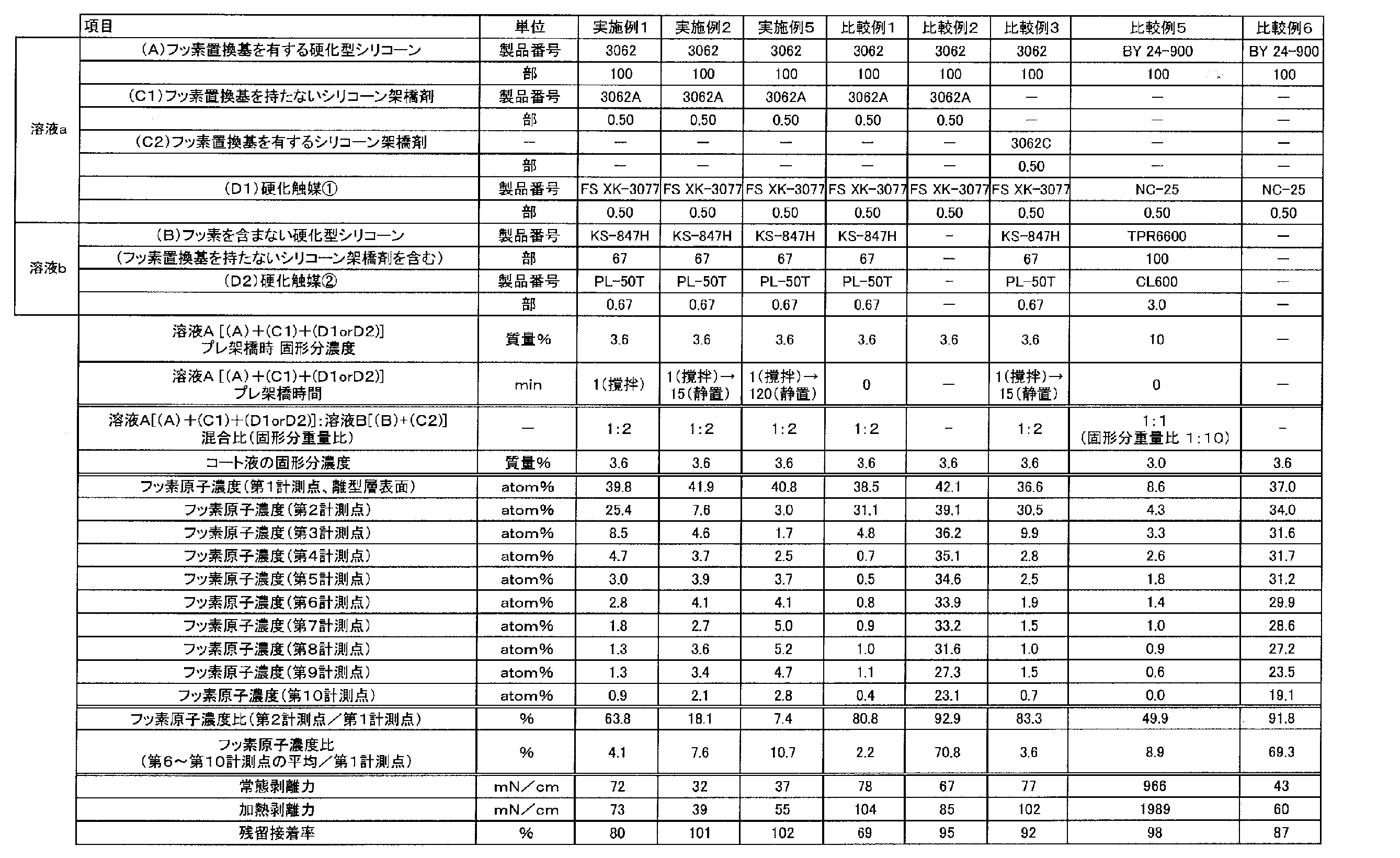
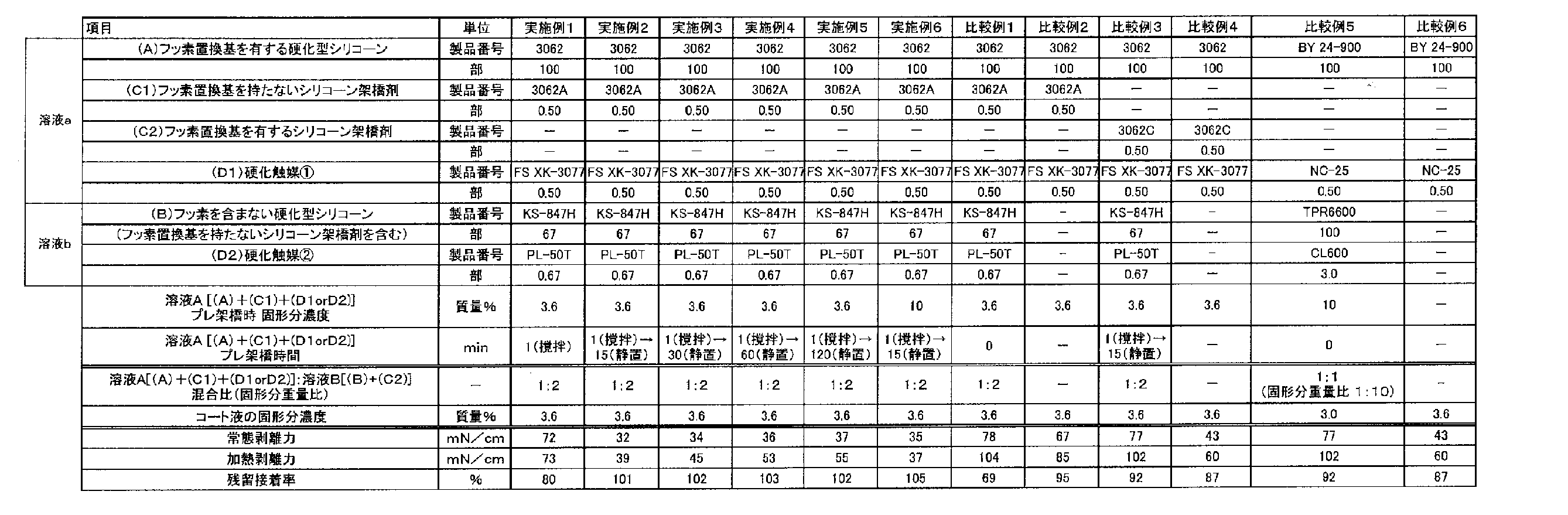
上記実施例及びこれまで本発明者が行ってきた試験結果から、基材フィルムの少なくとも片面側に形成する離型層が、(A)フッ素置換基を有する硬化型シリコーン、(B)フッ素置換基を含まない硬化型シリコーン、及び、(D)硬化触媒を含む離型層組成物が硬化してなるものは、フッ素化シリコーンの使用量を減らしても、シリコーン粘着剤層に対して剥離し易い優れた軽剥離性を有することが分かった。
しかも、そのような離型層の共通点を調査すると、当該離型層内の厚み方向におけるフッ素原子の濃度分布において、フッ素が離型層表面に偏在している特徴を見いだすことができた。
より具体的には、上記実施例のようにして得られたフッ素原子濃度分布(縦軸:フッ素原子濃度(atom%)、横軸:スパッタ時間(min))において、総スパッタ時間で均等に9分割して、第1計測点(スパッタ時間0)、第2計測点、・・第10計測点を決めた際、第2計測点~第10計測点におけるフッ素原子濃度(atom%)が、第1計測点(スパッタ時間0)におけるフッ素原子濃度(atom%)の80.0%以下であるという特徴を見出すことができた。
さらに、第6計測点~第10計測点における平均フッ素原子濃度(atom%)は、第1計測点(スパッタ時間0)におけるフッ素原子濃度(atom%)の2.2%より高ければ、さらに優れた効果、すなわち、フッ素化シリコーンの使用量を減らしても、シリコーン粘着剤層に対して剥離し易い優れた軽剥離性を得ることができることが分かった。
(A)フッ素置換基を有する硬化型シリコーンと(B)フッ素置換基を含まない硬化型シリコーンとの2種類を混合した溶液をフィルム上に塗布・乾燥した場合、より高疎水性である(A)フッ素置換基を有する硬化型シリコーンが表面(空気界面)側に偏析し易いことが確認された。
その一方、併用されるシリコーン架橋剤や触媒については、その分子構造から、(A)フッ素置換基を有する硬化型シリコーンと同水準の高疎水性を有していない。そのため、膜中で均一に分散せず、良好な硬化状態を有する離型層が得られなかったり、(B)フッ素置換基を含まない硬化型シリコーンを多く混合することができなかったりした。
そこで本発明では、先ず、(A)フッ素置換基を有する硬化型シリコーン、(C)シリコーン架橋剤及び(D)硬化触媒を混合し、攪拌および/または静置を行って反応させる“事前処理”を行い、該事前処理で得られた事前処理組成物と、(B)フッ素置換基を持たない硬化型シリコーンとを混合して離型層組成物を調製したところ、(C1)フッ素置換基を有さないシリコーン架橋剤を使用しても、均一に分散することができ、且つ、シリコーン粘着剤に対してより剥離し易い(軽剥離性)塗膜形成を実現することができることが分かった。
このメカニズム詳細は不明であるが、配合液作製後、経時変化において、配合液中で、適度な絡み合い(プレ架橋)が起こっているものと推察される。それに伴い、(A)フッ素置換基を有する硬化型シリコーンが表面(空気界面)側により多く存在しようとするものと推察される。
その結果、フィルムに塗布した後も、フッ素置換基が離型層表面近傍により多く偏在することで、軽剥離な特性を有する塗膜形成が可能になったものと推察される。
さらには、より多くの(B)フッ素置換基を含まない硬化型シリコーンを混合することができるため、離型層皮膜を形成する過程において、皮膜中におけるフッ素原子含有量の合計量をさらに低減することが可能となり、効率よく、離型性を発現できることもわかった。
Claims (26)
- 基材フィルムの少なくとも片面側に、(A)フッ素置換基を有する硬化型シリコーン、(B)フッ素置換基を含まない硬化型シリコーン、及び、(D)硬化触媒を含む離型層組成物が硬化してなる離型層を備えた離型フィルムであり、
当該離型層内の厚み方向におけるフッ素原子の濃度分布において、離型層表面にフッ素原子が偏在しており、離型層表面のフッ素原子濃度が39.0原子濃度%以上であることを特徴とする離型フィルム。 - XPS(X線光電子分光法)にGC-IB(ガスクラスターイオンビーム)を用いて、スパッタ速度一定下において、前記離型層内の厚み方向におけるフッ素原子の濃度分布を測定し、得られたフッ素原子濃度分布(縦軸:フッ素原子濃度(atom%)、横軸:スパッタ時間(min))を、総スパッタ時間で均等に9分割して、第1計測点(スパッタ時間0)、第2計測点、・・第10計測点を決めた際、
第2計測点~第10計測点におけるフッ素原子濃度(atom%)が、第1計測点(スパッタ時間0)におけるフッ素原子濃度(atom%)の80.0%以下であることを特徴とする離型フィルム。 - XPS(X線光電子分光法)にGC-IB(ガスクラスターイオンビーム)を用いて、スパッタ速度一定下において、前記離型層内の厚み方向におけるフッ素原子の濃度分布を測定し、得られたフッ素原子濃度分布(縦軸:フッ素原子濃度(atom%)、横軸:スパッタ時間(min))を、総スパッタ時間で均等に9分割して、第1計測点(スパッタ時間0)、第2計測点、・・第10計測点を決めた際、
第6計測点~第10計測点における平均フッ素原子濃度(atom%)が、第1計測点(スパッタ時間0)におけるフッ素原子濃度(atom%)の2.2%より高いことを特徴とする離型フィルム。 - 基材フィルムの少なくとも片面側に、(A)フッ素置換基を有する硬化型シリコーン、(B)フッ素置換基を含まない硬化型シリコーン、及び、(D)硬化触媒を含む離型層組成物が硬化してなる離型層を備えた離型フィルムである、請求項2または3に記載の離型フィルム。
- 前記離型層組成物が(C)シリコーン架橋剤を含む、請求項1又は4に記載の離型フィルム。
- (C)シリコーン架橋剤は、フッ素置換基を含まないシリコーン架橋剤であることを特徴とする請求項5に記載の離型フィルム。
- (A)フッ素置換基を有する前記硬化型シリコーンと、(B)フッ素置換基を含まない前記硬化型シリコーンとの質量比が1:50~10:1である、請求項1、4、5及び6のうちの何れかに記載の離型フィルム。
- 前記離型層におけるフッ素原子含有量が500質量ppm以上800000質量ppm以下である請求項1~7の何れかに記載の離型フィルム。
- (B)フッ素置換基を含まない硬化型シリコーンは、溶剤型硬化型シリコーンである請求項1、4、5、6、7及び8のうちの何れかに記載の離型フィルム。
- 前記離型層の常態剥離力は75mN/cm以下であり、かつ、残留接着率が80%以上である請求項1~9の何れかに記載の離型フィルム。
- 前記離型層の加熱剥離力が100mN/cm以下である請求項1~10の何れかに記載の離型フィルム。
- (A)フッ素置換基を有する硬化型シリコーン、(C)シリコーン架橋剤、及び(D)硬化触媒を混合した後、攪拌および/または静置を行い、次に、(B)フッ素置換基を持たない硬化型シリコーンと混合して離型層組成物を調製し、この離型層組成物を基材フィルムの少なくとも片面側に塗布することを特徴とする、離型フィルムの製造方法。
- (A)フッ素置換基を有する硬化型シリコーン、(C)シリコーン架橋剤、及び(D)硬化触媒を混合した後、攪拌および/または静置を1分以上行い、次に、(B)フッ素置換基を持たない硬化型シリコーンと混合して離型層組成物を調製し、この離型層組成物を基材フィルムの少なくとも片面側に塗布することを特徴とする、離型フィルムの製造方法。
- (C)シリコーン架橋剤として、フッ素置換基を含まないシリコーン架橋剤を用いることを特徴とする請求項12又は13に記載の離型フィルムの製造方法。
- 請求項1~11の何れかに記載の離型フィルムが、シリコーン粘着剤層を介して、機能層を備えた積層フィルムと貼り合わされてなる構成を備えたフィルム積層体。
- 機能層を有する前記積層フィルムが、基材フィルムの少なくとも片面側に、架橋樹脂層を設けた積層フィルムである、請求項15に記載のフィルム積層体。
- 前記架橋樹脂層が、導電性ポリマーおよびバインダーポリマーを含有する請求項16に記載のフィルム積層体。
- 機能層を有する前記積層フィルムが、基材フィルムの片面側に他の離型層を備えた離型フィルムである、請求項15に記載のフィルム積層体。
- 前記他の離型層が、(B)フッ素置換基を含まない硬化型シリコーンを主成分として含有するシリコーン組成物から形成される第1層、フッ素置換基を有する成分を含有する第2層を順次備えた構成からなる、請求項18に記載のフィルム積層体。
- 前記他の離型層が、(A)フッ素置換基を含有する硬化型シリコーンを主成分として含有するシリコーン組成物から形成される、請求項18に記載のフィルム積層体。
- 前記他の離型層が、(B)フッ素置換基を含まない硬化型シリコーンを主成分として含有するシリコーン組成物から形成される、請求項18に記載のフィルム積層体。
- 車載用部材の貼り合わせに用いることを特徴とする請求項15~21の何れかに記載のフィルム積層体。
- 請求項1~11の何れかに記載の離型フィルム(「軽剥離フィルム」と称する)を、シリコーン粘着剤からなるシリコーン粘着剤層の一側に積層し、当該シリコーン粘着剤層の他側には、前記離型フィルムよりも剥離強度が高い離型フィルム(「重剥離フィルム」と称する)を積層してなる構成を備えたフィルム積層体において、前記軽剥離フィルムを剥がした後、露出したシリコーン粘着剤層表面を被着体に貼着させ、該シリコーン粘着剤層を硬化させた後、前記重剥離フィルムを剥離することを特徴とするフィルム積層体の使用方法。
- 前記被着体が光学部材であることを特徴とする請求項23に記載のフィルム積層体の使用方法。
- 前記光学部材が偏光板又はタッチセンサーである請求項24に記載のフィルム積層体の使用方法。
- 前記光学部材が車載用光学部材であることを特徴とする請求項24又は25に記載のフィルム積層体。
Priority Applications (5)
| Application Number | Priority Date | Filing Date | Title |
|---|---|---|---|
| EP20846167.3A EP4005792A4 (en) | 2019-07-29 | 2020-04-14 | MOLD RELEASE FILM, FILM LAMINATE, METHOD OF MAKING A MOLD RELEASE FILM AND METHOD OF MANUFACTURING A FILM LAMINATE |
| CN202080041368.6A CN113939401A (zh) | 2019-07-29 | 2020-04-14 | 脱模薄膜、薄膜层叠体、它们的制造方法 |
| JP2021536610A JPWO2021019845A1 (ja) | 2019-07-29 | 2020-04-14 | |
| KR1020227006603A KR20220041172A (ko) | 2019-07-29 | 2020-04-14 | 이형 필름, 필름 적층체, 이들의 제조 방법 |
| US17/582,487 US20220143877A1 (en) | 2019-07-29 | 2022-01-24 | Mold release film, film laminate, method for producing mold release film, and method for producing film laminate |
Applications Claiming Priority (2)
| Application Number | Priority Date | Filing Date | Title |
|---|---|---|---|
| JP2019138531 | 2019-07-29 | ||
| JP2019-138531 | 2019-07-29 |
Related Child Applications (1)
| Application Number | Title | Priority Date | Filing Date |
|---|---|---|---|
| US17/582,487 Continuation US20220143877A1 (en) | 2019-07-29 | 2022-01-24 | Mold release film, film laminate, method for producing mold release film, and method for producing film laminate |
Publications (1)
| Publication Number | Publication Date |
|---|---|
| WO2021019845A1 true WO2021019845A1 (ja) | 2021-02-04 |
Family
ID=74228924
Family Applications (1)
| Application Number | Title | Priority Date | Filing Date |
|---|---|---|---|
| PCT/JP2020/016391 WO2021019845A1 (ja) | 2019-07-29 | 2020-04-14 | 離型フィルム、フィルム積層体、これらの製造方法 |
Country Status (7)
| Country | Link |
|---|---|
| US (1) | US20220143877A1 (ja) |
| EP (1) | EP4005792A4 (ja) |
| JP (1) | JPWO2021019845A1 (ja) |
| KR (1) | KR20220041172A (ja) |
| CN (1) | CN113939401A (ja) |
| TW (1) | TW202118629A (ja) |
| WO (1) | WO2021019845A1 (ja) |
Cited By (2)
| Publication number | Priority date | Publication date | Assignee | Title |
|---|---|---|---|---|
| CN115397939A (zh) * | 2021-03-05 | 2022-11-25 | 东丽尖端素材株式会社 | 离型膜 |
| KR20230032702A (ko) * | 2021-08-31 | 2023-03-07 | 도레이첨단소재 주식회사 | 레이저 타발공정용 필름 및 이를 포함하는 디스플레이 소자 |
Families Citing this family (3)
| Publication number | Priority date | Publication date | Assignee | Title |
|---|---|---|---|---|
| KR102633749B1 (ko) * | 2022-05-03 | 2024-02-05 | 도레이첨단소재 주식회사 | 이형필름 및 이의 제조방법 |
| KR102560126B1 (ko) * | 2022-05-03 | 2023-07-26 | 도레이첨단소재 주식회사 | 이형필름 및 이의 제조방법 |
| KR102639732B1 (ko) * | 2022-05-25 | 2024-02-23 | 도레이첨단소재 주식회사 | 이형필름 및 이의 제조방법 |
Citations (10)
| Publication number | Priority date | Publication date | Assignee | Title |
|---|---|---|---|---|
| JPH01313521A (ja) | 1988-04-22 | 1989-12-19 | Bayer Ag | ポリチオフエンの製造法 |
| EP0602731A2 (en) | 1992-12-14 | 1994-06-22 | International Business Machines Corporation | Disk cartridge |
| JPH06295016A (ja) | 1992-12-17 | 1994-10-21 | Agfa Gevaert Nv | 永久帯電防止プライマー層 |
| JPH07292081A (ja) | 1994-04-27 | 1995-11-07 | Natl Sci Council | 可溶性で加工可能なドープされた導電性ポリマーおよびその導電性ポリマーブレンド |
| JP2000006324A (ja) | 1998-06-19 | 2000-01-11 | Dainippon Printing Co Ltd | 積層体 |
| JP2011201035A (ja) | 2010-03-24 | 2011-10-13 | Shin Etsu Polymer Co Ltd | 離型用フィルム |
| JP2013510921A (ja) * | 2009-11-16 | 2013-03-28 | スリーエム イノベイティブ プロパティズ カンパニー | フルオロシリコーン配合剥離剤材料 |
| JP2015183041A (ja) * | 2014-03-20 | 2015-10-22 | 積水化学工業株式会社 | シリコーン粘着剤用離型フィルム |
| WO2016152992A1 (ja) * | 2015-03-26 | 2016-09-29 | 信越化学工業株式会社 | シリコーン粘着剤用剥離剤組成物、剥離フィルム及び積層体 |
| WO2019117059A1 (ja) * | 2017-12-11 | 2019-06-20 | 三菱ケミカル株式会社 | 積層フィルム、離型フィルムおよび積層体 |
Family Cites Families (2)
| Publication number | Priority date | Publication date | Assignee | Title |
|---|---|---|---|---|
| JP6481646B2 (ja) * | 2016-03-17 | 2019-03-13 | 信越化学工業株式会社 | 両面異差剥離紙又は両面異差剥離フィルム |
| JP6973054B2 (ja) * | 2017-12-27 | 2021-11-24 | 東洋紡株式会社 | セラミックグリーンシート製造用離型フィルム |
-
2020
- 2020-04-14 WO PCT/JP2020/016391 patent/WO2021019845A1/ja unknown
- 2020-04-14 EP EP20846167.3A patent/EP4005792A4/en active Pending
- 2020-04-14 KR KR1020227006603A patent/KR20220041172A/ko unknown
- 2020-04-14 CN CN202080041368.6A patent/CN113939401A/zh active Pending
- 2020-04-14 JP JP2021536610A patent/JPWO2021019845A1/ja active Pending
- 2020-04-23 TW TW109113629A patent/TW202118629A/zh unknown
-
2022
- 2022-01-24 US US17/582,487 patent/US20220143877A1/en active Pending
Patent Citations (11)
| Publication number | Priority date | Publication date | Assignee | Title |
|---|---|---|---|---|
| JPH01313521A (ja) | 1988-04-22 | 1989-12-19 | Bayer Ag | ポリチオフエンの製造法 |
| EP0602731A2 (en) | 1992-12-14 | 1994-06-22 | International Business Machines Corporation | Disk cartridge |
| JPH06295016A (ja) | 1992-12-17 | 1994-10-21 | Agfa Gevaert Nv | 永久帯電防止プライマー層 |
| US5391472A (en) | 1992-12-17 | 1995-02-21 | Agfa-Gevaert, N.V. | Permanent antistatic primer layer |
| JPH07292081A (ja) | 1994-04-27 | 1995-11-07 | Natl Sci Council | 可溶性で加工可能なドープされた導電性ポリマーおよびその導電性ポリマーブレンド |
| JP2000006324A (ja) | 1998-06-19 | 2000-01-11 | Dainippon Printing Co Ltd | 積層体 |
| JP2013510921A (ja) * | 2009-11-16 | 2013-03-28 | スリーエム イノベイティブ プロパティズ カンパニー | フルオロシリコーン配合剥離剤材料 |
| JP2011201035A (ja) | 2010-03-24 | 2011-10-13 | Shin Etsu Polymer Co Ltd | 離型用フィルム |
| JP2015183041A (ja) * | 2014-03-20 | 2015-10-22 | 積水化学工業株式会社 | シリコーン粘着剤用離型フィルム |
| WO2016152992A1 (ja) * | 2015-03-26 | 2016-09-29 | 信越化学工業株式会社 | シリコーン粘着剤用剥離剤組成物、剥離フィルム及び積層体 |
| WO2019117059A1 (ja) * | 2017-12-11 | 2019-06-20 | 三菱ケミカル株式会社 | 積層フィルム、離型フィルムおよび積層体 |
Non-Patent Citations (2)
| Title |
|---|
| "Latest Trends in Conductive Polymer Technology", 1 June 1999, TORAY RESEARCH CENTER, INC. |
| See also references of EP4005792A4 |
Cited By (3)
| Publication number | Priority date | Publication date | Assignee | Title |
|---|---|---|---|---|
| CN115397939A (zh) * | 2021-03-05 | 2022-11-25 | 东丽尖端素材株式会社 | 离型膜 |
| KR20230032702A (ko) * | 2021-08-31 | 2023-03-07 | 도레이첨단소재 주식회사 | 레이저 타발공정용 필름 및 이를 포함하는 디스플레이 소자 |
| KR102523093B1 (ko) * | 2021-08-31 | 2023-04-18 | 도레이첨단소재 주식회사 | 레이저 타발공정용 필름 및 이를 포함하는 디스플레이 소자 |
Also Published As
| Publication number | Publication date |
|---|---|
| JPWO2021019845A1 (ja) | 2021-02-04 |
| US20220143877A1 (en) | 2022-05-12 |
| EP4005792A1 (en) | 2022-06-01 |
| EP4005792A4 (en) | 2022-08-31 |
| KR20220041172A (ko) | 2022-03-31 |
| TW202118629A (zh) | 2021-05-16 |
| CN113939401A (zh) | 2022-01-14 |
Similar Documents
| Publication | Publication Date | Title |
|---|---|---|
| WO2021019845A1 (ja) | 離型フィルム、フィルム積層体、これらの製造方法 | |
| JP7234929B2 (ja) | 離型フィルム及び積層体 | |
| JP7314957B2 (ja) | 離型フィルム | |
| JP7031601B2 (ja) | 離型フィルム | |
| JP2008006750A (ja) | 離型フィルム | |
| WO2012090762A1 (ja) | 離型フィルム | |
| JP2022114930A (ja) | 離型層組成物、離型フィルムおよびこれらの製造方法、並びにフィルム積層体及びその使用方法 | |
| JP7173045B2 (ja) | 積層フィルム、離型フィルムおよび積層体 | |
| JP2022186742A (ja) | 離型フィルム | |
| JP2011011420A (ja) | 積層ポリエステルフィルム | |
| WO2016052171A1 (ja) | 積層フィルム、およびその製造方法 | |
| JP5728143B2 (ja) | 離型フィルム | |
| JP2024006000A (ja) | 離型層組成物、離型フィルムおよびこれらの製造方法、並びにフィルム積層体及びその使用方法 | |
| JP6364660B2 (ja) | 吸着フィルム | |
| JP2017164959A (ja) | 離型フィルム | |
| TWI840446B (zh) | 離型膜 | |
| JP6268875B2 (ja) | 離型フィルム | |
| JP2023135935A (ja) | 離型フィルム | |
| JP2022139376A (ja) | 離型フィルムおよびフィルム積層体 | |
| TW202413105A (zh) | 離型膜 |
Legal Events
| Date | Code | Title | Description |
|---|---|---|---|
| 121 | Ep: the epo has been informed by wipo that ep was designated in this application |
Ref document number: 20846167 Country of ref document: EP Kind code of ref document: A1 |
|
| ENP | Entry into the national phase |
Ref document number: 2021536610 Country of ref document: JP Kind code of ref document: A |
|
| NENP | Non-entry into the national phase |
Ref country code: DE |
|
| ENP | Entry into the national phase |
Ref document number: 20227006603 Country of ref document: KR Kind code of ref document: A |
|
| ENP | Entry into the national phase |
Ref document number: 2020846167 Country of ref document: EP Effective date: 20220228 |