WO2021019822A1 - 成形品 - Google Patents
成形品 Download PDFInfo
- Publication number
- WO2021019822A1 WO2021019822A1 PCT/JP2020/010948 JP2020010948W WO2021019822A1 WO 2021019822 A1 WO2021019822 A1 WO 2021019822A1 JP 2020010948 W JP2020010948 W JP 2020010948W WO 2021019822 A1 WO2021019822 A1 WO 2021019822A1
- Authority
- WO
- WIPO (PCT)
- Prior art keywords
- light
- resin member
- molded product
- front side
- back side
- Prior art date
Links
Images


Classifications
-
- B—PERFORMING OPERATIONS; TRANSPORTING
- B29—WORKING OF PLASTICS; WORKING OF SUBSTANCES IN A PLASTIC STATE IN GENERAL
- B29C—SHAPING OR JOINING OF PLASTICS; SHAPING OF MATERIAL IN A PLASTIC STATE, NOT OTHERWISE PROVIDED FOR; AFTER-TREATMENT OF THE SHAPED PRODUCTS, e.g. REPAIRING
- B29C33/00—Moulds or cores; Details thereof or accessories therefor
- B29C33/42—Moulds or cores; Details thereof or accessories therefor characterised by the shape of the moulding surface, e.g. ribs or grooves
-
- G—PHYSICS
- G09—EDUCATION; CRYPTOGRAPHY; DISPLAY; ADVERTISING; SEALS
- G09F—DISPLAYING; ADVERTISING; SIGNS; LABELS OR NAME-PLATES; SEALS
- G09F13/00—Illuminated signs; Luminous advertising
- G09F13/04—Signs, boards or panels, illuminated from behind the insignia
- G09F13/08—Signs, boards or panels, illuminated from behind the insignia using both translucent and non-translucent layers
-
- B—PERFORMING OPERATIONS; TRANSPORTING
- B29—WORKING OF PLASTICS; WORKING OF SUBSTANCES IN A PLASTIC STATE IN GENERAL
- B29C—SHAPING OR JOINING OF PLASTICS; SHAPING OF MATERIAL IN A PLASTIC STATE, NOT OTHERWISE PROVIDED FOR; AFTER-TREATMENT OF THE SHAPED PRODUCTS, e.g. REPAIRING
- B29C45/00—Injection moulding, i.e. forcing the required volume of moulding material through a nozzle into a closed mould; Apparatus therefor
- B29C45/16—Making multilayered or multicoloured articles
-
- B—PERFORMING OPERATIONS; TRANSPORTING
- B60—VEHICLES IN GENERAL
- B60R—VEHICLES, VEHICLE FITTINGS, OR VEHICLE PARTS, NOT OTHERWISE PROVIDED FOR
- B60R13/00—Elements for body-finishing, identifying, or decorating; Arrangements or adaptations for advertising purposes
- B60R13/02—Internal Trim mouldings ; Internal Ledges; Wall liners for passenger compartments; Roof liners
-
- G—PHYSICS
- G09—EDUCATION; CRYPTOGRAPHY; DISPLAY; ADVERTISING; SEALS
- G09F—DISPLAYING; ADVERTISING; SIGNS; LABELS OR NAME-PLATES; SEALS
- G09F13/00—Illuminated signs; Luminous advertising
- G09F13/04—Signs, boards or panels, illuminated from behind the insignia
- G09F13/06—Signs, boards or panels, illuminated from behind the insignia using individual cut-out symbols or cut-out silhouettes, e.g. perforated signs
-
- G—PHYSICS
- G09—EDUCATION; CRYPTOGRAPHY; DISPLAY; ADVERTISING; SEALS
- G09F—DISPLAYING; ADVERTISING; SIGNS; LABELS OR NAME-PLATES; SEALS
- G09F21/00—Mobile visual advertising
- G09F21/04—Mobile visual advertising by land vehicles
- G09F21/049—Mobile visual advertising by land vehicles giving information to passengers inside the vehicles
-
- B—PERFORMING OPERATIONS; TRANSPORTING
- B29—WORKING OF PLASTICS; WORKING OF SUBSTANCES IN A PLASTIC STATE IN GENERAL
- B29K—INDEXING SCHEME ASSOCIATED WITH SUBCLASSES B29B, B29C OR B29D, RELATING TO MOULDING MATERIALS OR TO MATERIALS FOR MOULDS, REINFORCEMENTS, FILLERS OR PREFORMED PARTS, e.g. INSERTS
- B29K2995/00—Properties of moulding materials, reinforcements, fillers, preformed parts or moulds
- B29K2995/0018—Properties of moulding materials, reinforcements, fillers, preformed parts or moulds having particular optical properties, e.g. fluorescent or phosphorescent
- B29K2995/0025—Opaque
-
- B—PERFORMING OPERATIONS; TRANSPORTING
- B29—WORKING OF PLASTICS; WORKING OF SUBSTANCES IN A PLASTIC STATE IN GENERAL
- B29K—INDEXING SCHEME ASSOCIATED WITH SUBCLASSES B29B, B29C OR B29D, RELATING TO MOULDING MATERIALS OR TO MATERIALS FOR MOULDS, REINFORCEMENTS, FILLERS OR PREFORMED PARTS, e.g. INSERTS
- B29K2995/00—Properties of moulding materials, reinforcements, fillers, preformed parts or moulds
- B29K2995/0018—Properties of moulding materials, reinforcements, fillers, preformed parts or moulds having particular optical properties, e.g. fluorescent or phosphorescent
- B29K2995/0026—Transparent
Definitions
- the present invention relates to a molded product.
- a transparent resin member having a certain thickness is provided on the design surface so as to present a visual sense of depth up to the design surface.
- Technology is being used.
- Patent Document 1 a two-color molded decorative product having a sense of depth is formed by providing an insert sheet having a decorative layer between the primary molding resin and the transparent secondary molding resin. The technology is disclosed.
- the molded product of one embodiment is a molded product that displays an optical image that can be seen from the front side by transmitting light emitted from a light source provided on the back side, and has a shape corresponding to the light image in a plan view.
- the member has a peripheral portion having a certain thickness and a thin portion which is provided inside the peripheral portion and is thinner than the peripheral portion.
- a molded product capable of obtaining a visual sense of depth and suppressing the occurrence of various defects during molding.
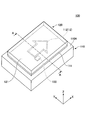
- FIG. 1 is an external perspective view of a molded product 100 according to an embodiment.
- the molded product 100 shown in FIG. 1 is transmitted from the front side (Z-axis positive side) by transmitting light emitted from a light source 130 (for example, LED (light emitting diode)) provided on the back side (Z-axis negative side).
- a light source 130 for example, LED (light emitting diode)
- the molded product 100 is used for an interior part of an automobile (for example, a panel, a switch, etc.), and by displaying an optical image 12, the user is notified of an automobile function, a warning, or the like.
- the molded product 100 includes a light-shielding resin member 110 and a transparent resin member 120, and has a two-layer structure composed of the light-shielding resin member 110 and the transparent resin member 120.
- the light-shielding resin member 110 and the transparent resin member 120 are integrally formed by two-color molding.
- the light-shielding resin member 110 is a member having a light-shielding property.
- the light-shielding resin member 110 has a substantially rectangular parallelepiped shape as a whole.
- the light-shielding resin member 110 has a panel portion 111 that is one step higher than the surroundings on the surface 110A, which is the front surface of the light-shielding resin member 110.
- the panel portion 111 is formed with a light transmission hole 112 capable of transmitting the light emitted from the light source 130 from the back side of the panel portion 111 to the front side of the panel portion 111.
- the light transmission hole 112 has a shape corresponding to the optical image 12 in a plan view from above (Z-axis positive direction).
- the light transmission hole 112 transmits the light emitted from the light source 130 provided on the back side (Z-axis negative side) of the panel portion 111 from the back side of the panel portion 111 to the front side of the panel portion 111, thereby transmitting the light of the panel portion 111.
- the optical image 12 that can be seen from the front side (the positive side of the Z axis) is displayed on the surface 111A of the panel unit 111.
- the arrow shape is used as an example of the shape of the light transmitting hole 112, but the light transmitting hole 112 is not limited to this, and any shape can be adopted depending on the use of the molded product 100.
- the light-shielding resin member 110 is formed by using a resin material having a light-shielding property.
- the light-shielding resin member 110 is formed by using a synthetic resin of PC (polycarbonate resin) and ABS resin, which is colored black, as an example of a resin material having light-shielding property.
- the light-shielding resin member 110 is entirely black and has light-shielding properties.
- the transmissive resin member 120 is a substantially flat member having light transmissibility.
- the transmissive resin member 120 is provided so as to overlap at least the light transmitting hole 112 on the front side (Z-axis positive side) of the panel portion 111 of the light-shielding resin member 110.
- the surface 121 which is the front surface (Z-axis positive side) of the permeable resin member 120, is a smooth flat surface.
- the permeable resin member 120 protects the surface of the panel portion 111 of the light-shielding resin member 110 and has a certain thickness, so that the molded product 100 is permeable when viewed from the front side (Z-axis positive side). The user can be presented with a visual sense of depth from the surface 121 of the resin member 120 to the surface of the panel portion 111.
- the transmissive resin member 120 is formed by using a resin material having light transmissibility.
- the transmissive resin member 120 is formed by using PC (polycarbonate resin) colored in a light gray smoke color as an example of a resin material having light transmissibility.
- the transparent resin member 120 has a smoke color and light transmission as a whole.
- the smoke color is not limited to the light gray of the present embodiment, but includes "color tone with suppressed visible light transmittance" in general, and the color tone and transmittance are arbitrarily selected to meet the visual requirements. It is possible.
- the light source 130 when the light source 130 is turned on by external control, the light emitted from the light source 130 passes through the light transmission hole 112 formed in the panel portion 111, whereby the panel portion The optical image 12 is displayed on 111.
- the optical image 12 displayed on the panel portion 111 is visually recognized by the user from the surface 121 of the transparent resin member 120 by transmitting through the transparent resin member 120.
- the optical image 12 is hidden in the panel unit 111.
- the transparent resin member 120 is colored in smoke color and the surface of the panel portion 111 is black, the transparent resin member is in a state where the optical image 12 is hidden.
- the light transmission hole 112 is difficult to see from the surface 121 of the 120. That is, for the user, the panel unit 111 on which the optical image 12 is displayed is in a state called a so-called black-out or secret-until-lit in which nothing is displayed.
- FIG. 2 is a cross-sectional view taken along the line AA of the molded product 100 shown in FIG.
- the light-shielding resin member 110 has a dome-shaped convex portion 113 on the surface 111A and the central portion of the panel portion 111.
- the light transmission hole 112 is formed in the convex portion 113.
- the permeable resin member 120 has a flat surface 121 on the front side (positive side of the Z axis) and is in close contact with the convex portion 113 at the center of the back surface 122 which is the surface on the back side (negative side of the Z axis).
- a curved concave portion 123 is formed.
- the permeable resin member 120 has a peripheral portion 120A having a certain thickness due to the formation of the recess 123, and a thin portion 120B provided inside the peripheral portion 120A and thinner than the peripheral portion 120A. It has become.
- the recess 123 has a curved surface shape, the thin portion 120B gradually becomes thinner toward the center of the recess 123.
- the permeable resin member 120 has a peripheral portion 120A having a certain thickness.
- the molded product 100 of the present embodiment gives a visual sense of depth from the surface 121 of the transparent resin member 120 to the surface 111A of the panel portion 111 when viewed from the front side (Z-axis positive side). , Can be presented to the user.
- the visual sense of depth is more clearly felt when the edge portion and the side surface portion 126 of the peripheral portion 120A of the transparent resin member 120 are viewed from the front side and the oblique direction. Therefore, in the molded product 100 of the present embodiment, by setting the peripheral portion 120A having the edge portion and the side surface portion 126 to a constant thickness, it is easy to feel a visual sense of depth.
- the surface 121 of the transparent resin member 120 is flat, it becomes difficult for the user to notice the change in thickness from the peripheral portion 120A even for the thin portion 120B. Therefore, it is possible to present the user with a sense of depth similar to that of the peripheral portion 120A.
- the permeable resin member 120 has a thin portion 120B.
- the molded product 100 of the present embodiment has a shorter cooling time during molding, a reduction in the amount of material used, and a sink mark, as compared with the conventional configuration in which the permeable resin member has a constant thickness as a whole. It is possible to exert effects such as suppressing the amount of generation of. Therefore, according to the molded product 100 of the present embodiment, it is possible to obtain a visual sense of depth and suppress the occurrence of various defects during molding.
- the permeable resin member 120 is a primary molded part formed by using a primary mold.
- the light-shielding resin member 110 is a secondary molded part formed so as to be overlapped with the transparent resin member 120 by using a secondary mold.
- the transparent resin member 120 since the transparent resin member 120 is used as a primary molded part, the transparent resin member 120 can be molded independently, so that the degree of freedom in the molding conditions of the transparent resin member 120 can be increased. Can be enhanced. Therefore, the molded product 100 of the present embodiment can suppress the occurrence of sink marks and the like during molding of the transparent resin member 120, and can improve the appearance quality of the transparent resin member 120.
- the transparent resin member 120 is formed by using a smoke-colored resin material
- the light-shielding resin member 110 is formed by using a black resin material.
- a gate portion 125 generated during molding of the transparent resin member 120 is left in the peripheral portion 120A on the back surface 122 of the transparent resin member 120.
- the gate portion 125 is covered with the light-shielding resin member 110.
- the transparent resin member 120 has a smoke color. Therefore, the gate portion 125 is difficult to see from the front side of the molded product 100. Therefore, in the molded product 100 of the present embodiment, the gate portion 125 may be left largely, that is, the degree of freedom in designing the gate portion 125 in the manufacturing process of the molded product 100 is increased, and the gate portion 125 is increased. Removal step can be omitted.
- the light transmission hole 112 is formed in the convex portion 113 of the panel portion 111. That is, the light transmission hole 112 is formed in the panel portion 111 at a position facing the back surface of the thin portion 120B of the transparent resin member 120.
- the molded product 100 of the present embodiment when the molded product 100 is viewed from the front side and from an oblique direction, light is refracted by the refractive index of the transparent resin member 120, and the optical image 12 deviates from the actual position.
- the phenomenon of appearing in a vertical position can be alleviated by reducing the thickness of the molded product at the refracting portion.
- FIG. 3 is a partially enlarged view of the molded product 100 shown in FIG.
- the light transmission holes 112 are formed on the front side opening 112A formed on the front side (Z-axis positive side) of the boundary position P1 and on the back side (Z-axis negative side) of the boundary position P1. It is configured to have a back side opening 112B.
- the permeable resin member 120 is formed by using a smoke-colored resin material
- the light-shielding resin member 110 is formed by using a black resin material.
- the front side opening 112A has a front side inclined surface 112Aa.
- the front side inclined surface 112Aa is inclined toward the outside toward the front side (Z-axis positive side).
- the front side opening 112A has a trapezoidal cross-sectional shape in which the opening width gradually increases toward the front side (Z-axis positive side).
- the back side opening 112B has a back side inclined surface 112Ba.
- the back side inclined surface 112Ba is inclined so as to be outward toward the back side (Z-axis negative side).
- the back side opening 112B has a trapezoidal cross-sectional shape in which the opening width gradually increases toward the back side (Z-axis negative side).
- the back side opening 112B is an air layer, but the present invention is not limited to this, and a light diffusing member 140 (see FIG. 2) that diffuses light is fitted into the back side opening 112B from the back side. You may.
- the light diffusing member 140 may be formed in a state of being fitted into the back side opening 112B by three-color molding, or may be formed by another molding method and then fitted into the back side opening 112B. Good.
- the light diffusing member 140 is formed by using a PC resin material or an acrylic resin material containing silicon beads.
- the front side opening 112A and the back side opening 112B are formed when the light-shielding resin member 110 is molded. Since the resin material easily flows into both of the above and the above, for example, the rounding (short mold) of the edge portion 112C formed at the boundary position P1 of the light transmission hole 112 can be suppressed.
- the minimum opening width W2 of the back side opening 112B (that is, the opening width W2 at the boundary position P1) is the minimum opening width W1 of the front side opening 112A (that is, the opening width W1 at the boundary position P1). ) Is larger than. That is, as shown by an arrow in FIG. 3, the back side inclined surface 112Ba of the back side opening 112B is offset to the outside in the opening width direction with respect to the front side inclined surface 112Aa of the front side opening 112A. As a result, a sharp edge portion 112C is formed at the boundary position P1 of the light transmission hole 112.
- the molded product 100 of the present embodiment has the refractive index of the transparent resin member 120 (for example, 1.59 in the case of PC) and the refractive index of the air layer when the molded product 100 is viewed from the front side. It is possible to prevent the back side inclined surface 112Ba of the back side opening 112B from being visually recognized even when the light is refracted at the boundary position P1. Therefore, in the molded product 100 of the present embodiment, it is possible to prevent the edge portion 112C of the light transmission hole 112 from appearing blurry due to the back side inclined surface 112Ba.
- the present invention can be used for interior parts for vehicles, but the present invention is not limited to this, and the present invention can be used for molded products for any purpose.
- the present invention is not limited to a molded product in which the surface of the light-shielding resin member is black.
- the surface of the light-shielding resin member is decorated with a decorative layer (for example, a decorative sheet). It can also be used for molded products.
- the present invention is not limited to a molded product in which the transparent resin member is colored in smoke color, and for example, the present invention is also used in a molded product in which the transparent resin member is colored colorless or in a color other than smoke color. It is possible.
Landscapes
- Engineering & Computer Science (AREA)
- Mechanical Engineering (AREA)
- Physics & Mathematics (AREA)
- Theoretical Computer Science (AREA)
- General Physics & Mathematics (AREA)
- Manufacturing & Machinery (AREA)
- Business, Economics & Management (AREA)
- Marketing (AREA)
- Accounting & Taxation (AREA)
- Injection Moulding Of Plastics Or The Like (AREA)
- Laminated Bodies (AREA)
- Illuminated Signs And Luminous Advertising (AREA)
- Moulds For Moulding Plastics Or The Like (AREA)
Abstract
成形品は、裏側に設けられた光源から照射された光を透過することによって、表側から視認可能な光画像を表示する成形品であって、平面視において光画像に応じた形状の光透過孔を有する遮光性樹脂部材と、遮光性樹脂部材の表側の面に少なくとも光透過孔を覆うように重ねて設けられ、光透過性を有する透過性樹脂部材とを備え、透過性樹脂部材は、一定の厚さを有する周辺部と、周辺部の内側に設けられ、周辺部よりも薄厚の薄厚部とを有する。
Description
本発明は、成形品に関する。
従来、自動車の内装部品等に用いられる樹脂製の成形品において、一定の厚みを有する透明な樹脂部材を意匠面に重ねて設けることにより、意匠面に至るまでの視覚的な奥行き感を呈示する技術が利用されている。
例えば、下記特許文献1には、1次成形樹脂と透明な2次成形樹脂との間に加飾層を備えたインサートシートを設けることにより、深み感を備えた2色成形加飾品を形成する技術が開示されている。
しかしながら、上記特許文献1の技術では、2次成形樹脂の厚さが一定であるために、例えば、成形時における冷却時間の増加、材料の使用量の増加、ヒケの発生量の増加、等の各種不具合が生じる虞がある。
一実施形態の成形品は、裏側に設けられた光源から照射された光を透過することによって、表側から視認可能な光画像を表示する成形品であって、平面視において光画像に応じた形状の光透過孔を有する遮光性樹脂部材と、遮光性樹脂部材の表側の面に少なくとも光透過孔を覆うように重ねて設けられ、光透過性を有する透過性樹脂部材とを備え、透過性樹脂部材は、一定の厚さを有する周辺部と、周辺部の内側に設けられ、周辺部よりも薄厚の薄厚部とを有する。
一実施形態によれば、視覚的な奥行き感を得ることができ、且つ、成型時における各種不具合の発生を抑制することが可能な成形品を提供することができる。
以下、図面を参照して、一実施形態について説明する。
(成形品100の概要)
図1は、一実施形態に係る成形品100の外観斜視図である。図1に示す成形品100は、裏側(Z軸負側)に設けられる光源130(例えば、LED(light emitting diode))から照射された光を透過することによって、表側(Z軸正側)から視認可能な光画像12を表示する成形品である。例えば、成形品100は、自動車の内装部品(例えば、パネル、スイッチ等)に用いられ、光画像12を表示することによって、自動車の機能や警告等をユーザに通知する。
図1は、一実施形態に係る成形品100の外観斜視図である。図1に示す成形品100は、裏側(Z軸負側)に設けられる光源130(例えば、LED(light emitting diode))から照射された光を透過することによって、表側(Z軸正側)から視認可能な光画像12を表示する成形品である。例えば、成形品100は、自動車の内装部品(例えば、パネル、スイッチ等)に用いられ、光画像12を表示することによって、自動車の機能や警告等をユーザに通知する。
図1に示すように、成形品100は、遮光性樹脂部材110および透過性樹脂部材120を備えており、遮光性樹脂部材110および透過性樹脂部材120による2層構造を有する。成形品100は、2色成形により、遮光性樹脂部材110と透過性樹脂部材120とが一体的に形成される。
遮光性樹脂部材110は、遮光性を有する部材である。図1に示す例では、遮光性樹脂部材110は、全体的に概ね直方体形状を有する。図1に示すように、遮光性樹脂部材110は、当該遮光性樹脂部材110の表側の面である表面110Aに、周囲よりも一段高められたパネル部111を有する。パネル部111には、光源130から照射された光をパネル部111の裏側からパネル部111の表側に透過させることが可能な、光透過孔112が形成されている。光透過孔112は、上方(Z軸正方向)からの平面視において光画像12に応じた形状を有する。
光透過孔112は、パネル部111の裏側(Z軸負側)に設けられる光源130から照射された光を、パネル部111の裏側からパネル部111の表側に透過することにより、パネル部111の表側(Z軸正側)から視認可能な光画像12を、パネル部111の表面111Aに表示する。本実施形態では、光透過孔112の形状の一例として矢印形状を用いているが、これに限らず、光透過孔112は、成形品100の用途に応じて任意の形状が採用され得る。
遮光性樹脂部材110は、遮光性を有する樹脂素材が用いられて形成される。本実施形態では、遮光性樹脂部材110は、遮光性を有する樹脂素材の一例として、黒色に着色された、PC(ポリカーボネート樹脂)とABS樹脂との合成樹脂が用いられて形成される。これにより、遮光性樹脂部材110は、全体的に黒色且つ遮光性を有する。
透過性樹脂部材120は、光透過性を有する概ね平板状の部材である。透過性樹脂部材120は、遮光性樹脂部材110のパネル部111の表側(Z軸正側)の面に少なくとも光透過孔112を覆うように重ねて設けられる。透過性樹脂部材120の表側(Z軸正側)の面である表面121は、平滑な平面である。透過性樹脂部材120は、遮光性樹脂部材110のパネル部111の表面を保護するとともに、ある程度の厚みを有することにより、成形品100を表側(Z軸正側)から見たときに、透過性樹脂部材120の表面121からパネル部111の表面までの視覚的な奥行き感を、ユーザに呈示することができる。
透過性樹脂部材120は、光透過性を有する樹脂素材が用いられて形成される。本実施形態では、透過性樹脂部材120は、光透過性を有する樹脂素材の一例として、淡いグレーのスモーク色に着色された、PC(ポリカーボネート樹脂)が用いられて形成される。これにより、透過性樹脂部材120は、全体的にスモーク色且つ光透過性を有する。なお、スモーク色とは、本実施形態の淡いグレーに限るものではなく、「可視光透過率を抑えた色調」全般を含み、視覚的な要求に合うように、色調や透過率を任意に選択可能である。
このように構成された成形品100では、外部からのコントロールによって光源130が点灯すると、光源130から発せられた光が、パネル部111に形成された光透過孔112を透過することによって、パネル部111に光画像12が表示される。パネル部111に表示された光画像12は、透過性樹脂部材120を透過することにより、透過性樹脂部材120の表面121から、ユーザによって視認される。
一方、成形品100では、外部からのコントロールによって光源130が消灯すると、パネル部111において光画像12が非表示となる。本実施形態の成形品100は、透過性樹脂部材120がスモーク色に着色されており、且つ、パネル部111の表面が黒色であるため、光画像12が非表示の状態において、透過性樹脂部材120の表面121から、光透過孔112が視認され難くなっている。すなわち、ユーザにとっては、光画像12が表示されていたパネル部111が、何も表示されない、いわゆるブラックアウト(Black-out)もしくは、シークレットアンティルリット(Secret-until-lit)と呼ばれる状態となる。
(成形品100の構成)
図2は、図1に示す成形品100のA-A断面図である。図2に示すように、遮光性樹脂部材110は、パネル部111の表面111A且つ中央部に、ドーム状の凸部113を有する。パネル部111において、光透過孔112は、凸部113に形成されている。
図2は、図1に示す成形品100のA-A断面図である。図2に示すように、遮光性樹脂部材110は、パネル部111の表面111A且つ中央部に、ドーム状の凸部113を有する。パネル部111において、光透過孔112は、凸部113に形成されている。
また、透過性樹脂部材120は、表側(Z軸正側)の面である表面121が平面であり、裏側(Z軸負側)の面である裏面122の中央部に、凸部113と密着する曲面形状の凹部123が形成されている。透過性樹脂部材120は、凹部123が形成されたことによって、一定の厚さを有する周辺部120Aと、周辺部120Aの内側に設けられ、周辺部120Aよりも薄厚の薄厚部120Bとを有するものとなっている。特に、凹部123が曲面形状であるため、薄厚部120Bは、凹部123の中心に向うにつれて、徐々に厚さが薄くなる。
このように、本実施形態の成形品100は、透過性樹脂部材120が、一定の厚さを有する周辺部120Aを有する。これにより、本実施形態の成形品100は、表側(Z軸正側)から見たときに、透過性樹脂部材120の表面121からパネル部111の表面111Aに至るまでの視覚的な奥行き感を、ユーザに呈示することができる。本実施形態の成形品100において、視覚的な奥行き感は、透過性樹脂部材120の周辺部120Aのエッジ部分および側面部126を表側かつ斜め方向から見た場合により明確に感じられる。このため、本実施形態の成形品100では、このエッジ部分および側面部126を有する周辺部120Aを一定の厚さとすることで、視覚的な奥行き感が感じられ易くなっているのである。
特に、本実施形態の成形品100は、透過性樹脂部材120の表面121が平面であるため、薄厚部120Bに対しても、ユーザの錯覚により周辺部120Aからの厚さの変化に気づきにくくなるため、周辺部120Aと同様の奥行き感をユーザに呈示することができる。
また、本実施形態の成形品100は、透過性樹脂部材120が薄厚部120Bを有する。これにより、本実施形態の成形品100は、透過性樹脂部材が全体的に一定の厚さを有する従来の構成と比較して、成形時における冷却時間の短縮、材料の使用量の削減、ヒケの発生量の抑制、等の効果を奏することができる。したがって、本実施形態の成形品100によれば、視覚的な奥行き感を得ることができ、且つ、成型時における各種不具合の発生を抑制することができる。
ここで、透過性樹脂部材120は、一次金型を用いて形成される一次成型部品である。また、遮光性樹脂部材110は、二次金型を用いて、透過性樹脂部材120に対して重ねて形成される二次成型部品である。
本実施形態の成形品100は、透過性樹脂部材120を一次成型部品としたことにより、透過性樹脂部材120を単独で成形することができるため、透過性樹脂部材120の成形条件の自由度を高めることができる。このため、本実施形態の成形品100は、透過性樹脂部材120の成型時におけるヒケ等の発生を抑制し、透過性樹脂部材120の外観品質を高めることができる。
また、透過性樹脂部材120は、スモーク色の樹脂素材が用いられて形成されており、遮光性樹脂部材110は、黒色の樹脂素材が用いられて形成されている。これにより、本実施形態の成形品100は、比較的低コストで、光源130の消灯時に成形品100の表側から光透過孔112を見え難くすることができる。
また、図2に示すように、透過性樹脂部材120の裏面122における周辺部120Aには、透過性樹脂部材120の成形時に生じたゲート部125が残されている。但し、ゲート部125は、遮光性樹脂部材110によって覆われている。また、透過性樹脂部材120は、スモーク色である。このため、ゲート部125は、成形品100の表側から見え難くなっている。このため、本実施形態の成形品100は、ゲート部125が大きく残されたままであってもよく、すなわち、成形品100の製造過程におけるゲート部125の設計の自由度が上がるとともに、ゲート部125の除去工程を省くことができる。
また、図2に示すように、光透過孔112は、パネル部111における凸部113に形成されている。すなわち、光透過孔112は、パネル部111において、透過性樹脂部材120の薄厚部120Bの裏側の面と対向する位置に形成されている。これにより、本実施形態の成形品100は、当該成形品100を表側且つ斜め方向から見た場合に、透過性樹脂部材120の屈折率によって光が屈折し、光画像12が実際の位置からずれた位置に見えてしまうという現象を、屈折する部位の成形品の厚さを薄くすることによって軽減することができる。
(光透過孔112の詳細な形状)
図3は、図2に示す成形品100の一部拡大図である。図3に示すように、光透過孔112は、境界位置P1よりも表側(Z軸正側)に形成された表側開口部112Aと、境界位置P1よりも裏側(Z軸負側)に形成された裏側開口部112Bとを有して構成されている。透過性樹脂部材120は、スモーク色の樹脂素材が用いられて形成されており、遮光性樹脂部材110は、黒色の樹脂素材が用いられて形成されている。これにより、本実施形態の成形品100は、比較的低コストで、光源130の消灯時に成形品100の表側から光透過孔112の表側開口部112Aを見え難くすることができる。
図3は、図2に示す成形品100の一部拡大図である。図3に示すように、光透過孔112は、境界位置P1よりも表側(Z軸正側)に形成された表側開口部112Aと、境界位置P1よりも裏側(Z軸負側)に形成された裏側開口部112Bとを有して構成されている。透過性樹脂部材120は、スモーク色の樹脂素材が用いられて形成されており、遮光性樹脂部材110は、黒色の樹脂素材が用いられて形成されている。これにより、本実施形態の成形品100は、比較的低コストで、光源130の消灯時に成形品100の表側から光透過孔112の表側開口部112Aを見え難くすることができる。
表側開口部112Aは、表側傾斜面112Aaを有している。表側傾斜面112Aaは、表側(Z軸正側)に向うにつれて、外側に向うように傾斜している。これにより、表側開口部112Aは、表側(Z軸正側)に向って徐々に開口幅が拡大する台形の断面形状を有している。表側開口部112Aには、透過性樹脂部材120の凹部123に形成された、当該表側開口部112Aと同形状を有する凸部124が嵌め合わされている。
裏側開口部112Bは、裏側傾斜面112Baを有している。裏側傾斜面112Baは、裏側(Z軸負側)に向うにつれて、外側に向うように傾斜している。これにより、裏側開口部112Bは、裏側(Z軸負側)に向って徐々に開口幅が拡大する台形の断面形状を有している。
なお、本実施形態では、裏側開口部112Bは、空気層となっているが、これに限らず、光を拡散する光拡散部材140(図2参照)が、裏側開口部112Bに裏側から嵌め込まれてもよい。この場合、光拡散部材140は、3色成形によって裏側開口部112Bには嵌め込まれた状態に形成されてもよく、それ以外の成形方法によって形成された後、裏側開口部112Bに嵌め込まれてもよい。例えば、光拡散部材140は、シリコンビーズを含んだPC樹脂素材またはアクリル樹脂素材が用いられて形成される。
このように、本実施形態の成形品100は、光透過孔112が表側開口部112Aおよび裏側開口部112Bを有することにより、遮光性樹脂部材110の成形時に、表側開口部112Aと裏側開口部112Bとの双方に対して樹脂素材が流れ込み易く、このため、例えば、光透過孔112の境界位置P1に形成されるエッジ部112Cの丸まり(ショートモールド)を抑制することができる。
また、図3に示すように、裏側開口部112Bの最小開口幅W2(すなわち、境界位置P1における開口幅W2)は、表側開口部112Aの最小開口幅W1(すなわち、境界位置P1における開口幅W1)よりも大きくなっている。すなわち、図3において矢印で示されているように、裏側開口部112Bの裏側傾斜面112Baは、表側開口部112Aの表側傾斜面112Aaよりも開口幅方向外側にオフセットされている。これにより、光透過孔112の境界位置P1には、先鋭状のエッジ部112Cが形成されている。
これにより、本実施形態の成形品100は、当該成形品100を表側から見たときに、透過性樹脂部材120の屈折率(例えば、PCの場合、1.59)と空気層の屈折率との違いによって、境界位置P1において光が屈折した場合であっても、裏側開口部112Bの裏側傾斜面112Baが視認されてしまうことを抑制することができる。このため、本実施形態の成形品100は、光透過孔112のエッジ部112Cが裏側傾斜面112Baによってぼやけて見えてしまうことを抑制することができる。
以上、本発明の一実施形態について詳述したが、本発明はこれらの実施形態に限定されるものではなく、特許請求の範囲に記載された本発明の要旨の範囲内において、種々の変形または変更が可能である。
例えば、本発明は、車両用の内装部品に用いることが可能であるが、これに限らず、本発明は、如何なる用途の成形品にも利用可能である。
また、本発明は、遮光性樹脂部材の表面が黒色である成形品に限らず、例えば、本発明は、遮光性樹脂部材の表面が加飾層(例えば、加飾シート等)によって加飾された成形品にも利用可能である。
また、本発明は、透過性樹脂部材がスモーク色に着色された成形品に限らず、例えば、本発明は、透過性樹脂部材が無色またはスモーク色以外の色に着色された成形品にも利用可能である。
本国際出願は、2019年7月29日に出願した日本国特許出願第2019-138988号に基づく優先権を主張するものであり、当該出願の全内容を本国際出願に援用する。
12 光画像
100 成形品
110 遮光性樹脂部材
112 光透過孔
112A 表側開口部
112Aa 表側傾斜面
112B 裏側開口部
112Ba 裏側傾斜面
113 凸部
120 透過性樹脂部材
120A 周辺部
120B 薄厚部
121 表面
122 裏面
123 凹部
124 凸部
125 ゲート部
126 側面部
130 光源
100 成形品
110 遮光性樹脂部材
112 光透過孔
112A 表側開口部
112Aa 表側傾斜面
112B 裏側開口部
112Ba 裏側傾斜面
113 凸部
120 透過性樹脂部材
120A 周辺部
120B 薄厚部
121 表面
122 裏面
123 凹部
124 凸部
125 ゲート部
126 側面部
130 光源
Claims (8)
- 裏側に設けられた光源から照射された光を透過することによって、表側から視認可能な光画像を表示する成形品であって、
平面視において前記光画像に応じた形状の光透過孔を有する遮光性樹脂部材と、
前記遮光性樹脂部材の前記表側の面に少なくとも前記光透過孔を覆うように重ねて設けられ、光透過性を有する透過性樹脂部材と
を備え、
前記透過性樹脂部材は、
一定の厚さを有する周辺部と、
前記周辺部の内側に設けられ、前記周辺部よりも薄厚の薄厚部と
を有することを特徴とする成形品。 - 前記遮光性樹脂部材は、
前記表側の面に、ドーム状の凸部を有し、
前記透過性樹脂部材は、
前記表側の面が、平面であり、前記裏側の面に、前記凸部に密着する曲面形状の凹部を有し、当該凹部によって前記薄厚部が形成されている
ことを特徴とする請求項1に記載の成形品。 - 前記透過性樹脂部材と前記遮光性樹脂部材とは、2色成形で一体に成形されており、
前記透過性樹脂部材は、一次成型部品であり、
前記遮光性樹脂部材は、二次成型部品である
ことを特徴とする請求項1または2に記載の成形品。 - 前記透過性樹脂部材は、スモーク色の樹脂素材が用いられて形成されており、
前記遮光性樹脂部材は、黒色の樹脂素材が用いられて形成されている
ことを特徴とする請求項1から3のいずれか一項に記載の成形品。 - 前記光透過孔は、
前記表側に形成され、前記表側に向って徐々に開口幅が大きくなるように、表側傾斜面を有して形成された表側開口部と、
前記裏側に形成され、前記裏側に向って徐々に開口幅が大きくなるように、裏側傾斜面を有して形成された裏側開口部と
を有することを特徴とする請求項4に記載の成形品。 - 前記裏側傾斜面は、
前記表側傾斜面よりも開口幅方向外側にオフセットして形成されている
ことを特徴とする請求項5に記載の成形品。 - 前記透過性樹脂部材の成形時に生じたゲート部は、
前記遮光性樹脂部材によって覆われている
ことを特徴とする請求項4から6のいずれか一項に記載の成形品。 - 前記光透過孔は、
前記遮光性樹脂部材において、前記薄厚部と対向する位置に形成されている
ことを特徴とする請求項1から7のいずれか一項に記載の成形品。
Priority Applications (4)
| Application Number | Priority Date | Filing Date | Title |
|---|---|---|---|
| JP2021536604A JP7150182B2 (ja) | 2019-07-29 | 2020-03-12 | 成形品 |
| DE112020003618.9T DE112020003618B4 (de) | 2019-07-29 | 2020-03-12 | Formteil |
| CN202080043280.8A CN113993680B (zh) | 2019-07-29 | 2020-03-12 | 成形品 |
| US17/557,110 US11745395B2 (en) | 2019-07-29 | 2021-12-21 | Molded component |
Applications Claiming Priority (2)
| Application Number | Priority Date | Filing Date | Title |
|---|---|---|---|
| JP2019-138988 | 2019-07-29 | ||
| JP2019138988 | 2019-07-29 |
Related Child Applications (1)
| Application Number | Title | Priority Date | Filing Date |
|---|---|---|---|
| US17/557,110 Continuation US11745395B2 (en) | 2019-07-29 | 2021-12-21 | Molded component |
Publications (1)
| Publication Number | Publication Date |
|---|---|
| WO2021019822A1 true WO2021019822A1 (ja) | 2021-02-04 |
Family
ID=74230651
Family Applications (1)
| Application Number | Title | Priority Date | Filing Date |
|---|---|---|---|
| PCT/JP2020/010948 WO2021019822A1 (ja) | 2019-07-29 | 2020-03-12 | 成形品 |
Country Status (5)
| Country | Link |
|---|---|
| US (1) | US11745395B2 (ja) |
| JP (1) | JP7150182B2 (ja) |
| CN (1) | CN113993680B (ja) |
| DE (1) | DE112020003618B4 (ja) |
| WO (1) | WO2021019822A1 (ja) |
Citations (7)
| Publication number | Priority date | Publication date | Assignee | Title |
|---|---|---|---|---|
| JPH0262586U (ja) * | 1988-10-31 | 1990-05-10 | ||
| JPH0272489U (ja) * | 1988-11-16 | 1990-06-01 | ||
| JP2002301895A (ja) * | 2001-04-04 | 2002-10-15 | Mitsubishi Pencil Co Ltd | 筆記具等のキャップ |
| JP2012042679A (ja) * | 2010-08-18 | 2012-03-01 | Canon Inc | レンズ鏡筒 |
| JP2013506882A (ja) * | 2009-10-09 | 2013-02-28 | ブラウン ゲーエムベーハー | 表示パネル及び該表示素子の半透明支持要素の製造 |
| US20130335997A1 (en) * | 2012-06-19 | 2013-12-19 | Colonial Plastics, Inc. | Illuminated chromatic vehicle emblem |
| JP2014044375A (ja) * | 2012-08-28 | 2014-03-13 | Marusan Kinzoku:Kk | 照明カバー部材 |
Family Cites Families (18)
| Publication number | Priority date | Publication date | Assignee | Title |
|---|---|---|---|---|
| JPH0262586A (ja) | 1988-08-29 | 1990-03-02 | Mitsubishi Rayon Co Ltd | 表示装置 |
| JPH0272489A (ja) | 1988-09-08 | 1990-03-12 | Mitsubishi Electric Corp | 画像検索装置 |
| JP2527134B2 (ja) * | 1993-09-20 | 1996-08-21 | 山下電気株式会社 | キ―トップの二色成形方法 |
| TWI257018B (en) * | 2004-07-07 | 2006-06-21 | Epistar Corp | A back light module with independent light source |
| JP4678256B2 (ja) * | 2005-08-01 | 2011-04-27 | ソニー株式会社 | 面状光源装置及びカラー液晶表示装置組立体 |
| EP1972504B8 (en) * | 2007-03-22 | 2018-03-21 | Toyoda Gosei Co., Ltd. | Radio wave transmission cover and method of manufacturing the same |
| JP2011156771A (ja) | 2010-02-02 | 2011-08-18 | Nissha Printing Co Ltd | 2色成形加飾品形成金型、2色成形加飾品の製造方法および2色成形加飾品 |
| JP2014069634A (ja) * | 2012-09-28 | 2014-04-21 | Toyoda Gosei Co Ltd | 車両用加飾部材 |
| JP6020232B2 (ja) | 2013-02-14 | 2016-11-02 | フジテック株式会社 | 表示装置 |
| JP2015099081A (ja) * | 2013-11-19 | 2015-05-28 | 豊田合成株式会社 | 電波透過カバー及び電波透過カバーの製造方法 |
| WO2015079539A1 (ja) * | 2013-11-28 | 2015-06-04 | 三菱電機株式会社 | 表示装置 |
| JP6336319B2 (ja) * | 2014-04-14 | 2018-06-06 | 矢崎総業株式会社 | 表示装置 |
| JP6216708B2 (ja) * | 2014-12-26 | 2017-10-18 | 株式会社ファルテック | レーダカバーの製造方法及びレーダカバー |
| CN107963031A (zh) * | 2016-10-19 | 2018-04-27 | 福特全球技术公司 | 具有微型led的照亮的彩色标志总成 |
| DE102017214129A1 (de) * | 2017-08-14 | 2019-02-14 | Volkswagen Aktiengesellschaft | Radarfähiges Leuchtemblem für ein Fahrzeug |
| JP6967961B2 (ja) * | 2017-12-21 | 2021-11-17 | スタンレー電気株式会社 | 車両用灯具用光源ユニット及び車両用灯具 |
| JP2019138988A (ja) | 2018-02-08 | 2019-08-22 | キヤノン株式会社 | 情報処理システム、情報処理方法、及びプログラム |
| CN209142050U (zh) * | 2018-11-14 | 2019-07-23 | 上海延锋金桥汽车饰件系统有限公司 | 一种可透光饰件 |
-
2020
- 2020-03-12 DE DE112020003618.9T patent/DE112020003618B4/de active Active
- 2020-03-12 WO PCT/JP2020/010948 patent/WO2021019822A1/ja active Application Filing
- 2020-03-12 JP JP2021536604A patent/JP7150182B2/ja active Active
- 2020-03-12 CN CN202080043280.8A patent/CN113993680B/zh active Active
-
2021
- 2021-12-21 US US17/557,110 patent/US11745395B2/en active Active
Patent Citations (7)
| Publication number | Priority date | Publication date | Assignee | Title |
|---|---|---|---|---|
| JPH0262586U (ja) * | 1988-10-31 | 1990-05-10 | ||
| JPH0272489U (ja) * | 1988-11-16 | 1990-06-01 | ||
| JP2002301895A (ja) * | 2001-04-04 | 2002-10-15 | Mitsubishi Pencil Co Ltd | 筆記具等のキャップ |
| JP2013506882A (ja) * | 2009-10-09 | 2013-02-28 | ブラウン ゲーエムベーハー | 表示パネル及び該表示素子の半透明支持要素の製造 |
| JP2012042679A (ja) * | 2010-08-18 | 2012-03-01 | Canon Inc | レンズ鏡筒 |
| US20130335997A1 (en) * | 2012-06-19 | 2013-12-19 | Colonial Plastics, Inc. | Illuminated chromatic vehicle emblem |
| JP2014044375A (ja) * | 2012-08-28 | 2014-03-13 | Marusan Kinzoku:Kk | 照明カバー部材 |
Also Published As
| Publication number | Publication date |
|---|---|
| JPWO2021019822A1 (ja) | 2021-02-04 |
| JP7150182B2 (ja) | 2022-10-07 |
| US20220111564A1 (en) | 2022-04-14 |
| CN113993680B (zh) | 2023-09-01 |
| DE112020003618T5 (de) | 2022-04-14 |
| DE112020003618B4 (de) | 2024-01-25 |
| US11745395B2 (en) | 2023-09-05 |
| CN113993680A (zh) | 2022-01-28 |
Similar Documents
| Publication | Publication Date | Title |
|---|---|---|
| US10551618B2 (en) | Vehicle display device | |
| US10696218B1 (en) | Illumination device | |
| JP6286744B2 (ja) | カップホルダ | |
| JP5292964B2 (ja) | 透光式操作子ユニット | |
| WO2016167150A1 (ja) | 車両用照明装置およびカップホルダ | |
| WO2021019822A1 (ja) | 成形品 | |
| JP5064894B2 (ja) | 計器装置及び車両 | |
| US10493847B2 (en) | Decoration panel | |
| US9937874B2 (en) | Vehicular display apparatus | |
| JP2014017183A (ja) | 光散乱粒子入りレンズを備えた車両用灯具 | |
| JP6433379B2 (ja) | 操作装置 | |
| JP2018132429A (ja) | 計器 | |
| JP5196661B2 (ja) | ライトガイドおよびそれを用いた押釦スイッチ用部材 | |
| JPS63172189A (ja) | 表示装置 | |
| JP4628923B2 (ja) | 照明式パネル | |
| JP7164380B2 (ja) | 表示装置 | |
| WO2020145329A1 (ja) | 表示装置 | |
| JP2023142755A (ja) | 表示装置及び表示装置の製造方法 | |
| JP2010201745A (ja) | 樹脂成型物製造方法、樹脂成型物、樹脂成型物ユニット | |
| JP2023126034A (ja) | 照明装置および表示パネル | |
| JP6925888B2 (ja) | 車両用表示装置 | |
| CN107577007B (zh) | 车辆用显示装置 | |
| JP2021079825A (ja) | 乗物用内装材 | |
| JP6246637B2 (ja) | 車両用後部灯 | |
| JP2003279903A (ja) | 検眼レンズ |
Legal Events
| Date | Code | Title | Description |
|---|---|---|---|
| 121 | Ep: the epo has been informed by wipo that ep was designated in this application |
Ref document number: 20848541 Country of ref document: EP Kind code of ref document: A1 |
|
| ENP | Entry into the national phase |
Ref document number: 2021536604 Country of ref document: JP Kind code of ref document: A |
|
| 122 | Ep: pct application non-entry in european phase |
Ref document number: 20848541 Country of ref document: EP Kind code of ref document: A1 |