WO2020241848A1 - ダンパー制御システムおよびダンパー制御方法 - Google Patents
ダンパー制御システムおよびダンパー制御方法 Download PDFInfo
- Publication number
- WO2020241848A1 WO2020241848A1 PCT/JP2020/021418 JP2020021418W WO2020241848A1 WO 2020241848 A1 WO2020241848 A1 WO 2020241848A1 JP 2020021418 W JP2020021418 W JP 2020021418W WO 2020241848 A1 WO2020241848 A1 WO 2020241848A1
- Authority
- WO
- WIPO (PCT)
- Prior art keywords
- opening degree
- shutter
- pressure sensor
- pressure
- exhaust damper
- Prior art date
- Legal status (The legal status is an assumption and is not a legal conclusion. Google has not performed a legal analysis and makes no representation as to the accuracy of the status listed.)
- Ceased
Links
Images


Classifications
-
- H—ELECTRICITY
- H10—SEMICONDUCTOR DEVICES; ELECTRIC SOLID-STATE DEVICES NOT OTHERWISE PROVIDED FOR
- H10P—GENERIC PROCESSES OR APPARATUS FOR THE MANUFACTURE OR TREATMENT OF DEVICES COVERED BY CLASS H10
- H10P72/00—Handling or holding of wafers, substrates or devices during manufacture or treatment thereof
- H10P72/04—Apparatus for manufacture or treatment
- H10P72/0451—Apparatus for manufacturing or treating in a plurality of work-stations
- H10P72/0468—Apparatus for manufacturing or treating in a plurality of work-stations comprising a chamber adapted to a particular process
- H10P72/0472—Apparatus for manufacturing or treating in a plurality of work-stations comprising a chamber adapted to a particular process comprising at least one polishing chamber
-
- F—MECHANICAL ENGINEERING; LIGHTING; HEATING; WEAPONS; BLASTING
- F24—HEATING; RANGES; VENTILATING
- F24F—AIR-CONDITIONING; AIR-HUMIDIFICATION; VENTILATION; USE OF AIR CURRENTS FOR SCREENING
- F24F7/00—Ventilation
- F24F7/007—Ventilation with forced flow
-
- H—ELECTRICITY
- H10—SEMICONDUCTOR DEVICES; ELECTRIC SOLID-STATE DEVICES NOT OTHERWISE PROVIDED FOR
- H10P—GENERIC PROCESSES OR APPARATUS FOR THE MANUFACTURE OR TREATMENT OF DEVICES COVERED BY CLASS H10
- H10P52/00—Grinding, lapping or polishing of wafers, substrates or parts of devices
-
- H—ELECTRICITY
- H10—SEMICONDUCTOR DEVICES; ELECTRIC SOLID-STATE DEVICES NOT OTHERWISE PROVIDED FOR
- H10P—GENERIC PROCESSES OR APPARATUS FOR THE MANUFACTURE OR TREATMENT OF DEVICES COVERED BY CLASS H10
- H10P72/00—Handling or holding of wafers, substrates or devices during manufacture or treatment thereof
- H10P72/04—Apparatus for manufacture or treatment
- H10P72/0402—Apparatus for fluid treatment
- H10P72/0406—Apparatus for fluid treatment for cleaning followed by drying, rinsing, stripping, blasting or the like
- H10P72/0408—Apparatus for fluid treatment for cleaning followed by drying, rinsing, stripping, blasting or the like for drying
-
- H—ELECTRICITY
- H10—SEMICONDUCTOR DEVICES; ELECTRIC SOLID-STATE DEVICES NOT OTHERWISE PROVIDED FOR
- H10P—GENERIC PROCESSES OR APPARATUS FOR THE MANUFACTURE OR TREATMENT OF DEVICES COVERED BY CLASS H10
- H10P72/00—Handling or holding of wafers, substrates or devices during manufacture or treatment thereof
- H10P72/04—Apparatus for manufacture or treatment
- H10P72/0402—Apparatus for fluid treatment
- H10P72/0406—Apparatus for fluid treatment for cleaning followed by drying, rinsing, stripping, blasting or the like
- H10P72/0411—Apparatus for fluid treatment for cleaning followed by drying, rinsing, stripping, blasting or the like for wet cleaning or washing
-
- H—ELECTRICITY
- H10—SEMICONDUCTOR DEVICES; ELECTRIC SOLID-STATE DEVICES NOT OTHERWISE PROVIDED FOR
- H10P—GENERIC PROCESSES OR APPARATUS FOR THE MANUFACTURE OR TREATMENT OF DEVICES COVERED BY CLASS H10
- H10P72/00—Handling or holding of wafers, substrates or devices during manufacture or treatment thereof
- H10P72/04—Apparatus for manufacture or treatment
- H10P72/0441—Apparatus for sealing, encapsulating, glassing, decapsulating or the like
-
- H—ELECTRICITY
- H10—SEMICONDUCTOR DEVICES; ELECTRIC SOLID-STATE DEVICES NOT OTHERWISE PROVIDED FOR
- H10P—GENERIC PROCESSES OR APPARATUS FOR THE MANUFACTURE OR TREATMENT OF DEVICES COVERED BY CLASS H10
- H10P72/00—Handling or holding of wafers, substrates or devices during manufacture or treatment thereof
- H10P72/04—Apparatus for manufacture or treatment
- H10P72/0451—Apparatus for manufacturing or treating in a plurality of work-stations
- H10P72/0452—Apparatus for manufacturing or treating in a plurality of work-stations characterised by the layout of the process chambers
- H10P72/0458—Apparatus for manufacturing or treating in a plurality of work-stations characterised by the layout of the process chambers vertical arrangement
-
- H—ELECTRICITY
- H10—SEMICONDUCTOR DEVICES; ELECTRIC SOLID-STATE DEVICES NOT OTHERWISE PROVIDED FOR
- H10P—GENERIC PROCESSES OR APPARATUS FOR THE MANUFACTURE OR TREATMENT OF DEVICES COVERED BY CLASS H10
- H10P72/00—Handling or holding of wafers, substrates or devices during manufacture or treatment thereof
- H10P72/04—Apparatus for manufacture or treatment
- H10P72/0451—Apparatus for manufacturing or treating in a plurality of work-stations
- H10P72/0462—Apparatus for manufacturing or treating in a plurality of work-stations characterised by the construction of the processing chambers, e.g. modular processing chambers
-
- H—ELECTRICITY
- H10—SEMICONDUCTOR DEVICES; ELECTRIC SOLID-STATE DEVICES NOT OTHERWISE PROVIDED FOR
- H10P—GENERIC PROCESSES OR APPARATUS FOR THE MANUFACTURE OR TREATMENT OF DEVICES COVERED BY CLASS H10
- H10P72/00—Handling or holding of wafers, substrates or devices during manufacture or treatment thereof
- H10P72/06—Apparatus for monitoring, sorting, marking, testing or measuring
- H10P72/0604—Process monitoring, e.g. flow or thickness monitoring
-
- H—ELECTRICITY
- H10—SEMICONDUCTOR DEVICES; ELECTRIC SOLID-STATE DEVICES NOT OTHERWISE PROVIDED FOR
- H10P—GENERIC PROCESSES OR APPARATUS FOR THE MANUFACTURE OR TREATMENT OF DEVICES COVERED BY CLASS H10
- H10P72/00—Handling or holding of wafers, substrates or devices during manufacture or treatment thereof
- H10P72/30—Handling or holding of wafers, substrates or devices during manufacture or treatment thereof for conveying, e.g. between different workstations
- H10P72/33—Handling or holding of wafers, substrates or devices during manufacture or treatment thereof for conveying, e.g. between different workstations into and out of processing chamber
- H10P72/3306—Horizontal transfer of a single workpiece
-
- H—ELECTRICITY
- H10—SEMICONDUCTOR DEVICES; ELECTRIC SOLID-STATE DEVICES NOT OTHERWISE PROVIDED FOR
- H10P—GENERIC PROCESSES OR APPARATUS FOR THE MANUFACTURE OR TREATMENT OF DEVICES COVERED BY CLASS H10
- H10P72/00—Handling or holding of wafers, substrates or devices during manufacture or treatment thereof
- H10P72/30—Handling or holding of wafers, substrates or devices during manufacture or treatment thereof for conveying, e.g. between different workstations
- H10P72/33—Handling or holding of wafers, substrates or devices during manufacture or treatment thereof for conveying, e.g. between different workstations into and out of processing chamber
- H10P72/3302—Mechanical parts of transfer devices
Definitions
- the present invention relates to a damper control system and a damper control method for controlling the opening degree of an exhaust damper connected to an exhaust duct.
- a structure having a partition wall provided between a space maintained by positive pressure (positive pressure chamber) and a space maintained by negative pressure (negative pressure chamber) is known.
- positive pressure positive pressure chamber
- negative pressure negative pressure chamber
- Japanese Unexamined Patent Publication No. 2010-50436 Japanese Unexamined Patent Publication No. 11-307499 Japanese Unexamined Patent Publication No. 11-290793 Japanese Unexamined Patent Publication No. 2000-286219 Japanese Unexamined Patent Publication No. 6-163494
- FIG. 8 is a diagram for explaining a problem associated with pressure fluctuation in the negative pressure chamber. As shown in FIG. 8, when the shutter is opened, the gas in the positive pressure chamber flows into the negative pressure chamber. Then, the pressure in the negative pressure chamber increases. In order to exhaust the negative pressure chamber, the opening degree of the exhaust damper connected to the exhaust duct is fully opened.
- the object to be transported may be processed in a negative pressure chamber maintained at a predetermined pressure.
- the process of the object to be transported cannot be executed until the pressure in the negative pressure chamber reaches a predetermined pressure. As a result, the throughput of the entire process is reduced.
- an object of the present invention is to provide a damper control system and a damper control method capable of preventing the occurrence of the undershoot phenomenon.
- an exhaust damper connected to an exhaust duct attached to the partition wall of the processing module and whose opening degree can be adjusted between fully open and fully closed, and a first pressure sensor arranged in the internal space of the partition wall.
- a control device that controls the opening degree of the exhaust damper based on the pressure measured by the first pressure sensor, and the control device opens a shutter that opens and closes an opening formed in the partition wall.
- a system that switches the opening degree of the exhaust damper to an opening degree smaller than the fully opened state on condition that the pressure is increased.
- the control device controls the opening degree of the exhaust damper based on the pressure measured by the first pressure sensor, provided that the shutter is closed, and the shutter is opened. On condition that the exhaust damper is opened, the opening degree of the exhaust damper is fixed to a predetermined opening degree.
- the damper control system further comprises a second pressure sensor located in the exhaust duct, the control device being provided by the first pressure sensor, provided that the shutter is closed. The opening degree of the exhaust damper is controlled based on the measured pressure, and the monitoring target is switched from the first pressure sensor to the second pressure sensor on condition that the shutter is opened.
- the control device controls the opening degree of the exhaust damper based on the pressure measured by the second pressure sensor after the shutter is opened and immediately before it is closed.
- it is a method of controlling an exhaust damper connected to an exhaust duct attached to a partition wall of a processing module, based on the pressure measured by a first pressure sensor arranged in the internal space of the partition wall.
- the opening degree of the exhaust damper is controlled based on the pressure measured by the first pressure sensor, provided that the shutter is closed, and the shutter is opened. As a result, the opening degree of the exhaust damper is fixed to a predetermined opening degree. In one aspect, the opening degree of the exhaust damper is controlled based on the pressure measured by the first pressure sensor, provided that the shutter is closed, and the shutter is opened. As a result, the monitoring target is switched from the first pressure sensor to the second pressure sensor arranged in the exhaust duct. In one aspect, the opening degree of the exhaust damper is controlled based on the pressure measured by the second pressure sensor after the shutter is opened and immediately before it is closed.
- the processing module can execute the processing of the conveyed object immediately after the conveyed object (for example, the wafer) is conveyed to the processing module.
- the damper control system can improve the throughput of the entire process.
- FIG. 2A is a plan view showing the cleaning unit.
- FIG. 2B is a side view showing the cleaning unit.
- FIG. 1 is a plan view showing an embodiment of a semiconductor manufacturing apparatus.
- the semiconductor manufacturing apparatus includes a substantially rectangular housing 1, and the inside of the housing 1 is divided into a load / unload unit 2, a polishing unit 3, and a cleaning unit 4 by partition walls 1a and 1b. Has been done.
- the load / unload unit 2, the polishing unit 3, and the cleaning unit 4 are assembled independently and exhausted independently.
- the semiconductor manufacturing apparatus includes a control device 5 that controls a substrate processing operation.
- the load / unload unit 2 includes two or more (four in this embodiment) front load units 20 on which wafer cassettes for stocking a large number of wafers (boards) are placed. These front load portions 20 are arranged adjacent to the housing 1 and are arranged along the width direction (direction perpendicular to the longitudinal direction) of the semiconductor manufacturing apparatus. An open cassette, a SMIF (Standard Manufacturing Interface) pod, or a FOUP (Front Opening Unified Pod) can be mounted on the front load unit 20.
- SMIF Standard Manufacturing Interface
- FOUP Front Opening Unified Pod
- a traveling mechanism 21 is laid along the line of the front load portion 20, and two transfer robots that can move along the arrangement direction of the wafer cassettes on the traveling mechanism 21. (Loader, transport mechanism) 22 is installed.
- the transfer robot 22 can access the wafer cassette mounted on the front load unit 20 by moving on the traveling mechanism 21.
- the polishing unit 3 is an area where the wafer is polished (flattened), and includes a first polishing unit 3A, a second polishing unit 3B, a third polishing unit 3C, and a fourth polishing unit 3D. As shown in FIG. 1, these first polishing unit 3A, second polishing unit 3B, third polishing unit 3C, and fourth polishing unit 3D are arranged along the longitudinal direction of the semiconductor manufacturing apparatus.
- the first polishing unit 3A polishes while holding a polishing table 30A to which a polishing pad 10 having a polishing surface is attached and pressing the wafer against the polishing pad 10 on the polishing table 30A.
- the atomizer 34A comprises atomizing a mixed fluid of a liquid (for example, pure water) and a gas (for example, nitrogen gas) or a liquid (for example, pure water) and injecting the liquid (for example, pure water) onto the polished surface.
- the second polishing unit 3B includes a polishing table 30B, a top ring 31B, a polishing liquid supply nozzle 32B, a dresser 33B, and an atomizer 34B.
- the third polishing unit 3C includes a polishing table 30C, a top ring 31C, a polishing liquid supply nozzle 32C, a dresser 33C, and an atomizer 34C.
- the fourth polishing unit 3D includes a polishing table 30D, a top ring 31D, a polishing liquid supply nozzle 32D, a dresser 33D, and an atomizer 34D.
- the first linear transporter 6 is arranged adjacent to the first polishing unit 3A and the second polishing unit 3B.
- the first linear transporter 6 has four transport positions (first transport position TP1, second transport position TP2, and third transport in order from the load / unload unit side) along the direction in which the polishing units 3A and 3B are arranged. It is a mechanism for transferring the wafer between the position TP3 and the fourth transfer position TP4).
- the second linear transporter 7 is arranged adjacent to the third polishing unit 3C and the fourth polishing unit 3D.
- the second linear transporter 7 has three transport positions along the direction in which the polishing units 3C and 3D are arranged (the fifth transport position TP5, the sixth transport position TP6, and the seventh transport in order from the load / unload unit side). It is a mechanism for transporting wafers between positions (position TP7).
- the wafer is conveyed to the polishing units 3A and 3B by the first linear transporter 6.
- the top ring 31A of the first polishing unit 3A moves between the polishing position and the second transport position TP2 by the swing operation of the top ring head. Therefore, the transfer of the wafer to the top ring 31A is performed at the second transfer position TP2.
- the top ring 31B of the second polishing unit 3B moves between the polishing position and the third transfer position TP3, and the wafer is delivered to the top ring 31B at the third transfer position TP3.
- the top ring 31C of the third polishing unit 3C moves between the polishing position and the sixth transfer position TP6, and the wafer is delivered to the top ring 31C at the sixth transfer position TP6.
- the top ring 31D of the 4th polishing unit 3D moves between the polishing position and the 7th transfer position TP7, and the wafer is transferred to the top ring 31D at the 7th transfer position TP7.
- a lifter 11 for receiving the wafer from the transfer robot 22 is arranged.
- the wafer is passed from the transfer robot 22 to the first linear transporter 6 via the lifter 11.
- a shutter (not shown) is provided on the partition wall 1a so as to be located between the lifter 11 and the transfer robot 22 so that the shutter is opened when the wafer is transferred and the wafer is transferred from the transfer robot 22 to the lifter 11. It has become.
- a swing transporter 12 is arranged between the first linear transporter 6, the second linear transporter 7, and the cleaning unit 4.
- the swing transporter 12 has a hand that can move between the fourth transport position TP4 and the fifth transport position TP5, and transfers the wafer from the first linear transporter 6 to the second linear transporter 7. Is performed by the swing transporter 12.
- the wafer is conveyed to the third polishing unit 3C and / or the fourth polishing unit 3D by the second linear transporter 7. Further, the wafer polished by the polishing unit 3 is conveyed to the cleaning unit 4 via the swing transporter 12.
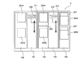
- FIG. 2A is a plan view showing the cleaning unit 4, and FIG. 2B is a side view showing the cleaning unit 4.
- the cleaning unit 4 is divided into a first cleaning chamber 190, a first transport chamber 191 and a second cleaning chamber 192, a second transport chamber 193, and a drying chamber 194. ing.
- the upper primary cleaning module 201A and the lower primary cleaning module 201B arranged along the vertical direction are arranged.
- the upper primary cleaning module 201A is located above the lower primary cleaning module 201B.
- the upper secondary cleaning module 202A and the lower secondary cleaning module 202B arranged along the vertical direction are arranged in the second cleaning chamber 192.
- the upper secondary cleaning module 202A is arranged above the lower secondary cleaning module 202B.
- the primary and secondary cleaning modules 201A, 201B, 202A, 202B are cleaning machines that clean the wafer using a cleaning liquid. Since these primary and secondary cleaning modules 201A, 201B, 202A, 202B are arranged along the vertical direction, the advantage of a small footprint area can be obtained.
- a temporary wafer placement table 203 is provided between the upper secondary cleaning module 202A and the lower secondary cleaning module 202B.
- an upper drying module 205A and a lower drying module 205B arranged along the vertical direction are arranged in the drying chamber 194.
- the upper drying module 205A and the lower drying module 205B are isolated from each other.
- Fan filter units (FFU) 207 and 207 that supply clean air into the drying modules 205A and 205B are provided above the upper drying module 205A and the lower drying module 205B, respectively.
- a first transfer robot (convey mechanism) 209 capable of moving up and down is arranged in the first transfer chamber 191, and a second transfer robot 210 capable of moving up and down is arranged in the second transfer chamber 193.
- the first transfer robot 209 and the second transfer robot 210 are movably supported by support shafts 211 and 212 extending in the vertical direction, respectively.
- the first transfer robot 209 and the second transfer robot 210 have a drive mechanism such as a motor inside, and can move up and down along the support shafts 211 and 212. Like the transfer robot 22, the first transfer robot 209 has two upper and lower hands. The first transfer robot 209 is arranged at a position where the lower hand can access the temporary storage table 180 described above (see the dotted line in FIG. 2A).
- the first transfer robot 209 holds the wafer W between the temporary stand 180, the upper primary cleaning module 201A, the lower primary cleaning module 201B, the temporary stand 203, the upper secondary cleaning module 202A, and the lower secondary cleaning module 202B. Operates to carry.
- the second transfer robot 210 operates so as to transfer the wafer W between the upper secondary cleaning module 202A, the lower secondary cleaning module 202B, the temporary stand 203, the upper drying module 205A, and the lower drying module 205B.
- the transfer robot 22 shown in FIG. 1 takes out a wafer from the upper drying module 205A or the lower drying module 205B by using the upper hand thereof, and returns the wafer to the wafer cassette.
- FIG. 3 is a diagram showing an embodiment of the damper control system 300.
- the cleaning unit 4 of the semiconductor manufacturing apparatus includes a damper control system 300 that controls the pressure in the processing module.
- the damper control system 300 may be configured to control the pressure in each cleaning module 201A, 201B, 202A, 202B as a processing module.
- the processing module in the embodiment shown in FIG. 3, each of the drying modules 205A and 205B
- the processing module includes a partition wall 216 having an opening 215 formed therein, and a shutter 217 opening and closing the opening 215.
- the partition wall 216 stores the components necessary for processing the wafer W.
- the opening 215 has a size through which the wafer W can pass.
- the transfer robot 210 makes the wafer W access the above components through the opening 215.
- the pressure in the transfer chamber 193 in which the transfer robot 210 is arranged is larger than the pressure in the partition wall 216.
- a fan filter unit (FFU) 220 that supplies clean air to the transport chamber 193 is provided above the transport chamber 193. When the fan filter unit 220 is driven, clean air flows into the transport chamber 193, and the pressure in the transport chamber 193 becomes positive.
- An exhaust duct 305 for exhausting the internal space of the partition wall 216 is connected to the partition wall 216.
- the exhaust duct 305 includes an exhaust port 305a arranged outside the housing 1.
- the exhaust duct 305 is connected to a suction source located outside the semiconductor manufacturing apparatus. Therefore, the internal space of the partition wall 216 is exhausted through the exhaust duct 305, and the pressure inside the partition wall 216 becomes a negative pressure.
- the intake pipe 306 is connected to the fan filter units 207 and 207.
- the fans 207a provided in each of the fan filter units 207 and 207 rotate, the air outside the housing 1 is sucked into the fan filter unit 207 through the intake pipe 306.
- the clean air that has passed through the fan filter unit 207 is sent to the internal space of the partition wall 216.
- the rotation speed of the fan 207a is kept constant so that the pressure inside the partition wall 216 becomes a negative pressure.
- the damper control system 300 includes an exhaust damper 310 which is connected to the exhaust duct 305 and whose opening degree can be adjusted between fully open and fully closed, a first pressure sensor 311 arranged in the internal space of the partition wall 216, and a first pressure sensor 311. 1
- the control device 315 that controls the opening degree of the exhaust damper 310 based on the pressure measured by the pressure sensor 311 is provided.
- the exhaust damper 310 is arranged outside the housing 1.
- the exhaust damper 310 has a partition plate 310a inside.
- the partition plate 310a has a size that allows the size of the flow path of the exhaust duct 305 to be adjusted, and is connected to the motor 310b that operates the partition plate 310a.
- the exhaust damper 310 is electrically connected to the control device 315.
- the exhaust damper 310 is an auto damper that can be controlled by the control device 315. Based on a command from the control device 315, the partition plate 310a is operated via the motor 310b to adjust the size of the flow path of the exhaust duct 305. To do. In this way, the control device 315 controls the opening degree of the exhaust damper 310.
- the processing module is provided with an open / close sensor 316 that detects the open / close of the shutter 217.
- the open / close sensor 316 is electrically connected to the control device 315.
- the control device 315 determines the opening / closing of the shutter 217 based on the signal sent from the opening / closing sensor 316.
- the control device 315 includes a storage device 315a that stores a program that controls the opening degree of the exhaust damper 310, and a processing device 315b that executes calculations according to the above program.
- the control device 315 may be the same as the control device 5 described above.
- the control device 315 is configured to switch the opening degree of the exhaust damper 310 to an opening degree smaller than the fully opened portion on condition that the opening and closing of the shutter 217 is switched.
- the above program includes a command to switch the opening degree of the exhaust damper 310 to an opening degree smaller than the fully opened position on condition that the opening / closing of the shutter 217 is switched. Further, in other words, in the above program, the exhaust damper 310 is made to execute an operation of switching the opening degree of the exhaust damper 310 to an opening degree smaller than the fully open position on condition that the opening / closing of the shutter 217 is switched.
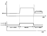
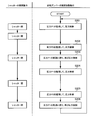
- FIG. 4 is a diagram showing an embodiment of the operation sequence of the control device 315. As shown in step S101 of FIG. 4, when the shutter 217 is closed, the control device 315 opens the exhaust damper 310 based on the pressure P1 in the partition wall 216 measured by the first pressure sensor 311. To control.
- the control device 315 calculates the difference between the predetermined set pressure and the pressure P1, and feedback-controls (more specifically, PID control) the opening degree of the exhaust damper 310 based on the difference. ..
- the control device 315 increases the displacement of the internal space of the partition wall 216 by increasing the opening degree of the exhaust damper 310. Therefore, under the condition that the amount of intake air into the internal space of the partition wall 216 is constant, the pressure inside the partition wall 216 becomes small.
- the control device 315 reduces the displacement of the internal space of the partition wall 216 by reducing the opening degree of the exhaust damper 310. Therefore, under the condition that the amount of intake air into the internal space of the partition wall 216 is constant, the pressure inside the partition wall 216 becomes large.
- the open / close sensor 316 sends a signal indicating that the shutter 217 is opened to the control device 315.
- the control device 315 switches the opening degree of the exhaust damper 310 to a predetermined opening degree.
- the predetermined opening is smaller than the fully open.
- control device 315 fixes the opening degree of the exhaust damper 310 to a predetermined opening degree on condition that the shutter 217 is opened. In this state, the transfer robot 210 transfers the wafer W to the processing module through the opening 215.
- the control device 315 When the shutter 217 is closed after the wafer W is transferred, the control device 315 returns to the monitoring of the pressure P1 and controls the opening degree of the exhaust damper 310 again based on the pressure P1 (see step S103). In this way, the control device 315 releases the feedback control of the exhaust damper 310 when the shutter 217 is opened, and starts the feedback control of the exhaust damper 310 when the shutter 217 is closed.
- FIG. 5 is a diagram showing the effect of the damper control method shown in FIG. According to the present embodiment, even if the shutter 217 is opened and the pressure in the internal space of the partition wall 216 suddenly increases, the control device 315 does not fully open the opening of the exhaust damper 310, but rather than fully opening. Keep the opening small.
- the damper control system 300 can improve the throughput of the entire process.
- the control device 315 continuously controls the opening degree of the exhaust damper 310 based on the pressure P1 (see step S104).
- the control device 315 executes the same operation as in step S102 (see step S105).
- the transfer robot 210 takes out the wafer W from the processing module through the opening 215.
- the control device 315 executes the same operation as in step S103 (see step S106).
- the damper control system 300 may include a second pressure sensor 312 and a third pressure sensor 313 arranged inside the exhaust duct 305. These pressure sensors 312 and 313 are electrically connected to the control device 315.
- the second pressure sensor 312 is arranged adjacent to the exhaust damper 310, and the third pressure sensor 313 is arranged adjacent to the partition wall 216.
- control device 315 is configured to control the opening degree of the exhaust damper 310 based on the pressure P1. In one embodiment, the control device 315 may control the opening degree of the exhaust damper 310 based on the pressure P2 measured by the second pressure sensor 312. In one embodiment, the control device 315 may control the opening degree of the exhaust damper 310 based on the pressure P3 measured by the third pressure sensor 313.
- control device 315 is configured to control the opening degree of the exhaust damper 310.
- control device 315 may be configured to control the rotational speed of the fan 207a of the fan filter unit 207 based on any of the pressures P1, P2, P3.
- the fan filter unit 207 is electrically connected to the control device 315. As the rotation speed of the fan 207a increases, the flow rate of the gas flowing into the partition wall 216 increases. Therefore, under the condition that the displacement of the internal space of the partition wall 216 is constant, the pressure inside the partition wall 216 becomes large. When the rotation speed of the fan 207a is reduced, the flow rate of the gas flowing into the partition wall 216 is reduced. Therefore, under the condition that the displacement of the internal space of the partition wall 216 is constant, the pressure inside the partition wall 216 becomes small.
- the control device 315 may control at least one of the rotation speed of the fan 207a and the opening degree of the exhaust damper 310 based on the above data.
- FIG. 6 is a diagram showing another embodiment of the operation sequence of the control device 315. As shown in step S201 of FIG. 6, when the shutter 217 is closed, the control device 315 controls the opening degree of the exhaust damper 310 based on the pressure P1 as in step S101 of FIG.
- the control device 315 continuously controls the opening degree of the exhaust damper 310 for a certain period of time based on the pressure P1.
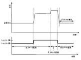
- the control device 315 switches the monitoring target of the pressure control from the first pressure sensor 311 to the second pressure sensor 312 (see FIG. 3) on condition that the shutter 217 is opened. In one embodiment, this switching operation is performed after the shutter 217 is opened and just before the shutter 217 is closed.
- the control device 315 controls the opening degree of the exhaust damper 310 based on the pressure P2 measured by the second pressure sensor 312 before the shutter 217 is closed. Therefore, even if the pressure in the partition wall 216 increases, the control device 315 can control the opening degree of the exhaust damper 310 without being affected by the pressure fluctuation in the partition wall 216.
- FIG. 7 is a diagram showing the effect of the damper control method shown in FIG.
- the second pressure sensor 312 is arranged in the exhaust duct 305 at a position closest to the suction source.
- the pressure P2 measured by the second pressure sensor 312 is not affected by the pressure fluctuation in the partition wall 216, unlike the pressure P1. Therefore, when the control device 315 switches the monitoring target of the pressure control to the second pressure sensor 312, the opening degree of the exhaust damper 310 is not fully opened, but is smaller than the fully opened degree.
- the control device 315 switches the opening degree of the exhaust damper 310 to a smaller opening degree than the fully opened portion without making the opening degree fully open. Therefore, even if the shutter 217 is closed again, the pressure inside the partition wall 216 does not drop sharply, and the undershoot phenomenon does not occur.
- the control device 315 returns to monitoring the pressure P1 and executes the same operation as in step S103 of FIG. 4 (see step S203). After that, the control device 315 executes the same operation as in step S104 of FIG. 4 (see step S204).
- the monitoring target of the pressure control is switched from the first pressure sensor 311 to the second pressure sensor 312 (see step S205).
- the control device 315 switches the monitoring target of the pressure control from the second pressure sensor 312 to the first pressure sensor 311 (see step S206).
- control device 315 may execute the same control as the control in the embodiment shown in FIG. 4 as much as possible.
- control device 315 may be configured to control the rotation speed of the fan 207a of the fan filter unit 207.
- the present invention can be used in a damper control system and a damper control method for controlling the opening degree of an exhaust damper connected to an exhaust duct.
Landscapes
- Engineering & Computer Science (AREA)
- Chemical & Material Sciences (AREA)
- Combustion & Propulsion (AREA)
- Mechanical Engineering (AREA)
- General Engineering & Computer Science (AREA)
- Container, Conveyance, Adherence, Positioning, Of Wafer (AREA)
- Ventilation (AREA)
- Mechanical Treatment Of Semiconductor (AREA)
- Cleaning Or Drying Semiconductors (AREA)
Priority Applications (2)
| Application Number | Priority Date | Filing Date | Title |
|---|---|---|---|
| SG11202112567WA SG11202112567WA (en) | 2019-05-30 | 2020-05-29 | Damper control system and damper control method |
| US17/607,999 US11967508B2 (en) | 2019-05-30 | 2020-05-29 | Damper control system and damper control method |
Applications Claiming Priority (2)
| Application Number | Priority Date | Filing Date | Title |
|---|---|---|---|
| JP2019101611A JP7143251B2 (ja) | 2019-05-30 | 2019-05-30 | ダンパー制御システムおよびダンパー制御方法 |
| JP2019-101611 | 2019-05-30 |
Publications (1)
| Publication Number | Publication Date |
|---|---|
| WO2020241848A1 true WO2020241848A1 (ja) | 2020-12-03 |
Family
ID=73552853
Family Applications (1)
| Application Number | Title | Priority Date | Filing Date |
|---|---|---|---|
| PCT/JP2020/021418 Ceased WO2020241848A1 (ja) | 2019-05-30 | 2020-05-29 | ダンパー制御システムおよびダンパー制御方法 |
Country Status (4)
| Country | Link |
|---|---|
| US (1) | US11967508B2 (https=) |
| JP (1) | JP7143251B2 (https=) |
| SG (1) | SG11202112567WA (https=) |
| WO (1) | WO2020241848A1 (https=) |
Cited By (1)
| Publication number | Priority date | Publication date | Assignee | Title |
|---|---|---|---|---|
| WO2025079474A1 (ja) * | 2023-10-11 | 2025-04-17 | 東京エレクトロン株式会社 | 基板処理装置および基板処理方法 |
Families Citing this family (1)
| Publication number | Priority date | Publication date | Assignee | Title |
|---|---|---|---|---|
| KR102737433B1 (ko) * | 2022-12-16 | 2024-12-02 | 세메스 주식회사 | 제어 유닛 및 이를 포함하는 반도체 제조 설비 |
Citations (3)
| Publication number | Priority date | Publication date | Assignee | Title |
|---|---|---|---|---|
| JP2000286219A (ja) * | 1999-03-31 | 2000-10-13 | Shibaura Mechatronics Corp | スピン処理装置およびスピン処理方法 |
| JP2006078086A (ja) * | 2004-09-09 | 2006-03-23 | Taikisha Ltd | 室圧制御システム |
| JP2009036425A (ja) * | 2007-08-01 | 2009-02-19 | Hitachi Plant Technologies Ltd | 室圧制御方法及びシステム |
Family Cites Families (18)
| Publication number | Priority date | Publication date | Assignee | Title |
|---|---|---|---|---|
| US3548865A (en) * | 1967-12-08 | 1970-12-22 | Bela P Povinger | Pressure control apparatus |
| US4375224A (en) * | 1981-01-21 | 1983-03-01 | Acutherm, Inc. | Air conditioning control equipment |
| GB8531812D0 (en) * | 1985-12-24 | 1986-02-05 | Edi Eng Ltd | Control system |
| SE458802B (sv) * | 1987-04-03 | 1989-05-08 | Stifab Ab | Regleranordning foer instaellning av ett spjaell i en ventilationskanal |
| US4796651A (en) * | 1988-03-30 | 1989-01-10 | LeRoy D. Ginn | Variable gas volume flow measuring and control methods and apparatus |
| JPH06163494A (ja) | 1992-11-20 | 1994-06-10 | Hitachi Electron Eng Co Ltd | 半導体洗浄装置の排気ガス制御機構 |
| US5363872A (en) * | 1993-03-16 | 1994-11-15 | Applied Materials, Inc. | Low particulate slit valve system and method for controlling same |
| US5518446A (en) * | 1994-07-28 | 1996-05-21 | Landis & Gyr Powers, Inc. | Fume hood exhaust terminal |
| US5758680A (en) * | 1996-03-29 | 1998-06-02 | Lam Research Corporation | Method and apparatus for pressure control in vacuum processors |
| AU1682999A (en) * | 1997-12-18 | 1999-07-05 | Nikon Corporation | Method of controlling air pressure in chamber, apparatus for the same, and exposure apparatus |
| JP4022309B2 (ja) | 1998-04-08 | 2007-12-19 | 大日本スクリーン製造株式会社 | 基板処理装置 |
| JP3623654B2 (ja) | 1998-04-24 | 2005-02-23 | 大日本スクリーン製造株式会社 | 基板処理装置 |
| US6557574B2 (en) * | 2000-04-04 | 2003-05-06 | Clifford C. Federspiel | Pressure based flow rate measurement device integrated with blades of a damper |
| DE102008010658B4 (de) * | 2008-02-22 | 2010-08-19 | Knorr-Bremse Systeme für Nutzfahrzeuge GmbH | Abgasregelsystem und Abgasregelverfahren |
| JP5744382B2 (ja) | 2008-07-24 | 2015-07-08 | 株式会社荏原製作所 | 基板処理装置および基板処理方法 |
| JP5528374B2 (ja) * | 2011-03-03 | 2014-06-25 | 東京エレクトロン株式会社 | ガス減圧供給装置、これを備えるシリンダキャビネット、バルブボックス、及び基板処理装置 |
| JP6105868B2 (ja) * | 2012-06-26 | 2017-03-29 | 株式会社不二工機 | 電動弁制御装置及び電動弁装置 |
| US9465391B2 (en) * | 2014-01-09 | 2016-10-11 | Fisher Controls International Llc | Valve positioner with overpressure protection capabilities |
-
2019
- 2019-05-30 JP JP2019101611A patent/JP7143251B2/ja active Active
-
2020
- 2020-05-29 WO PCT/JP2020/021418 patent/WO2020241848A1/ja not_active Ceased
- 2020-05-29 SG SG11202112567WA patent/SG11202112567WA/en unknown
- 2020-05-29 US US17/607,999 patent/US11967508B2/en active Active
Patent Citations (3)
| Publication number | Priority date | Publication date | Assignee | Title |
|---|---|---|---|---|
| JP2000286219A (ja) * | 1999-03-31 | 2000-10-13 | Shibaura Mechatronics Corp | スピン処理装置およびスピン処理方法 |
| JP2006078086A (ja) * | 2004-09-09 | 2006-03-23 | Taikisha Ltd | 室圧制御システム |
| JP2009036425A (ja) * | 2007-08-01 | 2009-02-19 | Hitachi Plant Technologies Ltd | 室圧制御方法及びシステム |
Cited By (1)
| Publication number | Priority date | Publication date | Assignee | Title |
|---|---|---|---|---|
| WO2025079474A1 (ja) * | 2023-10-11 | 2025-04-17 | 東京エレクトロン株式会社 | 基板処理装置および基板処理方法 |
Also Published As
| Publication number | Publication date |
|---|---|
| US20220319874A1 (en) | 2022-10-06 |
| JP2020198324A (ja) | 2020-12-10 |
| US11967508B2 (en) | 2024-04-23 |
| JP7143251B2 (ja) | 2022-09-28 |
| SG11202112567WA (en) | 2021-12-30 |
Similar Documents
| Publication | Publication Date | Title |
|---|---|---|
| JP3990567B2 (ja) | ダイヤフラムバルブ、基板処理ユニットおよび基板処理装置 | |
| US8267037B2 (en) | Substrate processing apparatus | |
| JP6190645B2 (ja) | 基板搬送方法 | |
| TWI844661B (zh) | 搬送裝置、工件處理裝置、搬送裝置的控制方法、及儲存程式的記錄媒體 | |
| US8038769B2 (en) | Liquid processing apparatus, liquid processing method and storage medium | |
| JP7153616B2 (ja) | 基板洗浄装置および基板洗浄方法 | |
| KR102343637B1 (ko) | 기판 처리 장치 및 방법 | |
| KR100797666B1 (ko) | 기판처리장치 | |
| WO2020241848A1 (ja) | ダンパー制御システムおよびダンパー制御方法 | |
| JP2015201598A (ja) | 基板処理装置 | |
| KR102315667B1 (ko) | 기판 처리 방법 및 장치 | |
| JP3771430B2 (ja) | 基板処理装置および基板処理システム | |
| JP2003100620A (ja) | 基板処理装置 | |
| JP6373796B2 (ja) | 基板研磨装置 | |
| US20070130738A1 (en) | Vacuum processing apparatus and zonal airflow generating unit | |
| WO2017094406A1 (ja) | 基板処理装置の排気装置 | |
| JP2021013987A (ja) | 基板処理システムおよび記録媒体 | |
| JP6353266B2 (ja) | 冷却装置、及び、基板処理装置 | |
| JP2016078155A (ja) | 研磨装置、及び、基板処理装置 | |
| KR102081707B1 (ko) | 밸브 유닛 및 액 공급 유닛 | |
| US12518987B2 (en) | Equipment front end module, operating method thereof, and substrate processing apparatus including same | |
| JP6091976B2 (ja) | 液体供給装置、及び基板処理装置 | |
| KR20230140864A (ko) | 액 공급 유닛 및 이를 포함하는 기판 처리 장치 | |
| JP6216258B2 (ja) | 基板処理装置 | |
| JP2015128808A (ja) | 基板処理装置の制御装置、及び基板処理装置 |
Legal Events
| Date | Code | Title | Description |
|---|---|---|---|
| 121 | Ep: the epo has been informed by wipo that ep was designated in this application |
Ref document number: 20814008 Country of ref document: EP Kind code of ref document: A1 |
|
| NENP | Non-entry into the national phase |
Ref country code: DE |
|
| 122 | Ep: pct application non-entry in european phase |
Ref document number: 20814008 Country of ref document: EP Kind code of ref document: A1 |