WO2020241848A1 - Damper control system and damper control method - Google Patents
Damper control system and damper control method Download PDFInfo
- Publication number
- WO2020241848A1 WO2020241848A1 PCT/JP2020/021418 JP2020021418W WO2020241848A1 WO 2020241848 A1 WO2020241848 A1 WO 2020241848A1 JP 2020021418 W JP2020021418 W JP 2020021418W WO 2020241848 A1 WO2020241848 A1 WO 2020241848A1
- Authority
- WO
- WIPO (PCT)
- Prior art keywords
- opening degree
- shutter
- pressure sensor
- pressure
- exhaust damper
- Prior art date
Links
Images


Classifications
-
- H—ELECTRICITY
- H01—ELECTRIC ELEMENTS
- H01L—SEMICONDUCTOR DEVICES NOT COVERED BY CLASS H10
- H01L21/00—Processes or apparatus adapted for the manufacture or treatment of semiconductor or solid state devices or of parts thereof
- H01L21/67—Apparatus specially adapted for handling semiconductor or electric solid state devices during manufacture or treatment thereof; Apparatus specially adapted for handling wafers during manufacture or treatment of semiconductor or electric solid state devices or components ; Apparatus not specifically provided for elsewhere
- H01L21/67005—Apparatus not specifically provided for elsewhere
- H01L21/67011—Apparatus for manufacture or treatment
- H01L21/67155—Apparatus for manufacturing or treating in a plurality of work-stations
- H01L21/67207—Apparatus for manufacturing or treating in a plurality of work-stations comprising a chamber adapted to a particular process
- H01L21/67219—Apparatus for manufacturing or treating in a plurality of work-stations comprising a chamber adapted to a particular process comprising at least one polishing chamber
-
- F—MECHANICAL ENGINEERING; LIGHTING; HEATING; WEAPONS; BLASTING
- F24—HEATING; RANGES; VENTILATING
- F24F—AIR-CONDITIONING; AIR-HUMIDIFICATION; VENTILATION; USE OF AIR CURRENTS FOR SCREENING
- F24F7/00—Ventilation
- F24F7/007—Ventilation with forced flow
-
- H—ELECTRICITY
- H01—ELECTRIC ELEMENTS
- H01L—SEMICONDUCTOR DEVICES NOT COVERED BY CLASS H10
- H01L21/00—Processes or apparatus adapted for the manufacture or treatment of semiconductor or solid state devices or of parts thereof
- H01L21/02—Manufacture or treatment of semiconductor devices or of parts thereof
- H01L21/04—Manufacture or treatment of semiconductor devices or of parts thereof the devices having at least one potential-jump barrier or surface barrier, e.g. PN junction, depletion layer or carrier concentration layer
- H01L21/18—Manufacture or treatment of semiconductor devices or of parts thereof the devices having at least one potential-jump barrier or surface barrier, e.g. PN junction, depletion layer or carrier concentration layer the devices having semiconductor bodies comprising elements of Group IV of the Periodic System or AIIIBV compounds with or without impurities, e.g. doping materials
- H01L21/30—Treatment of semiconductor bodies using processes or apparatus not provided for in groups H01L21/20 - H01L21/26
- H01L21/302—Treatment of semiconductor bodies using processes or apparatus not provided for in groups H01L21/20 - H01L21/26 to change their surface-physical characteristics or shape, e.g. etching, polishing, cutting
- H01L21/304—Mechanical treatment, e.g. grinding, polishing, cutting
-
- H—ELECTRICITY
- H01—ELECTRIC ELEMENTS
- H01L—SEMICONDUCTOR DEVICES NOT COVERED BY CLASS H10
- H01L21/00—Processes or apparatus adapted for the manufacture or treatment of semiconductor or solid state devices or of parts thereof
- H01L21/67—Apparatus specially adapted for handling semiconductor or electric solid state devices during manufacture or treatment thereof; Apparatus specially adapted for handling wafers during manufacture or treatment of semiconductor or electric solid state devices or components ; Apparatus not specifically provided for elsewhere
- H01L21/67005—Apparatus not specifically provided for elsewhere
- H01L21/67011—Apparatus for manufacture or treatment
- H01L21/67017—Apparatus for fluid treatment
- H01L21/67028—Apparatus for fluid treatment for cleaning followed by drying, rinsing, stripping, blasting or the like
- H01L21/67034—Apparatus for fluid treatment for cleaning followed by drying, rinsing, stripping, blasting or the like for drying
-
- H—ELECTRICITY
- H01—ELECTRIC ELEMENTS
- H01L—SEMICONDUCTOR DEVICES NOT COVERED BY CLASS H10
- H01L21/00—Processes or apparatus adapted for the manufacture or treatment of semiconductor or solid state devices or of parts thereof
- H01L21/67—Apparatus specially adapted for handling semiconductor or electric solid state devices during manufacture or treatment thereof; Apparatus specially adapted for handling wafers during manufacture or treatment of semiconductor or electric solid state devices or components ; Apparatus not specifically provided for elsewhere
- H01L21/67005—Apparatus not specifically provided for elsewhere
- H01L21/67011—Apparatus for manufacture or treatment
- H01L21/67017—Apparatus for fluid treatment
- H01L21/67028—Apparatus for fluid treatment for cleaning followed by drying, rinsing, stripping, blasting or the like
- H01L21/6704—Apparatus for fluid treatment for cleaning followed by drying, rinsing, stripping, blasting or the like for wet cleaning or washing
-
- H—ELECTRICITY
- H01—ELECTRIC ELEMENTS
- H01L—SEMICONDUCTOR DEVICES NOT COVERED BY CLASS H10
- H01L21/00—Processes or apparatus adapted for the manufacture or treatment of semiconductor or solid state devices or of parts thereof
- H01L21/67—Apparatus specially adapted for handling semiconductor or electric solid state devices during manufacture or treatment thereof; Apparatus specially adapted for handling wafers during manufacture or treatment of semiconductor or electric solid state devices or components ; Apparatus not specifically provided for elsewhere
- H01L21/67005—Apparatus not specifically provided for elsewhere
- H01L21/67011—Apparatus for manufacture or treatment
- H01L21/67126—Apparatus for sealing, encapsulating, glassing, decapsulating or the like
-
- H—ELECTRICITY
- H01—ELECTRIC ELEMENTS
- H01L—SEMICONDUCTOR DEVICES NOT COVERED BY CLASS H10
- H01L21/00—Processes or apparatus adapted for the manufacture or treatment of semiconductor or solid state devices or of parts thereof
- H01L21/67—Apparatus specially adapted for handling semiconductor or electric solid state devices during manufacture or treatment thereof; Apparatus specially adapted for handling wafers during manufacture or treatment of semiconductor or electric solid state devices or components ; Apparatus not specifically provided for elsewhere
- H01L21/67005—Apparatus not specifically provided for elsewhere
- H01L21/67011—Apparatus for manufacture or treatment
- H01L21/67155—Apparatus for manufacturing or treating in a plurality of work-stations
- H01L21/67161—Apparatus for manufacturing or treating in a plurality of work-stations characterized by the layout of the process chambers
- H01L21/67178—Apparatus for manufacturing or treating in a plurality of work-stations characterized by the layout of the process chambers vertical arrangement
-
- H—ELECTRICITY
- H01—ELECTRIC ELEMENTS
- H01L—SEMICONDUCTOR DEVICES NOT COVERED BY CLASS H10
- H01L21/00—Processes or apparatus adapted for the manufacture or treatment of semiconductor or solid state devices or of parts thereof
- H01L21/67—Apparatus specially adapted for handling semiconductor or electric solid state devices during manufacture or treatment thereof; Apparatus specially adapted for handling wafers during manufacture or treatment of semiconductor or electric solid state devices or components ; Apparatus not specifically provided for elsewhere
- H01L21/67005—Apparatus not specifically provided for elsewhere
- H01L21/67011—Apparatus for manufacture or treatment
- H01L21/67155—Apparatus for manufacturing or treating in a plurality of work-stations
- H01L21/6719—Apparatus for manufacturing or treating in a plurality of work-stations characterized by the construction of the processing chambers, e.g. modular processing chambers
-
- H—ELECTRICITY
- H01—ELECTRIC ELEMENTS
- H01L—SEMICONDUCTOR DEVICES NOT COVERED BY CLASS H10
- H01L21/00—Processes or apparatus adapted for the manufacture or treatment of semiconductor or solid state devices or of parts thereof
- H01L21/67—Apparatus specially adapted for handling semiconductor or electric solid state devices during manufacture or treatment thereof; Apparatus specially adapted for handling wafers during manufacture or treatment of semiconductor or electric solid state devices or components ; Apparatus not specifically provided for elsewhere
- H01L21/67005—Apparatus not specifically provided for elsewhere
- H01L21/67242—Apparatus for monitoring, sorting or marking
- H01L21/67253—Process monitoring, e.g. flow or thickness monitoring
-
- H—ELECTRICITY
- H01—ELECTRIC ELEMENTS
- H01L—SEMICONDUCTOR DEVICES NOT COVERED BY CLASS H10
- H01L21/00—Processes or apparatus adapted for the manufacture or treatment of semiconductor or solid state devices or of parts thereof
- H01L21/67—Apparatus specially adapted for handling semiconductor or electric solid state devices during manufacture or treatment thereof; Apparatus specially adapted for handling wafers during manufacture or treatment of semiconductor or electric solid state devices or components ; Apparatus not specifically provided for elsewhere
- H01L21/677—Apparatus specially adapted for handling semiconductor or electric solid state devices during manufacture or treatment thereof; Apparatus specially adapted for handling wafers during manufacture or treatment of semiconductor or electric solid state devices or components ; Apparatus not specifically provided for elsewhere for conveying, e.g. between different workstations
- H01L21/67739—Apparatus specially adapted for handling semiconductor or electric solid state devices during manufacture or treatment thereof; Apparatus specially adapted for handling wafers during manufacture or treatment of semiconductor or electric solid state devices or components ; Apparatus not specifically provided for elsewhere for conveying, e.g. between different workstations into and out of processing chamber
- H01L21/67748—Apparatus specially adapted for handling semiconductor or electric solid state devices during manufacture or treatment thereof; Apparatus specially adapted for handling wafers during manufacture or treatment of semiconductor or electric solid state devices or components ; Apparatus not specifically provided for elsewhere for conveying, e.g. between different workstations into and out of processing chamber horizontal transfer of a single workpiece
-
- H—ELECTRICITY
- H01—ELECTRIC ELEMENTS
- H01L—SEMICONDUCTOR DEVICES NOT COVERED BY CLASS H10
- H01L21/00—Processes or apparatus adapted for the manufacture or treatment of semiconductor or solid state devices or of parts thereof
- H01L21/67—Apparatus specially adapted for handling semiconductor or electric solid state devices during manufacture or treatment thereof; Apparatus specially adapted for handling wafers during manufacture or treatment of semiconductor or electric solid state devices or components ; Apparatus not specifically provided for elsewhere
- H01L21/677—Apparatus specially adapted for handling semiconductor or electric solid state devices during manufacture or treatment thereof; Apparatus specially adapted for handling wafers during manufacture or treatment of semiconductor or electric solid state devices or components ; Apparatus not specifically provided for elsewhere for conveying, e.g. between different workstations
- H01L21/67739—Apparatus specially adapted for handling semiconductor or electric solid state devices during manufacture or treatment thereof; Apparatus specially adapted for handling wafers during manufacture or treatment of semiconductor or electric solid state devices or components ; Apparatus not specifically provided for elsewhere for conveying, e.g. between different workstations into and out of processing chamber
- H01L21/67742—Mechanical parts of transfer devices
Definitions
- the present invention relates to a damper control system and a damper control method for controlling the opening degree of an exhaust damper connected to an exhaust duct.
- a structure having a partition wall provided between a space maintained by positive pressure (positive pressure chamber) and a space maintained by negative pressure (negative pressure chamber) is known.
- positive pressure positive pressure chamber
- negative pressure negative pressure chamber
- Japanese Unexamined Patent Publication No. 2010-50436 Japanese Unexamined Patent Publication No. 11-307499 Japanese Unexamined Patent Publication No. 11-290793 Japanese Unexamined Patent Publication No. 2000-286219 Japanese Unexamined Patent Publication No. 6-163494
- FIG. 8 is a diagram for explaining a problem associated with pressure fluctuation in the negative pressure chamber. As shown in FIG. 8, when the shutter is opened, the gas in the positive pressure chamber flows into the negative pressure chamber. Then, the pressure in the negative pressure chamber increases. In order to exhaust the negative pressure chamber, the opening degree of the exhaust damper connected to the exhaust duct is fully opened.
- the object to be transported may be processed in a negative pressure chamber maintained at a predetermined pressure.
- the process of the object to be transported cannot be executed until the pressure in the negative pressure chamber reaches a predetermined pressure. As a result, the throughput of the entire process is reduced.
- an object of the present invention is to provide a damper control system and a damper control method capable of preventing the occurrence of the undershoot phenomenon.
- an exhaust damper connected to an exhaust duct attached to the partition wall of the processing module and whose opening degree can be adjusted between fully open and fully closed, and a first pressure sensor arranged in the internal space of the partition wall.
- a control device that controls the opening degree of the exhaust damper based on the pressure measured by the first pressure sensor, and the control device opens a shutter that opens and closes an opening formed in the partition wall.
- a system that switches the opening degree of the exhaust damper to an opening degree smaller than the fully opened state on condition that the pressure is increased.
- the control device controls the opening degree of the exhaust damper based on the pressure measured by the first pressure sensor, provided that the shutter is closed, and the shutter is opened. On condition that the exhaust damper is opened, the opening degree of the exhaust damper is fixed to a predetermined opening degree.
- the damper control system further comprises a second pressure sensor located in the exhaust duct, the control device being provided by the first pressure sensor, provided that the shutter is closed. The opening degree of the exhaust damper is controlled based on the measured pressure, and the monitoring target is switched from the first pressure sensor to the second pressure sensor on condition that the shutter is opened.
- the control device controls the opening degree of the exhaust damper based on the pressure measured by the second pressure sensor after the shutter is opened and immediately before it is closed.
- it is a method of controlling an exhaust damper connected to an exhaust duct attached to a partition wall of a processing module, based on the pressure measured by a first pressure sensor arranged in the internal space of the partition wall.
- the opening degree of the exhaust damper is controlled based on the pressure measured by the first pressure sensor, provided that the shutter is closed, and the shutter is opened. As a result, the opening degree of the exhaust damper is fixed to a predetermined opening degree. In one aspect, the opening degree of the exhaust damper is controlled based on the pressure measured by the first pressure sensor, provided that the shutter is closed, and the shutter is opened. As a result, the monitoring target is switched from the first pressure sensor to the second pressure sensor arranged in the exhaust duct. In one aspect, the opening degree of the exhaust damper is controlled based on the pressure measured by the second pressure sensor after the shutter is opened and immediately before it is closed.
- the processing module can execute the processing of the conveyed object immediately after the conveyed object (for example, the wafer) is conveyed to the processing module.
- the damper control system can improve the throughput of the entire process.
- FIG. 2A is a plan view showing the cleaning unit.
- FIG. 2B is a side view showing the cleaning unit.
- FIG. 1 is a plan view showing an embodiment of a semiconductor manufacturing apparatus.
- the semiconductor manufacturing apparatus includes a substantially rectangular housing 1, and the inside of the housing 1 is divided into a load / unload unit 2, a polishing unit 3, and a cleaning unit 4 by partition walls 1a and 1b. Has been done.
- the load / unload unit 2, the polishing unit 3, and the cleaning unit 4 are assembled independently and exhausted independently.
- the semiconductor manufacturing apparatus includes a control device 5 that controls a substrate processing operation.
- the load / unload unit 2 includes two or more (four in this embodiment) front load units 20 on which wafer cassettes for stocking a large number of wafers (boards) are placed. These front load portions 20 are arranged adjacent to the housing 1 and are arranged along the width direction (direction perpendicular to the longitudinal direction) of the semiconductor manufacturing apparatus. An open cassette, a SMIF (Standard Manufacturing Interface) pod, or a FOUP (Front Opening Unified Pod) can be mounted on the front load unit 20.
- SMIF Standard Manufacturing Interface
- FOUP Front Opening Unified Pod
- a traveling mechanism 21 is laid along the line of the front load portion 20, and two transfer robots that can move along the arrangement direction of the wafer cassettes on the traveling mechanism 21. (Loader, transport mechanism) 22 is installed.
- the transfer robot 22 can access the wafer cassette mounted on the front load unit 20 by moving on the traveling mechanism 21.
- the polishing unit 3 is an area where the wafer is polished (flattened), and includes a first polishing unit 3A, a second polishing unit 3B, a third polishing unit 3C, and a fourth polishing unit 3D. As shown in FIG. 1, these first polishing unit 3A, second polishing unit 3B, third polishing unit 3C, and fourth polishing unit 3D are arranged along the longitudinal direction of the semiconductor manufacturing apparatus.
- the first polishing unit 3A polishes while holding a polishing table 30A to which a polishing pad 10 having a polishing surface is attached and pressing the wafer against the polishing pad 10 on the polishing table 30A.
- the atomizer 34A comprises atomizing a mixed fluid of a liquid (for example, pure water) and a gas (for example, nitrogen gas) or a liquid (for example, pure water) and injecting the liquid (for example, pure water) onto the polished surface.
- the second polishing unit 3B includes a polishing table 30B, a top ring 31B, a polishing liquid supply nozzle 32B, a dresser 33B, and an atomizer 34B.
- the third polishing unit 3C includes a polishing table 30C, a top ring 31C, a polishing liquid supply nozzle 32C, a dresser 33C, and an atomizer 34C.
- the fourth polishing unit 3D includes a polishing table 30D, a top ring 31D, a polishing liquid supply nozzle 32D, a dresser 33D, and an atomizer 34D.
- the first linear transporter 6 is arranged adjacent to the first polishing unit 3A and the second polishing unit 3B.
- the first linear transporter 6 has four transport positions (first transport position TP1, second transport position TP2, and third transport in order from the load / unload unit side) along the direction in which the polishing units 3A and 3B are arranged. It is a mechanism for transferring the wafer between the position TP3 and the fourth transfer position TP4).
- the second linear transporter 7 is arranged adjacent to the third polishing unit 3C and the fourth polishing unit 3D.
- the second linear transporter 7 has three transport positions along the direction in which the polishing units 3C and 3D are arranged (the fifth transport position TP5, the sixth transport position TP6, and the seventh transport in order from the load / unload unit side). It is a mechanism for transporting wafers between positions (position TP7).
- the wafer is conveyed to the polishing units 3A and 3B by the first linear transporter 6.
- the top ring 31A of the first polishing unit 3A moves between the polishing position and the second transport position TP2 by the swing operation of the top ring head. Therefore, the transfer of the wafer to the top ring 31A is performed at the second transfer position TP2.
- the top ring 31B of the second polishing unit 3B moves between the polishing position and the third transfer position TP3, and the wafer is delivered to the top ring 31B at the third transfer position TP3.
- the top ring 31C of the third polishing unit 3C moves between the polishing position and the sixth transfer position TP6, and the wafer is delivered to the top ring 31C at the sixth transfer position TP6.
- the top ring 31D of the 4th polishing unit 3D moves between the polishing position and the 7th transfer position TP7, and the wafer is transferred to the top ring 31D at the 7th transfer position TP7.
- a lifter 11 for receiving the wafer from the transfer robot 22 is arranged.
- the wafer is passed from the transfer robot 22 to the first linear transporter 6 via the lifter 11.
- a shutter (not shown) is provided on the partition wall 1a so as to be located between the lifter 11 and the transfer robot 22 so that the shutter is opened when the wafer is transferred and the wafer is transferred from the transfer robot 22 to the lifter 11. It has become.
- a swing transporter 12 is arranged between the first linear transporter 6, the second linear transporter 7, and the cleaning unit 4.
- the swing transporter 12 has a hand that can move between the fourth transport position TP4 and the fifth transport position TP5, and transfers the wafer from the first linear transporter 6 to the second linear transporter 7. Is performed by the swing transporter 12.
- the wafer is conveyed to the third polishing unit 3C and / or the fourth polishing unit 3D by the second linear transporter 7. Further, the wafer polished by the polishing unit 3 is conveyed to the cleaning unit 4 via the swing transporter 12.
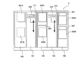
- FIG. 2A is a plan view showing the cleaning unit 4, and FIG. 2B is a side view showing the cleaning unit 4.
- the cleaning unit 4 is divided into a first cleaning chamber 190, a first transport chamber 191 and a second cleaning chamber 192, a second transport chamber 193, and a drying chamber 194. ing.
- the upper primary cleaning module 201A and the lower primary cleaning module 201B arranged along the vertical direction are arranged.
- the upper primary cleaning module 201A is located above the lower primary cleaning module 201B.
- the upper secondary cleaning module 202A and the lower secondary cleaning module 202B arranged along the vertical direction are arranged in the second cleaning chamber 192.
- the upper secondary cleaning module 202A is arranged above the lower secondary cleaning module 202B.
- the primary and secondary cleaning modules 201A, 201B, 202A, 202B are cleaning machines that clean the wafer using a cleaning liquid. Since these primary and secondary cleaning modules 201A, 201B, 202A, 202B are arranged along the vertical direction, the advantage of a small footprint area can be obtained.
- a temporary wafer placement table 203 is provided between the upper secondary cleaning module 202A and the lower secondary cleaning module 202B.
- an upper drying module 205A and a lower drying module 205B arranged along the vertical direction are arranged in the drying chamber 194.
- the upper drying module 205A and the lower drying module 205B are isolated from each other.
- Fan filter units (FFU) 207 and 207 that supply clean air into the drying modules 205A and 205B are provided above the upper drying module 205A and the lower drying module 205B, respectively.
- a first transfer robot (convey mechanism) 209 capable of moving up and down is arranged in the first transfer chamber 191, and a second transfer robot 210 capable of moving up and down is arranged in the second transfer chamber 193.
- the first transfer robot 209 and the second transfer robot 210 are movably supported by support shafts 211 and 212 extending in the vertical direction, respectively.
- the first transfer robot 209 and the second transfer robot 210 have a drive mechanism such as a motor inside, and can move up and down along the support shafts 211 and 212. Like the transfer robot 22, the first transfer robot 209 has two upper and lower hands. The first transfer robot 209 is arranged at a position where the lower hand can access the temporary storage table 180 described above (see the dotted line in FIG. 2A).
- the first transfer robot 209 holds the wafer W between the temporary stand 180, the upper primary cleaning module 201A, the lower primary cleaning module 201B, the temporary stand 203, the upper secondary cleaning module 202A, and the lower secondary cleaning module 202B. Operates to carry.
- the second transfer robot 210 operates so as to transfer the wafer W between the upper secondary cleaning module 202A, the lower secondary cleaning module 202B, the temporary stand 203, the upper drying module 205A, and the lower drying module 205B.
- the transfer robot 22 shown in FIG. 1 takes out a wafer from the upper drying module 205A or the lower drying module 205B by using the upper hand thereof, and returns the wafer to the wafer cassette.
- FIG. 3 is a diagram showing an embodiment of the damper control system 300.
- the cleaning unit 4 of the semiconductor manufacturing apparatus includes a damper control system 300 that controls the pressure in the processing module.
- the damper control system 300 may be configured to control the pressure in each cleaning module 201A, 201B, 202A, 202B as a processing module.
- the processing module in the embodiment shown in FIG. 3, each of the drying modules 205A and 205B
- the processing module includes a partition wall 216 having an opening 215 formed therein, and a shutter 217 opening and closing the opening 215.
- the partition wall 216 stores the components necessary for processing the wafer W.
- the opening 215 has a size through which the wafer W can pass.
- the transfer robot 210 makes the wafer W access the above components through the opening 215.
- the pressure in the transfer chamber 193 in which the transfer robot 210 is arranged is larger than the pressure in the partition wall 216.
- a fan filter unit (FFU) 220 that supplies clean air to the transport chamber 193 is provided above the transport chamber 193. When the fan filter unit 220 is driven, clean air flows into the transport chamber 193, and the pressure in the transport chamber 193 becomes positive.
- An exhaust duct 305 for exhausting the internal space of the partition wall 216 is connected to the partition wall 216.
- the exhaust duct 305 includes an exhaust port 305a arranged outside the housing 1.
- the exhaust duct 305 is connected to a suction source located outside the semiconductor manufacturing apparatus. Therefore, the internal space of the partition wall 216 is exhausted through the exhaust duct 305, and the pressure inside the partition wall 216 becomes a negative pressure.
- the intake pipe 306 is connected to the fan filter units 207 and 207.
- the fans 207a provided in each of the fan filter units 207 and 207 rotate, the air outside the housing 1 is sucked into the fan filter unit 207 through the intake pipe 306.
- the clean air that has passed through the fan filter unit 207 is sent to the internal space of the partition wall 216.
- the rotation speed of the fan 207a is kept constant so that the pressure inside the partition wall 216 becomes a negative pressure.
- the damper control system 300 includes an exhaust damper 310 which is connected to the exhaust duct 305 and whose opening degree can be adjusted between fully open and fully closed, a first pressure sensor 311 arranged in the internal space of the partition wall 216, and a first pressure sensor 311. 1
- the control device 315 that controls the opening degree of the exhaust damper 310 based on the pressure measured by the pressure sensor 311 is provided.
- the exhaust damper 310 is arranged outside the housing 1.
- the exhaust damper 310 has a partition plate 310a inside.
- the partition plate 310a has a size that allows the size of the flow path of the exhaust duct 305 to be adjusted, and is connected to the motor 310b that operates the partition plate 310a.
- the exhaust damper 310 is electrically connected to the control device 315.
- the exhaust damper 310 is an auto damper that can be controlled by the control device 315. Based on a command from the control device 315, the partition plate 310a is operated via the motor 310b to adjust the size of the flow path of the exhaust duct 305. To do. In this way, the control device 315 controls the opening degree of the exhaust damper 310.
- the processing module is provided with an open / close sensor 316 that detects the open / close of the shutter 217.
- the open / close sensor 316 is electrically connected to the control device 315.
- the control device 315 determines the opening / closing of the shutter 217 based on the signal sent from the opening / closing sensor 316.
- the control device 315 includes a storage device 315a that stores a program that controls the opening degree of the exhaust damper 310, and a processing device 315b that executes calculations according to the above program.
- the control device 315 may be the same as the control device 5 described above.
- the control device 315 is configured to switch the opening degree of the exhaust damper 310 to an opening degree smaller than the fully opened portion on condition that the opening and closing of the shutter 217 is switched.
- the above program includes a command to switch the opening degree of the exhaust damper 310 to an opening degree smaller than the fully opened position on condition that the opening / closing of the shutter 217 is switched. Further, in other words, in the above program, the exhaust damper 310 is made to execute an operation of switching the opening degree of the exhaust damper 310 to an opening degree smaller than the fully open position on condition that the opening / closing of the shutter 217 is switched.
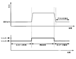
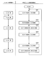
- FIG. 4 is a diagram showing an embodiment of the operation sequence of the control device 315. As shown in step S101 of FIG. 4, when the shutter 217 is closed, the control device 315 opens the exhaust damper 310 based on the pressure P1 in the partition wall 216 measured by the first pressure sensor 311. To control.
- the control device 315 calculates the difference between the predetermined set pressure and the pressure P1, and feedback-controls (more specifically, PID control) the opening degree of the exhaust damper 310 based on the difference. ..
- the control device 315 increases the displacement of the internal space of the partition wall 216 by increasing the opening degree of the exhaust damper 310. Therefore, under the condition that the amount of intake air into the internal space of the partition wall 216 is constant, the pressure inside the partition wall 216 becomes small.
- the control device 315 reduces the displacement of the internal space of the partition wall 216 by reducing the opening degree of the exhaust damper 310. Therefore, under the condition that the amount of intake air into the internal space of the partition wall 216 is constant, the pressure inside the partition wall 216 becomes large.
- the open / close sensor 316 sends a signal indicating that the shutter 217 is opened to the control device 315.
- the control device 315 switches the opening degree of the exhaust damper 310 to a predetermined opening degree.
- the predetermined opening is smaller than the fully open.
- control device 315 fixes the opening degree of the exhaust damper 310 to a predetermined opening degree on condition that the shutter 217 is opened. In this state, the transfer robot 210 transfers the wafer W to the processing module through the opening 215.
- the control device 315 When the shutter 217 is closed after the wafer W is transferred, the control device 315 returns to the monitoring of the pressure P1 and controls the opening degree of the exhaust damper 310 again based on the pressure P1 (see step S103). In this way, the control device 315 releases the feedback control of the exhaust damper 310 when the shutter 217 is opened, and starts the feedback control of the exhaust damper 310 when the shutter 217 is closed.
- FIG. 5 is a diagram showing the effect of the damper control method shown in FIG. According to the present embodiment, even if the shutter 217 is opened and the pressure in the internal space of the partition wall 216 suddenly increases, the control device 315 does not fully open the opening of the exhaust damper 310, but rather than fully opening. Keep the opening small.
- the damper control system 300 can improve the throughput of the entire process.
- the control device 315 continuously controls the opening degree of the exhaust damper 310 based on the pressure P1 (see step S104).
- the control device 315 executes the same operation as in step S102 (see step S105).
- the transfer robot 210 takes out the wafer W from the processing module through the opening 215.
- the control device 315 executes the same operation as in step S103 (see step S106).
- the damper control system 300 may include a second pressure sensor 312 and a third pressure sensor 313 arranged inside the exhaust duct 305. These pressure sensors 312 and 313 are electrically connected to the control device 315.
- the second pressure sensor 312 is arranged adjacent to the exhaust damper 310, and the third pressure sensor 313 is arranged adjacent to the partition wall 216.
- control device 315 is configured to control the opening degree of the exhaust damper 310 based on the pressure P1. In one embodiment, the control device 315 may control the opening degree of the exhaust damper 310 based on the pressure P2 measured by the second pressure sensor 312. In one embodiment, the control device 315 may control the opening degree of the exhaust damper 310 based on the pressure P3 measured by the third pressure sensor 313.
- control device 315 is configured to control the opening degree of the exhaust damper 310.
- control device 315 may be configured to control the rotational speed of the fan 207a of the fan filter unit 207 based on any of the pressures P1, P2, P3.
- the fan filter unit 207 is electrically connected to the control device 315. As the rotation speed of the fan 207a increases, the flow rate of the gas flowing into the partition wall 216 increases. Therefore, under the condition that the displacement of the internal space of the partition wall 216 is constant, the pressure inside the partition wall 216 becomes large. When the rotation speed of the fan 207a is reduced, the flow rate of the gas flowing into the partition wall 216 is reduced. Therefore, under the condition that the displacement of the internal space of the partition wall 216 is constant, the pressure inside the partition wall 216 becomes small.
- the control device 315 may control at least one of the rotation speed of the fan 207a and the opening degree of the exhaust damper 310 based on the above data.
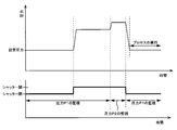
- FIG. 6 is a diagram showing another embodiment of the operation sequence of the control device 315. As shown in step S201 of FIG. 6, when the shutter 217 is closed, the control device 315 controls the opening degree of the exhaust damper 310 based on the pressure P1 as in step S101 of FIG.
- the control device 315 continuously controls the opening degree of the exhaust damper 310 for a certain period of time based on the pressure P1.
- the control device 315 switches the monitoring target of the pressure control from the first pressure sensor 311 to the second pressure sensor 312 (see FIG. 3) on condition that the shutter 217 is opened. In one embodiment, this switching operation is performed after the shutter 217 is opened and just before the shutter 217 is closed.
- the control device 315 controls the opening degree of the exhaust damper 310 based on the pressure P2 measured by the second pressure sensor 312 before the shutter 217 is closed. Therefore, even if the pressure in the partition wall 216 increases, the control device 315 can control the opening degree of the exhaust damper 310 without being affected by the pressure fluctuation in the partition wall 216.
- FIG. 7 is a diagram showing the effect of the damper control method shown in FIG.
- the second pressure sensor 312 is arranged in the exhaust duct 305 at a position closest to the suction source.
- the pressure P2 measured by the second pressure sensor 312 is not affected by the pressure fluctuation in the partition wall 216, unlike the pressure P1. Therefore, when the control device 315 switches the monitoring target of the pressure control to the second pressure sensor 312, the opening degree of the exhaust damper 310 is not fully opened, but is smaller than the fully opened degree.
- the control device 315 switches the opening degree of the exhaust damper 310 to a smaller opening degree than the fully opened portion without making the opening degree fully open. Therefore, even if the shutter 217 is closed again, the pressure inside the partition wall 216 does not drop sharply, and the undershoot phenomenon does not occur.
- the control device 315 returns to monitoring the pressure P1 and executes the same operation as in step S103 of FIG. 4 (see step S203). After that, the control device 315 executes the same operation as in step S104 of FIG. 4 (see step S204).
- the monitoring target of the pressure control is switched from the first pressure sensor 311 to the second pressure sensor 312 (see step S205).
- the control device 315 switches the monitoring target of the pressure control from the second pressure sensor 312 to the first pressure sensor 311 (see step S206).
- control device 315 may execute the same control as the control in the embodiment shown in FIG. 4 as much as possible.
- control device 315 may be configured to control the rotation speed of the fan 207a of the fan filter unit 207.
- the present invention can be used in a damper control system and a damper control method for controlling the opening degree of an exhaust damper connected to an exhaust duct.
Abstract
The present invention relates to a damper control system and damper control method for controlling the opening degree of an exhaust damper connected to an exhaust duct. This damper control system (300) includes an exhaust damper (310), a first pressure sensor (311), and a control device (315) that controls the opening degree of the exhaust damper (310). The control device (315) switches the opening degree of the exhaust damper (310) to an opening degree smaller than a full-open position, on condition that the shutter (217) is open.
Description
本発明は、排気ダクトに接続された排気ダンパーの開度を制御するダンパー制御システムおよびダンパー制御方法に関する。
The present invention relates to a damper control system and a damper control method for controlling the opening degree of an exhaust damper connected to an exhaust duct.
陽圧に維持された空間(陽圧室)と陰圧に維持された空間(陰圧室)との間に設けられた隔壁を備える構造物が知られている。隔壁に設けられたシャッターが開かれると、搬送対象物は陽圧室から陰圧室に搬送される。
A structure having a partition wall provided between a space maintained by positive pressure (positive pressure chamber) and a space maintained by negative pressure (negative pressure chamber) is known. When the shutter provided on the partition wall is opened, the object to be transported is transported from the positive pressure chamber to the negative pressure chamber.
図8は、陰圧室の圧力変動に伴う問題を説明するための図である。図8に示すように、シャッターが開かれると、陽圧室の気体が陰圧室に流れ込む。すると、陰圧室の圧力が大きくなる。陰圧室を排気するために、排気ダクトに接続された排気ダンパーの開度は全開となる。
FIG. 8 is a diagram for explaining a problem associated with pressure fluctuation in the negative pressure chamber. As shown in FIG. 8, when the shutter is opened, the gas in the positive pressure chamber flows into the negative pressure chamber. Then, the pressure in the negative pressure chamber increases. In order to exhaust the negative pressure chamber, the opening degree of the exhaust damper connected to the exhaust duct is fully opened.
その後、シャッターが閉じられると、陽圧室からの気体の流入が遮断される。しかしながら、シャッターが閉じられた直後では、排気ダンパーの開度は全開であるため、陰圧室の圧力は急激に下がってしまう。結果として、アンダーシュート現象と呼ばれる圧力変動が発生してしまい、陰圧室の圧力が所定の圧力に戻るまでに、多くの時間がかかってしまう。
After that, when the shutter is closed, the inflow of gas from the positive pressure chamber is blocked. However, immediately after the shutter is closed, the opening degree of the exhaust damper is fully opened, so that the pressure in the negative pressure chamber drops sharply. As a result, a pressure fluctuation called an undershoot phenomenon occurs, and it takes a lot of time for the pressure in the negative pressure chamber to return to a predetermined pressure.
搬送対象物は、所定の圧力に維持された陰圧室でプロセスされる場合がある。アンダーシュート現象が発生すると、陰圧室の圧力が所定の圧力に到達するまでの間、搬送対象物のプロセスを実行することができない。結果として、プロセス全体のスループットが低下してしまう。
The object to be transported may be processed in a negative pressure chamber maintained at a predetermined pressure. When the undershoot phenomenon occurs, the process of the object to be transported cannot be executed until the pressure in the negative pressure chamber reaches a predetermined pressure. As a result, the throughput of the entire process is reduced.
そこで、本発明は、アンダーシュート現象の発生を防止することができるダンパー制御システムおよびダンパー制御方法を提供することを目的とする。
Therefore, an object of the present invention is to provide a damper control system and a damper control method capable of preventing the occurrence of the undershoot phenomenon.
一態様では、処理モジュールの隔壁に取り付けられた排気ダクトに接続され、かつ全開と全閉との間で開度を調整可能な排気ダンパーと、前記隔壁の内部空間に配置された第1圧力センサと、前記第1圧力センサによって測定された圧力に基づいて、前記排気ダンパーの開度を制御する制御装置と、を備え、前記制御装置は、前記隔壁に形成された開口を開閉するシャッターが開かれていることを条件として、前記排気ダンパーの開度を全開よりも小さな開度に切り替える、システムが提供される。
In one aspect, an exhaust damper connected to an exhaust duct attached to the partition wall of the processing module and whose opening degree can be adjusted between fully open and fully closed, and a first pressure sensor arranged in the internal space of the partition wall. A control device that controls the opening degree of the exhaust damper based on the pressure measured by the first pressure sensor, and the control device opens a shutter that opens and closes an opening formed in the partition wall. Provided is a system that switches the opening degree of the exhaust damper to an opening degree smaller than the fully opened state on condition that the pressure is increased.
一態様では、前記制御装置は、前記シャッターが閉じられていることを条件として、前記第1圧力センサによって測定された圧力に基づいて、前記排気ダンパーの開度を制御し、前記シャッターが開かれていることを条件として、前記排気ダンパーの開度を所定の開度に固定する。
一態様では、前記ダンパー制御システムは、前記排気ダクトに配置された第2圧力センサをさらに備えており、前記制御装置は、前記シャッターが閉じられていることを条件として、前記第1圧力センサによって測定された圧力に基づいて、前記排気ダンパーの開度を制御し、前記シャッターが開かれていることを条件として、監視対象を前記第1圧力センサから前記第2圧力センサに切り替える。
一態様では、前記制御装置は、前記シャッターが開かれた後、閉じられる直前に前記第2圧力センサによって測定された圧力に基づいて、前記排気ダンパーの開度を制御する。 In one aspect, the control device controls the opening degree of the exhaust damper based on the pressure measured by the first pressure sensor, provided that the shutter is closed, and the shutter is opened. On condition that the exhaust damper is opened, the opening degree of the exhaust damper is fixed to a predetermined opening degree.
In one aspect, the damper control system further comprises a second pressure sensor located in the exhaust duct, the control device being provided by the first pressure sensor, provided that the shutter is closed. The opening degree of the exhaust damper is controlled based on the measured pressure, and the monitoring target is switched from the first pressure sensor to the second pressure sensor on condition that the shutter is opened.
In one aspect, the control device controls the opening degree of the exhaust damper based on the pressure measured by the second pressure sensor after the shutter is opened and immediately before it is closed.
一態様では、処理モジュールの隔壁に取り付けられた排気ダクトに接続された排気ダンパーの制御方法であって、前記隔壁の内部空間に配置された第1圧力センサによって測定された圧力に基づいて、前記排気ダンパーの開度を制御し、前記隔壁に形成された開口を開閉するシャッターが開かれていることを条件として、前記排気ダンパーの開度を全開よりも小さな開度に切り替える、方法が提供される。
In one aspect, it is a method of controlling an exhaust damper connected to an exhaust duct attached to a partition wall of a processing module, based on the pressure measured by a first pressure sensor arranged in the internal space of the partition wall. Provided is a method of controlling the opening degree of the exhaust damper and switching the opening degree of the exhaust damper to an opening degree smaller than the fully opened portion, provided that the shutter for opening and closing the opening formed in the partition wall is opened. Ru.
一態様では、前記シャッターが閉じられていることを条件として、前記第1圧力センサによって測定された圧力に基づいて、前記排気ダンパーの開度を制御し、前記シャッターが開かれていることを条件として、前記排気ダンパーの開度を所定の開度に固定する。
一態様では、前記シャッターが閉じられていることを条件として、前記第1圧力センサによって測定された圧力に基づいて、前記排気ダンパーの開度を制御し、前記シャッターが開かれていることを条件として、監視対象を前記第1圧力センサから前記排気ダクトに配置された第2圧力センサに切り替える。
一態様では、前記シャッターが開かれた後、閉じられる直前に前記第2圧力センサによって測定された圧力に基づいて、前記排気ダンパーの開度を制御する。 In one aspect, the opening degree of the exhaust damper is controlled based on the pressure measured by the first pressure sensor, provided that the shutter is closed, and the shutter is opened. As a result, the opening degree of the exhaust damper is fixed to a predetermined opening degree.
In one aspect, the opening degree of the exhaust damper is controlled based on the pressure measured by the first pressure sensor, provided that the shutter is closed, and the shutter is opened. As a result, the monitoring target is switched from the first pressure sensor to the second pressure sensor arranged in the exhaust duct.
In one aspect, the opening degree of the exhaust damper is controlled based on the pressure measured by the second pressure sensor after the shutter is opened and immediately before it is closed.
本発明によれば、シャッターが開かれた後にシャッターが閉じられても、処理モジュールの内部空間の圧力は、急激には下がらず、アンダーシュート現象は発生しない。したがって、処理モジュールは、搬送対象物(例えば、ウェハ)が処理モジュールに搬送された直後から、搬送対象物の処理を実行することができる。結果として、ダンパー制御システムは、プロセス全体のスループットを向上することができる。
According to the present invention, even if the shutter is closed after the shutter is opened, the pressure in the internal space of the processing module does not drop sharply, and the undershoot phenomenon does not occur. Therefore, the processing module can execute the processing of the conveyed object immediately after the conveyed object (for example, the wafer) is conveyed to the processing module. As a result, the damper control system can improve the throughput of the entire process.
以下、本発明の実施形態について図面を参照して説明する。なお、以下で説明する図面において、同一又は相当する構成要素には、同一の符号を付して重複した説明を省略する。
Hereinafter, embodiments of the present invention will be described with reference to the drawings. In the drawings described below, the same or corresponding components are designated by the same reference numerals, and duplicate description will be omitted.
図1は、半導体製造装置の一実施形態を示す平面図である。図1に示すように、半導体製造装置は、略矩形状のハウジング1を備えており、ハウジング1の内部は隔壁1a,1bによってロード/アンロードユニット2と研磨ユニット3と洗浄ユニット4とに区画されている。ロード/アンロードユニット2、研磨ユニット3、および洗浄ユニット4は、それぞれ独立に組み立てられ、独立に排気される。また、半導体製造装置は、基板処理動作を制御する制御装置5を備えている。
FIG. 1 is a plan view showing an embodiment of a semiconductor manufacturing apparatus. As shown in FIG. 1, the semiconductor manufacturing apparatus includes a substantially rectangular housing 1, and the inside of the housing 1 is divided into a load / unload unit 2, a polishing unit 3, and a cleaning unit 4 by partition walls 1a and 1b. Has been done. The load / unload unit 2, the polishing unit 3, and the cleaning unit 4 are assembled independently and exhausted independently. Further, the semiconductor manufacturing apparatus includes a control device 5 that controls a substrate processing operation.
ロード/アンロードユニット2は、多数のウェハ(基板)をストックするウェハカセットが載置される2つ以上(本実施形態では4つ)のフロントロード部20を備えている。これらのフロントロード部20はハウジング1に隣接して配置され、半導体製造装置の幅方向(長手方向と垂直な方向)に沿って配列されている。フロントロード部20には、オープンカセット、SMIF(Standard Manufacturing Interface)ポッド、またはFOUP(Front Opening Unified Pod)を搭載することができるようになっている。
The load / unload unit 2 includes two or more (four in this embodiment) front load units 20 on which wafer cassettes for stocking a large number of wafers (boards) are placed. These front load portions 20 are arranged adjacent to the housing 1 and are arranged along the width direction (direction perpendicular to the longitudinal direction) of the semiconductor manufacturing apparatus. An open cassette, a SMIF (Standard Manufacturing Interface) pod, or a FOUP (Front Opening Unified Pod) can be mounted on the front load unit 20.
また、ロード/アンロードユニット2には、フロントロード部20の並びに沿って走行機構21が敷設されており、この走行機構21上にウェハカセットの配列方向に沿って移動可能な2台の搬送ロボット(ローダー、搬送機構)22が設置されている。搬送ロボット22は走行機構21上を移動することによってフロントロード部20に搭載されたウェハカセットにアクセスできるようになっている。
Further, in the load / unload unit 2, a traveling mechanism 21 is laid along the line of the front load portion 20, and two transfer robots that can move along the arrangement direction of the wafer cassettes on the traveling mechanism 21. (Loader, transport mechanism) 22 is installed. The transfer robot 22 can access the wafer cassette mounted on the front load unit 20 by moving on the traveling mechanism 21.
研磨ユニット3は、ウェハの研磨(平坦化)が行われる領域であり、第1研磨ユニット3A、第2研磨ユニット3B、第3研磨ユニット3C、および第4研磨ユニット3Dを備えている。これらの第1研磨ユニット3A、第2研磨ユニット3B、第3研磨ユニット3C、および第4研磨ユニット3Dは、図1に示すように、半導体製造装置の長手方向に沿って配列されている。
The polishing unit 3 is an area where the wafer is polished (flattened), and includes a first polishing unit 3A, a second polishing unit 3B, a third polishing unit 3C, and a fourth polishing unit 3D. As shown in FIG. 1, these first polishing unit 3A, second polishing unit 3B, third polishing unit 3C, and fourth polishing unit 3D are arranged along the longitudinal direction of the semiconductor manufacturing apparatus.
図1に示すように、第1研磨ユニット3Aは、研磨面を有する研磨パッド10が取り付けられた研磨テーブル30Aと、ウェハを保持しかつウェハを研磨テーブル30A上の研磨パッド10に押圧しながら研磨するためのトップリング31Aと、研磨パッド10に研磨液やドレッシング液(例えば、純水)を供給するための研磨液供給ノズル32Aと、研磨パッド10の研磨面のドレッシングを行うためのドレッサ33Aと、液体(例えば純水)と気体(例えば窒素ガス)の混合流体または液体(例えば純水)を霧状にして研磨面に噴射するアトマイザ34Aと、を備えている。
As shown in FIG. 1, the first polishing unit 3A polishes while holding a polishing table 30A to which a polishing pad 10 having a polishing surface is attached and pressing the wafer against the polishing pad 10 on the polishing table 30A. Top ring 31A for polishing, polishing liquid supply nozzle 32A for supplying polishing liquid or dressing liquid (for example, pure water) to polishing pad 10, and dresser 33A for dressing the polished surface of polishing pad 10. The atomizer 34A comprises atomizing a mixed fluid of a liquid (for example, pure water) and a gas (for example, nitrogen gas) or a liquid (for example, pure water) and injecting the liquid (for example, pure water) onto the polished surface.
同様に、第2研磨ユニット3Bは、研磨テーブル30Bと、トップリング31Bと、研磨液供給ノズル32Bと、ドレッサ33Bと、アトマイザ34Bと、を備えている。第3研磨ユニット3Cは、研磨テーブル30Cと、トップリング31Cと、研磨液供給ノズル32Cと、ドレッサ33Cと、アトマイザ34Cと、を備えている。第4研磨ユニット3Dは、研磨テーブル30Dと、トップリング31Dと、研磨液供給ノズル32Dと、ドレッサ33Dと、アトマイザ34Dと、を備えている。
Similarly, the second polishing unit 3B includes a polishing table 30B, a top ring 31B, a polishing liquid supply nozzle 32B, a dresser 33B, and an atomizer 34B. The third polishing unit 3C includes a polishing table 30C, a top ring 31C, a polishing liquid supply nozzle 32C, a dresser 33C, and an atomizer 34C. The fourth polishing unit 3D includes a polishing table 30D, a top ring 31D, a polishing liquid supply nozzle 32D, a dresser 33D, and an atomizer 34D.
次に、ウェハを搬送するための搬送機構について説明する。図1に示すように、第1研磨ユニット3Aおよび第2研磨ユニット3Bに隣接して、第1リニアトランスポータ6が配置されている。この第1リニアトランスポータ6は、研磨ユニット3A,3Bが配列する方向に沿った4つの搬送位置(ロード/アンロードユニット側から順番に第1搬送位置TP1、第2搬送位置TP2、第3搬送位置TP3、第4搬送位置TP4とする)の間でウェハを搬送する機構である。
Next, the transport mechanism for transporting the wafer will be described. As shown in FIG. 1, the first linear transporter 6 is arranged adjacent to the first polishing unit 3A and the second polishing unit 3B. The first linear transporter 6 has four transport positions (first transport position TP1, second transport position TP2, and third transport in order from the load / unload unit side) along the direction in which the polishing units 3A and 3B are arranged. It is a mechanism for transferring the wafer between the position TP3 and the fourth transfer position TP4).
また、第3研磨ユニット3Cおよび第4研磨ユニット3Dに隣接して、第2リニアトランスポータ7が配置されている。この第2リニアトランスポータ7は、研磨ユニット3C,3Dが配列する方向に沿った3つの搬送位置(ロード/アンロードユニット側から順番に第5搬送位置TP5、第6搬送位置TP6、第7搬送位置TP7とする)の間でウェハを搬送する機構である。
Further, the second linear transporter 7 is arranged adjacent to the third polishing unit 3C and the fourth polishing unit 3D. The second linear transporter 7 has three transport positions along the direction in which the polishing units 3C and 3D are arranged (the fifth transport position TP5, the sixth transport position TP6, and the seventh transport in order from the load / unload unit side). It is a mechanism for transporting wafers between positions (position TP7).
ウェハは、第1リニアトランスポータ6によって研磨ユニット3A,3Bに搬送される。第1研磨ユニット3Aのトップリング31Aは、トップリングヘッドのスイング動作により研磨位置と第2搬送位置TP2との間を移動する。したがって、トップリング31Aへのウェハの受け渡しは第2搬送位置TP2で行われる。
The wafer is conveyed to the polishing units 3A and 3B by the first linear transporter 6. The top ring 31A of the first polishing unit 3A moves between the polishing position and the second transport position TP2 by the swing operation of the top ring head. Therefore, the transfer of the wafer to the top ring 31A is performed at the second transfer position TP2.
同様に、第2研磨ユニット3Bのトップリング31Bは研磨位置と第3搬送位置TP3との間を移動し、トップリング31Bへのウェハの受け渡しは第3搬送位置TP3で行われる。第3研磨ユニット3Cのトップリング31Cは研磨位置と第6搬送位置TP6との間を移動し、トップリング31Cへのウェハの受け渡しは第6搬送位置TP6で行われる。第4研磨ユニット3Dのトップリング31Dは研磨位置と第7搬送位置TP7との間を移動し、トップリング31Dへのウェハの受け渡しは第7搬送位置TP7で行われる。
Similarly, the top ring 31B of the second polishing unit 3B moves between the polishing position and the third transfer position TP3, and the wafer is delivered to the top ring 31B at the third transfer position TP3. The top ring 31C of the third polishing unit 3C moves between the polishing position and the sixth transfer position TP6, and the wafer is delivered to the top ring 31C at the sixth transfer position TP6. The top ring 31D of the 4th polishing unit 3D moves between the polishing position and the 7th transfer position TP7, and the wafer is transferred to the top ring 31D at the 7th transfer position TP7.
第1搬送位置TP1には、搬送ロボット22からウェハを受け取るためのリフタ11が配置されている。ウェハはこのリフタ11を介して搬送ロボット22から第1リニアトランスポータ6に渡される。リフタ11と搬送ロボット22との間に位置して、シャッター(図示せず)が隔壁1aに設けられており、ウェハの搬送時にはシャッターが開かれて搬送ロボット22からリフタ11にウェハが渡されるようになっている。
At the first transfer position TP1, a lifter 11 for receiving the wafer from the transfer robot 22 is arranged. The wafer is passed from the transfer robot 22 to the first linear transporter 6 via the lifter 11. A shutter (not shown) is provided on the partition wall 1a so as to be located between the lifter 11 and the transfer robot 22 so that the shutter is opened when the wafer is transferred and the wafer is transferred from the transfer robot 22 to the lifter 11. It has become.
第1リニアトランスポータ6と、第2リニアトランスポータ7と、洗浄ユニット4との間にはスイングトランスポータ12が配置されている。このスイングトランスポータ12は、第4搬送位置TP4と第5搬送位置TP5との間を移動可能なハンドを有しており、第1リニアトランスポータ6から第2リニアトランスポータ7へのウェハの受け渡しは、スイングトランスポータ12によって行われる。ウェハは、第2リニアトランスポータ7によって第3研磨ユニット3Cおよび/または第4研磨ユニット3Dに搬送される。また、研磨ユニット3で研磨されたウェハはスイングトランスポータ12を経由して洗浄ユニット4に搬送される。
A swing transporter 12 is arranged between the first linear transporter 6, the second linear transporter 7, and the cleaning unit 4. The swing transporter 12 has a hand that can move between the fourth transport position TP4 and the fifth transport position TP5, and transfers the wafer from the first linear transporter 6 to the second linear transporter 7. Is performed by the swing transporter 12. The wafer is conveyed to the third polishing unit 3C and / or the fourth polishing unit 3D by the second linear transporter 7. Further, the wafer polished by the polishing unit 3 is conveyed to the cleaning unit 4 via the swing transporter 12.
図2Aは洗浄ユニット4を示す平面図であり、図2Bは洗浄ユニット4を示す側面図である。図2Aおよび図2Bに示すように、洗浄ユニット4は、第1洗浄室190と、第1搬送室191と、第2洗浄室192と、第2搬送室193と、乾燥室194とに区画されている。
FIG. 2A is a plan view showing the cleaning unit 4, and FIG. 2B is a side view showing the cleaning unit 4. As shown in FIGS. 2A and 2B, the cleaning unit 4 is divided into a first cleaning chamber 190, a first transport chamber 191 and a second cleaning chamber 192, a second transport chamber 193, and a drying chamber 194. ing.
第1洗浄室190内には、縦方向に沿って配列された上側一次洗浄モジュール201Aおよび下側一次洗浄モジュール201Bが配置されている。上側一次洗浄モジュール201Aは下側一次洗浄モジュール201Bの上方に配置されている。同様に、第2洗浄室192内には、縦方向に沿って配列された上側二次洗浄モジュール202Aおよび下側二次洗浄モジュール202Bが配置されている。上側二次洗浄モジュール202Aは下側二次洗浄モジュール202Bの上方に配置されている。
In the first cleaning chamber 190, the upper primary cleaning module 201A and the lower primary cleaning module 201B arranged along the vertical direction are arranged. The upper primary cleaning module 201A is located above the lower primary cleaning module 201B. Similarly, in the second cleaning chamber 192, the upper secondary cleaning module 202A and the lower secondary cleaning module 202B arranged along the vertical direction are arranged. The upper secondary cleaning module 202A is arranged above the lower secondary cleaning module 202B.
一次および二次洗浄モジュール201A,201B,202A,202Bは、洗浄液を用いてウェハを洗浄する洗浄機である。これらの一次および二次洗浄モジュール201A,201B,202A,202Bは垂直方向に沿って配列されているので、フットプリント面積が小さいという利点が得られる。
The primary and secondary cleaning modules 201A, 201B, 202A, 202B are cleaning machines that clean the wafer using a cleaning liquid. Since these primary and secondary cleaning modules 201A, 201B, 202A, 202B are arranged along the vertical direction, the advantage of a small footprint area can be obtained.
上側二次洗浄モジュール202Aと下側二次洗浄モジュール202Bとの間には、ウェハの仮置き台203が設けられている。乾燥室194内には、縦方向に沿って配列された上側乾燥モジュール205Aおよび下側乾燥モジュール205Bが配置されている。これら上側乾燥モジュール205Aおよび下側乾燥モジュール205Bは互いに隔離されている。
A temporary wafer placement table 203 is provided between the upper secondary cleaning module 202A and the lower secondary cleaning module 202B. In the drying chamber 194, an upper drying module 205A and a lower drying module 205B arranged along the vertical direction are arranged. The upper drying module 205A and the lower drying module 205B are isolated from each other.
上側乾燥モジュール205Aおよび下側乾燥モジュール205Bの上部には、清浄な空気を乾燥モジュール205A,205B内にそれぞれ供給するファンフィルタユニット(FFU)207,207が設けられている。
Fan filter units (FFU) 207 and 207 that supply clean air into the drying modules 205A and 205B are provided above the upper drying module 205A and the lower drying module 205B, respectively.
第1搬送室191には、上下動可能な第1搬送ロボット(搬送機構)209が配置され、第2搬送室193には、上下動可能な第2搬送ロボット210が配置されている。第1搬送ロボット209および第2搬送ロボット210は、縦方向に延びる支持軸211,212にそれぞれ移動自在に支持されている。
A first transfer robot (convey mechanism) 209 capable of moving up and down is arranged in the first transfer chamber 191, and a second transfer robot 210 capable of moving up and down is arranged in the second transfer chamber 193. The first transfer robot 209 and the second transfer robot 210 are movably supported by support shafts 211 and 212 extending in the vertical direction, respectively.
第1搬送ロボット209および第2搬送ロボット210は、その内部にモータなどの駆動機構を有しており、支持軸211,212に沿って上下に移動自在となっている。第1搬送ロボット209は、搬送ロボット22と同様に、上下二段のハンドを有している。第1搬送ロボット209は、その下側のハンドが上述した仮置き台180にアクセス可能な位置に配置されている(図2Aの点線参照)。
The first transfer robot 209 and the second transfer robot 210 have a drive mechanism such as a motor inside, and can move up and down along the support shafts 211 and 212. Like the transfer robot 22, the first transfer robot 209 has two upper and lower hands. The first transfer robot 209 is arranged at a position where the lower hand can access the temporary storage table 180 described above (see the dotted line in FIG. 2A).
第1搬送ロボット209は、仮置き台180、上側一次洗浄モジュール201A、下側一次洗浄モジュール201B、仮置き台203、上側二次洗浄モジュール202A、下側二次洗浄モジュール202Bの間でウェハWを搬送するように動作する。
The first transfer robot 209 holds the wafer W between the temporary stand 180, the upper primary cleaning module 201A, the lower primary cleaning module 201B, the temporary stand 203, the upper secondary cleaning module 202A, and the lower secondary cleaning module 202B. Operates to carry.
第2搬送ロボット210は、上側二次洗浄モジュール202A、下側二次洗浄モジュール202B、仮置き台203、上側乾燥モジュール205A、下側乾燥モジュール205Bの間でウェハWを搬送するように動作する。
The second transfer robot 210 operates so as to transfer the wafer W between the upper secondary cleaning module 202A, the lower secondary cleaning module 202B, the temporary stand 203, the upper drying module 205A, and the lower drying module 205B.
図1に示す搬送ロボット22は、その上側のハンドを用いて上側乾燥モジュール205Aまたは下側乾燥モジュール205Bからウェハを取り出し、そのウェハをウェハカセットに戻す。
The transfer robot 22 shown in FIG. 1 takes out a wafer from the upper drying module 205A or the lower drying module 205B by using the upper hand thereof, and returns the wafer to the wafer cassette.
以下、本明細書において、洗浄モジュール201A,201B,202A,202Bおよび乾燥モジュール205A,205Bを区別せずに処理モジュールと呼ぶことがある。図3は、ダンパー制御システム300の一実施形態を示す図である。図3に示すように、半導体製造装置の洗浄ユニット4は、処理モジュール内の圧力を制御するダンパー制御システム300を備えている。
Hereinafter, in the present specification, the cleaning modules 201A, 201B, 202A, 202B and the drying modules 205A, 205B may be referred to as processing modules without distinction. FIG. 3 is a diagram showing an embodiment of the damper control system 300. As shown in FIG. 3, the cleaning unit 4 of the semiconductor manufacturing apparatus includes a damper control system 300 that controls the pressure in the processing module.
以下、処理モジュールとしての各乾燥モジュール205A,205B内の圧力を制御するダンパー制御システム300の構成について、図面を参照して説明する。ダンパー制御システム300は、処理モジュールとしての各洗浄モジュール201A,201B,202A,202B内の圧力を制御するように構成されてもよい。
Hereinafter, the configuration of the damper control system 300 that controls the pressure in each of the drying modules 205A and 205B as the processing module will be described with reference to the drawings. The damper control system 300 may be configured to control the pressure in each cleaning module 201A, 201B, 202A, 202B as a processing module.
図3に示すように、処理モジュール(図3に示す実施形態では、乾燥モジュール205A,205Bのそれぞれ)は、開口215が形成された隔壁216と、開口215を開閉するシャッター217と、を備えている。隔壁216は、ウェハWを処理するために必要な構成要素を格納している。開口215は、ウェハWが通過可能なサイズを有している。シャッター217が開かれると、搬送ロボット210は、開口215を通じて、ウェハWを上記構成要素にアクセスさせる。
As shown in FIG. 3, the processing module (in the embodiment shown in FIG. 3, each of the drying modules 205A and 205B) includes a partition wall 216 having an opening 215 formed therein, and a shutter 217 opening and closing the opening 215. There is. The partition wall 216 stores the components necessary for processing the wafer W. The opening 215 has a size through which the wafer W can pass. When the shutter 217 is opened, the transfer robot 210 makes the wafer W access the above components through the opening 215.
搬送ロボット210が配置された搬送室193の圧力は、隔壁216内の圧力よりも大きい。搬送室193の上部には、清浄な空気を搬送室193に供給するファンフィルタユニット(FFU)220が設けられている。ファンフィルタユニット220が駆動されると、搬送室193には、清浄な空気が流れ込み、搬送室193の圧力は陽圧となる。
The pressure in the transfer chamber 193 in which the transfer robot 210 is arranged is larger than the pressure in the partition wall 216. A fan filter unit (FFU) 220 that supplies clean air to the transport chamber 193 is provided above the transport chamber 193. When the fan filter unit 220 is driven, clean air flows into the transport chamber 193, and the pressure in the transport chamber 193 becomes positive.
隔壁216には、隔壁216の内部空間を排気するための排気ダクト305が接続されている。排気ダクト305は、ハウジング1の外部に配置された排気口305aを備えている。排気ダクト305は、半導体製造装置の外部に配置された吸引源に接続されている。したがって、隔壁216の内部空間は、排気ダクト305を通じて排気され、隔壁216内の圧力は陰圧となる。
An exhaust duct 305 for exhausting the internal space of the partition wall 216 is connected to the partition wall 216. The exhaust duct 305 includes an exhaust port 305a arranged outside the housing 1. The exhaust duct 305 is connected to a suction source located outside the semiconductor manufacturing apparatus. Therefore, the internal space of the partition wall 216 is exhausted through the exhaust duct 305, and the pressure inside the partition wall 216 becomes a negative pressure.
図3に示すように、ファンフィルタユニット207,207には、吸気管306が接続されている。ファンフィルタユニット207,207のそれぞれに設けられたファン207aが回転すると、ハウジング1の外部の空気が吸気管306を通じてファンフィルタユニット207に吸い込まれる。ファンフィルタユニット207を通過した清浄な空気は、隔壁216の内部空間に送られる。通常、ファン207aの回転速度は、隔壁216内の圧力が陰圧になるように、一定に維持されている。
As shown in FIG. 3, the intake pipe 306 is connected to the fan filter units 207 and 207. When the fans 207a provided in each of the fan filter units 207 and 207 rotate, the air outside the housing 1 is sucked into the fan filter unit 207 through the intake pipe 306. The clean air that has passed through the fan filter unit 207 is sent to the internal space of the partition wall 216. Normally, the rotation speed of the fan 207a is kept constant so that the pressure inside the partition wall 216 becomes a negative pressure.
ダンパー制御システム300は、排気ダクト305に接続され、かつ全開と全閉との間で開度を調整可能な排気ダンパー310と、隔壁216の内部空間に配置された第1圧力センサ311と、第1圧力センサ311によって測定された圧力に基づいて、排気ダンパー310の開度を制御する制御装置315と、を備えている。
The damper control system 300 includes an exhaust damper 310 which is connected to the exhaust duct 305 and whose opening degree can be adjusted between fully open and fully closed, a first pressure sensor 311 arranged in the internal space of the partition wall 216, and a first pressure sensor 311. 1 The control device 315 that controls the opening degree of the exhaust damper 310 based on the pressure measured by the pressure sensor 311 is provided.
本実施形態では、排気ダンパー310は、ハウジング1の外部に配置されている。排気ダンパー310は、その内部に仕切板310aを有している。仕切板310aは、排気ダクト305の流路の大きさを調整可能なサイズを有しており、仕切板310aを動作させるモータ310bに接続されている。
In the present embodiment, the exhaust damper 310 is arranged outside the housing 1. The exhaust damper 310 has a partition plate 310a inside. The partition plate 310a has a size that allows the size of the flow path of the exhaust duct 305 to be adjusted, and is connected to the motor 310b that operates the partition plate 310a.
排気ダンパー310は、制御装置315に電気的に接続されている。排気ダンパー310は、制御装置315によって制御可能なオートダンパーであり、制御装置315からの指令に基づいて、モータ310bを介して仕切板310aを操作し、排気ダクト305の流路の大きさを調整する。このようにして、制御装置315は、排気ダンパー310の開度を制御する。
The exhaust damper 310 is electrically connected to the control device 315. The exhaust damper 310 is an auto damper that can be controlled by the control device 315. Based on a command from the control device 315, the partition plate 310a is operated via the motor 310b to adjust the size of the flow path of the exhaust duct 305. To do. In this way, the control device 315 controls the opening degree of the exhaust damper 310.
処理モジュールには、シャッター217の開閉を検出する開閉センサ316が設けられている。開閉センサ316は、制御装置315に電気的に接続されている。制御装置315は、開閉センサ316から送られる信号に基づいて、シャッター217の開閉を判断する。
The processing module is provided with an open / close sensor 316 that detects the open / close of the shutter 217. The open / close sensor 316 is electrically connected to the control device 315. The control device 315 determines the opening / closing of the shutter 217 based on the signal sent from the opening / closing sensor 316.
制御装置315は、排気ダンパー310の開度を制御するプログラムを格納した記憶装置315aと、上記プログラムに従って演算を実行する処理装置315bと、を備えている。なお、制御装置315は、上述した制御装置5と同一であってもよい。
The control device 315 includes a storage device 315a that stores a program that controls the opening degree of the exhaust damper 310, and a processing device 315b that executes calculations according to the above program. The control device 315 may be the same as the control device 5 described above.
隔壁216の内部空間は陰圧状態に維持されているため、シャッター217が開かれると、搬送室193の気体が処理モジュールに流れ込む。上述したように、排気ダンパー310の開度が全開である状態で、シャッター217が閉じられると、隔壁216の内部空間は一気に排気されてしまう。結果として、アンダーシュート現象が発生してしまう(図8参照)。そこで、本実施形態では、制御装置315は、シャッター217の開閉の切り替えを条件として、排気ダンパー310の開度を全開よりも小さな開度に切り替えるように構成されている。
Since the internal space of the partition wall 216 is maintained in a negative pressure state, when the shutter 217 is opened, the gas in the transport chamber 193 flows into the processing module. As described above, if the shutter 217 is closed while the opening degree of the exhaust damper 310 is fully open, the internal space of the partition wall 216 is exhausted at once. As a result, the undershoot phenomenon occurs (see FIG. 8). Therefore, in the present embodiment, the control device 315 is configured to switch the opening degree of the exhaust damper 310 to an opening degree smaller than the fully opened portion on condition that the opening and closing of the shutter 217 is switched.
言い換えれば、上記プログラムは、シャッター217の開閉の切り替えを条件として、排気ダンパー310の開度を全開よりも小さな開度に切り替える指令を含んでいる。さらに、言い換えれば、上記プログラムは、シャッター217の開閉の切り替えを条件として、排気ダンパー310の開度を全開よりも小さな開度に切り替える動作を排気ダンパー310に実行させる。
In other words, the above program includes a command to switch the opening degree of the exhaust damper 310 to an opening degree smaller than the fully opened position on condition that the opening / closing of the shutter 217 is switched. Further, in other words, in the above program, the exhaust damper 310 is made to execute an operation of switching the opening degree of the exhaust damper 310 to an opening degree smaller than the fully open position on condition that the opening / closing of the shutter 217 is switched.
図4は、制御装置315の動作シーケンスの一実施形態を示す図である。図4のステップS101に示すように、シャッター217が閉じられているとき、制御装置315は、第1圧力センサ311によって測定された、隔壁216内の圧力P1に基づいて、排気ダンパー310の開度を制御する。
FIG. 4 is a diagram showing an embodiment of the operation sequence of the control device 315. As shown in step S101 of FIG. 4, when the shutter 217 is closed, the control device 315 opens the exhaust damper 310 based on the pressure P1 in the partition wall 216 measured by the first pressure sensor 311. To control.
本実施形態では、制御装置315は、所定の設定圧力と圧力P1との差分を算出し、この差分に基づいて、排気ダンパー310の開度をフィードバック制御(より具体的には、PID制御)する。制御装置315は、排気ダンパー310の開度を大きくすることにより、隔壁216の内部空間の排気量を大きくする。したがって、隔壁216の内部空間への吸気量が一定である条件下では、隔壁216内の圧力は小さくなる。
In the present embodiment, the control device 315 calculates the difference between the predetermined set pressure and the pressure P1, and feedback-controls (more specifically, PID control) the opening degree of the exhaust damper 310 based on the difference. .. The control device 315 increases the displacement of the internal space of the partition wall 216 by increasing the opening degree of the exhaust damper 310. Therefore, under the condition that the amount of intake air into the internal space of the partition wall 216 is constant, the pressure inside the partition wall 216 becomes small.
制御装置315は、排気ダンパー310の開度を小さくすることにより、隔壁216の内部空間の排気量を小さくする。したがって、隔壁216の内部空間への吸気量が一定である条件下では、隔壁216内の圧力は大きくなる。
The control device 315 reduces the displacement of the internal space of the partition wall 216 by reducing the opening degree of the exhaust damper 310. Therefore, under the condition that the amount of intake air into the internal space of the partition wall 216 is constant, the pressure inside the partition wall 216 becomes large.
図4のステップS102に示すように、シャッター217が開かれると、開閉センサ316は、シャッター217が開かれたことを示す信号を制御装置315に送る。制御装置315は、開閉センサ316からの信号を受けると、排気ダンパー310の開度を所定の開度に切り替える。所定の開度は、全開よりも小さな開度である。
As shown in step S102 of FIG. 4, when the shutter 217 is opened, the open / close sensor 316 sends a signal indicating that the shutter 217 is opened to the control device 315. Upon receiving the signal from the open / close sensor 316, the control device 315 switches the opening degree of the exhaust damper 310 to a predetermined opening degree. The predetermined opening is smaller than the fully open.
図4に示す実施形態では、制御装置315は、シャッター217が開かれていることを条件として、排気ダンパー310の開度を所定の開度に固定する。この状態で、搬送ロボット210は、開口215を通じてウェハWを処理モジュールに搬送する。
In the embodiment shown in FIG. 4, the control device 315 fixes the opening degree of the exhaust damper 310 to a predetermined opening degree on condition that the shutter 217 is opened. In this state, the transfer robot 210 transfers the wafer W to the processing module through the opening 215.
ウェハWの搬送後、シャッター217が閉じられると、制御装置315は、圧力P1の監視に戻り、圧力P1に基づいて、排気ダンパー310の開度を再び制御する(ステップS103参照)。このように、制御装置315は、シャッター217が開かれると、排気ダンパー310のフィードバック制御を解除し、シャッター217が閉じられると、排気ダンパー310のフィードバック制御を開始する。
When the shutter 217 is closed after the wafer W is transferred, the control device 315 returns to the monitoring of the pressure P1 and controls the opening degree of the exhaust damper 310 again based on the pressure P1 (see step S103). In this way, the control device 315 releases the feedback control of the exhaust damper 310 when the shutter 217 is opened, and starts the feedback control of the exhaust damper 310 when the shutter 217 is closed.
図5は、図4に示すダンパー制御方法の効果を示す図である。本実施形態によれば、シャッター217が開かれて、隔壁216の内部空間の圧力が急激に大きくなっても、制御装置315は、排気ダンパー310の開度を全開にすることなく、全開よりも小さな開度に維持する。
FIG. 5 is a diagram showing the effect of the damper control method shown in FIG. According to the present embodiment, even if the shutter 217 is opened and the pressure in the internal space of the partition wall 216 suddenly increases, the control device 315 does not fully open the opening of the exhaust damper 310, but rather than fully opening. Keep the opening small.
したがって、シャッター217が再び閉じられても、隔壁216内の圧力は、急激には下がらず、アンダーシュート現象は発生しない。結果として、隔壁216内の圧力が設定圧力に到達するまでの時間は短くなり、処理モジュールは、ウェハWの搬送直後(より具体的には、シャッター217が閉じられた直後)から、ウェハWの処理を実行することができる。このように、ダンパー制御システム300は、プロセス全体のスループットを向上することができる。
Therefore, even if the shutter 217 is closed again, the pressure inside the partition wall 216 does not drop sharply, and the undershoot phenomenon does not occur. As a result, the time required for the pressure in the partition wall 216 to reach the set pressure is shortened, and the processing module starts to transfer the wafer W (more specifically, immediately after the shutter 217 is closed) to the wafer W. The process can be executed. In this way, the damper control system 300 can improve the throughput of the entire process.
図4に戻り、処理モジュールがウェハWを処理しているとき、制御装置315は、圧力P1に基づいて、排気ダンパー310の開度を継続的に制御する(ステップS104参照)。ウェハWの処理後、シャッター217が再び開かれると、制御装置315は、ステップS102と同様の動作を実行する(ステップS105参照)。この状態で、搬送ロボット210は、開口215を通じてウェハWを処理モジュールから取り出す。シャッター217が閉じられると、制御装置315は、ステップS103と同様の動作を実行する(ステップS106参照)。
Returning to FIG. 4, when the processing module is processing the wafer W, the control device 315 continuously controls the opening degree of the exhaust damper 310 based on the pressure P1 (see step S104). When the shutter 217 is opened again after processing the wafer W, the control device 315 executes the same operation as in step S102 (see step S105). In this state, the transfer robot 210 takes out the wafer W from the processing module through the opening 215. When the shutter 217 is closed, the control device 315 executes the same operation as in step S103 (see step S106).
図3に示すように、ダンパー制御システム300は、排気ダクト305の内部に配置された第2圧力センサ312および第3圧力センサ313を備えてもよい。これら圧力センサ312,313は、制御装置315に電気的に接続されている。第2圧力センサ312は、排気ダンパー310に隣接して配置されており、第3圧力センサ313は、隔壁216に隣接して配置されている。
As shown in FIG. 3, the damper control system 300 may include a second pressure sensor 312 and a third pressure sensor 313 arranged inside the exhaust duct 305. These pressure sensors 312 and 313 are electrically connected to the control device 315. The second pressure sensor 312 is arranged adjacent to the exhaust damper 310, and the third pressure sensor 313 is arranged adjacent to the partition wall 216.
上述した実施形態では、制御装置315は、圧力P1に基づいて、排気ダンパー310の開度を制御するように構成されている。一実施形態では、制御装置315は、第2圧力センサ312によって測定された圧力P2に基づいて、排気ダンパー310の開度を制御してもよい。一実施形態では、制御装置315は、第3圧力センサ313によって測定された圧力P3に基づいて、排気ダンパー310の開度を制御してもよい。
In the above-described embodiment, the control device 315 is configured to control the opening degree of the exhaust damper 310 based on the pressure P1. In one embodiment, the control device 315 may control the opening degree of the exhaust damper 310 based on the pressure P2 measured by the second pressure sensor 312. In one embodiment, the control device 315 may control the opening degree of the exhaust damper 310 based on the pressure P3 measured by the third pressure sensor 313.
上述した実施形態では、制御装置315は、排気ダンパー310の開度を制御するように構成されている。一実施形態では、制御装置315は、圧力P1,P2,P3のうちのいずれかに基づいて、ファンフィルタユニット207のファン207aの回転速度を制御するように構成されてもよい。
In the above-described embodiment, the control device 315 is configured to control the opening degree of the exhaust damper 310. In one embodiment, the control device 315 may be configured to control the rotational speed of the fan 207a of the fan filter unit 207 based on any of the pressures P1, P2, P3.
ファンフィルタユニット207は、制御装置315に電気的に接続されている。ファン207aの回転速度が大きくなれば、隔壁216内に流入する気体の流量が増加する。したがって、隔壁216の内部空間の排気量が一定である条件下では、隔壁216内の圧力は大きくなる。ファン207aの回転速度が小さくなれば、隔壁216内に流入する気体の流量が低下する。したがって、隔壁216の内部空間の排気量が一定である条件下では、隔壁216内の圧力は小さくなる。
The fan filter unit 207 is electrically connected to the control device 315. As the rotation speed of the fan 207a increases, the flow rate of the gas flowing into the partition wall 216 increases. Therefore, under the condition that the displacement of the internal space of the partition wall 216 is constant, the pressure inside the partition wall 216 becomes large. When the rotation speed of the fan 207a is reduced, the flow rate of the gas flowing into the partition wall 216 is reduced. Therefore, under the condition that the displacement of the internal space of the partition wall 216 is constant, the pressure inside the partition wall 216 becomes small.
このように、隔壁216内の圧力とファン207aの回転速度と排気ダンパー310の開度との間には、相関関係が存在する。この相関関係を示すデータは、制御装置315の記憶装置315aに格納されている。制御装置315は、上記データに基づいて、ファン207aの回転速度および排気ダンパー310の開度のうちの少なくとも1つを制御してもよい。
As described above, there is a correlation between the pressure in the partition wall 216, the rotation speed of the fan 207a, and the opening degree of the exhaust damper 310. The data showing this correlation is stored in the storage device 315a of the control device 315. The control device 315 may control at least one of the rotation speed of the fan 207a and the opening degree of the exhaust damper 310 based on the above data.
図6は、制御装置315の動作シーケンスの他の実施形態を示す図である。図6のステップS201に示すように、シャッター217が閉じられているとき、制御装置315は、図4のステップS101と同様に、圧力P1に基づいて、排気ダンパー310の開度を制御する。
FIG. 6 is a diagram showing another embodiment of the operation sequence of the control device 315. As shown in step S201 of FIG. 6, when the shutter 217 is closed, the control device 315 controls the opening degree of the exhaust damper 310 based on the pressure P1 as in step S101 of FIG.
図6のステップS202に示すように、シャッター217が開かれた後、制御装置315は、圧力P1に基づいて、排気ダンパー310の開度を、一定時間、継続的に制御する。制御装置315は、シャッター217が開かれていることを条件として、圧力制御の監視対象を第1圧力センサ311から第2圧力センサ312(図3参照)に切り替える。一実施形態では、この切り替え動作は、シャッター217が開かれた後、シャッター217が閉じられる直前に実行される。
As shown in step S202 of FIG. 6, after the shutter 217 is opened, the control device 315 continuously controls the opening degree of the exhaust damper 310 for a certain period of time based on the pressure P1. The control device 315 switches the monitoring target of the pressure control from the first pressure sensor 311 to the second pressure sensor 312 (see FIG. 3) on condition that the shutter 217 is opened. In one embodiment, this switching operation is performed after the shutter 217 is opened and just before the shutter 217 is closed.
このような切り替え動作の実行により、シャッター217が閉じられる前に、制御装置315は、第2圧力センサ312によって測定された圧力P2に基づいて、排気ダンパー310の開度を制御する。したがって、隔壁216内の圧力が大きくなっても、制御装置315は、隔壁216内の圧力変動の影響を受けることなく、排気ダンパー310の開度を制御することができる。
By executing such a switching operation, the control device 315 controls the opening degree of the exhaust damper 310 based on the pressure P2 measured by the second pressure sensor 312 before the shutter 217 is closed. Therefore, even if the pressure in the partition wall 216 increases, the control device 315 can control the opening degree of the exhaust damper 310 without being affected by the pressure fluctuation in the partition wall 216.
図7は、図6に示すダンパー制御方法の効果を示す図である。第2圧力センサ312は、排気ダクト305において、吸引源に最も近い位置に配置されている。第2圧力センサ312によって測定された圧力P2は、圧力P1とは異なり、隔壁216内の圧力変動の影響を受けない。したがって、制御装置315が圧力制御の監視対象を第2圧力センサ312に切り替えると、排気ダンパー310の開度は全開にはならず、全開よりも小さな開度になる。
FIG. 7 is a diagram showing the effect of the damper control method shown in FIG. The second pressure sensor 312 is arranged in the exhaust duct 305 at a position closest to the suction source. The pressure P2 measured by the second pressure sensor 312 is not affected by the pressure fluctuation in the partition wall 216, unlike the pressure P1. Therefore, when the control device 315 switches the monitoring target of the pressure control to the second pressure sensor 312, the opening degree of the exhaust damper 310 is not fully opened, but is smaller than the fully opened degree.
本実施形態によれば、制御装置315は、排気ダンパー310の開度を全開にすることなく、全開よりも小さな開度に切り替える。したがって、シャッター217が再び閉じられても、隔壁216内の圧力は、急激には下がらず、アンダーシュート現象は発生しない。
According to the present embodiment, the control device 315 switches the opening degree of the exhaust damper 310 to a smaller opening degree than the fully opened portion without making the opening degree fully open. Therefore, even if the shutter 217 is closed again, the pressure inside the partition wall 216 does not drop sharply, and the undershoot phenomenon does not occur.
図6に戻り、制御装置315は、シャッター217が閉じられると、圧力P1の監視に戻り、図4のステップS103と同様の動作を実行する(ステップS203参照)。その後、制御装置315は、図4のステップS104と同様の動作を実行する(ステップS204参照)。シャッター217が開かれた後、シャッター217が閉じられる直前に、圧力制御の監視対象を第1圧力センサ311から第2圧力センサ312に切り替える(ステップS205参照)。シャッター217が閉じられると、制御装置315は、圧力制御の監視対象を第2圧力センサ312から第1圧力センサ311に切り替える(ステップS206参照)。
Returning to FIG. 6, when the shutter 217 is closed, the control device 315 returns to monitoring the pressure P1 and executes the same operation as in step S103 of FIG. 4 (see step S203). After that, the control device 315 executes the same operation as in step S104 of FIG. 4 (see step S204). After the shutter 217 is opened and immediately before the shutter 217 is closed, the monitoring target of the pressure control is switched from the first pressure sensor 311 to the second pressure sensor 312 (see step S205). When the shutter 217 is closed, the control device 315 switches the monitoring target of the pressure control from the second pressure sensor 312 to the first pressure sensor 311 (see step S206).
具体的な説明を省略するが、図6に示す実施形態においても、制御装置315は、可能な限り、図4に示す実施形態における制御と同様の制御を実行してもよい。例えば、制御装置315は、ファンフィルタユニット207のファン207aの回転速度を制御するように構成されてもよい。
Although a specific description is omitted, in the embodiment shown in FIG. 6, the control device 315 may execute the same control as the control in the embodiment shown in FIG. 4 as much as possible. For example, the control device 315 may be configured to control the rotation speed of the fan 207a of the fan filter unit 207.
上述した実施形態は、本発明が属する技術分野における通常の知識を有する者が本発明を実施できることを目的として記載されたものである。上記実施形態の種々の変形例は、当業者であれば当然になしうることであり、本発明の技術的思想は他の実施形態にも適用しうる。したがって、本発明は、記載された実施形態に限定されることはなく、特許請求の範囲によって定義される技術的思想に従った最も広い範囲に解釈されるものである。
The above-described embodiment is described for the purpose of enabling a person having ordinary knowledge in the technical field to which the present invention belongs to carry out the present invention. Various modifications of the above embodiment can be naturally performed by those skilled in the art, and the technical idea of the present invention can be applied to other embodiments. Therefore, the present invention is not limited to the described embodiments, but is construed in the broadest range according to the technical idea defined by the claims.
本発明は、排気ダクトに接続された排気ダンパーの開度を制御するダンパー制御システムおよびダンパー制御方法に利用可能である。
The present invention can be used in a damper control system and a damper control method for controlling the opening degree of an exhaust damper connected to an exhaust duct.
1 ハウジング
1a,1b 隔壁
2 ロード/アンロードユニット
3 研磨ユニット
4 洗浄ユニット
6 第1リニアトランスポータ
7 第2リニアトランスポータ
10 研磨パッド
11 リフタ
12 スイングトランスポータ
20 フロントロード部
21 走行機構
22 搬送ロボット
30A,30B,30C,30D 研磨テーブル
31A,31B,31C,31D トップリング
32A,32B,32C,32D 研磨液供給ノズル
33A,33B,33C,33D ドレッサ
34A,34B,34C,34D アトマイザ
180 仮置き台
190 第1洗浄室
191 第1搬送室
192 第2洗浄室
193 第2搬送室
194 乾燥室
201A 上側一次洗浄モジュール
201B 下側一次洗浄モジュール
202A 上側二次洗浄モジュール
202B 下側二次洗浄モジュール
203 仮置き台
205A 上側乾燥モジュール
205B 下側乾燥モジュール
207 ファンフィルタユニット
207a ファン
209 第1搬送ロボット
210 第2搬送ロボット
211,212 支持軸
215 開口
216 隔壁
217 シャッター
220 ファンフィルタユニット
300 ダンパー制御システム
305 排気ダクト
305a 排気口
310 排気ダンパー
310a 仕切板
310b モータ
311 第1圧力センサ
312 第2圧力センサ
313 第3圧力センサ
315 制御装置
315a 記憶装置
315b 処理装置
316 開閉センサ 1 Housing 1a, 1b Partition 2 Load / unload unit 3 Polishing unit 4 Cleaning unit 6 1st linear transporter 7 2nd linear transporter 10 Polishing pad 11 Lifter 12 Swing transporter 20 Front load section 21 Traveling mechanism 22 Transport robot 30A , 30B, 30C, 30D Polishing table 31A, 31B, 31C, 31D Top ring 32A, 32B, 32C, 32D Polishing liquid supply nozzle 33A, 33B, 33C, 33D Dresser 34A, 34B, 34C, 34D Atomizer 180 Temporary stand 190 1 Cleaning chamber 191 1st transport chamber 192 2nd cleaning chamber 193 2nd transport chamber 194 Drying chamber 201A Upper primary cleaning module 201B Lower primary cleaning module 202A Upper secondary cleaning module 202B Lower secondary cleaning module 203 Temporary stand 205A Upper drying module 205B Lower drying module 207 Fan filter unit 207a Fan 209 1st transfer robot 210 2nd transfer robot 211,212 Support shaft 215 Opening 216 Partition 217 Shutter 220 Fan filter unit 300 Damper control system 305 Exhaust duct 305a Exhaust port 310 Exhaust damper 310a Partition plate 310b Motor 311 1st pressure sensor 312 2nd pressure sensor 313 3rd pressure sensor 315 Control device 315a Storage device 315b Processing device 316 Open / close sensor
1a,1b 隔壁
2 ロード/アンロードユニット
3 研磨ユニット
4 洗浄ユニット
6 第1リニアトランスポータ
7 第2リニアトランスポータ
10 研磨パッド
11 リフタ
12 スイングトランスポータ
20 フロントロード部
21 走行機構
22 搬送ロボット
30A,30B,30C,30D 研磨テーブル
31A,31B,31C,31D トップリング
32A,32B,32C,32D 研磨液供給ノズル
33A,33B,33C,33D ドレッサ
34A,34B,34C,34D アトマイザ
180 仮置き台
190 第1洗浄室
191 第1搬送室
192 第2洗浄室
193 第2搬送室
194 乾燥室
201A 上側一次洗浄モジュール
201B 下側一次洗浄モジュール
202A 上側二次洗浄モジュール
202B 下側二次洗浄モジュール
203 仮置き台
205A 上側乾燥モジュール
205B 下側乾燥モジュール
207 ファンフィルタユニット
207a ファン
209 第1搬送ロボット
210 第2搬送ロボット
211,212 支持軸
215 開口
216 隔壁
217 シャッター
220 ファンフィルタユニット
300 ダンパー制御システム
305 排気ダクト
305a 排気口
310 排気ダンパー
310a 仕切板
310b モータ
311 第1圧力センサ
312 第2圧力センサ
313 第3圧力センサ
315 制御装置
315a 記憶装置
315b 処理装置
316 開閉センサ 1
Claims (8)
- 処理モジュールの隔壁に取り付けられた排気ダクトに接続され、かつ全開と全閉との間で開度を調整可能な排気ダンパーと、
前記隔壁の内部空間に配置された第1圧力センサと、
前記第1圧力センサによって測定された圧力に基づいて、前記排気ダンパーの開度を制御する制御装置と、を備え、
前記制御装置は、前記隔壁に形成された開口を開閉するシャッターが開かれていることを条件として、前記排気ダンパーの開度を全開よりも小さな開度に切り替える、システム。 An exhaust damper that is connected to the exhaust duct attached to the partition wall of the processing module and whose opening can be adjusted between fully open and fully closed.
The first pressure sensor arranged in the internal space of the partition wall and
A control device for controlling the opening degree of the exhaust damper based on the pressure measured by the first pressure sensor is provided.
The control device is a system that switches the opening degree of the exhaust damper to an opening degree smaller than the fully opened portion on condition that a shutter for opening and closing an opening formed in the partition wall is opened. - 前記制御装置は、
前記シャッターが閉じられていることを条件として、前記第1圧力センサによって測定された圧力に基づいて、前記排気ダンパーの開度を制御し、
前記シャッターが開かれていることを条件として、前記排気ダンパーの開度を所定の開度に固定する、請求項1に記載のシステム。 The control device
The opening degree of the exhaust damper is controlled based on the pressure measured by the first pressure sensor, provided that the shutter is closed.
The system according to claim 1, wherein the opening degree of the exhaust damper is fixed to a predetermined opening degree on condition that the shutter is opened. - 前記ダンパー制御システムは、前記排気ダクトに配置された第2圧力センサをさらに備えており、
前記制御装置は、
前記シャッターが閉じられていることを条件として、前記第1圧力センサによって測定された圧力に基づいて、前記排気ダンパーの開度を制御し、
前記シャッターが開かれていることを条件として、監視対象を前記第1圧力センサから前記第2圧力センサに切り替える、請求項1に記載のシステム。 The damper control system further comprises a second pressure sensor located in the exhaust duct.
The control device is
The opening degree of the exhaust damper is controlled based on the pressure measured by the first pressure sensor, provided that the shutter is closed.
The system according to claim 1, wherein the monitoring target is switched from the first pressure sensor to the second pressure sensor on condition that the shutter is opened. - 前記制御装置は、前記シャッターが開かれた後、閉じられる直前に前記第2圧力センサによって測定された圧力に基づいて、前記排気ダンパーの開度を制御する、請求項3に記載のシステム。 The system according to claim 3, wherein the control device controls the opening degree of the exhaust damper based on the pressure measured by the second pressure sensor immediately after the shutter is opened and immediately before the shutter is closed.
- 処理モジュールの隔壁に取り付けられた排気ダクトに接続された排気ダンパーの制御方法であって、
前記隔壁の内部空間に配置された第1圧力センサによって測定された圧力に基づいて、前記排気ダンパーの開度を制御し、
前記隔壁に形成された開口を開閉するシャッターが開かれていることを条件として、前記排気ダンパーの開度を全開よりも小さな開度に切り替える、方法。 It is a control method of the exhaust damper connected to the exhaust duct attached to the partition wall of the processing module.
The opening degree of the exhaust damper is controlled based on the pressure measured by the first pressure sensor arranged in the internal space of the partition wall.
A method of switching the opening degree of the exhaust damper to an opening degree smaller than the fully opened portion, provided that the shutter for opening and closing the opening formed in the partition wall is opened. - 前記シャッターが閉じられていることを条件として、前記第1圧力センサによって測定された圧力に基づいて、前記排気ダンパーの開度を制御し、
前記シャッターが開かれていることを条件として、前記排気ダンパーの開度を所定の開度に固定する、請求項5に記載の方法。 The opening degree of the exhaust damper is controlled based on the pressure measured by the first pressure sensor, provided that the shutter is closed.
The method according to claim 5, wherein the opening degree of the exhaust damper is fixed to a predetermined opening degree on condition that the shutter is opened. - 前記シャッターが閉じられていることを条件として、前記第1圧力センサによって測定された圧力に基づいて、前記排気ダンパーの開度を制御し、
前記シャッターが開かれていることを条件として、監視対象を前記第1圧力センサから前記排気ダクトに配置された第2圧力センサに切り替える、請求項5に記載の方法。 The opening degree of the exhaust damper is controlled based on the pressure measured by the first pressure sensor, provided that the shutter is closed.
The method according to claim 5, wherein the monitoring target is switched from the first pressure sensor to the second pressure sensor arranged in the exhaust duct on condition that the shutter is opened. - 前記シャッターが開かれた後、閉じられる直前に前記第2圧力センサによって測定された圧力に基づいて、前記排気ダンパーの開度を制御する、請求項7に記載の方法。 The method according to claim 7, wherein the opening degree of the exhaust damper is controlled based on the pressure measured by the second pressure sensor after the shutter is opened and immediately before the shutter is closed.
Priority Applications (2)
| Application Number | Priority Date | Filing Date | Title |
|---|---|---|---|
| US17/607,999 US11967508B2 (en) | 2019-05-30 | 2020-05-29 | Damper control system and damper control method |
| SG11202112567WA SG11202112567WA (en) | 2019-05-30 | 2020-05-29 | Damper control system and damper control method |
Applications Claiming Priority (2)
| Application Number | Priority Date | Filing Date | Title |
|---|---|---|---|
| JP2019101611A JP7143251B2 (en) | 2019-05-30 | 2019-05-30 | Damper control system and damper control method |
| JP2019-101611 | 2019-05-30 |
Publications (1)
| Publication Number | Publication Date |
|---|---|
| WO2020241848A1 true WO2020241848A1 (en) | 2020-12-03 |
Family
ID=73552853
Family Applications (1)
| Application Number | Title | Priority Date | Filing Date |
|---|---|---|---|
| PCT/JP2020/021418 WO2020241848A1 (en) | 2019-05-30 | 2020-05-29 | Damper control system and damper control method |
Country Status (3)
| Country | Link |
|---|---|
| JP (1) | JP7143251B2 (en) |
| SG (1) | SG11202112567WA (en) |
| WO (1) | WO2020241848A1 (en) |
Citations (3)
| Publication number | Priority date | Publication date | Assignee | Title |
|---|---|---|---|---|
| JP2000286219A (en) * | 1999-03-31 | 2000-10-13 | Shibaura Mechatronics Corp | Apparatus and method for spin treating equipment |
| JP2006078086A (en) * | 2004-09-09 | 2006-03-23 | Taikisha Ltd | Room pressure control system |
| JP2009036425A (en) * | 2007-08-01 | 2009-02-19 | Hitachi Plant Technologies Ltd | Room pressure control method and system |
-
2019
- 2019-05-30 JP JP2019101611A patent/JP7143251B2/en active Active
-
2020
- 2020-05-29 SG SG11202112567WA patent/SG11202112567WA/en unknown
- 2020-05-29 WO PCT/JP2020/021418 patent/WO2020241848A1/en active Application Filing
Patent Citations (3)
| Publication number | Priority date | Publication date | Assignee | Title |
|---|---|---|---|---|
| JP2000286219A (en) * | 1999-03-31 | 2000-10-13 | Shibaura Mechatronics Corp | Apparatus and method for spin treating equipment |
| JP2006078086A (en) * | 2004-09-09 | 2006-03-23 | Taikisha Ltd | Room pressure control system |
| JP2009036425A (en) * | 2007-08-01 | 2009-02-19 | Hitachi Plant Technologies Ltd | Room pressure control method and system |
Also Published As
| Publication number | Publication date |
|---|---|
| JP7143251B2 (en) | 2022-09-28 |
| US20220319874A1 (en) | 2022-10-06 |
| JP2020198324A (en) | 2020-12-10 |
| SG11202112567WA (en) | 2021-12-30 |
Similar Documents
| Publication | Publication Date | Title |
|---|---|---|
| JP3990567B2 (en) | Diaphragm valve, substrate processing unit and substrate processing apparatus | |
| US8813678B2 (en) | Substrate processing apparatus | |
| KR100797666B1 (en) | Substrate processing apparatus | |
| JP6190645B2 (en) | Substrate transfer method | |
| JP2006228974A (en) | Apparatus and method for manufacturing semiconductor | |
| JP7153616B2 (en) | SUBSTRATE CLEANING APPARATUS AND SUBSTRATE CLEANING METHOD | |
| US8038769B2 (en) | Liquid processing apparatus, liquid processing method and storage medium | |
| KR20200119201A (en) | Carrier device, work processing apparatus, control method of carrier device and storage medium storing program | |
| KR102315667B1 (en) | Method and Apparatus for treating substrate | |
| US20070130738A1 (en) | Vacuum processing apparatus and zonal airflow generating unit | |
| KR102343637B1 (en) | Apparatus and Method for treating substrate | |
| JP2015201598A (en) | Substrate processor | |
| JP2007201078A (en) | Substrate processing apparatus | |
| JP6373796B2 (en) | Substrate polishing equipment | |
| JP3771430B2 (en) | Substrate processing apparatus and substrate processing system | |
| WO2020241848A1 (en) | Damper control system and damper control method | |
| US11967508B2 (en) | Damper control system and damper control method | |
| WO2017094406A1 (en) | Exhaust device for substrate processing device | |
| KR20160057357A (en) | Single platform work piece processing apparatus for dry and wet processing | |
| KR102081707B1 (en) | Valve unit and liquid supplying unit | |
| JP6091976B2 (en) | Liquid supply apparatus and substrate processing apparatus | |
| JP2016078155A (en) | Polishing device and substrate processing device | |
| US20230411186A1 (en) | Equipment front end module, operating method thereof, and substrate processing apparatus including same | |
| KR20230140864A (en) | Unit for supplying liquid and apparatus for treating substrate using the same | |
| JP6353266B2 (en) | Cooling device and substrate processing apparatus |
Legal Events
| Date | Code | Title | Description |
|---|---|---|---|
| 121 | Ep: the epo has been informed by wipo that ep was designated in this application |
Ref document number: 20814008 Country of ref document: EP Kind code of ref document: A1 |
|
| NENP | Non-entry into the national phase |
Ref country code: DE |
|
| 122 | Ep: pct application non-entry in european phase |
Ref document number: 20814008 Country of ref document: EP Kind code of ref document: A1 |