WO2020235366A1 - コネクタ - Google Patents
コネクタ Download PDFInfo
- Publication number
- WO2020235366A1 WO2020235366A1 PCT/JP2020/018758 JP2020018758W WO2020235366A1 WO 2020235366 A1 WO2020235366 A1 WO 2020235366A1 JP 2020018758 W JP2020018758 W JP 2020018758W WO 2020235366 A1 WO2020235366 A1 WO 2020235366A1
- Authority
- WO
- WIPO (PCT)
- Prior art keywords
- plate portion
- front plate
- terminal
- detection hole
- terminal fitting
- Prior art date
Links
Images


Classifications
-
- H—ELECTRICITY
- H01—ELECTRIC ELEMENTS
- H01R—ELECTRICALLY-CONDUCTIVE CONNECTIONS; STRUCTURAL ASSOCIATIONS OF A PLURALITY OF MUTUALLY-INSULATED ELECTRICAL CONNECTING ELEMENTS; COUPLING DEVICES; CURRENT COLLECTORS
- H01R13/00—Details of coupling devices of the kinds covered by groups H01R12/70 or H01R24/00 - H01R33/00
- H01R13/40—Securing contact members in or to a base or case; Insulating of contact members
- H01R13/42—Securing in a demountable manner
- H01R13/424—Securing in base or case composed of a plurality of insulating parts having at least one resilient insulating part
-
- H—ELECTRICITY
- H01—ELECTRIC ELEMENTS
- H01R—ELECTRICALLY-CONDUCTIVE CONNECTIONS; STRUCTURAL ASSOCIATIONS OF A PLURALITY OF MUTUALLY-INSULATED ELECTRICAL CONNECTING ELEMENTS; COUPLING DEVICES; CURRENT COLLECTORS
- H01R13/00—Details of coupling devices of the kinds covered by groups H01R12/70 or H01R24/00 - H01R33/00
- H01R13/40—Securing contact members in or to a base or case; Insulating of contact members
- H01R13/42—Securing in a demountable manner
- H01R13/422—Securing in resilient one-piece base or case, e.g. by friction; One-piece base or case formed with resilient locking means
- H01R13/4223—Securing in resilient one-piece base or case, e.g. by friction; One-piece base or case formed with resilient locking means comprising integral flexible contact retaining fingers
-
- G—PHYSICS
- G01—MEASURING; TESTING
- G01R—MEASURING ELECTRIC VARIABLES; MEASURING MAGNETIC VARIABLES
- G01R31/00—Arrangements for testing electric properties; Arrangements for locating electric faults; Arrangements for electrical testing characterised by what is being tested not provided for elsewhere
- G01R31/50—Testing of electric apparatus, lines, cables or components for short-circuits, continuity, leakage current or incorrect line connections
- G01R31/66—Testing of connections, e.g. of plugs or non-disconnectable joints
-
- H—ELECTRICITY
- H01—ELECTRIC ELEMENTS
- H01R—ELECTRICALLY-CONDUCTIVE CONNECTIONS; STRUCTURAL ASSOCIATIONS OF A PLURALITY OF MUTUALLY-INSULATED ELECTRICAL CONNECTING ELEMENTS; COUPLING DEVICES; CURRENT COLLECTORS
- H01R13/00—Details of coupling devices of the kinds covered by groups H01R12/70 or H01R24/00 - H01R33/00
- H01R13/02—Contact members
- H01R13/10—Sockets for co-operation with pins or blades
- H01R13/11—Resilient sockets
- H01R13/113—Resilient sockets co-operating with pins or blades having a rectangular transverse section
Definitions
- This disclosure relates to connectors.
- Patent Document 1 discloses a connector in which a terminal fitting is inserted in a terminal accommodating chamber of a connector housing.
- the front wall of the connector housing has an insertion hole for inserting the tab of the mating terminal into the terminal accommodating chamber.
- the tab inserted into the insertion hole comes into contact with the electrical contact portion at the front end of the terminal fitting.
- the inspection pin When performing a continuity inspection on the connector of Patent Document 1, the inspection pin is inserted into the insertion hole and the tip of the inspection pin is abutted against the electrical contact portion.
- the electrical contact portion is an important part in terms of function as a terminal fitting. Therefore, when the inspection pin is abutted against the electrical contact portion, there is a concern that the electrical contact portion will be deformed and the terminal fitting will not be able to perform its original function.
- the connector of the present disclosure has been completed based on the above circumstances, and an object thereof is to prevent damage or deformation of the terminal fitting.
- the connectors of this disclosure are A housing with a terminal storage chamber and It has a tubular portion and an elastic contact piece housed in the tubular portion, and is provided with a terminal fitting inserted into the terminal accommodating chamber.
- a tab insertion hole is formed in the front wall portion of the housing so that the tab of the mating terminal enters the tubular portion from the front and is inserted so as to come into contact with the elastic contact piece.
- a front plate portion is formed in front of the elastic contact piece in the terminal fitting.
- a detection hole opened separately from the tab insertion hole is formed in the front wall portion of the housing. The detection hole is arranged at a position of the front wall portion facing the front plate portion.
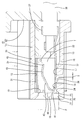
- FIG. 1 is a front view of the connector of the first embodiment.
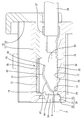
- FIG. 2 is a side sectional view showing a state in which the detection pin inserted into the detection hole is in contact with the front plate portion of the terminal fitting.
- FIG. 3 is a side sectional view showing a state in which the detection pin pushes the terminal fitting backward and moves it.
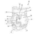
- FIG. 4 is a perspective view of the terminal fitting.
- FIG. 5 is a front sectional view showing a state in which the detection pin is in contact with the front plate portion of the terminal fitting.
- FIG. 6 is a front view of the terminal fitting of the second embodiment.
- FIG. 7 is a perspective view of the terminal fitting of the third embodiment.
- FIG. 8 is a front view of the terminal fitting of the fourth embodiment.
- the connectors of this disclosure are (1) A housing having a terminal accommodating chamber, a tubular portion, and a terminal fitting having an elastic contact piece accommodated in the tubular portion and inserted into the terminal accommodating chamber, and a front wall portion of the housing. Is formed with a tab insertion hole in which the tab of the mating terminal enters the tubular portion from the front and is inserted so as to come into contact with the elastic contact piece, and the terminal fitting is in front of the elastic contact piece.
- the front plate portion is formed, and a detection hole opened separately from the tab insertion hole is formed in the front wall portion of the housing, and the detection hole is the same as the front plate portion in the front wall portion. It is arranged in the opposite position.
- the detection pin is inserted into the detection hole and brought into contact with the front plate portion. Since the front plate portion is located in front of the elastic contact piece, there is no possibility that the detection pin will come into contact with the elastic contact piece. Since the detection hole is opened separately from the tab insertion hole and the tab insertion hole and the detection hole do not communicate with each other, the detection pin inserted into the detection hole may mistakenly enter the tab insertion hole and come into contact with the elastic contact piece. Absent. Therefore, according to the connector of the present disclosure, it is possible to prevent damage or deformation of the elastic contact piece due to the contact of the detection pin.
- the front plate portion extends in a cantilever shape from the plate-shaped portion constituting the tubular portion, and the detection hole is at the center of a cross section orthogonal to the approach direction of the tab in the tubular portion. It is preferable that the plates are arranged eccentrically toward the plate-shaped portion. According to this configuration, since the detection hole is eccentric from the center of the cross section orthogonal to the approach direction of the tab in the tubular portion, that is, from the center of the tubular portion in front view to the plate-shaped portion side, the detection pin is the front plate portion. Of the front plate portion, the portion on the base end side connected to the plate-shaped portion is pushed, not the portion close to the extending end portion. Therefore, the front plate portion is not likely to be deformed backward even if it is pushed by the detection pin.
- the detection hole faces a region of the front plate portion including a base end portion connected to the plate-shaped portion. According to this configuration, the detection pin can push the base end portion of the front plate portion connected to the plate-shaped portion, so that when the front plate portion is pushed by the detection pin, the front plate portion is deformed backward. Can be reliably prevented from doing so.
- the front plate portion covers at least a part of the elastic contact piece from the front. According to this configuration, even when the terminal fitting is located outside the terminal accommodating chamber, damage or deformation of the elastic contact piece due to the interference of foreign matter can be prevented.
- the rear end of the detection hole is opened so as to face the region of the terminal fitting where the front plate portion is not formed in the front-rear direction, and is at least rear of the inner peripheral surface of the detection hole. It is preferable that a guide slope is formed at the end portion so as to approach the front plate portion toward the rear. According to this configuration, the detection pin can be reliably inserted into the detection hole by making the inner diameter of the front end of the detection hole larger than that of the detection pin. The detection pin inserted into the detection hole can be reliably brought into contact with the front plate portion by sliding contact with the guide slope.
- the terminal fitting is held out by an elastically displaceable lance formed in the terminal accommodating chamber, and the guide slope is in a form in which the inner surface of the terminal accommodating chamber is recessed. Is preferable. It is inevitable that a clearance in the front-rear direction will occur between the terminal fitting and the lance that can be elastically displaced, and the terminal fitting can be displaced in the front-rear direction by the amount of this clearance. Focusing on this point, the guide slope has a shape in which the inner surface of the terminal accommodating chamber is recessed. According to this configuration, the detection pin increases the contact area with the front plate portion by sliding contact with the guide slope in the process in which the terminal fitting pressed by the detection pin retracts by the clearance between the detection pin and the lance. Can be made to.
- FIGS. 1 to 5 A first embodiment of the connector of the present disclosure will be described with reference to FIGS. 1 to 5.
- the left side in FIGS. 2 and 3 is defined as the front direction in the front-back direction.
- the directions appearing in FIGS. 1 to 5 are defined as upward and downward as they are.
- the directions appearing in FIGS. 1 and 5 are defined as left and right as they are.
- the connector of the first embodiment includes a housing 10 (see FIGS. 1 and 2) and a plurality of terminal fittings 30 (see FIGS. 2 to 4).
- the housing 10 has a housing body 11 made of synthetic resin and a retainer 12 made of synthetic resin attached to the rear end of the housing body 11, and has a rectangular shape that is long in the left-right direction as a whole.
- a plurality of terminal accommodating chambers 13 elongated in the front-rear direction are formed in the housing 10 in a state of being arranged in the left-right direction.
- the terminal fitting 30 is inserted into each terminal accommodating chamber 13 from the rear of the housing 10.
- the left-right direction and the parallel direction of the terminal accommodating chamber 13 are used interchangeably.
- the housing 10 has a bottom wall portion 15 that constitutes a bottom surface 14 (inner surface according to claim) of the terminal accommodating chamber 13.
- the bottom wall portion 15 is formed with a lance 16 in a cantilevered manner extending forward (in the same direction as the insertion direction of the terminal fitting 30 with respect to the terminal accommodating chamber 13).
- the lance 16 can be elastically displaced in the vertical direction (direction orthogonal to the extending direction of the lance 16) with the rear end portion of the lance 16 as a fulcrum while facing the terminal accommodating chamber 13.
- the front end portion of the lance 16 functions as a retaining portion 17 for retaining the terminal fitting 30.
- the retaining portion 17 is displaced so as to draw an arc.
- the vertical direction and the elastic displacement direction of the lance 16 are used interchangeably.
- the housing 10 has a front wall portion 18 that constitutes a front portion of the terminal accommodating chamber 13.
- the front wall portion 18 is a wall portion of the outer wall portion of the housing 10 that constitutes the front surface of the housing 10.
- the range from the upper surface to the lower surface of the housing 10 in the front surface of the housing 10 is defined as the front wall portion 18.
- the front wall portion 18 extends over a region above the terminal accommodation chamber 13 and a region below the terminal accommodation chamber 13.
- a plurality of tab insertion holes 19 individually facing the plurality of terminal accommodating chambers 13 are formed in the front wall portion 18.
- the tab insertion hole 19 penetrates the front wall portion 18 in the front-rear direction and communicates from the front surface of the housing 10 to the front end of the terminal accommodating chamber 13.
- the tab insertion hole 19 is arranged above the front wall portion 18.
- the tab insertion hole 19 is arranged at the center of the terminal accommodating chamber 13 in the left-right direction.
- the tab T of the mating terminal is inserted into the tab insertion hole 19 from the front of the housing 10.
- a plurality of detection holes 20 individually facing the plurality of terminal accommodating chambers 13 are formed in the front wall portion 18. As shown in FIGS. 2 and 3, the detection hole 20 has a form in which the axial direction is directed in the front-rear direction and the front wall portion 18 is penetrated in the front-rear direction.
- the detection hole 20 communicates the front surface of the housing 10 with the front end of the terminal accommodating chamber 13.
- the detection hole 20 and the tab insertion hole 19 do not directly communicate with each other, and form holes that are independent of each other.
- the detection hole 20 is arranged at a position (lower part of the front wall portion 18) separated downward from the tab insertion hole 19.
- the axis of the detection hole 20 is located at substantially the same height as the bottom surface 14 (upper surface of the bottom wall portion 15) of the terminal accommodating chamber 13. Specifically, the axis of the detection hole 20 is located slightly above the bottom surface 14 of the terminal accommodating chamber 13.
- the detection holes 20 are arranged at positions eccentric to the left with respect to the tab insertion holes 19 in the front view.
- the detection hole 20 has a fixed diameter hole portion 21, an guide portion 22, and a guide hole portion 23.
- the fixed diameter hole portion 21 constitutes most of the region of the detection hole 20.
- the cross-sectional shape of the fixed diameter hole 21 cut at a right angle to the axis is circular.
- the inner diameter of the fixed diameter hole portion 21 has a constant dimension from the front end to the rear end of the fixed diameter hole portion 21.
- the guide portion 22 is connected to the front end of the fixed diameter hole portion 21 and is arranged at the front end of the detection hole 20.
- the guide portion 22 has a tapered shape that expands concentrically with the fixed diameter hole portion 21 toward the front.
- the front end of the guide portion 22 is open to the front surface of the housing 10. That is, the detection hole 20 is circularly opened in the front wall portion 18 (front surface of the housing 10).
- the guide hole portion 23 is connected to the rear end portion of the fixed diameter hole portion 21 and constitutes the rear end portion of the detection hole 20.
- the guide hole portion 23 is arranged only in the region behind the front wall portion 18 (front end of the terminal accommodating chamber 13) in the front-rear direction. Therefore, the formation region of the detection hole 20 in the front-rear direction is a range extending from the front end of the front wall portion 18 to a position rearward from the rear end (front end of the terminal accommodating chamber 13) of the front wall portion 18.
- the cross-sectional shape of the guide hole 23 cut at a right angle to the axis is non-circular.
- the guide hole 23 is opened upward on the bottom surface 14 of the terminal accommodating chamber 13.
- the rear end of the fixed diameter hole portion 21 is opened backward in the front surface of the terminal accommodating chamber 13.
- a guide slope 24 is formed in the lower half region of the inner circumference of the guide hole portion 23 so as to gradually increase toward the rear.
- the guide slope 24 is inclined so that the height difference from the bottom surface 14 of the terminal accommodating chamber 13 becomes smaller toward the rear.
- the guide slope 24 has a shape in which the bottom surface 14 (inner surface) of the terminal accommodating chamber 13 is recessed.
- the terminal fitting 30 is a female terminal having a tubular portion 31 and a crimping portion 37.
- the tubular portion 31 has a substrate portion 32 (lower plate portion), a left side plate portion 33 (plate-shaped portion according to claim), a right side plate portion 34, and an upper plate portion 35. Since the substrate portion 32, the left side plate portion 33, the right side plate portion 34, and the upper plate portion 35 have a flat plate shape, the tubular portion 31 has a square tubular shape with the front end and the rear end opened. That is, the tubular portion 31 is square when the terminal fitting 30 is viewed from the front.
- a protrusion 36 having a shape protruding downward is formed at the front end portion of the substrate portion 32.
- the crimping portion 37 has an open barrel shape and is connected to the rear end of the tubular portion 31.
- the crimping portion 37 is electrically crimped to the front end portion of the electric wire 38.
- the terminal fitting 30 has an elastic contact piece 40.
- the elastic contact piece 40 has a form in which the elastic contact piece 40 is folded backward in an arc from the front end of the substrate portion 32 and extends rearward, and is housed in the box portion.
- the elastic contact piece 40 can be elastically displaced in the vertical direction (direction approaching / separating from the substrate portion 32) with the folded-back portion 41 (front end portion) connected to the substrate portion 32 as a fulcrum.
- the elastic contact piece 40 has a curved portion 42 connected to the rear end of the folded portion 41.
- the curved portion 42 has a shape that protrudes upward so as to move away from the substrate portion 32.
- the upper end portion of the curved portion 42 having the minimum facing distance from the upper plate portion 35 is a contact portion 43 capable of contacting the tab T.
- the terminal fitting 30 has a symmetrical left front plate portion 44 (front plate portion according to claim) and a right front plate portion 45.
- the left front plate portion 44 extends cantileverly to the right from the front end edge of the left plate portion 33 (a plate-shaped portion different from the substrate portion 32 to which the elastic contact pieces 40 are connected) at right angles to the left plate portion 33.
- the right front plate portion 45 extends cantileverly to the right from the front end edge of the right plate portion 34 (a plate-shaped portion different from the substrate portion 32 in which the elastic contact pieces 40 are connected) at right angles to the right plate portion 34. ..
- the left side plate portion 33 and the right side plate portion 34 are arranged side by side with a space between them at the central portion in the left-right direction of the cylinder portion 31. Both the left plate portion 33 and the right plate portion 34 are located in front of the front end (folded portion 41) of the elastic contact piece 40, and protect at least the folded portion 41 of the elastic contact piece 40 from the front. There is.
- the front view shape of the left front plate portion 44 is a square with the long side facing up and down as a whole. Specifically, at the right end (extending end) at the lower edge of the left front plate 44, the protrusion 46 projects downward and flush with the left front plate 44. The lower edge of the protrusion 46 is located at the same height as the lower surface (outer surface) of the substrate portion 32.
- the horizontal dimension of the left front plate portion 44 is slightly smaller than 1/2 of the width dimension of the tubular portion 31.
- the upper edge of the left front plate portion 44 is located below the contact portion 43 of the elastic contact piece 40 and the lower edge of the tab insertion hole 19 (on the substrate portion 32 side).
- the lower end of the base end portion 47 connected to the left side plate portion 33 of the left front plate portion 44 is located above the upper surface of the substrate portion 32.
- the front view shape of the right front plate portion 45 is a square with the long side facing up and down as a whole. Specifically, at the left end portion (extending end portion) of the lower edge of the right front plate portion 45, the protrusion 46 projects downward and flush with the right front plate portion 45. The lower edge of the protrusion 46 is located at the same height as the lower surface (outer surface) of the substrate portion 32. The left-right dimension of the right front plate portion 45 is slightly smaller than 1/2 of the width dimension of the tubular portion 31. The upper edge of the right front plate portion 45 is located below the contact portion 43 of the elastic contact piece 40 and the lower edge of the tab insertion hole 19 (on the substrate portion 32 side). The lower end of the base end portion 47 connected to the right side plate portion 34 of the right front plate portion 45 is located above the upper surface of the substrate portion 32.
- the terminal fitting 30 is inserted into the terminal accommodating chamber 13 from the rear of the housing 10.
- the lance 16 interferes with the protrusion 36 and elastically deforms downward.
- the protrusion 36 passes through the lance 16, so that the lance 16 elastically returns upward and the retaining portion 17 faces the protrusion 36 from behind. Therefore, when the terminal fitting 30 is about to be displaced rearward from the normal insertion position, the terminal fitting 30 is pulled out by the protrusion 36 abutting the retaining portion 17.
- the retaining portion 17 (front end of the lance 16) when the lance 16 is elastically deformed in the process of inserting the terminal fitting 30 is located behind the retaining portion 17 when the lance 16 is not elastically deformed. Therefore, in a state where the terminal fitting 30 is normally inserted and can be removed by the lance 16, a clearance S in the front-rear direction is generated between the protrusion 36 and the retaining portion 17. Therefore, in the terminal fitting 30 in the normally inserted state, the left front plate portion 44 and the right front plate portion 45 are in contact with the front wall portion 18 at the foremost end position (see FIG. 2), and the protrusion 36 is a retaining portion 17 (front end of the lance 16). It is possible to move in the front-rear direction with respect to the housing 10 by the amount of the clearance S between the position and the rearmost position (see FIG. 3).
- the tab T of the mating terminal is inserted into the tubular portion 31 through the tab insertion hole 19 and elastically contacts. While elastically deforming the piece 40 downward, it enters between the contact portion 43 and the upper plate portion 35. As a result, the tab T is sandwiched between the upper plate portion 35 and the contact portion 43 and elastically connected to the terminal fitting 30.
- the positional relationship between the detection hole 20 and the normally inserted terminal fitting 30 is as follows. As shown in FIG. 5, a part of the lower end portion including the protrusion 46 of the left front plate portion 44 and a part of the lower end portion of the right front plate portion 45 are included in the opening region of the fixed diameter hole portion 21 of the detection hole 20. Is arranged.
- the fixed-diameter hole portion 21 of the detection hole 20 faces a region of the left front plate portion 44 including the lower end portion of the base end portion 47 connected to the left plate portion 33.
- the detection hole 20 is eccentric from the right edge portion of the left front plate portion 44 (the tip edge portion in the extending direction from the left plate portion 33 and the central portion in the front view of the tubular portion 31) to the left plate portion 33 side. It faces the part where it was made.
- the rear end of the detection hole 20 is opened so as to face the region of the terminal fitting 30 where the front plate portion is not formed.
- a continuity inspection is performed.
- a rod-shaped detection pin P having a circular cross section is inserted from the front of the housing 10.
- the outer diameter dimension of the detection pin P is smaller than the diameter (inner diameter) of the fixed diameter hole portion 21 and larger than the radius of the fixed diameter hole portion 21.
- a tapered guide portion 22 is formed at the front end portion of the detection hole 20. Therefore, even if the detection pin P is displaced in the vertical and horizontal directions with respect to the detection hole 20, the detection pin P is surely inserted into the detection hole 20.
- the detection pin P inserted into the detection hole 20 advances in the fixed diameter hole portion 21 and comes into contact with the lower end portion of the left front plate portion 44. If the detection circuit is closed when the detection pin P comes into contact with the left front plate portion 44, it is determined that the terminal fitting 30 is inserted into the proper terminal accommodating chamber 13. If the detection circuit is not closed, it is determined that the terminal fitting 30 is not inserted into the proper terminal accommodating chamber 13.
- the terminal fitting 30 retracts by the clearance S between the protrusion 36 and the lance 16, and during this time, the detection pin P moves back on the guide slope. It is in sliding contact with 24. Since the guide slope 24 is inclined so as to approach the left front plate portion 44 from below toward the rear, the detection pin P comes into contact with the left front plate portion 44 as the terminal fitting 30 retracts. The area increases.
- the connector of the first embodiment has a housing 10 having a plurality of terminal accommodating chambers 13 and a plurality of terminal fittings 30 inserted into the terminal accommodating chamber 13.
- the terminal fitting 30 has a tubular portion 31 and an elastic contact piece 40 housed in the tubular portion 31.
- the front wall portion 18 of the housing 10 is formed with a tab insertion hole 19 into which the tab T of the mating terminal is inserted so as to enter the tubular portion 31 from the front and come into contact with the elastic contact piece 40. That is, the tab T inserted into the tab insertion hole 19 from the front of the housing 10 enters the tubular portion 31 and comes into contact with the elastic contact piece 40.
- a left front plate portion 44 is formed in front of the elastic contact piece 40 of the terminal fitting 30.
- a detection hole 20 opened separately from the tab insertion hole 19 is formed in the front wall portion 18 of the housing 10.
- the detection hole 20 is arranged at a position of the front wall portion 18 facing the left front plate portion 44 in the front-rear direction. That is, in front view, the opening of the tab insertion hole 19 and the opening of the detection hole 20 are not directly communicated with each other, but are in a non-communication relationship.
- the detection pin P is inserted into the detection hole 20 and brought into contact with the left front plate portion 44. Since the left front plate portion 44 is located in front of the elastic contact piece 40, there is no possibility that the detection pin P will come into contact with the elastic contact piece 40. Since the detection hole 20 is opened separately from the tab insertion hole 19 and the detection hole 20 and the tab insertion hole 19 are not in communication with each other, the detection pin P inserted into the detection hole 20 erroneously enters the tab insertion hole 19. There is no risk of contact with the elastic contact piece 40. Therefore, according to the connector of the first embodiment, damage or deformation of the elastic contact piece 40 due to the contact of the detection pin P can be prevented.
- the left front plate portion 44 has a cantilevered shape extending from the left plate portion 33 constituting the tubular portion 31.
- the detection holes 20 are arranged eccentrically from the center of the cross section orthogonal to the approach direction of the tab T in the tubular portion 31 (center of the front view of the tubular portion 31) toward the left side plate portion 33.
- the detection pin P pushes not the portion of the left front plate portion 44 near the extending end portion (right end portion) but the portion of the left front plate portion 44 on the base end portion 47 side connected to the left plate portion 33. Therefore, the left front plate portion 44 is not likely to be deformed backward even if it is pushed by the detection pin P.
- the detection hole 20 faces the region of the left front plate portion 44 including the base end portion 47 connected to the left plate portion 33. According to this configuration, since the detection pin P pushes the base end portion 47 connected to the left side plate portion 33 of the left front plate portion 44, when the left front plate portion 44 is pushed by the detection pin P, the left front plate portion 44 Can be reliably prevented from deforming backwards.
- the left front plate portion 44 together with the right front plate portion 45, covers at least a part (folded portion 41) of the elastic contact piece 40 from the front. According to this configuration, even when the terminal fitting 30 is located outside the terminal accommodating chamber 13, damage or deformation of the elastic contact piece 40 (particularly, the folded-back portion 41) due to interference of foreign matter can be prevented.
- the folded-back portion 41 is an important portion for defining the elastic restoring force of the elastic contact piece 40, that is, the contact pressure with the tab T. Therefore, by covering and protecting the folded-back portion 41 with the left front plate portion 44 and the right front plate portion 45, it is possible to prevent the function of the terminal fitting 30 from being impaired.
- the detection pin P Since the inner diameter of the front end of the detection hole 20 is set to a size larger than the outer diameter of the detection pin P, the detection pin P can be reliably inserted into the detection hole 20.
- the rear end of the detection hole 20 is a region of the front end portion of the terminal fitting 30 in which the left front plate portion 44 is not formed, that is, a region below the base end portion 47 of the left front plate portion 44 (in FIG. 5).
- the quadrant arc portion in the lower left corner of the tubular portion 31) is opened so as to face in the front-rear direction. Therefore, there is a concern that the contact area between the detection pin P and the left front plate portion 44 cannot be sufficiently secured.
- a guide slope 24 is formed at the rear end portion (guide hole portion 23) of the inner peripheral surface of the detection hole 20 so as to approach the left front plate portion 44 toward the rear. Has been done. According to this configuration, the detection pin P inserted into the detection hole 20 can be surely brought into contact with the left front plate portion 44 by sliding contact with the guide slope 24.
- the terminal fitting 30 is held out by an elastically displaceable lance 16 formed in the terminal accommodating chamber 13. Therefore, it is inevitable that a clearance S in the front-rear direction is generated between the terminal fitting 30 and the elastically displaceable lance 16, and the terminal fitting 30 can be displaced in the front-rear direction by the amount of this clearance S.
- the guide slope 24 has a shape in which the inner surface of the terminal accommodating chamber 13 is recessed. According to this configuration, in the process in which the terminal fitting 30 pressed by the detection pin P retracts by the clearance S between the detection pin P and the lance 16, the detection pin P slides into contact with the guide slope 24 to form the left front plate portion. The contact area with 44 can be increased.
- Example 2 embodying the present disclosure will be described with reference to FIG.
- the left front plate portion 51 plate-shaped portion according to the claim
- the right front plate portion 52 of the terminal fitting 50 have different configurations from those of the first embodiment. Since other configurations are the same as those in the first embodiment, the same configurations are designated by the same reference numerals, and the description of the structure, action, and effect will be omitted.
- the left front plate portion 51 extends from the front end edge of the left plate portion 33 to the right at right angles to the left plate portion 33 in a cantilever shape.
- the right front plate portion 52 extends from the front end edge of the right plate portion 34 to the left at right angles to the right plate portion 34 in a cantilever shape.
- the extension dimension of the left front plate portion 51 from the left plate portion 33 is smaller than the extension dimension of the right front plate portion 52 from the right plate portion 34. That is, the left front plate portion 51 and the right front plate portion 52 are asymmetrical.
- the left side plate portion 33 and the right side plate portion 34 are arranged side by side with a gap from each other on the left side of the center of the cylinder portion 31 in the left-right direction.
- a part of the lower end portion of the left front plate portion 51 and a part of the lower end portion of the right front plate portion 52 are arranged in the opening region of the fixed diameter hole portion 21 of the detection hole 20.
- the fixed-diameter hole portion 21 of the detection hole 20 faces a region of the left front plate portion 51 including the lower end portion of the base end portion 47 connected to the left plate portion 33.
- the area occupied by the left front plate portion 51 is larger than the area occupied by the right front plate portion 52.
- the extension dimension of the left front plate portion 51 from the left plate portion 33 is smaller than that of the first embodiment. Therefore, when the detection pin P pushes the left front plate portion 51, the left front plate portion 51 is less likely to be deformed rearward.
- Example 3 which embodies the present disclosure, will be described with reference to FIG.
- the front plate portion 56 of the terminal fitting 55 has a configuration different from that of the first embodiment. Since other configurations are the same as those in the first embodiment, the same configurations are designated by the same reference numerals, and the description of the structure, action, and effect will be omitted.
- the number of front plate portions 56 included in the terminal fitting 55 of the third embodiment is only one.
- the front plate portion 56 extends from the front end edge of the left plate portion 33 to the right at right angles to the left plate portion 33 in a cantilever shape.
- the extending end edge portion (right end edge portion) of the front plate portion 56 approaches and faces the front end edge of the right side plate portion 34 from the front, or covers the front end edge of the right side plate portion 34 from the front. Is in contact with.
- the front plate portion 56 is supported by the tubular portion 31 at two locations, a base end portion 57 (left end edge portion) and an extension end portion (right end edge portion). Therefore, even if the detection pin P pushes the front plate portion 56 rearward, there is no possibility that the front plate portion 56 is deformed rearward.
- Example 4 which embodies the present disclosure, will be described with reference to FIG.
- the left front plate portion 61 the plate-shaped portion according to the claim
- the right front plate portion 62 of the terminal fitting 60 have a configuration different from that of the first embodiment. Since other configurations are the same as those in the first embodiment, the same configurations are designated by the same reference numerals, and the description of the structure, action, and effect will be omitted.
- the left front plate portion 61 extends cantileverly to the right from the front end edge of the left plate portion 33 at right angles to the left plate portion 33.
- the right front plate portion 62 extends from the front end edge of the right plate portion 34 to the left at right angles to the right plate portion 34 in a cantilever shape.
- the extension dimension of the left front plate portion 61 from the left plate portion 33 is larger than 1/2 of the width dimension of the tubular portion 31.
- the extension dimension of the right front plate portion 62 from the right plate portion 34 is also larger than 1/2 of the width dimension of the tubular portion 31.
- the left front plate portion 61 is formed with a fitting recess 63 having a laterally T-shaped shape when viewed from the front.
- the right front plate portion 62 is formed with a fitting convex portion 64 having a laterally T-shaped shape when viewed from the front. Since the fitting recess 63 and the fitting protrusion 64 are fitted to each other, the left front plate portion 61 and the right front plate portion 62 are restricted from being displaced in the vertical direction and the horizontal direction.
- the fixed-diameter hole portion 21 of the detection hole 20 faces a region of the left front plate portion 61 including the lower end portion of the base end portion 65 connected to the left plate portion 33.
- the area occupied by the left front plate portion 61 in the opening region of the fixed diameter hole portion 21 is larger than the area occupied by the right front plate portion 62.
- the detection hole faces the portion of the front plate portion that is eccentric from the center of the front plate portion to the plate-like portion side, but the detection hole is the tubular portion of the front plate portion. It may face a portion located in the center of the front view of the.
- the elastic contact piece extends from the substrate portion in a folded shape, and the front plate portion extends from a plate-shaped portion different from the substrate portion, but the front plate portion extends from the substrate portion.
- the detection hole faces the region of the front plate portion including the base end portion connected to the plate-shaped portion, but the detection hole is separated from the base end portion of the front plate portion. It may face only the area.
- the front plate portion covers at least a part of the elastic contact piece from the front, but the front plate portion may have a form that does not cover the elastic contact piece from the front. ..
- the rear end of the detection hole is opened so as to face the region of the terminal fitting where the front plate portion is not formed, but the rear end of the detection hole is of the terminal fitting.
- the opening may be made so as not to face the region where the front plate portion is not formed but to face only the front plate portion.
- the guide slope is formed on the inner circumference of the detection hole, but the detection hole may be in a form in which the guide slope is not formed.
- the guide slope is formed only in the region on the rear end side of the detection hole, but the guide slope may be formed over the entire region from the front end to the rear end of the detection hole. Often, it may be formed only in the region on the front end side of the detection hole.
- the guide slope is a form in which the inner surface of the terminal accommodation chamber is recessed, but the guide slope does not recess the inner surface of the terminal accommodation chamber, and only the region in front of the front end of the terminal accommodation chamber is formed. It may be formed in.
- the tubular portion has a square tubular shape having four flat plate portions, but the tubular portion may have a shape having a curved plate portion.
Landscapes
- Physics & Mathematics (AREA)
- General Physics & Mathematics (AREA)
- Connector Housings Or Holding Contact Members (AREA)
- Details Of Connecting Devices For Male And Female Coupling (AREA)
- Testing Of Short-Circuits, Discontinuities, Leakage, Or Incorrect Line Connections (AREA)
- Manufacturing Of Electrical Connectors (AREA)
Abstract
端子金具の損傷や変形を防止する。 コネクタは、端子収容室(13)を有するハウジング(10)と、筒部(31)と、筒部(31)内に収容された弾性接触片(40)とを有し、端子収容室(13)に挿入された端子金具(30)とを備え、ハウジング(10)の前壁部(18)には、相手側端子のタブ(T)が前方から筒部(31)内に進入して弾性接触片(40)と接触するように挿入されるタブ挿入孔(19)が形成され、端子金具(30)のうち弾性接触片(40)よりも前方には、左前板部(44)が形成され、ハウジング(10)の前壁部(18)には、タブ挿入孔(19)とは別に開口した検知孔(20)が形成され、検知孔(20)は、前壁部(18)における左前板部(44)との対向位置に設けられている。
Description
本開示は、コネクタに関するものである。
特許文献1には、コネクタハウジングの端子収容室内に端子金具を挿入したコネクタが開示されている。コネクタハウジングの前壁部には、相手側端子のタブを端子収容室に挿入させるための挿入孔が開口している。挿入孔に挿入されたタブは、端子金具の前端部の電気接触部に接触するようになっている。
特許文献1のコネクタにおいて導通検査を行う際には、検査ピンを挿入孔に挿入し、検査ピンの先端を電気接触部に突き当てるようになっている。電気接触部は、端子金具としての機能上、重要な部位である。そのため、電気接触部に検査ピンを突き当てると、電気接触部が変形し、端子金具が本来の機能を発揮できなくなることが懸念される。
本開示のコネクタは、上記のような事情に基づいて完成されたものであって、端子金具の損傷や変形を防止することを目的とする。
本開示のコネクタは、
端子収容室を有するハウジングと、
筒部と、前記筒部内に収容された弾性接触片とを有し、前記端子収容室に挿入された端子金具とを備え、
前記ハウジングの前壁部には、相手側端子のタブが前方から前記筒部内に進入して前記弾性接触片と接触するように挿入されるタブ挿入孔が形成され、
前記端子金具のうち前記弾性接触片よりも前方には、前板部が形成され、
前記ハウジングの前記前壁部には、前記タブ挿入孔とは別に開口した検知孔が形成され、
前記検知孔は、前記前壁部における前板部との対向位置に配されている。
端子収容室を有するハウジングと、
筒部と、前記筒部内に収容された弾性接触片とを有し、前記端子収容室に挿入された端子金具とを備え、
前記ハウジングの前壁部には、相手側端子のタブが前方から前記筒部内に進入して前記弾性接触片と接触するように挿入されるタブ挿入孔が形成され、
前記端子金具のうち前記弾性接触片よりも前方には、前板部が形成され、
前記ハウジングの前記前壁部には、前記タブ挿入孔とは別に開口した検知孔が形成され、
前記検知孔は、前記前壁部における前板部との対向位置に配されている。
本開示によれば、端子金具の損傷や変形を防止することができる。
[本開示の実施形態の説明]
最初に本開示の実施形態を列記して説明する。
本開示のコネクタは、
(1)端子収容室を有するハウジングと、筒部と、前記筒部内に収容された弾性接触片とを有し、前記端子収容室に挿入された端子金具とを備え、前記ハウジングの前壁部には、相手側端子のタブが前方から前記筒部内に進入して前記弾性接触片と接触するように挿入されるタブ挿入孔が形成され、前記端子金具のうち前記弾性接触片よりも前方には、前板部が形成され、前記ハウジングの前記前壁部には、前記タブ挿入孔とは別に開口した検知孔が形成され、前記検知孔は、前記前壁部における前記前板部との対向位置に配されている。
最初に本開示の実施形態を列記して説明する。
本開示のコネクタは、
(1)端子収容室を有するハウジングと、筒部と、前記筒部内に収容された弾性接触片とを有し、前記端子収容室に挿入された端子金具とを備え、前記ハウジングの前壁部には、相手側端子のタブが前方から前記筒部内に進入して前記弾性接触片と接触するように挿入されるタブ挿入孔が形成され、前記端子金具のうち前記弾性接触片よりも前方には、前板部が形成され、前記ハウジングの前記前壁部には、前記タブ挿入孔とは別に開口した検知孔が形成され、前記検知孔は、前記前壁部における前記前板部との対向位置に配されている。
本開示の構成によれば、導通検査の際には、検知ピンを検知孔に挿入して前板部に接触させる。前板部は弾性接触片よりも前方に位置しているので、検知ピンが弾性接触片に接触するおそれはない。検知孔はタブ挿入孔とは別に開口し、タブ挿入孔と検知孔が連通していないので、検知孔に挿入した検知ピンが、タブ挿入孔に誤進入して弾性接触片と接触するおそれもない。したがって、本開示のコネクタによれば、検知ピンの接触に起因する弾性接触片の損傷や変形を防止できる。
(2)前記前板部が、前記筒部を構成する板状部から片持ち状に延出した形態であり、前記検知孔が、前記筒部における前記タブの進入方向と直交する断面の中央から前記板状部側へ偏心して配されていることが好ましい。この構成によれば、検知孔が、筒部における前記タブの進入方向と直交する断面の中央、即ち筒部の正面視中央から板状部側へ偏心しているので、検知ピンは、前板部のうち延出端部に近い部位ではなく、前板部のうち板状部に連なる基端部側の部位を押す。したがって、前板部は、検知ピンに押されても後方へ変形するおそれがない。
(3)(2)において、前記検知孔が、前記前板部のうち前記板状部に連なる基端部を含む領域と対向していることが好ましい。この構成によれば、検知ピンが、前板部のうち板状部に連なる基端部を押すことができるので、前板部が検知ピンに押されたときに、前板部が後方へ変形することを確実に防止できる。
(4)前記前板部が、前記弾性接触片の少なくとも一部を前方から覆う形態であることが好ましい。この構成によれば、端子金具が端子収容室の外部に位置する状態においても、異物の干渉に起因する弾性接触片の損傷や変形を防止できる。
(5)前記検知孔の後端が、前記端子金具のうち前記前板部が形成されていない領域と前後方向に対向するように開口しており、前記検知孔の内周面のうち少なくとも後端部には、後方に向かうほど前記前板部に接近するように傾斜したガイド斜面が形成されていることが好ましい。この構成によれば、検知孔の前端の内径を検知ピンより大きくすることにより、検知ピンを検知孔内に確実に挿入させることができる。検知孔に挿入された検知ピンは、ガイド斜面に摺接させることによって前板部に確実に接触させることができる。
(6)(5)において、前記端子金具は、前記端子収容室に形成した弾性変位可能なランスによって抜止めされており、前記ガイド斜面が前記端子収容室の内面を凹ませた形態であることが好ましい。端子金具と弾性変位可能なランスとの間には、前後方向のクリアランスが生じることが避けられず、このクリアランスの分だけ、端子金具は前後方向に変位可能である。この点に着目し、ガイド斜面は、端子収容室の内面を凹ませた形態となっている。この構成によれば、検知ピンで押された端子金具が、ランスとの間のクリアランスの分だけ後退する過程において、検知ピンは、ガイド斜面に摺接することにより前板部との接触面積を増大させることができる。
[本開示の実施形態の詳細]
[実施例1]
本開示のコネクタを具体化した実施例1を、図1~図5を参照して説明する。本実施例1において、前後の方向については、図2,3における左方を前方と定義する。上下の方向については、図1~5にあらわれる向きを、そのまま上方、下方と定義する。左右の方向については、図1,5にあらわれる向きを、そのまま左方、右方と定義する。
[実施例1]
本開示のコネクタを具体化した実施例1を、図1~図5を参照して説明する。本実施例1において、前後の方向については、図2,3における左方を前方と定義する。上下の方向については、図1~5にあらわれる向きを、そのまま上方、下方と定義する。左右の方向については、図1,5にあらわれる向きを、そのまま左方、右方と定義する。
本実施例1のコネクタは、ハウジング10(図1,2参照)と、複数の端子金具30(図2~4参照)とを備えている。ハウジング10は、合成樹脂製のハウジング本体11と、ハウジング本体11の後端部に取り付けた合成樹脂製のリテーナ12とを有し、全体として左右方向に長い直方形をなす。ハウジング10内には、前後方向に細長い複数の端子収容室13が、左右方向に並んだ状態で形成されている。各端子収容室13は、ハウジング10の後方から端子金具30が挿入されるようになっている。尚、以下の説明において、左右方向と端子収容室13の並列方向は、同義で用いる。
図2,3に示すように、ハウジング10は、端子収容室13の底面14(請求項に記載の内面)を構成する底壁部15を有する。底壁部15には、前方(端子収容室13に対する端子金具30の挿入方向と同じ方向)へ片持ち状に延出した形態のランス16が形成されている。ランス16は、端子収容室13に臨んだ状態で、ランス16の後端部を支点として上下方向(ランス16の延出方向と直交する方向)に弾性変位し得るようになっている。ランス16の前端部は、端子金具30を抜止めするための抜止部17として機能する。ランス16が上下方向へ弾性変位すると、抜止部17は円弧を描くように変位する。尚、以下の説明において、上下方向とランス16の弾性変位方向は、同義で用いる。
ハウジング10は、端子収容室13の前面部を構成する前壁部18を有する。本実施例1において、前壁部18は、ハウジング10の外壁部のうちハウジング10の前面を構成する壁部である。本実施例1では、ハウジング10の前面のうちハウジング10の上面から下面に至る範囲を、前壁部18と定義する。前壁部18は、端子収容室13よりも上方の領域及び端子収容室13よりも下方の領域に亘っている。
前壁部18には、複数の端子収容室13と個別に対向する複数のタブ挿入孔19が形成されている。タブ挿入孔19は、前壁部18を前後方向に貫通し、ハウジング10の前面から端子収容室13の前端まで連通している。上下方向において、タブ挿入孔19は前壁部18の上部に配されている。図5に想像線で示すように、左右方向において、タブ挿入孔19は、端子収容室13の左右方向中央に配されている。図2に示すように、タブ挿入孔19には、相手側端子のタブTがハウジング10の前方から挿入されるようになっている。
前壁部18には、複数の端子収容室13と個別に対向する複数の検知孔20が形成されている。図2,3に示すように、検知孔20は、軸線方向を前後方向に向け、前壁部18を前後方向に貫通した形態である。検知孔20は、ハウジング10の前面と端子収容室13の前端とを連通させる。検知孔20とタブ挿入孔19は、直接的には連通しておらず、互いに独立した孔部を構成している。
上下方向において、検知孔20は、タブ挿入孔19から下方へ離間した位置(前壁部18の下部)に配されている。検知孔20の軸線は、端子収容室13の底面14(底壁部15の上面)と概ね同じ高さに位置する。詳細には、検知孔20の軸線は、端子収容室13の底面14よりも僅かに上方に位置する。図1,5に示すように、正面視において、検知孔20は、タブ挿入孔19に対して左方へ偏心した位置に配されている。
図2,3に示すように、検知孔20は、定径孔部21と誘導部22とガイド孔部23とを有する。定径孔部21は、検知孔20の大部分の領域を構成している。定径孔部21を軸線と直角に切断した断面形状は、円形である。定径孔部21の内径は、定径孔部21の前端から後端まで一定の寸法である。誘導部22は、定径孔部21の前端に連なり、検知孔20の前端部に配されている。誘導部22は、前方に向かって定径孔部21と同心円状に拡径したテーパ状をなす。誘導部22の前端はハウジング10の前面に開口している。即ち、検知孔20は、前壁部18(ハウジング10の前面)において円形に開口している。
ガイド孔部23は、定径孔部21の後端に連なり、検知孔20の後端部を構成している。ガイド孔部23は、前後方向において前壁部18(端子収容室13の前端)よりも後方の領域のみに配されている。したがって、前後方向における検知孔20の形成領域は、前壁部18の前端から、前壁部18の後端(端子収容室13の前端)よりも後方の位置に至る範囲である。
検知孔20の軸線は端子収容室13の底面14より少し上方の位置に配されているので、ガイド孔部23を軸線と直角に切断した断面形状は、非円形である。ガイド孔部23は、端子収容室13の底面14において上向きに開口している。定径孔部21の後端は、端子収容室13の前面において後向きに開口している。ガイド孔部23の内周のうち下半分の領域には、後方に向かって次第に高くなるように傾斜したガイド斜面24が形成されている。ガイド斜面24は、後方に向かうほど端子収容室13の底面14との高低差が小さくなるような形態で傾斜している。ガイド斜面24は、端子収容室13の底面14(内面)を凹ませた形態である。
図2~4に示すように、端子金具30は、筒部31と圧着部37とを有する雌型の端子である。筒部31は、基板部32(下板部)と左側板部33(請求項に記載の板状部)と右側板部34と上板部35とを有する。基板部32と左側板部33と右側板部34と上板部35は平板状をなすので、筒部31は、前端と後端が開口された角筒状をなしている。つまり、端子金具30を前方から視た正面視において、筒部31は方形をなす。基板部32の前端部には、下方(筒部31の外面側)へ突出した形態の突起部36が形成されている。圧着部37は、オープンバレル状をなし、筒部31の後端に連なっている。圧着部37は、電線38の前端部に導通可能に圧着されている。
図2,3に示すように、端子金具30は弾性接触片40を有している。弾性接触片40は、基板部32の前端から弧を描いて後方へ折り返し、後方へ延出した形態であり、箱部内に収容されている。弾性接触片40は、基板部32に繋がる折返部41(前端部)を支点として上下方向(基板部32に対して接近・離間する方向)へ弾性変位し得るようになっている。弾性接触片40は、折返部41の後端に連なる湾曲部42を有する。湾曲部42は、基板部32から遠ざかるように上向きに突出した形状である。湾曲部42のうち上板部35との対向間隔が最小となる上端部は、タブTと接触可能な接点部43となっている。
図4,5に示すように、端子金具30は、左右対称な左前板部44(請求項に記載の前板部)と右前板部45とを有する。左前板部44は、左側板部33(弾性接触片40が連なる基板部32とは別の板状部)の前端縁から左側板部33と直角に右方へ片持ち状に延出している。右前板部45は、右側板部34(弾性接触片40が連なる基板部32とは別の板状部)の前端縁から右側板部34と直角に右方へ片持ち状に延出している。正面視において、左側板部33と右側板部34は、筒部31の左右方向中央部で互いに間隔を空けて左右に並んでいる。左側板部33と右側板部34は、いずれも、弾性接触片40の前端(折返部41)よりも前方に位置し、弾性接触片40の少なくとも折返部41を前方から覆うように保護している。
左前板部44の正面視形状は、全体として長辺を上下方向に向けた方形をなす。詳細には、左前板部44の下縁における右端部(延出端部)には、突部46が下向きに且つ左前板部44と面一状に突出している。突部46の下縁は、基板部32の下面(外面)と同じ高さに位置する。左前板部44の左右方向の寸法は、筒部31の幅寸法の1/2よりも少し小さい寸法である。左前板部44の上縁は、弾性接触片40の接点部43及びタブ挿入孔19の下縁よりも下方(基板部32側)に位置する。左前板部44のうち左側板部33に連なる基端部47の下端は、基板部32の上面よりも上方に位置する。
右前板部45の正面視形状は、全体として長辺を上下方向に向けた方形をなす。詳細には、右前板部45の下縁における左端部(延出端部)には、突部46が下向きに且つ右前板部45と面一状に突出している。突部46の下縁は、基板部32の下面(外面)と同じ高さに位置する。右前板部45の左右方向の寸法は、筒部31の幅寸法の1/2よりも少し小さい寸法である。右前板部45の上縁は、弾性接触片40の接点部43及びタブ挿入孔19の下縁よりも下方(基板部32側)に位置する。右前板部45のうち右側板部34に連なる基端部47の下端は、基板部32の上面よりも上方に位置する。
端子金具30は、ハウジング10の後方から端子収容室13内に挿入されている。端子金具30の挿入過程では、ランス16が突起部36と干渉して下方へ弾性変形する。端子金具30が正規位置まで挿入されると、突起部36がランス16を通過するので、ランス16が上方へ弾性復帰し、抜止部17が突起部36に対して後方から対向する。したがって、端子金具30が正規挿入位置から後方へ変位しようとしたときには、突起部36が抜止部17に突き当たることによって、端子金具30が抜止めされる。
端子金具30の挿入過程でランス16が弾性変形したときの抜止部17(ランス16の前端)は、ランス16が弾性変形していないときの抜止部17よりも後方に位置する。したがって、端子金具30が、正規挿入されてランス16により抜止め可能とされている状態では、突起部36と抜止部17との間には前後方向のクリアランスSが生じる。そのため、正規挿入状態の端子金具30は、左前板部44と右前板部45を前壁部18に当たる最前端位置(図2を参照)と、突起部36が抜止部17(ランス16の前端)に当たる最後端位置(図3を参照)との間で上記クリアランスSの分だけハウジング10に対して前後方向に移動可能である。
端子金具30が正規挿入されたコネクタと、相手側コネクタ(図示省略)とが嵌合すると、相手側端子のタブTが、タブ挿入孔19を貫通して筒部31内に挿入され、弾性接触片40を下方へ弾性変形させながら接点部43と上板部35との間に進入する。これにより、タブTが、上板部35と接点部43との間に挟まれて、端子金具30と弾性的に接続される。
検知孔20と、正規挿入された端子金具30との位置関係は、次の通りである。図5に示すように、検知孔20の定径孔部21の開口領域内には、左前板部44の突部46を含む下端部の一部と、右前板部45の下端部の一部が配されている。検知孔20の定径孔部21は、左前板部44のうち左側板部33に連なる基端部47の下端部を含む領域と対向している。換言すると、検知孔20は、左前板部44のうち右側縁部(左側板部33からの延出方向先端縁部であり、筒部31の正面視中央部)から左側板部33側へ偏心した部位と対向している。検知孔20の後端は、端子金具30のうち前板部が形成されていない領域にも対向するように開口している。
端子金具30を端子収容室13に挿入した後は、導通検査が行われる。導通検査の際には、ハウジング10の前方から円形断面の棒状をなす検知ピンPが挿入される。検知ピンPの外径寸法は、定径孔部21の直径(内径)よりも小さく、定径孔部21の半径よりも大きい。また、検知孔20の前端部にはテーパ状の誘導部22が形成されている。したがって、検知ピンPが検知孔20に対して上下左右方向へ位置ずれしても、検知ピンPは確実に検知孔20内に挿入される。
検知孔20に挿入された検知ピンPは、定径孔部21内を進み、左前板部44の下端部に接触する。検知ピンPが左前板部44に接触したときに、検知回路が閉成されると、端子金具30が適正な端子収容室13に挿入されていると判断される。検知回路が閉成されない場合は、端子金具30が適正な端子収容室13に挿入されていないと判断される。
検知ピンPを検知孔20に挿入して左前板部44を押すと、端子金具30が、突起部36とランス16との間のクリアランスS分だけ後退し、この間に、検知ピンPがガイド斜面24に摺接する。ガイド斜面24は、後方に向かうほど左前板部44に対して下から接近するように傾斜しているので、端子金具30が後退するのに伴って、検知ピンPと左前板部44との接触面積が増大する。
本実施例1のコネクタは、複数の端子収容室13を有するハウジング10と、端子収容室13に挿入された複数の端子金具30を有する。端子金具30は、筒部31と、筒部31内に収容された弾性接触片40とを有する。ハウジング10の前壁部18には、相手側端子のタブTが前方から筒部31内に進入して弾性接触片40と接触するように挿入されるタブ挿入孔19が形成されている。即ち、ハウジング10の前方からタブ挿入孔19に挿入されたタブTは、筒部31内に進入して弾性接触片40と接触するようになっている。端子金具30のうち弾性接触片40よりも前方には、左前板部44が形成されている。ハウジング10の前壁部18には、タブ挿入孔19とは別に開口した検知孔20が形成されている。検知孔20は、前壁部18のうち左前板部44と前後方向に対向する位置に配されている。即ち、正面視において、タブ挿入孔19の開口部と検知孔20の開口部とは、直接的に連通しておらず、非連通の関係である。
本実施例1のコネクタによれば、導通検査の際には、検知ピンPを検知孔20に挿入して左前板部44に接触させる。左前板部44は弾性接触片40よりも前方に位置しているので、検知ピンPが弾性接触片40に接触するおそれはない。検知孔20は、タブ挿入孔19とは別に開口しており、検知孔20とタブ挿入孔19は互いに非連通なので、検知孔20に挿入した検知ピンPが、タブ挿入孔19に誤進入して弾性接触片40と接触するおそれもない。したがって、本実施例1のコネクタによれば、検知ピンPの接触に起因する弾性接触片40の損傷や変形を防止できる。
左前板部44は、筒部31を構成する左側板部33から片持ち状に延出した形態である。この形態に鑑み、検知孔20は、筒部31におけるタブTの進入方向と直交する断面の中央(筒部31の正面視中央)から左側板部33側へ偏心して配されている。これにより、検知ピンPは、左前板部44のうち延出端部(右端部)に近い部位ではなく、左前板部44のうち左側板部33に連なる基端部47側の部位を押す。したがって、左前板部44は、検知ピンPに押されても後方へ変形するおそれがない。
検知孔20は、左前板部44のうち左側板部33に連なる基端部47を含む領域と対向している。この構成によれば、検知ピンPが、左前板部44のうち左側板部33に連なる基端部47を押すので、左前板部44が検知ピンPに押されたときに、左前板部44が後方へ変形することを確実に防止できる。
左前板部44は、右前板部45とともに、弾性接触片40の少なくとも一部(折返部41)を前方から覆う形態である。この構成によれば、端子金具30が端子収容室13の外部に位置する状態においても、異物の干渉に起因する弾性接触片40(特に、折返部41)の損傷や変形を防止できる。折返部41は、弾性接触片40の弾性復元力、即ちタブTとの接触圧を規定するための重要な部位である。したがって、折返部41を左前板部44と右前板部45で覆って保護することにより、端子金具30の機能が損なわれることを防止できる。
検知孔20の前端の内径は、検知ピンPの外径よりも大きい寸法に設定されているので、検知ピンPを検知孔20内に確実に挿入させることができるようになっている。その一方で、検知孔20の後端は、端子金具30の前端部のうち左前板部44が形成されていない領域、即ち左前板部44の基端部47よりも下方の領域(図5において、筒部31の左下隅の四半円弧部)に対して前後方向に対向するように開口している。そのため、検知ピンPと左前板部44との接触面積が十分に確保できなくなることが懸念される。
そこで、本実施例1では、検知孔20の内周面の後端部(ガイド孔部23)に、後方に向かうほど左前板部44に接近するように斜め上向きに傾斜したガイド斜面24が形成されている。この構成によれば、検知孔20に挿入された検知ピンPは、ガイド斜面24に摺接させることによって左前板部44に確実に接触させることができる。
端子金具30は、端子収容室13に形成した弾性変位可能なランス16によって抜止めされている。そのため、端子金具30と弾性変位可能なランス16との間には、前後方向のクリアランスSが生じることが避けられず、このクリアランスSの分だけ、端子金具30は前後方向に変位可能である。この点に鑑み、ガイド斜面24は、端子収容室13の内面を凹ませた形態となっている。この構成によれば、検知ピンPで押された端子金具30が、ランス16との間のクリアランスSの分だけ後退する過程において、検知ピンPは、ガイド斜面24に摺接することにより左前板部44との接触面積を増大させることができる。
[実施例2]
本開示を具体化した実施例2を、図6を参照して説明する。本実施例2は、端子金具50の左前板部51(請求項に記載の板状部)と右前板部52を上記実施例1とは異なる構成としたものである。その他の構成については上記実施例1と同じであるため、同じ構成については、同一符号を付し、構造、作用及び効果の説明は省略する。
本開示を具体化した実施例2を、図6を参照して説明する。本実施例2は、端子金具50の左前板部51(請求項に記載の板状部)と右前板部52を上記実施例1とは異なる構成としたものである。その他の構成については上記実施例1と同じであるため、同じ構成については、同一符号を付し、構造、作用及び効果の説明は省略する。
左前板部51は、左側板部33の前端縁から左側板部33と直角に右方へ片持ち状に延出している。右前板部52は、右側板部34の前端縁から右側板部34と直角に左方へ片持ち状に延出している。左側板部33からの左前板部51の延出寸法は、右側板部34からの右前板部52の延出寸法よりも小さい。即ち、左前板部51と右前板部52は、左右非対称である。左側板部33と右側板部34は、筒部31の左右方向中央よりも左方において、互いに間隔を空けて左右に並んでいる。
検知孔20の定径孔部21の開口領域内には、左前板部51の下端部の一部と、右前板部52の下端部の一部が配されている。検知孔20の定径孔部21は、左前板部51のうち左側板部33に連なる基端部47の下端部を含む領域と対向している。定径孔部21の開口領域内において、左前板部51が占める面積は、右前板部52が占める面積よりも大きい。しかし、左前板部51の左側板部33からの延出寸法は、実施例1に比べて小さい。したがって、検知ピンPが左前板部51を押したときに、左前板部51が後方へ変形し難くなっている。
[実施例3]
本開示を具体化した実施例3を、図7を参照して説明する。本実施例3は、端子金具55の前板部56を上記実施例1とは異なる構成としたものである。その他の構成については上記実施例1と同じであるため、同じ構成については、同一符号を付し、構造、作用及び効果の説明は省略する。
本開示を具体化した実施例3を、図7を参照して説明する。本実施例3は、端子金具55の前板部56を上記実施例1とは異なる構成としたものである。その他の構成については上記実施例1と同じであるため、同じ構成については、同一符号を付し、構造、作用及び効果の説明は省略する。
本実施例3の端子金具55が有する前板部56の数は、1枚だけである。前板部56は、左側板部33の前端縁から左側板部33と直角に右方へ片持ち状に延出している。前板部56の延出端縁部(右端縁部)は、右側板部34の前端縁に対して前方から接近して対向し、又は右側板部34の前端縁に対して前方から覆うように接触している。前板部56は、基端部57(左端縁部)と延出端部(右端縁部)の2箇所で、筒部31に支持されている。したがって、検知ピンPが前板部56を後方へ押しても、前板部56が後方へ変形するおそれはない。
[実施例4]
本開示を具体化した実施例4を、図8を参照して説明する。本実施例4は、端子金具60の左前板部61(請求項に記載の板状部)と右前板部62を上記実施例1とは異なる構成としたものである。その他の構成については上記実施例1と同じであるため、同じ構成については、同一符号を付し、構造、作用及び効果の説明は省略する。
本開示を具体化した実施例4を、図8を参照して説明する。本実施例4は、端子金具60の左前板部61(請求項に記載の板状部)と右前板部62を上記実施例1とは異なる構成としたものである。その他の構成については上記実施例1と同じであるため、同じ構成については、同一符号を付し、構造、作用及び効果の説明は省略する。
左前板部61は、左側板部33の前端縁から左側板部33と直角に右方へ片持ち状に延出している。右前板部62は、右側板部34の前端縁から右側板部34と直角に左方へ片持ち状に延出している。左側板部33からの左前板部61の延出寸法は、筒部31の幅寸法の1/2よりも大きい寸法である。右側板部34からの右前板部62の延出寸法も、筒部31の幅寸法の1/2より大きい寸法である。
左前板部61には、正面視において横向きT字形をなす嵌合凹部63が形成されている。右前板部62には、正面視において横向きT字形をなす嵌合凸部64が形成されている。嵌合凹部63と嵌合凸部64は互いに嵌合しているので、左前板部61と右前板部62は、上下方向及び左右方向への相対変位が規制されている。
検知孔20の定径孔部21の開口領域内には、左前板部61の下端部の一部と、右前板部62の下端部の一部と、嵌合凸部64の一部が配されている。検知孔20の定径孔部21は、左前板部61のうち左側板部33に連なる基端部65の下端部を含む領域と対向している。定径孔部21の開口領域内において、左前板部61が占める面積は、右前板部62が占める面積よりも大きい。
[他の実施例]
本発明は、上記記述及び図面によって説明した実施例に限定されるものではなく、特許請求の範囲によって示される。本発明には、特許請求の範囲と均等の意味及び特許請求の範囲内でのすべての変更が含まれ、下記のような実施形態も含まれることが意図される。
上記実施例1~4では、検知孔が、前板部のうち筒部の正面視中央から板状部側へ偏心した部位と対向しているが、検知孔は、前板部のうち筒部の正面視中央に位置する部位と対向していてもよい。
上記実施例1~4では、弾性接触片が基板部から折り返し状に延出し、前板部が、基板部とは異なる板状部から延出しているが、前板部は基板部から延出したものであってもよい。
上記実施例1~4では、検知孔が、前板部のうち板状部に連なる基端部を含む領域と対向しているが、検知孔は、前板部のうち基端部から外れた領域のみと対向してもよい。
上記実施例1~4では、前板部が、弾性接触片の少なくとも一部を前方から覆うようになっているが、前板部は、弾性接触片を前方から覆わない形態であってもよい。
上記実施例1~4では、検知孔の後端が、端子金具のうち前板部が形成されていない領域と対向するように開口しているが、検知孔の後端は、端子金具のうち前板部が形成されていない領域とは対向せず、前板部のみと対向するように開口してもよい。
上記実施例1~4では、検知孔の内周にガイド斜面が形成されているが、検知孔は、ガイド斜面が形成されていない形態であってもよい。
上記実施例1~4では、ガイド斜面が、検知孔のうち後端側の領域のみに形成されているが、ガイド斜面は、検知孔の前端から後端に至る全領域にわたって形成されていてもよく、検知孔の前端側の領域のみに形成されていてもよい。
上記実施例1~4では、ガイド斜面が端子収容室の内面を凹ませた形態であるが、ガイド斜面は、端子収容室の内面を凹ませず、端子収容室の前端よりも前方の領域のみに形成されていてもよい。
上記実施例1~4では、筒部が、4枚の平板状の板部を備えた角筒状をなしているが、筒部は、湾曲した板部を有する形状であってもよい。
10:ハウジング
11:ハウジング本体
12:リテーナ
13:端子収容室
14:底面(内面)
15:底壁部
16:ランス
17:抜止部
18:前壁部
19:タブ挿入孔
20:検知孔
21:定径孔部
22:誘導部
23:ガイド孔部
24:ガイド斜面
30,50,55,60:端子金具
31:筒部
32:基板部
33:左側板部
34:右側板部
35:上板部
36:突起部
37:圧着部
38:電線
40:弾性接触片
41:折返部
42:湾曲部
43:接点部
44,51,61:左前板部(前板部)
45,52,62:右前板部
46:突部
47,57:左前板部の基端部
56:前板部
63:嵌合凹部
64:嵌合凸部
65:左前板部の基端部
P:検知ピン
S:クリアランス
T:タブ
Claims (6)
- 端子収容室を有するハウジングと、
筒部と、前記筒部内に収容された弾性接触片とを有し、前記端子収容室に挿入された端子金具とを備え、
前記ハウジングの前壁部には、相手側端子のタブが前方から前記筒部内に進入して前記弾性接触片と接触するように挿入されるタブ挿入孔が形成され、
前記端子金具のうち前記弾性接触片よりも前方には、前板部が形成され、
前記ハウジングの前記前壁部には、前記タブ挿入孔とは別に開口した検知孔が形成され、
前記検知孔は、前記前壁部における前記前板部との対向位置に配されているコネクタ。 - 前記前板部が、前記筒部を構成する板状部から片持ち状に延出した形態であり、
前記検知孔が、前記筒部における前記タブの進入方向と直交する断面の中央から偏心して配されている請求項1に記載のコネクタ。 - 前記検知孔が、前記前板部のうち前記板状部に連なる基端部を含む領域と対向している請求項2に記載のコネクタ。
- 前記前板部が、前記弾性接触片の少なくとも一部を前方から覆う形態である請求項1から請求項3のいずれか1項に記載のコネクタ。
- 前記検知孔の後端が、前記端子金具のうち前記前板部が形成されていない領域に対して前後方向に対向するように開口しており、
前記検知孔の内周面のうち少なくとも後端部には、後方に向かうほど前記前板部に接近するように傾斜したガイド斜面が形成されている請求項1から請求項4のいずれか1項に記載のコネクタ。 - 前記端子金具は、前記端子収容室に形成した弾性変位可能なランスによって抜止めされており、
前記ガイド斜面が前記端子収容室の内面を凹ませた形態である請求項5に記載のコネクタ。
Priority Applications (2)
| Application Number | Priority Date | Filing Date | Title |
|---|---|---|---|
| US17/610,428 US11799228B2 (en) | 2019-05-23 | 2020-05-11 | Connector comprising a front wall portion of a housing formed with a detection hole |
| CN202080035766.7A CN113826288B (zh) | 2019-05-23 | 2020-05-11 | 连接器 |
Applications Claiming Priority (2)
| Application Number | Priority Date | Filing Date | Title |
|---|---|---|---|
| JP2019-096854 | 2019-05-23 | ||
| JP2019096854A JP7151624B2 (ja) | 2019-05-23 | 2019-05-23 | コネクタ |
Publications (1)
| Publication Number | Publication Date |
|---|---|
| WO2020235366A1 true WO2020235366A1 (ja) | 2020-11-26 |
Family
ID=73454704
Family Applications (1)
| Application Number | Title | Priority Date | Filing Date |
|---|---|---|---|
| PCT/JP2020/018758 WO2020235366A1 (ja) | 2019-05-23 | 2020-05-11 | コネクタ |
Country Status (4)
| Country | Link |
|---|---|
| US (1) | US11799228B2 (ja) |
| JP (1) | JP7151624B2 (ja) |
| CN (1) | CN113826288B (ja) |
| WO (1) | WO2020235366A1 (ja) |
Citations (7)
| Publication number | Priority date | Publication date | Assignee | Title |
|---|---|---|---|---|
| JP2004206912A (ja) * | 2002-12-24 | 2004-07-22 | Sumitomo Wiring Syst Ltd | ヒューズコネクタ及びヒューズコネクタ用の端子金具 |
| JP2004206911A (ja) * | 2002-12-24 | 2004-07-22 | Sumitomo Wiring Syst Ltd | ヒューズコネクタ及びヒューズコネクタ用の端子金具 |
| JP2006216317A (ja) * | 2005-02-02 | 2006-08-17 | Sumitomo Wiring Syst Ltd | 端子金具 |
| JP2011023202A (ja) * | 2009-07-15 | 2011-02-03 | Sumitomo Wiring Syst Ltd | 端子金具及び端子金具のコネクタハウジングへの収容構造 |
| JP2013145635A (ja) * | 2012-01-13 | 2013-07-25 | Sumitomo Wiring Syst Ltd | コネクタ |
| JP2016012400A (ja) * | 2014-06-27 | 2016-01-21 | 住友電装株式会社 | コネクタ及び検査治具 |
| JP2020034299A (ja) * | 2018-08-27 | 2020-03-05 | 矢崎総業株式会社 | 導通検査装置及び導通検査方法 |
Family Cites Families (18)
| Publication number | Priority date | Publication date | Assignee | Title |
|---|---|---|---|---|
| JP3278028B2 (ja) * | 1994-11-07 | 2002-04-30 | 住友電装株式会社 | 防水コネクタ |
| JPH08250176A (ja) * | 1995-03-13 | 1996-09-27 | Sumitomo Wiring Syst Ltd | コネクタ |
| JPH0943299A (ja) | 1995-08-02 | 1997-02-14 | Yazaki Corp | コネクタ検査具 |
| JP3211735B2 (ja) * | 1997-07-29 | 2001-09-25 | 住友電装株式会社 | 雌型コネクタ |
| JP3465779B2 (ja) * | 1998-01-09 | 2003-11-10 | 矢崎総業株式会社 | 端子のコジリ防止構造 |
| JP3501340B2 (ja) * | 1998-01-09 | 2004-03-02 | 矢崎総業株式会社 | 端子のコジリ防止構造 |
| JP3227138B2 (ja) * | 1999-03-01 | 2001-11-12 | 日本圧着端子製造株式会社 | 高電圧用コネクタ |
| JP3534239B2 (ja) | 1999-10-05 | 2004-06-07 | 住友電装株式会社 | コネクタ |
| DE10359621A1 (de) | 2002-12-24 | 2004-08-05 | Sumitomo Wiring Systems, Ltd., Yokkaichi | Sicherungsverbinder und Anschlußpaßstück für einen Verbinder |
| JP3922180B2 (ja) * | 2002-12-26 | 2007-05-30 | 住友電装株式会社 | ジョイントコネクタ |
| JP4398388B2 (ja) * | 2005-02-02 | 2010-01-13 | 住友電装株式会社 | コネクタ |
| JP5618667B2 (ja) * | 2010-07-20 | 2014-11-05 | 矢崎総業株式会社 | コネクタ検査システム |
| JP5482557B2 (ja) * | 2010-08-06 | 2014-05-07 | 住友電装株式会社 | 端子金具及びコネクタ |
| KR101572400B1 (ko) | 2011-10-28 | 2015-11-26 | 스미토모 덴소 가부시키가이샤 | 커넥터 |
| JP5892428B2 (ja) | 2013-03-18 | 2016-03-23 | 住友電装株式会社 | コネクタ |
| JP6380036B2 (ja) * | 2014-11-19 | 2018-08-29 | 住友電装株式会社 | コネクタ |
| JP6569506B2 (ja) * | 2015-02-09 | 2019-09-04 | 日本電産リード株式会社 | 接続検査装置 |
| CN108134235B (zh) * | 2018-01-11 | 2024-01-30 | 凡甲电子(苏州)有限公司 | 电连接器 |
-
2019
- 2019-05-23 JP JP2019096854A patent/JP7151624B2/ja active Active
-
2020
- 2020-05-11 US US17/610,428 patent/US11799228B2/en active Active
- 2020-05-11 WO PCT/JP2020/018758 patent/WO2020235366A1/ja active Application Filing
- 2020-05-11 CN CN202080035766.7A patent/CN113826288B/zh active Active
Patent Citations (7)
| Publication number | Priority date | Publication date | Assignee | Title |
|---|---|---|---|---|
| JP2004206912A (ja) * | 2002-12-24 | 2004-07-22 | Sumitomo Wiring Syst Ltd | ヒューズコネクタ及びヒューズコネクタ用の端子金具 |
| JP2004206911A (ja) * | 2002-12-24 | 2004-07-22 | Sumitomo Wiring Syst Ltd | ヒューズコネクタ及びヒューズコネクタ用の端子金具 |
| JP2006216317A (ja) * | 2005-02-02 | 2006-08-17 | Sumitomo Wiring Syst Ltd | 端子金具 |
| JP2011023202A (ja) * | 2009-07-15 | 2011-02-03 | Sumitomo Wiring Syst Ltd | 端子金具及び端子金具のコネクタハウジングへの収容構造 |
| JP2013145635A (ja) * | 2012-01-13 | 2013-07-25 | Sumitomo Wiring Syst Ltd | コネクタ |
| JP2016012400A (ja) * | 2014-06-27 | 2016-01-21 | 住友電装株式会社 | コネクタ及び検査治具 |
| JP2020034299A (ja) * | 2018-08-27 | 2020-03-05 | 矢崎総業株式会社 | 導通検査装置及び導通検査方法 |
Also Published As
| Publication number | Publication date |
|---|---|
| CN113826288A (zh) | 2021-12-21 |
| US11799228B2 (en) | 2023-10-24 |
| US20220216636A1 (en) | 2022-07-07 |
| JP7151624B2 (ja) | 2022-10-12 |
| CN113826288B (zh) | 2024-03-22 |
| JP2020191260A (ja) | 2020-11-26 |
Similar Documents
| Publication | Publication Date | Title |
|---|---|---|
| US10644416B2 (en) | Connector | |
| US7044808B1 (en) | Connector assembly with terminal position assurance device | |
| JP4985206B2 (ja) | コネクタ及びショート端子 | |
| WO2013001843A1 (ja) | 防水コネクタ | |
| US11309653B2 (en) | Connector and terminal fitting that include locking portion and restricting piece | |
| US20150249300A1 (en) | Connector | |
| JP2010073531A (ja) | 電気コネクタ | |
| KR102119085B1 (ko) | 커넥터 | |
| JP5440453B2 (ja) | コネクタ | |
| CN111033904A (zh) | 连接器 | |
| US11217925B2 (en) | Female terminal | |
| WO2020235366A1 (ja) | コネクタ | |
| JP2008152990A (ja) | コネクタ及び端子金具 | |
| US11296461B2 (en) | Connector with first and second housings, a detector separate from the housings and a biasing member that accummulates a biasing force as the detector moves toward a detection position | |
| JP7405566B2 (ja) | 端子金具、及び、コネクタ構造 | |
| JP6782735B2 (ja) | 端子金具、及び、端子金具とハウジングとの係合構造 | |
| US20190267740A1 (en) | Connector | |
| JP2022010562A (ja) | コネクタ組立体 | |
| JP7460959B2 (ja) | シールドコネクタ | |
| JP2010244912A (ja) | 端子金具 | |
| JP5821831B2 (ja) | コネクタ | |
| US10892582B2 (en) | Connector with upper and lower covers | |
| CN113228425B (zh) | 连接器 | |
| WO2023157613A1 (ja) | コネクタ | |
| US20210044062A1 (en) | Connector |
Legal Events
| Date | Code | Title | Description |
|---|---|---|---|
| 121 | Ep: the epo has been informed by wipo that ep was designated in this application |
Ref document number: 20808281 Country of ref document: EP Kind code of ref document: A1 |
|
| NENP | Non-entry into the national phase |
Ref country code: DE |
|
| 122 | Ep: pct application non-entry in european phase |
Ref document number: 20808281 Country of ref document: EP Kind code of ref document: A1 |